JP2006262589A - Motor controller - Google Patents
Motor controller Download PDFInfo
- Publication number
- JP2006262589A JP2006262589A JP2005074903A JP2005074903A JP2006262589A JP 2006262589 A JP2006262589 A JP 2006262589A JP 2005074903 A JP2005074903 A JP 2005074903A JP 2005074903 A JP2005074903 A JP 2005074903A JP 2006262589 A JP2006262589 A JP 2006262589A
- Authority
- JP
- Japan
- Prior art keywords
- angle
- magnetic pole
- motor
- current
- phase
- Prior art date
- Legal status (The legal status is an assumption and is not a legal conclusion. Google has not performed a legal analysis and makes no representation as to the accuracy of the status listed.)
- Granted
Links
Images
Classifications
-
- H—ELECTRICITY
- H02—GENERATION; CONVERSION OR DISTRIBUTION OF ELECTRIC POWER
- H02P—CONTROL OR REGULATION OF ELECTRIC MOTORS, ELECTRIC GENERATORS OR DYNAMO-ELECTRIC CONVERTERS; CONTROLLING TRANSFORMERS, REACTORS OR CHOKE COILS
- H02P21/00—Arrangements or methods for the control of electric machines by vector control, e.g. by control of field orientation
- H02P21/14—Estimation or adaptation of machine parameters, e.g. flux, current or voltage
- H02P21/18—Estimation of position or speed
Abstract
Description
本発明は、モータ制御装置に関する。 The present invention relates to a motor control device.
従来、ブラシレスDCモータ等のモータでは、例えばモータの構造等に起因して、ステータ巻線への励磁切換時の励磁電流や磁束密度が不均一となり、ステータ巻線への励磁切換周期毎に出力トルクが変動するトルク脈動が発生することが知られている。
そして、このようなトルク脈動の発生を抑制する方法として、例えば、正弦波状の相電流が台形波状となるようにして、相電流の瞬時値が所定の最大値となる位相の前後での所定角度領域に亘って、相電流が所定の最大値を維持するように設定する制御方法が知られている(例えば、特許文献1参照)。
また、例えば、予め設定した所定のトルク脈動と相殺するトルク波形を発生させる波形データを電流指令値等の制御信号に重畳する制御装置が知られている(例えば、特許文献2参照)。
As a method for suppressing the occurrence of such torque pulsation, for example, a sine wave-shaped phase current is trapezoidal, and a predetermined angle before and after the phase at which the instantaneous value of the phase current becomes a predetermined maximum value. A control method is known in which the phase current is set so as to maintain a predetermined maximum value over a region (see, for example, Patent Document 1).
For example, a control device is known that superimposes waveform data for generating a torque waveform that cancels a predetermined torque pulsation set in advance on a control signal such as a current command value (see, for example, Patent Document 2).
ところで、上記従来技術に係る制御方法および制御装置においては、モータでの合成起磁力の振幅が増幅されることにより、モータの制御処理が煩雑となって応答性や追従性が低下してしまう虞がある。例えば3相のモータに対して、各相電流が正弦波状であって、各相電流間の電流位相差が2π/3であることを前提とする通常のベクトル制御を、台形波状の相電流や、周期や位相が異なる複数の正弦波が合成された相電流を制御することができるように拡張するためには煩雑な手間を要し、制御装置の構成が複雑化するという問題が生じる。
本発明は上記事情に鑑みてなされたもので、制御処理が複雑化することを防止しつつ、トルク脈動の発生を抑制することが可能なモータ制御装置を提供することを目的とする。
By the way, in the control method and the control device according to the above-described conventional technology, the amplitude of the resultant magnetomotive force in the motor is amplified, which may complicate the motor control process and reduce the response and follow-up performance. There is. For example, for a three-phase motor, normal vector control on the premise that each phase current is sinusoidal and the current phase difference between each phase current is 2π / 3 is changed to trapezoidal wave phase current or In order to expand the phase current so that a plurality of sinusoidal waves having different periods and phases can be controlled, it takes troublesome work and the configuration of the control device becomes complicated.
The present invention has been made in view of the above circumstances, and an object thereof is to provide a motor control device capable of suppressing the occurrence of torque pulsation while preventing the control process from becoming complicated.
上記課題を解決して係る目的を達成するために、請求項1に記載の本発明のモータ制御装置は、電動機(例えば、実施の形態でのブラシレスDCモータ3)に電流を供給する主回路(例えば、実施の形態でのPWMインバータ回路8)と、回転子(例えば、実施の形態での回転子(ロータ)4)の磁極位置角度(例えば、実施の形態での磁極回転角θ)を検出する磁極位置検出手段(例えば、実施の形態での磁極位置検出器6)と、前記磁極位置検出手段による前記磁極位置角度の検出値(例えば、実施の形態での磁極検出角θact)に、角度毎に応じた角度補正値(例えば、実施の形態での進角値差分)を加算して得た値を、新たに前記磁極位置角度として設定する角度置換手段(例えば、実施の形態での位相補正器18)と、前記角度置換手段により設定された前記磁極位置角度と、前記電動機の出力(例えば、実施の形態でのトルク、回転数)に対する指令である出力指令(例えば、実施の形態でのトルク指令値Trc)とに基づき、前記電動機に供給する前記電流を制御する電流制御手段(例えば、実施の形態での電流指令生成器9および電流指令切換器10および相電流検出器11u,11vおよび電流座標変換器12および減算処理器13,14および電圧指令生成器15および電圧座標変換器16)とを備えることを特徴としている。
In order to solve the above-described problems and achieve the object, a motor control device according to a first aspect of the present invention is a main circuit that supplies current to an electric motor (for example, the
上記構成のモータ制御装置によれば、磁極位置角度の検出値を、角度毎に応じた角度補正値により補正するだけの単純な処理でトルク脈動の発生を抑制することができ、しかも、電流の波高値を増幅してしまう処理が不要であることから、制御処理が複雑化することを防止することができる。 According to the motor control device having the above-described configuration, it is possible to suppress the occurrence of torque pulsation by a simple process that only corrects the detected value of the magnetic pole position angle with the angle correction value corresponding to each angle. Since the process of amplifying the peak value is not necessary, it is possible to prevent the control process from becoming complicated.
さらに、請求項2に記載の本発明のモータ制御装置では、前記角度補正値は、予め角度毎に設定された補正データ(例えば、実施の形態での(進角値A−進角値A)、(進角値B−進角値A)、(進角値C−進角値A))により構成されるマップから検索されることを特徴としている。
上記構成のモータ制御装置によれば、予め角度毎に設定された補正データをマップ検索により取得するだけの単純な処理で磁極位置角度の検出値を補正することができ、制御処理が複雑化することを防止しつつ、トルク脈動の発生を抑制することができる。
Furthermore, in the motor control device according to the second aspect of the present invention, the angle correction value is correction data set in advance for each angle (for example, (advance value A−advance value A) in the embodiment). , (Advance value B-advance value A), (advance value C-advance value A)).
According to the motor control device having the above-described configuration, the detection value of the magnetic pole position angle can be corrected by a simple process of simply obtaining correction data set for each angle by map search, and the control process becomes complicated. The occurrence of torque pulsation can be suppressed while preventing this.
さらに、請求項3に記載の本発明のモータ制御装置では、前記角度補正値は、予め角度毎に設定された補正データ(例えば、実施の形態での(進角値A−進角値A)、(進角値B−進角値A)、(進角値C−進角値A))に基づき設定される数式から算出されることを特徴としている。
上記構成のモータ制御装置によれば、予め設定された数式を用いて角度補正値を算出するだけの単純な処理で磁極位置角度の検出値を補正することができ、制御処理が複雑化することを防止しつつ、トルク脈動の発生を抑制することができる。
Furthermore, in the motor control device according to the third aspect of the present invention, the angle correction value may be correction data set in advance for each angle (for example, (advance value A−advance value A) in the embodiment). , (Advance value B-advance value A), (advance value C-advance value A)).
According to the motor control device having the above configuration, the detection value of the magnetic pole position angle can be corrected by a simple process of calculating the angle correction value using a preset mathematical formula, and the control process becomes complicated. The occurrence of torque pulsation can be suppressed while preventing the above.
さらに、請求項4に記載の本発明のモータ制御装置では、前記補正データは、前記電動機の平均トルク(例えば、実施の形態での所定トルクD)に応じて設定されることを特徴としている。
上記構成のモータ制御装置によれば、例えば電動機に供給する電流の実効値を固定した状態で位相に対する進角値を変化させると、各進角値毎に対して実効値が異なる周期的なトルク変動が生じる。このため、各進角値毎のトルク波形から所定トルクでの磁極位置角度の値を抽出し、抽出した磁極位置角度と進角値とを対応させることで、磁極位置角度の変化に対して所定トルクを維持するために設定すべき進角値のデータを得ることができる。この所定トルクとして電動機の平均トルクを設定することにより、所定トルクを維持するための磁極位置角度と進角値との組み合わせのデータ数を増大させることができる。
Furthermore, in the motor control device of the present invention described in
According to the motor control device having the above configuration, for example, when the advance value relative to the phase is changed in a state where the effective value of the current supplied to the electric motor is fixed, the periodic torque having different effective values for each advance value. Variations occur. For this reason, the magnetic pole position angle value at a predetermined torque is extracted from the torque waveform for each advance angle value, and the extracted magnetic pole position angle and the advance angle value are made to correspond to each other with respect to the change in the magnetic pole position angle. The advance value data to be set in order to maintain the torque can be obtained. By setting the average torque of the electric motor as the predetermined torque, the number of data of combinations of the magnetic pole position angle and the advance value for maintaining the predetermined torque can be increased.
さらに、請求項5に記載の本発明のモータ制御装置では、前記角度置換手段により設定された前記磁極位置角度を、前記電動機の回転数に応じた制御ゲインにより補正する補正手段(例えば、実施の形態でのステップS11)を備えることを特徴としている。
上記構成のモータ制御装置によれば、角度置換手段により設定された磁極位置角度を電動機の回転数に応じた制御ゲインにより補正することで、トルク脈動を抑制する処理の作用量を電動機の運転状態に応じて変更することができる。
Furthermore, in the motor control device of the present invention according to claim 5, correction means (for example, implementation) for correcting the magnetic pole position angle set by the angle replacement means with a control gain corresponding to the rotation speed of the electric motor. It is characterized by comprising step S11) in the form.
According to the motor control device having the above-described configuration, the amount of action of processing for suppressing torque pulsation is corrected by correcting the magnetic pole position angle set by the angle replacing means with the control gain according to the rotation speed of the motor. It can be changed according to.
さらに、請求項6に記載の本発明のモータ制御装置では、前記角度置換手段により設定された前記磁極位置角度を、前記電動機のトルクに応じた制御ゲインにより補正する補正手段(例えば、実施の形態でのステップS11)を備えることを特徴とている。
Furthermore, in the motor control device of the present invention according to
上記構成のモータ制御装置によれば、角度置換手段により設定された磁極位置角度を電動機の回転数に応じた制御ゲインにより補正することで、トルク脈動を抑制する処理の作用量を電動機の運転状態に応じて変更することができる。 According to the motor control device having the above-described configuration, the amount of action of processing for suppressing torque pulsation is corrected by correcting the magnetic pole position angle set by the angle replacing means with the control gain according to the rotation speed of the motor. It can be changed according to.
さらに、請求項7に記載の本発明のモータ制御装置では、前記電動機は、永久磁石を有するロータ(例えば、実施の形態でのロータ4)と、複数相のステータ巻線をステータ鉄心に集中的に巻回したステータとを備えることを特徴としている。
Furthermore, in the motor control device of the present invention according to
上記構成のモータ制御装置によれば、相対的にトルク脈動の発生が増大する所謂集中巻きのステータを備える電動機に対して、制御処理が複雑化することを防止しつつ、トルク脈動の発生を抑制することができる。 According to the motor control device having the above-described configuration, the generation of torque pulsation is suppressed while preventing the control process from becoming complicated for an electric motor having a so-called concentrated winding stator in which the generation of torque pulsation relatively increases. can do.
さらに、請求項8に記載の本発明のモータ制御装置では、前記電動機は、永久磁石を有するロータ(例えば、実施の形態でのロータ4)と、このロータを回転させる回転磁界を発生する3相のステータ巻線を有するステータとを備え、複数のスイッチング素子からなり、d軸電圧およびq軸電圧の2相電圧(例えば、実施の形態でのd軸電圧指令値Vdc及びq軸電圧指令値Vqc)をから変換されてなる3相電圧(例えば、実施の形態での電圧指令値Vuc,Vvc,Vwc)に応じて前記ステータ巻線への通電を順次転流させることで前記ロータを回転駆動させる通電切換手段(例えば、実施の形態でのPWMインバータ回路8)を備えることを特徴としている。
Furthermore, in the motor control device of the present invention according to
上記構成のモータ制御装置によれば、電動機に供給する電流の波高値を増幅する必要無しに、磁極位置角度の検出値を角度毎に応じた角度補正値により補正するだけの単純な処理でトルク脈動の発生を抑制することができることから、例えば3相のモータに対して、各相電流が正弦波であって、各相電流間の電流位相差が2π/3であることを前提とする単純なベクトル制御を用いて電動機を容易に制御することができる。 According to the motor control device having the above-described configuration, the torque is simply processed by correcting the detected value of the magnetic pole position angle with the angle correction value corresponding to each angle without amplifying the peak value of the current supplied to the electric motor. Since the occurrence of pulsation can be suppressed, for example, for a three-phase motor, it is simple to assume that each phase current is a sine wave and the current phase difference between each phase current is 2π / 3. The electric motor can be easily controlled using simple vector control.
本発明のモータ制御装置によれば、制御処理が複雑化することを防止しつつ、トルク脈動の発生を抑制することができる。
さらに、請求項4に記載の本発明のモータ制御装置によれば、電動機の平均トルクに応じて補正データを設定することにより、補正データのデータ数を増大させることができる。
さらに、請求項5または請求項6に記載の本発明のモータ制御装置によれば、トルク脈動を抑制する処理の作用量を電動機の運転状態に応じて変更することができる。
According to the motor control device of the present invention, it is possible to suppress the occurrence of torque pulsation while preventing the control process from becoming complicated.
Furthermore, according to the motor control device of the present invention as set forth in
Furthermore, according to the motor control device of the present invention described in claim 5 or claim 6, the amount of action of the processing for suppressing torque pulsation can be changed according to the operating state of the electric motor.
以下、本発明のモータ制御装置の実施形態について添付図面を参照しながら説明する。
この実施形態によるモータ制御装置1は、例えば図1に示すように、ハイブリッド車両に内燃機関2と共に駆動源として搭載されるブラシレスDCモータ3(以下、単に、モータ3と呼ぶ)を駆動制御するものであって、モータ3は、界磁に利用する永久磁石を有する回転子(ロータ)4と、この回転子4を回転させる回転磁界を発生する3相(U相,V相,W相)のステータ(図示略)とを備えて構成され、さらに、3相のステータは、例えば各複数のティース毎に集中巻きされたステータ巻線を備えて構成されている。
Embodiments of a motor control device of the present invention will be described below with reference to the accompanying drawings.
As shown in FIG. 1, for example, the motor control device 1 according to this embodiment drives and controls a brushless DC motor 3 (hereinafter simply referred to as a motor 3) mounted on a hybrid vehicle as a drive source together with the
そして、モータ3の回転子(ロータ)4は、内燃機関2の出力軸2aと直列に直結され、モータ3および内燃機関2の出力は変速機等の動力伝達装置(図示略)を介して車両の駆動輪に伝達されるようになっている。
また、モータ3には、回転子4の磁極位置を検出する磁極位置検出器6が組み付けられている。この磁極位置検出器6は、ホール素子やエンコーダを用いて構成され、回転子4の所定の基準回転位置からの磁極の回転角度θactの検出値を示す信号を磁極位置の検出信号としてモータ制御装置1へ出力する。
The rotor (rotor) 4 of the
The
モータ制御装置1は、PWMインバータ回路8と、電流指令生成器9と、電流指令切換器10と、相電流検出器11u,11vと、電流座標変換器12と、減算処理器13,14と、電圧指令生成器15と、電圧座標変換器16と、位相補正器18と、速度算出器19とを備えて構成されている。
The motor control device 1 includes a
このモータ制御装置1において、3相のモータ3の駆動および回生作動はPWMインバータ回路8により行われる。PWMインバータ回路8は、例えばトランジスタのスイッチング素子を複数用いてブリッジ接続してなるブリッジ回路を具備するパルス幅変調(PWM)によるPWMインバータを備え、モータ3と電気エネルギーの授受を行う高圧系のバッテリ7が接続されている。
PWMインバータ回路8は、例えばモータ3の駆動時に、バッテリ7から供給される直流電力を3相交流電力に変換し、3相のモータ3のステータ巻線(図示略)への通電を順次転流させることで各相電圧指令値Vuc,Vvc,Vwcに応じてステータの各U相,V相,W相の印加電圧の大きさ(振幅)及び位相を操作し、U相電流Iu及びV相電流Iv及びW相電流Iwをモータ3の各相へと出力する。
In the motor control device 1, the driving and regenerative operation of the three-
For example, when the
そして、モータ制御装置1は、回転直交座標をなすdq座標上で電流のフィードバック制御を行うものであり、d軸電流指令値Idc及びq軸電流指令値Iqcに基づいて各相電圧指令値Vuc,Vvc,Vwcを算出し、PWMインバータ回路8へパルス幅変調信号を入力すると共に、実際にPWMインバータ回路8からモータ3に供給される各相電流Iu,Iv,Iwをdq座標上に変換して得たd軸検出電流Id及びq軸検出電流Iqと、d軸電流指令値Idc及びq軸電流指令値Iqcとの各偏差がゼロとなるように制御を行う。
The motor control device 1 performs current feedback control on the dq coordinates forming the rotation orthogonal coordinates, and each phase voltage command value Vuc, based on the d-axis current command value Idc and the q-axis current command value Iqc. Vvc and Vwc are calculated, a pulse width modulation signal is input to the
なお、回転直交座標をなすdq座標は、例えばロータ4の永久磁石による界磁極の磁束方向をd軸(界磁軸)とし、このd軸と直交する方向をq軸(トルク軸)としており、モータ3のロータ4と共に同期して電気角速度ω(以下、単に、回転角速度ωと呼ぶ)で回転している。これにより、PWMインバータ回路8からモータ3の各相に供給される交流信号に対する電流指令として、直流的な信号であるd軸電流指令値Idc及びq軸電流指令値Iqcを与えるようになっている。
In addition, the dq coordinate forming the rotation orthogonal coordinate is, for example, a magnetic field direction of the field magnetic pole by the permanent magnet of the
先ず、電流指令生成器9はモータ3に発生させるトルクの指令値であるトルク指令値Trcに応じて、d軸電流指令値Idc及びq軸電流指令値Iqcを生成する。この電流指令生成器9に入力されるトルク指令値Trcは、例えば車両の運転状態(アクセル操作量等)に応じて設定されるものである。そして、電流指令生成器9は、入力されたトルク指令値Trcのトルクをモータ3に発生させるために要するd軸電流およびq軸電流を算出し、これらをd軸電流指令値Idc及びq軸電流指令値Iqcとして出力する。
そして、電流指令切換器10は、電流指令生成器9が出力するd軸電流指令値Idc及びq軸電流指令値Iqcの組(Idc,Iqc)と、値「0」のd軸電流指令値Idc及びq軸電流指令値Iqcの組(0,0)とを、後述する位相補正器18の指令に応じて選択的に出力する。
First, the current command generator 9 generates a d-axis current command value Idc and a q-axis current command value Iqc in accordance with a torque command value Trc that is a command value of torque to be generated by the
Then, the current
相電流検出器11u,11vにより検出されるモータ3のステータのU相、V相を流れる各相電流Iu,Ivの検出値は電流座標変換器12に入力され、電流座標変換器12は相電流Iu,Ivの検出値を座標変換することによって指令軸座標dc−dqでのd軸検出電流Id及びq軸検出電流Iqを算出する。つまり電流座標変換器12は、ロータ4の磁極の回転角度を示すものとして後述する位相補正器18により算出される磁極回転角θを用いて、静止座標上における電流である各相電流Iu,Iv,Iwを、モータ3の回転位相による回転座標である指令軸座標dc−qc(つまり磁極回転角θをd軸の回転位置として定まるdq座標)上でのd軸検出電流Id及びq軸検出電流Iqに変換する。
なお、ステータは3相であるため、任意の1相を流れる電流は他の2相を流れる電流によって一義的に決まる。例えばW相を流れる電流は、−(Iu+Iv)となる。
そして、電流座標変換器12から出力されるd軸検出電流Id及びq軸検出電流Iqは減算処理器13,14に出力されている。
The detected values of the phase currents Iu and Iv flowing in the U phase and V phase of the stator of the
Since the stator has three phases, the current flowing through any one phase is uniquely determined by the current flowing through the other two phases. For example, the current flowing through the W phase is − (Iu + Iv).
The d-axis detection current Id and the q-axis detection current Iq output from the current coordinate
減算処理器13は電流指令切換器10から出力されるd軸電流指令値Idcと電流座標変換器12により求められるd軸検出電流Idとの偏差を算出し、減算処理器14は電流指令切換器10から出力されるq軸電流指令値Iqcと電流座標変換器12により求められるq軸検出電流Iqとの偏差を算出する。そして、各減算処理器13,14から出力された偏差(Idc−Id)および(Iqc−Iq)は電圧指令生成器15に入力されている。
The
電圧指令生成器15は、例えばPI(比例積分)動作等のフィードバック制御則の処理により、偏差(Idc−Id)および(Iqc−Iq)を制御増幅して指令軸座標dc−qcでの各軸方向の印加電圧の指令値であるd軸電圧指令値Vdc及びq軸電圧指令値Vqcを算出する。電圧指令生成器15から出力されるd軸電圧指令値Vdc及びq軸電圧指令値Vqcは電圧座標変換器16に入力されている。
また、電圧指令生成器15は、フィードバック制御則の処理に加えて、例えば、d軸とq軸との間で干渉し合う速度起電力成分を相殺してd軸及びq軸を独立して制御するために、d軸及びq軸に対する各干渉成分を相殺するd軸補償項及びq軸補償項を算出する非干渉制御の処理を行なう。
The
Further, the
電圧座標変換器16は、d軸電圧指令値Vdc及びq軸電圧指令値Vqcを座標変換することによってステータの各相の印加電圧の指令値Vuc,Vvc,Vwc(以下、相電圧指令値Vuc,Vvc,Vwcという)を算出する。つまり電圧座標変換器16は、ロータ4の磁極の回転角度を示すものとして後述する位相補正器18により算出される磁極回転角θを用いて、モータ3の回転位相による回転座標である指令軸座標dc−qc上における電圧指令値であるd軸電圧指令値Vdc及びq軸電圧指令値Vqcを、静止座標である3相交流座標上での相電圧指令値Vuc,Vvc,Vwcに変換する。
この電圧座標変換器16から出力される各相電圧指令値Vuc,Vvc,Vwcは、PWMインバータ回路8のスイッチング素子をオン/オフさせるためのスイッチング指令(例えば、パルス幅変調信号)としてPWMインバータ回路8に入力されている。
The voltage coordinate
Each phase voltage command value Vuc, Vvc, Vwc output from the voltage coordinate
位相補正器18は、磁極位置検出器6の検出誤差を補正すると共に、例えばモータ3の構造等に起因して発生するトルクリップル(トルク脈動)を角速度変調により抑制するための角度置換を行う。
先ず、位相補正器18は、磁極位置検出器6の検出誤差を補正する処理として、イグニッションスイッチがオン状態とされる車両の始動時あるいは車両のアイドル運転状態からの復帰時等での所定タイミング(例えば、内燃機関2の始動完了以後等)において、電流指令切換器10から値「0」のd軸電流指令値Idc及びq軸電流指令値Iqcの組(0,0)を出力させるための切換指令を電流指令切換器10に出力すると共に、磁極位置検出器6の検出誤差を補正するための磁極補正角θofs(つまり実際の磁極位置の回転角に対する磁極検出角θactの誤差角)にゼロを設定する。これにより、磁極検出角θactから磁極位置誤差角θofsを減算して得られる補正磁極回転角θc(=θact−θofs)は、磁極位置検出器8による磁極検出角θactと同等になる。
The
First, the
この状態で、モータ制御装置1は、d軸検出電流Id及びq軸検出電流Iqを、これらの指令値である「0」に合致させるように相電圧指令値Vuc,Vvc,Vwcを設定し、モータ3のステータの印加電圧を操作する。これにより、モータ3の状態は、モータ3の実際の相電流(つまりU相,V相,W相の各相を流れる電流)がほぼ「0」に制御される零電流状態となる。
ここで、速度算出器19は、磁極検出角θactを時間微分することによりモータ3のロータ4の回転角速度ω=dθact/dtを算出し、位相補正器18へ出力している。これにより、位相補正器18はロータ4の回転角速度ωが略一定の回転角速度であるか否かを判定することで、モータ3が零電流状態であるか否かを判定する。なお、回転角速度ωは適宜の速度センサにより検出されてもよいし、内燃機関2の回転数センサにより検出される回転速度Neが回転角速度ωとして代用されてもよい。
そして、位相補正器18は、零電流状態(モータ3の回転角速度ωが略一定となる状態)であると判定した場合に、電圧指令生成器15から出力されるd軸電圧指令値Vdc及びq軸電圧指令値Vqcに基づき、磁極補正角θofs=atan(Vdc/Vqc)を算出する。これにより、これ以降において補正磁極回転角θc(=θact−θofs)は、磁極位置検出器6の検出誤差が補正された値となる。
In this state, the motor control device 1 sets the phase voltage command values Vuc, Vvc, Vwc so that the d-axis detection current Id and the q-axis detection current Iq match these command values “0”. The applied voltage of the stator of the
Here, the
When the
さらに、位相補正器18は、角度置換の処理として、例えば、予め複数の相電流進角値毎のトルク波形のデータに基づいて設定した角度置換マップを参照して、補正磁極回転角θcを磁極回転角θへと置換し、電流座標変換器12及び電圧座標変換器16へ出力する。
例えば図2に示すように、U相,V相,W相の各相を流れる相電流の実効値を所定値に固定した状態で相電流の位相に対する進角値を変化させると、例えばモータ3の構造等に起因して、各進角値(例えば、進角値A<進角値B<進角値C)毎に対し、実際の磁極回転角(実磁極回転角)の変化に応じた周期的なトルク変動が生じる。このため、これらの各進角値毎のトルク波形において、所定トルクD(例えば、モータ3の平均トルク等)を維持するためには、実磁極回転角の変化に応じて進角値の設定を順次変化させる(例えば、進角値A→進角値B→進角値C→…等へ変化させる)ことになる。
Further, as the angle replacement process, the
For example, as shown in FIG. 2, when the advance value for the phase of the phase current is changed in a state where the effective value of the phase current flowing through each phase of the U phase, V phase, and W phase is fixed to a predetermined value, for example, the
このため、位相補正器18は、適宜の進角値を基準進角値として、この基準進角値と所定トルクを維持するために実磁極回転角の変化に応じて選択される各進角値との差分(進角値差分)を、さらに実磁極回転角に加算して得た値を磁極回転角θとして設定し、実磁極回転角の変化に応じた磁極回転角θの変化を示すデータを角度置換マップとして設定する。
例えば、図2に示す進角値Aを基準進角値として設定し、所定トルクDを維持する場合、先ず、例えば図3に示すように、実磁極回転角=θ1(=0°[電気角])では、進角値差分=(進角値A−進角値A)=0°となり、磁極回転角θ=実磁極回転角θ1となる。
次に、例えば図3に示すように、実磁極回転角=θ2では、進角値差分=(進角値B−進角値A)となり、磁極回転角θ=実磁極回転角θ2+(進角値B−進角値A)となる。
次に、例えば図3に示すように、実磁極回転角=θ3(例えば、θ3=30°[電気角])では、進角値差分=(進角値C−進角値A)となり、磁極回転角θ=実磁極回転角θ3+(進角値C−進角値A)となる。
次に、例えば図3に示すように、実磁極回転角=θ4では、進角値差分=(進角値B−進角値A)となり、磁極回転角θ=実磁極回転角θ4+(進角値B−進角値A)となる。
次に、例えば図3に示すように、実磁極回転角=θ5(例えば、θ5=60°[電気角])では、進角値差分=(進角値A−進角値A)となり、磁極回転角θ=実磁極回転角θ5となる。
そして、位相補正器18は、補正磁極回転角θcを実磁極回転角として角度置換マップに基づき、補正磁極回転角θcを磁極回転角θへと置換する。
For this reason, the
For example, when the advance angle value A shown in FIG. 2 is set as the reference advance angle value and the predetermined torque D is maintained, first, as shown in FIG. 3, for example, the actual magnetic pole rotation angle = θ1 (= 0 ° [electrical angle] ]), Advance angle difference = (advance value A−advance value A) = 0 °, and magnetic pole rotation angle θ = actual magnetic pole rotation angle θ1.
Next, for example, as shown in FIG. 3, when the actual magnetic pole rotation angle = θ2, the advance value difference = (advance value B−advance value A), and the magnetic pole rotation angle θ = actual magnetic pole rotation angle θ2 + (advance angle). Value B-advance value A).
Next, for example, as shown in FIG. 3, when the actual magnetic pole rotation angle = θ3 (for example, θ3 = 30 ° [electrical angle]), the advance value difference = (advance value C−advance value A). The rotation angle θ = the actual magnetic pole rotation angle θ3 + (advance value C−advance value A).
Next, for example, as shown in FIG. 3, when the actual magnetic pole rotation angle = θ4, the advance value difference = (advance value B−advance value A), and the magnetic pole rotation angle θ = actual magnetic pole rotation angle θ4 + (advance angle). Value B-advance value A).
Next, for example, as shown in FIG. 3, when the actual magnetic pole rotation angle = θ5 (for example, θ5 = 60 ° [electrical angle]), the advance value difference = (advance value A−advance value A). The rotation angle θ = the actual magnetic pole rotation angle θ5.
Then, the
上述した実施形態によるモータ制御装置1は上記構成を備えており、次に、このモータ制御装置1の動作、特に、角度置換マップを参照して、補正磁極回転角θcを磁極回転角θへと置換する処理について添付図面を参照しながら説明する。
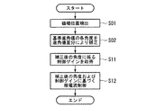
先ず、例えば図4に示すステップS01においては、磁極位置検出器6により回転子4の磁極位置を検出し、この検出値である回転角度θactに対して、磁極位置検出器6の検出誤差を補正する処理を実行し、補正磁極回転角θcを算出する。
次に、ステップS02においては、適宜の基準進角値での各実磁極回転角に進角値差分が加算されてなる磁極回転角θの変化を示す角度置換マップにおいて、補正磁極回転角θcを実磁極回転角として、補正磁極回転角θcを磁極回転角θへと置換する。
次に、ステップS03においては、角度置換マップにより置換された磁極回転角θに基づく相電流制御を実行し、一連の処理を終了する。
The motor control device 1 according to the above-described embodiment has the above-described configuration. Next, referring to the operation of the motor control device 1, in particular, the angle substitution map, the correction magnetic pole rotation angle θc is changed to the magnetic pole rotation angle θ. The replacement process will be described with reference to the accompanying drawings.
First, for example, in step S01 shown in FIG. 4, the magnetic
Next, in step S02, the correction magnetic pole rotation angle θc is set in the angle replacement map showing the change of the magnetic pole rotation angle θ obtained by adding the advance angle difference to each actual magnetic pole rotation angle at an appropriate reference advance angle value. As the actual magnetic pole rotation angle, the correction magnetic pole rotation angle θc is replaced with the magnetic pole rotation angle θ.
Next, in step S03, phase current control based on the magnetic pole rotation angle θ replaced by the angle replacement map is executed, and a series of processes is terminated.
上述したように、本実施形態によるブラシレスDCモータの制御装置10によれば、予め複数の相電流進角値毎のトルク波形のデータに基づいて設定した角度置換マップを参照して、補正磁極回転角θcを磁極回転角θへと置換するだけの単純な処理でトルク脈動の発生を抑制することができ、例えば相電流の波高値を増幅してしまう処理が不要であることから、制御処理が複雑化することを防止することができる。
As described above, according to the brushless DC
なお、上述した実施形態においては、例えば図3に示すように、電気角で360°の範囲に亘る実磁極回転角に対して磁極回転角θの変化を示すデータを角度置換マップとして設定したが、これに限定されず、例えばステータ巻線への励磁切換周期(例えば、3相のモータ3では電気角で60°)に亘る実磁極回転角に対して磁極回転角θの変化を示すデータを角度置換マップとして設定してもよい。
また、上述した実施形態においては、実磁極回転角に対して磁極回転角θの変化を示すデータを角度置換マップとして設定したが、これに限定されず、実磁極回転角に対して磁極回転角θの変化を示すデータを適宜の数式で近似し、この数式に基づき磁極回転角θを算出するように設定してもよい。
In the embodiment described above, for example, as shown in FIG. 3, data indicating a change in the magnetic pole rotation angle θ with respect to the actual magnetic pole rotation angle over a range of 360 ° in electrical angle is set as an angle replacement map. However, the present invention is not limited to this, for example, data indicating a change in the magnetic pole rotation angle θ with respect to the actual magnetic pole rotation angle over the excitation switching period to the stator winding (for example, 60 ° in electrical angle in the three-phase motor 3). It may be set as an angle replacement map.
In the above-described embodiment, the data indicating the change in the magnetic pole rotation angle θ with respect to the actual magnetic pole rotation angle is set as the angle replacement map. However, the present invention is not limited to this. Data indicating a change in θ may be approximated by an appropriate mathematical formula, and the magnetic pole rotation angle θ may be calculated based on this mathematical formula.
なお、上述した実施形態においては、角度置換マップにより置換された磁極回転角θに基づき相電流制御を実行するとしたが、これに限定されず、例えば図5に示すように、さらに、モータ3に対する出力指令に係る各種状態量に応じた適宜の制御ゲインを設定し、角度置換マップにより置換された磁極回転角θを、設定された制御ゲインに基づき補正し、補正後の磁極回転角θにより相電流制御を実行してもよい。
つまり、この変形例では、先ず、図5に示すステップS01において、磁極位置検出器6により回転子4の磁極位置を検出し、この検出値である回転角度θactに対して、磁極位置検出器6の検出誤差を補正する処理を実行し、補正磁極回転角θcを算出する。
次に、ステップS02においては、適宜の基準進角値での各実磁極回転角に進角値差分が加算されてなる磁極回転角θの変化を示す角度置換マップにおいて、補正磁極回転角θcを実磁極回転角として、補正磁極回転角θcを磁極回転角θへと置換する。
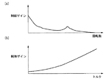
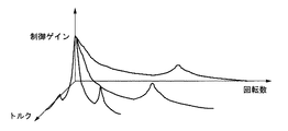
次に、ステップS11においては、モータ3に対する出力指令に係る各種状態量(例えば図6(a),(b)に示すモータ3の回転数やトルクあるいは図7に示すモータ3の回転数およびトルク等)に応じて変化する制御ゲインを取得する。
次に、ステップS12においては、角度置換マップにより置換された磁極回転角θを、取得した制御ゲインに基づき補正し、補正後の磁極回転角θにより相電流制御を実行し、一連の処理を終了する。
例えば図6(a),(b)に示すように、制御ゲインは、モータ3の回転数の増大に伴い減少傾向に変化し、モータ3のトルクの増大に伴い増大傾向に変化するように設定されている。そして、角度置換マップにより置換された磁極回転角θに、モータ3の回転数あるいはトルクに応じた制御ゲインが作用させられ、磁極回転角θがさらに補正される。そして、制御ゲインにより補正された磁極回転角θは電流座標変換器12及び電圧座標変換器16へ出力され、座標変換処理に利用される。
In the above-described embodiment, the phase current control is executed based on the magnetic pole rotation angle θ replaced by the angle replacement map. However, the present invention is not limited to this. For example, as shown in FIG. An appropriate control gain is set according to various state quantities related to the output command, the magnetic pole rotation angle θ replaced by the angle replacement map is corrected based on the set control gain, and the phase is determined by the corrected magnetic pole rotation angle θ. Current control may be performed.
That is, in this modified example, first, in step S01 shown in FIG. 5, the magnetic
Next, in step S02, the correction magnetic pole rotation angle θc is set in the angle replacement map showing the change of the magnetic pole rotation angle θ obtained by adding the advance angle difference to each actual magnetic pole rotation angle at an appropriate reference advance angle value. As the actual magnetic pole rotation angle, the correction magnetic pole rotation angle θc is replaced with the magnetic pole rotation angle θ.
Next, in step S11, various state quantities related to the output command to the motor 3 (for example, the rotation speed and torque of the
Next, in step S12, the magnetic pole rotation angle θ replaced by the angle replacement map is corrected based on the acquired control gain, the phase current control is executed using the corrected magnetic pole rotation angle θ, and the series of processes is completed. To do.
For example, as shown in FIGS. 6A and 6B, the control gain is set so as to decrease as the rotation speed of the
1 モータ制御装置
3 ブラシレスDCモータ
4 回転子(ロータ)
6 磁極位置検出器(磁極位置検出手段)
8 PWMインバータ回路(主回路、通電切換手段)
9 電流指令生成器(電流制御手段)
10 電流指令切換器(電流制御手段)
11u 相電流検出器(電流制御手段)
11v 相電流検出器(電流制御手段)
12 電流座標変換器(電流制御手段)
13,14 減算処理器(電流制御手段)
15 電圧指令生成器(電流制御手段)
16 電圧座標変換器(電流制御手段)
18 位相補正器(角度置換手段)
ステップS11 補正手段
DESCRIPTION OF SYMBOLS 1
6 Magnetic pole position detector (Magnetic pole position detection means)
8 PWM inverter circuit (main circuit, energization switching means)
9 Current command generator (current control means)
10 Current command selector (current control means)
11u phase current detector (current control means)
11v phase current detector (current control means)
12 Current coordinate converter (current control means)
13, 14 Subtraction processor (current control means)
15 Voltage command generator (current control means)
16 Voltage coordinate converter (current control means)
18 Phase corrector (angle replacement means)
Step S11 Correction means
Claims (8)
前記磁極位置検出手段による前記磁極位置角度の検出値に、角度毎に応じた角度補正値を加算して得た値を、新たに前記磁極位置角度として設定する角度置換手段と、
前記角度置換手段により設定された前記磁極位置角度と、前記電動機の出力に対する指令である出力指令とに基づき、前記電動機に供給する前記電流を制御する電流制御手段と
を備えることを特徴とするモータ制御装置。 A main circuit for supplying a current to the electric motor, a magnetic pole position detecting means for detecting a magnetic pole position angle of the rotor, and
Angle replacement means for newly setting a value obtained by adding an angle correction value corresponding to each angle to the detected value of the magnetic pole position angle by the magnetic pole position detection means, as the magnetic pole position angle;
A motor comprising: current control means for controlling the current supplied to the electric motor based on the magnetic pole position angle set by the angle replacing means and an output command which is a command for the output of the electric motor. Control device.
複数のスイッチング素子からなり、d軸電圧およびq軸電圧の2相電圧から変換されてなる3相電圧に応じて前記ステータ巻線への通電を順次転流させることで前記ロータを回転駆動させる通電切換手段を備えることを特徴とする請求項1から請求項7の何れかひとつに記載のモータ制御装置。
The electric motor includes a rotor having a permanent magnet, and a stator having a three-phase stator winding that generates a rotating magnetic field that rotates the rotor.
An energization comprising a plurality of switching elements and rotating the rotor by sequentially commutating energization to the stator winding according to a three-phase voltage converted from a two-phase voltage of a d-axis voltage and a q-axis voltage The motor control apparatus according to claim 1, further comprising a switching unit.
Priority Applications (1)
| Application Number | Priority Date | Filing Date | Title |
|---|---|---|---|
| JP2005074903A JP4642512B2 (en) | 2005-03-16 | 2005-03-16 | Motor control device |
Applications Claiming Priority (1)
| Application Number | Priority Date | Filing Date | Title |
|---|---|---|---|
| JP2005074903A JP4642512B2 (en) | 2005-03-16 | 2005-03-16 | Motor control device |
Publications (2)
| Publication Number | Publication Date |
|---|---|
| JP2006262589A true JP2006262589A (en) | 2006-09-28 |
| JP4642512B2 JP4642512B2 (en) | 2011-03-02 |
Family
ID=37101206
Family Applications (1)
| Application Number | Title | Priority Date | Filing Date |
|---|---|---|---|
| JP2005074903A Expired - Fee Related JP4642512B2 (en) | 2005-03-16 | 2005-03-16 | Motor control device |
Country Status (1)
| Country | Link |
|---|---|
| JP (1) | JP4642512B2 (en) |
Cited By (3)
| Publication number | Priority date | Publication date | Assignee | Title |
|---|---|---|---|---|
| US8204641B2 (en) | 2009-07-31 | 2012-06-19 | Denso Corporation | Traction motor control apparatus for vehicle |
| US8487563B2 (en) | 2009-11-27 | 2013-07-16 | Denso Corporation | Drive motor control apparatus for vehicle, motor control system, method for correcting rotation angle of motor, program for performing the same, rotation detecting apparatus |
| CN112640291A (en) * | 2018-08-31 | 2021-04-09 | 株式会社爱德克斯 | Motor control device |
Citations (2)
| Publication number | Priority date | Publication date | Assignee | Title |
|---|---|---|---|---|
| JPH09298899A (en) * | 1996-04-26 | 1997-11-18 | Fanuc Ltd | Magnetic saturation correction system for ac servo motor |
| JPH11332298A (en) * | 1998-05-18 | 1999-11-30 | Toyota Motor Corp | Apparatus and method for control of motor |
-
2005
- 2005-03-16 JP JP2005074903A patent/JP4642512B2/en not_active Expired - Fee Related
Patent Citations (2)
| Publication number | Priority date | Publication date | Assignee | Title |
|---|---|---|---|---|
| JPH09298899A (en) * | 1996-04-26 | 1997-11-18 | Fanuc Ltd | Magnetic saturation correction system for ac servo motor |
| JPH11332298A (en) * | 1998-05-18 | 1999-11-30 | Toyota Motor Corp | Apparatus and method for control of motor |
Cited By (3)
| Publication number | Priority date | Publication date | Assignee | Title |
|---|---|---|---|---|
| US8204641B2 (en) | 2009-07-31 | 2012-06-19 | Denso Corporation | Traction motor control apparatus for vehicle |
| US8487563B2 (en) | 2009-11-27 | 2013-07-16 | Denso Corporation | Drive motor control apparatus for vehicle, motor control system, method for correcting rotation angle of motor, program for performing the same, rotation detecting apparatus |
| CN112640291A (en) * | 2018-08-31 | 2021-04-09 | 株式会社爱德克斯 | Motor control device |
Also Published As
| Publication number | Publication date |
|---|---|
| JP4642512B2 (en) | 2011-03-02 |
Similar Documents
| Publication | Publication Date | Title |
|---|---|---|
| US8174220B2 (en) | Apparatus for controlling permanent-magnet rotary electric machine | |
| JP3688673B2 (en) | Control device for permanent magnet type rotating electrical machine | |
| JP4754417B2 (en) | Control device for permanent magnet type rotating electrical machine | |
| JP4452735B2 (en) | Boost converter control device and control method | |
| US9112436B2 (en) | System for controlling controlled variable of rotary machine | |
| US9479106B2 (en) | Apparatus for controlling rotary machine | |
| JP2006280141A (en) | Constant detector and control unit of motor for hybrid vehicle | |
| JP2007274779A (en) | Electromotive drive control device, and electromotive drive control method | |
| JP5169797B2 (en) | Control device for permanent magnet type rotating electrical machine | |
| JP4652176B2 (en) | Control device for permanent magnet type rotating electrical machine | |
| JP2006304441A (en) | Synchronous motor control device | |
| JP4642645B2 (en) | Electric motor control device | |
| JP2004254423A (en) | Motor controller | |
| JP4642512B2 (en) | Motor control device | |
| JP2008072858A (en) | Controller of vehicle rotary electric machine | |
| JP2012138982A (en) | Motor controller and electric apparatus | |
| JP5222630B2 (en) | Motor control device | |
| JP7304891B2 (en) | Rotating machine control device and electric vehicle control device | |
| JP5262267B2 (en) | Three-phase AC motor drive device | |
| JP4735287B2 (en) | Synchronous motor control device and control method using the synchronous motor control device | |
| JP7267457B2 (en) | power converter | |
| JP2015073396A (en) | Control apparatus and control method for electric motor | |
| JP5038008B2 (en) | Motor control device | |
| JP5458626B2 (en) | Motor control drive device | |
| JP2018014789A (en) | Electric oil pump and electric oil pump system |
Legal Events
| Date | Code | Title | Description |
|---|---|---|---|
| A621 | Written request for application examination |
Free format text: JAPANESE INTERMEDIATE CODE: A621 Effective date: 20071129 |
|
| A977 | Report on retrieval |
Free format text: JAPANESE INTERMEDIATE CODE: A971007 Effective date: 20100708 |
|
| A131 | Notification of reasons for refusal |
Free format text: JAPANESE INTERMEDIATE CODE: A131 Effective date: 20100713 |
|
| A521 | Written amendment |
Free format text: JAPANESE INTERMEDIATE CODE: A523 Effective date: 20100908 |
|
| TRDD | Decision of grant or rejection written | ||
| A01 | Written decision to grant a patent or to grant a registration (utility model) |
Free format text: JAPANESE INTERMEDIATE CODE: A01 Effective date: 20101124 |
|
| A01 | Written decision to grant a patent or to grant a registration (utility model) |
Free format text: JAPANESE INTERMEDIATE CODE: A01 |
|
| A61 | First payment of annual fees (during grant procedure) |
Free format text: JAPANESE INTERMEDIATE CODE: A61 Effective date: 20101201 |
|
| R150 | Certificate of patent or registration of utility model |
Ref document number: 4642512 Country of ref document: JP Free format text: JAPANESE INTERMEDIATE CODE: R150 Free format text: JAPANESE INTERMEDIATE CODE: R150 |
|
| FPAY | Renewal fee payment (event date is renewal date of database) |
Free format text: PAYMENT UNTIL: 20131210 Year of fee payment: 3 |
|
| LAPS | Cancellation because of no payment of annual fees |