JP2006254532A - Electric power steering device - Google Patents
Electric power steering device Download PDFInfo
- Publication number
- JP2006254532A JP2006254532A JP2005064008A JP2005064008A JP2006254532A JP 2006254532 A JP2006254532 A JP 2006254532A JP 2005064008 A JP2005064008 A JP 2005064008A JP 2005064008 A JP2005064008 A JP 2005064008A JP 2006254532 A JP2006254532 A JP 2006254532A
- Authority
- JP
- Japan
- Prior art keywords
- command value
- phase
- voltage command
- value
- voltage
- Prior art date
- Legal status (The legal status is an assumption and is not a legal conclusion. Google has not performed a legal analysis and makes no representation as to the accuracy of the status listed.)
- Pending
Links
Images


Abstract
Description
本発明は、ブラシレスモータを用いた電動パワーステアリング装置に関し、特に、電源電圧を最大限に利用できるブラシレスモータを用いた電動パワーステアリング装置に関する。 The present invention relates to an electric power steering apparatus using a brushless motor, and more particularly to an electric power steering apparatus using a brushless motor that can make maximum use of a power supply voltage.
自動車などの車両のステアリング装置をモータの回転力で補助力を付与する電動パワーステアリング装置では、モータの駆動力を減速機を介してギア又はベルト等の伝達機構により、ステアリングシャフト或いはラック軸に補助力を付与するようになっている。このような電動パワーステアリング装置の簡単な構成を図1を参照して説明する。操向ハンドル101の軸102は、減速ギア103、ユニバーサルジョイント104a及び104b、ピニオンラック機構105を経て、操向車輪のタイロッド106に結合されている。軸102には,操向ハンドル101の操舵トルクを検出するトルクセンサ107が設けられており、操向ハンドル101の操舵力を補助するモータ108が、減速ギア103を介して軸102に連結されている。
In an electric power steering device that applies an assisting force to a steering device of a vehicle such as an automobile by a rotational force of a motor, the driving force of the motor is assisted to a steering shaft or a rack shaft by a transmission mechanism such as a gear or a belt via a reduction gear. It is designed to give power. A simple configuration of such an electric power steering apparatus will be described with reference to FIG. A
このように構成された電動パワーステアリング装置の制御について、図2を参照して説明する。まず、トルクセンサ107で検出されたトルクTと、図示しない車速センサで検出された車速Vとが、アシストマップ190に入力され、操舵補助指令値が算出される。さらに、補償値演算部194で演算される補償値、例えば、収斂性演算部191や慣性演算部192で算出された収斂性や慣性などの補償値を、加算部195、196、197で前記操舵補助指令値に加算して、トルク指令値Trefが決定される。そして、電流指令値演算部200では、トルク指令値Trefに基いて電流指令値Irefが決定される。
The control of the electric power steering apparatus configured as described above will be described with reference to FIG. First, the torque T detected by the
なお、モータ108として、ブラシレスモータを用いた場合には、トルク指令値Trefの他に、図示しないロータ位置検出器で検出したモータの回転角度θも、電流指令値演算部200に入力され、電流指令値Irefが、トルク指令値Tref及びモータの回転角度θに基いて決定される。
When a brushless motor is used as the
一方、モータ108へ供給されるモータ電流Imは、電流検出器202で検出され、前記電流指令値Irefとともに電流制御手段へ入力される。例えば、この電流制御手段としてフィードバック電流制御を用いた場合に、つまり、電流制御手段は偏差演算部と電流制御部(その一例として、例えば、比例積分項を用いる比例積分制御部)とから構成される場合に、減算器を用いる偏差演算部で、電流指令値Irefとモータ電流Imとの偏差ΔI=Iref−Imが算出され、次に、算出された偏差ΔIは、比例積分制御部に入力され、そして、比例積分制御部から電圧指令値Vrefが出力される。
On the other hand, the motor current Im supplied to the
また、PWM制御部212では、電圧指令値Vrefを入力として、インバータ回路214へのPWM信号を出力することにより、電圧指令値Vrefに基いたPWM信号をインバータ回路214に指示するようになっている。そして、インバータ回路214では、そのPWM信号に基いてモータ108へモータ電流Imを供給する。
Further, the
要するに、上述のように、ブラシレスモータを用いた電動パワーステアリング装置では、電流指令値演算部において、トルク指令値Trefとモータの回転角度θとに基いて電流指令値Irefを算出し、そして、電流指令値Irefとモータ電流Imとの偏差ΔIを解消するようにインバータ回路214を制御することにより、ブラシレスモータをPWM駆動している。
In short, as described above, in the electric power steering apparatus using the brushless motor, the current command value calculation unit calculates the current command value Iref based on the torque command value Tref and the rotation angle θ of the motor, The brushless motor is PWM-driven by controlling the
かかる制御方法において、ブラシレスモータに印加される各相電圧は、一般的に正弦波状であるが、この場合、線間出力電圧(以下、線間印加電圧とも称する)の基本波の振幅が、電源電圧の√3/2以下でしか正常にPWM駆動できないため、電圧利用効率が悪い。 In such a control method, each phase voltage applied to the brushless motor is generally sinusoidal, but in this case, the amplitude of the fundamental wave of the line output voltage (hereinafter also referred to as the line applied voltage) Since the PWM drive can be normally performed only at a voltage of √3 / 2 or less, the voltage use efficiency is poor.
電動パワーステアリング装置では、車両のバッテリによりモータを駆動し、操舵アシスト力を発生する。ところが、車両のバッテリの電圧は一定ではなく、その使用状況により電圧が変化する。しかし、電動パワーステアリング装置では、通常14Vあるバッテリ電圧が9V程度まで電圧低下した場合においても、正常に動作することが要求される。 In the electric power steering apparatus, a motor is driven by a vehicle battery to generate a steering assist force. However, the voltage of the battery of the vehicle is not constant, and the voltage changes depending on the usage situation. However, the electric power steering apparatus is required to operate normally even when the battery voltage, which is normally 14V, drops to about 9V.
このように電源環境が厳しい電動パワーステアリング装置では、電源電圧を最大限に利用することが望ましい。電源電圧の利用効率悪化とは、モータ最大出力の低下を意味し、電動パワーステアリング装置の性能低下をも意味する。 In such an electric power steering apparatus having a severe power supply environment, it is desirable to make maximum use of the power supply voltage. The deterioration of the power supply voltage utilization efficiency means a reduction in the motor maximum output, and also means a reduction in the performance of the electric power steering apparatus.
このような問題を解決するために、例えば、特許文献1に開示された電動パワーステアリング装置が有る。特許文献1の電動パワーステアリング装置では、電圧指令値に3次高調波を重畳して電圧指令値の最大値を下げることにより、電源電圧の効率を向上させるようにしている。
しかし、特許文献1に開示された電動パワーステアリング装置では、電気角に基づいて電圧指令値の3次高調波を算出しているため、電圧指令値が電気角に対してずれている場合、重畳した3次高調波のピークがずれてしまう問題が発生する。
However, since the electric power steering device disclosed in
より詳細に説明すると、電圧指令値は、実電流が電流指令値に追従するように電流制御されて算出された値であるので、高速回転時などの場合に、電圧指令値が電気角に対してずれていることがある。また、逆起電圧値を電圧指令値に加算しているので、これによっても電圧指令値が電気角に対してずれる。そのため、特許文献1のように、電気角に基づいて3次高調波を算出した場合に、重畳した3次高調波のピークがずれてしまう。ずれ量によっては、電圧指令値の最大値を低減することができなくて、つまり、電圧指令値のピークがつぶれないという問題が発生してしまう。
More specifically, the voltage command value is a value calculated by controlling the current so that the actual current follows the current command value. May be off. Further, since the counter electromotive voltage value is added to the voltage command value, the voltage command value also shifts with respect to the electrical angle. For this reason, when the third harmonic is calculated based on the electrical angle as in
上述したように、従来の電動パワーステアリング装置では、ブラシレスモータの各相への印加電圧を正弦波電圧とした場合に、線間出力電圧の基本波の振幅が電源電圧の√3/2以下の範囲でしか正常にPWM駆動できず、よって、電源電圧の利用効率が悪化するといった問題が生じてしまう。また、電動パワーステアリング装置では、バッテリ電圧でモータを駆動するため、電源電圧の利用効率の低下は、電動パワーステアリング装置の性能低下につながり、好ましくない。 As described above, in the conventional electric power steering apparatus, when the applied voltage to each phase of the brushless motor is a sine wave voltage, the amplitude of the fundamental wave of the line output voltage is less than √3 / 2 of the power supply voltage. The PWM drive can be normally performed only within the range, and thus the problem that the use efficiency of the power supply voltage deteriorates arises. Moreover, in the electric power steering apparatus, since the motor is driven by the battery voltage, a decrease in the use efficiency of the power supply voltage leads to a decrease in the performance of the electric power steering apparatus, which is not preferable.
また、特許文献1に開示された電動パワーステアリング装置では、ずれ量によっては、電圧指令値の最大値を低減することができなくて、つまり、電圧指令値のピークがつぶれないという問題がある。
Further, the electric power steering device disclosed in
本発明は、上述のような事情よりなされたものであり、本発明の目的は、線間出力電圧の基本波の振幅が電源電圧以下の範囲で正常にPWM駆動でき、電源電圧を最大限に利用できる電動パワーステアリング装置を提供することにある。 The present invention has been made under the circumstances as described above, and an object of the present invention is to enable normal PWM drive in the range where the fundamental wave amplitude of the line-to-line output voltage is less than or equal to the power supply voltage, and to maximize the power supply voltage. An object is to provide an electric power steering device that can be used.
本発明は、操向ハンドルの操舵トルクを検出するトルクセンサと、3以上の相を有する操舵補助用のブラシレスモータと、前記トルクセンサで検出した前記操舵トルクに基いて算出されたトルク指令値Trefに基いて、d軸電流指令値とq軸電流指令値とを算出する電流指令値算出手段とを具備した電動パワーステアリング装置に関し、本発明の上記目的は、前記電流指令値算出手段で算出されたd軸電流指令値及びq軸電流指令値に基いて、前記ブラシレスモータの各相の相電流指令値を算出する各相電流指令値算出手段と、前記各相電流指令値算出手段で算出された各相の相電流指令値に基いて、各相の電圧指令値を出力する電流制御手段と、前記電流制御手段から出力された各相の電圧指令値を入力とし、前記各相の電圧指令値の最大値を低減する電圧指令値補正により、得られた各相の電圧指令補正値を出力する電圧指令値補正手段と、前記電圧指令値補正手段から出力された各相の電圧指令補正値に基いて、PWM信号を生成するPWM制御手段と、前記PWM制御手段で生成されたPWM信号に基いて、前記ブラシレスモータをPWM駆動するモータ駆動回路とを備えることによって効果的に達成される。 The present invention relates to a torque sensor that detects steering torque of a steering wheel, a brushless motor for steering assistance having three or more phases, and a torque command value Tref calculated based on the steering torque detected by the torque sensor. In accordance with the electric power steering apparatus comprising the current command value calculation means for calculating the d-axis current command value and the q-axis current command value, the above object of the present invention is calculated by the current command value calculation means. Based on the d-axis current command value and the q-axis current command value, each phase current command value calculation means for calculating a phase current command value for each phase of the brushless motor and each phase current command value calculation means are calculated. Based on the phase current command value for each phase, the current control means for outputting the voltage command value for each phase, and the voltage command value for each phase output from the current control means as inputs, the voltage command for each phase Value Based on the voltage command value correction means for outputting the voltage command correction value for each phase obtained by voltage command value correction for reducing the value, and the voltage command correction value for each phase output from the voltage command value correction means. This is achieved effectively by including PWM control means for generating a PWM signal and a motor drive circuit for PWM driving the brushless motor based on the PWM signal generated by the PWM control means.
また、本発明の上記目的は、前記電圧指令値補正手段は、前記各相の電圧指令値から所定の補正電圧値をそれぞれ減算して、前記各相の電圧指令補正値を得るようにすることにより、或いは、前記電圧指令値補正手段では、前記ブラシレスモータの電気角と回転速度に基づいて、前記各相の電圧指令値の基本波の位相を算出し、算出された位相に合わせて得られた3次高調波を前記所定の補正電圧値とすることにより、或いは、前記電圧指令値補正手段では、前記各相の電圧指令値のうち、最大値と最小値を平均した電圧指令値平均値を前記所定の補正電圧値とすることにより、或いは、前記電圧指令値補正手段では、前記各相の電圧指令値から、まず、前記各相の電圧指令値のうち最大値と最小値を平均した電圧指令値平均値をそれぞれ減算し、そして、更に、前記各相の電圧指令値の基本波の位相を算出して得られた3次高調波をそれぞれ減算した結果を前記各相の電圧指令補正値とすることによって一層効果的に達成される。 Further, the object of the present invention is to obtain the voltage command correction value for each phase by subtracting a predetermined correction voltage value from the voltage command value for each phase. Alternatively, the voltage command value correction means calculates the phase of the fundamental wave of the voltage command value of each phase based on the electrical angle and rotation speed of the brushless motor, and obtains it in accordance with the calculated phase. By setting the third harmonic as the predetermined correction voltage value, or in the voltage command value correction means, a voltage command value average value obtained by averaging the maximum value and the minimum value among the voltage command values of each phase. Or the voltage command value correcting means first averages the maximum value and the minimum value of the voltage command values of each phase from the voltage command value of each phase. Decrease voltage command value average value respectively Further, it is more effective by subtracting the third harmonic obtained by calculating the phase of the fundamental wave of the voltage command value of each phase as the voltage command correction value of each phase. To be achieved.
本発明に係る電動パワーステアリング装置によれば、ブラシレスモータの各相の電圧指令値の最大値を低減する電圧指令値補正により、得られた各相の電圧指令補正値に基いて生成されたPWM信号に基いて、ブラシレスモータをPWM駆動しているので、線間出力電圧の基本波の振幅が電源電圧以下の範囲で正常にPWM駆動でき、電源電圧を最大限に利用でき、電源電圧の利用効率を向上させることができ、高性能な電動パワーステアリング装置を提供できるといった優れた効果を奏する。 According to the electric power steering device of the present invention, the PWM generated based on the voltage command correction value of each phase obtained by the voltage command value correction that reduces the maximum value of the voltage command value of each phase of the brushless motor. Since the brushless motor is PWM driven based on the signal, the PWM can be driven normally within the range where the amplitude of the fundamental wave of the line output voltage is below the power supply voltage, the power supply voltage can be maximized, and the power supply voltage can be used. The efficiency can be improved, and an excellent effect that a high-performance electric power steering device can be provided is achieved.
以下に、図面を参照しながら、本発明の実施の形態を詳細に説明する。 Hereinafter, embodiments of the present invention will be described in detail with reference to the drawings.
本発明の電動パワーステアリング装置は、3以上の相を有するブラシレスDCモータ(以下、単に、ブラシレスモータとも称する)を用い、線間出力電圧の基本波の振幅が電源電圧以下の範囲で正常にPWM駆動でき、電源電圧を最大限に利用できるものである。 The electric power steering apparatus of the present invention uses a brushless DC motor having three or more phases (hereinafter also simply referred to as a brushless motor), and performs PWM normally within a range where the amplitude of the fundamental wave of the output voltage between the lines is equal to or lower than the power supply voltage. It can be driven and the power supply voltage can be utilized to the maximum.
なお、以下の実施形態では、操舵補助用のモータとして、3相ブラシレスモータを用いることを前提とする。 In the following embodiments, it is assumed that a three-phase brushless motor is used as a steering assist motor.
本発明の電動パワーステアリング装置の基本的な制御ブロック図を図3に示す。なお、図3に示す本発明の電動パワーステアリング装置において、ベクトル制御相電流指令値算出手段10の入力であるトルク指令値Trefは、図2に示す従来の電動パワーステアリング装置におけるトルク指令値Trefの算出方法を用いて、算出することができるので、本発明では、図3に限らず他の実施例でも、このトルク指令値Trefの算出方法についての説明を省略する。 FIG. 3 shows a basic control block diagram of the electric power steering apparatus of the present invention. In the electric power steering apparatus of the present invention shown in FIG. 3, the torque command value Tref, which is an input of the vector control phase current command value calculation means 10, is the torque command value Tref in the conventional electric power steering apparatus shown in FIG. Since the calculation can be performed using the calculation method, the description of the calculation method of the torque command value Tref is omitted in the present invention not only in FIG. 3 but also in other embodiments.
図3に示されるように、本発明の電動パワーステアリング装置では、電流指令値算出部11と各相電流指令値算出部12で構成されるベクトル制御相電流指令値算出手段10と、電流制御手段20と、電圧指令値補正部30と、PWM制御部212と、インバータ回路214と、ロータ位置検出器40と、3相ブラシレスモータ108と、3相ブラシレスモータ108の各相のモータ相電流Ia,Ib,Icを検出するための電流検出器202−1,202−2,202−3とを備えている。
As shown in FIG. 3, in the electric power steering apparatus of the present invention, a vector control phase current command value calculation unit 10 including a current command value calculation unit 11 and each phase current command value calculation unit 12, and a
ベクトル制御相電流指令値算出手段10において、電流指令値算出部11では、トルクセンサで検出した操舵トルクに基いて算出されたトルク指令値Trefに基いて、d軸電流指令値Idとq軸電流指令値Iqとを算出し、また、各相電流指令値算出部12では、電流指令値算出部11で算出されたd軸電流指令値Id及びq軸電流指令値Iqとロータ位置検出器40で検出したモータの回転角度θとに基いて、3相ブラシレスモータ108の各相の相電流指令値Iaref,Ibref,Icrefを算出するように構成される。
In the vector control phase current command value calculation means 10, the current command value calculation unit 11 uses the d-axis current command value Id and the q-axis current based on the torque command value Tref calculated based on the steering torque detected by the torque sensor. The command value Iq is calculated, and each phase current command value calculation unit 12 calculates the d-axis current command value Id and the q-axis current command value Iq calculated by the current command value calculation unit 11 and the
電流制御手段20は、フィードバック制御方式(FB制御)を用い、ベクトル制御相電流指令値算出手段10から出力された3相ブラシレスモータ108の各相の相電流指令値Iaref,Ibref,Icrefと、電流検出器202−1,202−2,202−3で検出された各相のモータ相電流Ia,Ib,Icとに基いて、各相の電圧指令値Varef,Vbref,Vcrefを出力するように構成される。
The current control means 20 uses a feedback control method (FB control) and outputs phase current command values Iaref, Ibref, Icref for each phase of the three-
ここで、図3に示す本発明の電動パワーステアリング装置において、フィードバック制御方式(FB制御)を用いた電流制御手段20の詳細を示したのは、図4である。図4に示されるように、3相ブラシレスモータ108へ供給されるモータ相電流Ia,Ib,Icは、電流検出器202−1,202−2,202−3で検出され、相電流指令値Iaref,Ibref,Icrefとともに電流制御手段20へ入力される。
Here, FIG. 4 shows the details of the current control means 20 using the feedback control method (FB control) in the electric power steering apparatus of the present invention shown in FIG. As shown in FIG. 4, motor phase currents Ia, Ib, and Ic supplied to the three-
ここで、電流制御手段20は、偏差演算部である減算器21−1,21−2,21−3と、電流制御部としての比例積分項を用いる比例積分制御部(PI制御部)22−1,22−2,22−3とから構成され、減算器21−1,21−2,21−3によって、相電流指令値Iarefとモータ相電流Iaとの偏差ΔIa=Iaref−Ia、相電流指令値Ibrefとモータ相電流Ibとの偏差ΔIb=Ibref−Ib及び相電流指令値Icrefとモータ相電流Icとの偏差ΔIc=Icref−Icが算出される。次に、算出された偏差ΔIa、ΔIb及びΔIcは、PI制御部22−1,22−2,22−3にそれぞれ入力され、そして、PI制御部22−1から電圧指令値Varefが、PI制御部22−2から電圧指令値Vbrefが、PI制御部22−3から電圧指令値Vcrefが、それぞれ出力される。
Here, the
次に、図3及び図4に示すように、電流制御手段20から出力されたブラシレスモータ108の各相の電圧指令値Varef,Vbref及びVcrefは、本発明のポイントである電圧指令値補正手段としての電圧指令値補正部30に入力される。電圧指令値補正部30の具体的な構成は後述する。電圧指令値補正部30では、各相の電圧指令値Varef,Vbref及びVcrefの最大値を低減する電圧指令値補正により、得られた各相の電圧指令補正値V’aref,V’bref及びV’crefをPWM制御部212に出力する。
Next, as shown in FIGS. 3 and 4, the voltage command values Varef, Vbref and Vcref of each phase of the
PWM制御部212では、各相の電圧指令補正値V’aref,V’bref及びV’crefに応じて、ブラシレスモータ108をPWM駆動するためのPWM信号(PWM波形)を生成する。従って、モータ駆動回路として機能するインバータ回路214によって、各相の電圧指令値Varef,Vbref及びVcrefの最大値を低減して得られた各相の電圧指令補正値V’aref,V’bref及びV’crefに基いて生成されたPWM信号に基いて、ブラシレスモータ108をPWM駆動することができる。
The
以上にように構成した本発明の電動パワーステアリング装置では、電圧指令値補正部30により、3相ブラシレスモータ108の各相への印加電圧が補正される。
In the electric power steering apparatus of the present invention configured as described above, the voltage command
次に、本発明のポイントである電圧指令値補正部30の具体的な構成について詳細に説明する。本発明の電圧指令値補正部では、各相の電圧指令値Varef,Vbref及びVcrefから所定の補正電圧値をそれぞれ減算して、各相の電圧指令補正値値V’aref,V’bref及びV’crefを得るようにしている。所定の補正電圧値は、次のような幾つかの方法で求めることができる。
Next, a specific configuration of the voltage command
まず、図5に示されるように、3相ブラシレスモータの電気角と回転速度に基づいて、3相の電圧指令値Varef,Vbref及びVcrefの基本波の位相を算出し、その基本波の3次高調波を所定の補正電圧値(以下、この所定の補正電圧値を3次高調波補正電圧値とも称する)とする。 First, as shown in FIG. 5, based on the electrical angle and rotational speed of the three-phase brushless motor, the phase of the fundamental wave of the three-phase voltage command values Varef, Vbref and Vcref is calculated, and the third order of the fundamental wave is calculated. The harmonic is set to a predetermined correction voltage value (hereinafter, the predetermined correction voltage value is also referred to as a third harmonic correction voltage value).
要するに、ここで、電圧指令値補正部30では、電圧指令値Varef,Vbref及びVcrefに電圧指令値の基本波の3次高調波を重畳させることにより、電圧指令値Varef,Vbref及びVcrefの最大値(ピーク)を下げるようにしている。
In short, the voltage command
電圧指令値Varef,Vbref及びVcrefの最大値を下げるには、電圧指令値Varef,Vbref及びVcrefの位相とその3次高調波の位相とをあわせなければならない。電圧指令値Varef,Vbref及びVcrefの位相は、相電流指令値Iaref,Ibref及びIcrefの位相から、電流制御の応答性の分だけずれる。ずれ量は、モータ回転数によって変わるので、ずれ量とモータ回転数との関係を予め求めておけば、電圧指令値Varef,Vbref及びVcrefの位相を求めることができる。位相を進める方向に補正させるため、以下、このずれ量を進角値とも称する。 In order to reduce the maximum values of the voltage command values Varef, Vbref, and Vcref, the phase of the voltage command values Varef, Vbref, and Vcref and the phase of the third harmonic must be matched. The phases of voltage command values Varef, Vbref, and Vcref are shifted from the phase of phase current command values Iaref, Ibref, and Icref by the amount of current control response. Since the deviation amount varies depending on the motor rotation speed, the phase of the voltage command values Varef, Vbref and Vcref can be obtained if the relationship between the deviation amount and the motor rotation speed is obtained in advance. In order to correct the phase in the advancing direction, hereinafter, this deviation amount is also referred to as an advance value.
図5に示されるように、まず、予め求めておいたずれ量とモータ回転数との関係に基づいて、モータ回転数から、進角値を算出する。そして、モータの電気角を進角補正とする。次に、進角補正された進角値を3倍して、更にsin関数を通過させることにより、電圧指令値の基本波の3次高調波信号を算出することができる。また、電圧指令値の振幅の最大値とゲイン(1/6)を乗じて、電圧指令値の基本波の3次高調波の振幅とする。このようにして、3次高調波補正電圧値が得られる。 As shown in FIG. 5, first, an advance value is calculated from the motor rotational speed based on the relationship between the amount of deviation and the motor rotational speed obtained in advance. Then, the electrical angle of the motor is set as advance angle correction. Next, the third-order harmonic signal of the fundamental wave of the voltage command value can be calculated by multiplying the advance value whose lead angle has been corrected by three times and further passing the sin function. Moreover, the maximum value of the amplitude of the voltage command value and the gain (1/6) are multiplied to obtain the amplitude of the third harmonic of the fundamental wave of the voltage command value. In this way, the third harmonic correction voltage value is obtained.
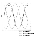
本発明の電圧指令値補正部30では、所定の補正電圧値が3次高調波補正電圧値の場合、図6に示すように3相ブラシレスモータ108への印加電圧が補正される。つまり、図6に示す波形は、補正前後の1相への印加電圧波形、及び所定の補正電圧値(3次高調波補正電圧値)を示している。図6から明らかなように、電圧指令値にその基本波の3次高調波を重畳させることによって、電圧指令値のピークを下げることができた。
In the voltage command
なお、図5において、電圧指令値の基本波の3次高調波の振幅を電圧指令値の振幅の最大値の6分の1にすることにより、各相電圧指令値の最大値(ピーク)を最も効率よく低減することができる。 In FIG. 5, by setting the amplitude of the third harmonic of the fundamental wave of the voltage command value to 1/6 of the maximum value of the voltage command value, the maximum value (peak) of each phase voltage command value is set. It can be reduced most efficiently.
次に、電圧指令値補正部30の他の具体例について説明する。つまり、図7に示されるように、3相の電圧指令値Varef,Vbref及びVcrefのうち、最大値と最小値を平均した電圧指令値平均値を所定の補正電圧値(以下、この所定の補正電圧値を電圧指令値平均値補正電圧値、あるいは、単に平均値補正電圧値とも称する)とする。
Next, another specific example of the voltage command
要するに、ここで、電圧指令値補正部30では、電圧指令値Varef,Vbref及びVcrefの平均値(電圧指令値平均値)を所定の補正電圧値にすることにより、電圧指令値Varef,Vbref及びVcrefの最大値(ピーク)を下げるようにしている。
In short, in the voltage command
電圧指令値Varef,Vbref及びVcrefの最大値を下げるには、電圧指令値Varef,Vbref及びVcrefの位相と電圧指令値平均値の位相とをあわせなければならない。進角値は電流制御の応答性によって変わるので、電流制御の応答性が安定でない場合に、電圧指令値Varef,Vbref及びVcrefの位相と電圧指令値平均値の位相とをあわせるのが困難である。そこで、図5に示す位相を合わせる方法と違って、位相をあわせない方法としては、図7に示す方法である。 In order to reduce the maximum values of the voltage command values Varef, Vbref, and Vcref, the phase of the voltage command values Varef, Vbref, and Vcref must be matched with the phase of the voltage command value average value. Since the advance value changes depending on the current control response, it is difficult to match the phase of the voltage command values Varef, Vbref and Vcref with the phase of the average voltage command value when the current control response is not stable. . Therefore, unlike the method of adjusting the phase shown in FIG. 5, the method of not adjusting the phase is the method shown in FIG.
図7に示されるように、まず、各相電圧指令値の最大値と最小値とを求め、つまり、3相の電圧指令値Varef,Vbref及びVcrefのうち、その最大値と最小値とを求める。次に、求められた最大値と最小値との平均値を求める。求めた平均値を所定の補正電圧値にする。つまり、その平均値を電圧指令値Varef,Vbref及びVcrefからそれぞれ減算することにより、電圧指令値の基本波の位相に合せることなく電圧指令値Varef,Vbref及びVcrefの最大値を低減することができる。 As shown in FIG. 7, first, the maximum value and the minimum value of each phase voltage command value are obtained, that is, the maximum value and the minimum value among the three-phase voltage command values Varef, Vbref, and Vcref are obtained. . Next, an average value of the obtained maximum value and minimum value is obtained. The obtained average value is set to a predetermined correction voltage value. That is, by subtracting the average value from the voltage command values Varef, Vbref, and Vcref, respectively, the maximum values of the voltage command values Varef, Vbref, and Vcref can be reduced without matching the phase of the fundamental wave of the voltage command value. .
本発明の電圧指令値補正部30では、所定の補正電圧値が電圧指令値平均値補正電圧値の場合、図8に示すように3相ブラシレスモータ108への印加電圧が補正される。つまり、図8に示す波形は、補正前後の1相への印加電圧波形、及び所定の補正電圧値(電圧指令値平均値補正電圧値)を示している。図8から明らかなように、電圧指令値からその電圧指令値平均値を減算することによって、電圧指令値のピークを下げることができた。
In the voltage command
更に、本発明の電圧指令値補正部30では、図5に示す電圧指令値補正方法と図7に示す電圧指令値補正方法とを同時に用いることができる。つまり、本発明の電圧指令値補正部30では、各相の電圧指令値Varef,Vbref及びVcrefから、まず、各相の電圧指令値Varef,Vbref及びVcrefのうち最大値と最小値を平均した電圧指令値平均値をそれぞれ減算し、そして、更に、各相の電圧指令値Varef,Vbref及びVcrefの基本波の位相を算出して得られた3次高調波(図5及びその説明を参照)をそれぞれ減算した結果を各相の電圧指令補正値とするようにしても良い。
Furthermore, the voltage command
以上のように、本発明の電動パワーステアリング装置において、3相ブラシレスモータが用いられている場合に、各相への印加電圧は120度ずつ位相がずれており、線間への印加電圧を考えた場合、補正前後で線間への印加電圧波形は、同じ正弦波電圧となる。 As described above, in the electric power steering apparatus of the present invention, when a three-phase brushless motor is used, the applied voltage to each phase is shifted by 120 degrees, and the applied voltage between the lines is considered. In this case, the applied voltage waveform between the lines before and after the correction is the same sine wave voltage.
よって、本発明の電圧指令値補正手段で電圧指令値補正が行われた場合には、電圧指令値補正無しの場合と同一の線間印加電圧を得るのに、必要な各相への印加電圧の振幅が小さくてよいということになり、線間印加電圧の基本波の振幅が電源電圧以下の範囲で正常にPWM駆動でき、電源電圧を最大限に利用できる。 Therefore, when the voltage command value correction is performed by the voltage command value correction means of the present invention, the applied voltage to each phase required to obtain the same line-to-line applied voltage as in the case without voltage command value correction. Thus, the PWM can be normally driven within the range where the amplitude of the fundamental wave of the applied voltage between the lines is equal to or lower than the power supply voltage, and the power supply voltage can be utilized to the maximum.
なお、以上の実施形態では、モータ電流(モータ相電流)として正弦波電流又はモータに印加される各相電圧として正弦波電圧を用いてベクトル制御の電動パワーステアリング装置に、本発明を適用することを説明したが、本発明はそれに限定されること無く、例えば、特許文献2に開示された『矩形波モータのベクトル制御』のような非正弦波(つまり、疑似矩形波)電圧指令値によって制御されるモータを用いた電動パワーステアリング装置にも適用することが可能である。 In the above embodiment, the present invention is applied to a vector-controlled electric power steering apparatus using a sine wave current as a motor current (motor phase current) or a sine wave voltage as each phase voltage applied to the motor. However, the present invention is not limited thereto, and is controlled by a voltage command value of a non-sinusoidal wave (that is, a pseudo rectangular wave) such as “vector control of a rectangular wave motor” disclosed in Patent Document 2, for example. The present invention can also be applied to an electric power steering device using a motor.
ここで、特許文献2でいう『矩形波モータ』とは、電圧指令値波形もモータ電流波形も非正弦波(つまり、疑似矩形波)のモータのことを意味する。 Here, the “rectangular wave motor” referred to in Patent Document 2 means a motor whose voltage command value waveform and motor current waveform are non-sinusoidal waves (that is, pseudo-rectangular waves).
また、特許文献2に開示された『矩形波モータのベクトル制御』に本発明を適用し、更に、本発明の電圧指令値補正部30では、所定の補正電圧値が電圧指令値平均値補正電圧値の場合、図9に示すように3相ブラシレスモータへの印加電圧が補正される。つまり、図9に示す波形は、補正前後の1相への印加電圧波形、及び所定の補正電圧値(電圧指令値平均値補正電圧値)を示している。図9から明らかなように、電圧指令値からその電圧指令値平均値を減算することによって、電圧指令値のピークを下げることができた。
Further, the present invention is applied to “vector control of a rectangular wave motor” disclosed in Patent Document 2, and in the voltage command
図8と図9を比較して分かるように、図8における補正前の電圧指令値は正弦波であるのに対して、図9における補正前の電圧指令値は非正弦波(つまり、疑似矩形波)である。しかし、電圧指令値の基本波の位相に合せる必要のない図7に示す本発明の電圧指令値補正方法を、正弦波の電圧指令値にも、非正弦波(つまり、疑似矩形波)の電圧指令値にも、適用することができる。 As can be seen by comparing FIG. 8 and FIG. 9, the voltage command value before correction in FIG. 8 is a sine wave, whereas the voltage command value before correction in FIG. Wave). However, the voltage command value correction method of the present invention shown in FIG. 7 that does not need to match the phase of the fundamental wave of the voltage command value is applied to a non-sine wave (that is, pseudo-rectangular wave) voltage even for a sine voltage command value. It can also be applied to command values.
次に、電流制御手段20として、フィードフォワード制御(FF制御)と外乱オブザーバとで構成された場合に、本発明を適用した電動パワーステアリング装置の制御ブロック図を図10に示す。 Next, FIG. 10 shows a control block diagram of an electric power steering apparatus to which the present invention is applied when the current control means 20 is configured by feedforward control (FF control) and a disturbance observer.
図10に示されるように、本発明の電動パワーステアリング装置では、電流指令値算出部11と各相電流指令値算出部12で構成されるベクトル制御相電流指令値算出手段10と、電流制御手段20と、電圧指令値補正部30と、PWM制御部212と、インバータ回路214と、図示しないロータ位置検出器40と、3相ブラシレスモータ108と、3相ブラシレスモータ108の各相のモータ相電流Ia,Ib,Icを検出するための電流検出器202−1,202−2,202−3とを備えている。なお、ベクトル制御相電流指令値算出手段10については、図3と同じであるために、その説明を省略する。
As shown in FIG. 10, in the electric power steering apparatus of the present invention, a vector control phase current command value calculation unit 10 including a current command value calculation unit 11 and each phase current command value calculation unit 12, and a
電流制御手段20は、図10に示されるように、フィードフォワード制御(FF制御)を用い、ベクトル制御相電流指令値算出手段10から出力された3相ブラシレスモータ108の各相の相電流指令値Iaref,Ibref,Icrefと、電流検出器202−1,202−2,202−3で検出された各相のモータ相電流Ia,Ib,Icに基いて算出された外乱電圧値Vadis,Vbdis,Vcdisとに基づいて、算出された指令値を電圧指令値補正部30に出力するように構成される。
As shown in FIG. 10, the
ここで、図10における電流制御手段20をより詳細に説明する。電流制御手段20では、電流制御部としてのFF制御部23−1,23−2,23−3と、加算回路としての加算器24−1,24−2,24−3と、外乱オブザーバ演算部25−1,25−2,25−3とから構成される。 Here, the current control means 20 in FIG. 10 will be described in more detail. In the current control means 20, FF control units 23-1, 23-2, 23-3 as current control units, adders 24-1, 24-2, 24-3 as addition circuits, and a disturbance observer calculation unit 25-1, 25-2, 25-3.
FF制御部23−1,23−2,23−3では、ベクトル制御相電流指令値算出手段10から出力された3相ブラシレスモータ108の各相の相電流指令値Iaref,Ibref,Icrefをそれぞれ入力とし、各相の電圧指令値Varef,Vbref,Vcrefを、加算器24−1,24−2,24−3にそれぞれ入力する。
In the FF control units 23-1, 23-2, and 23-3, the phase current command values Iaref, Ibref, and Icref of the respective phases of the three-
一方、外乱オブザーバ演算部25−1,25−2,25−3では、基本的に、各相の電圧指令値Varef,Vbref,Vcrefと、モータ相電流Ia,Ib,Icとの差をとるのであるが、各相の電圧指令値Varef,Vbref,Vcrefに対してLPF回路26−1,26−2,26−3を通過させた値と、出力であるモータ相電流Ia,Ib,Icに対してもLPF回路27−1,27−2,27−3を通過させた値との差である外乱電圧値Vadis,Vbdis,Vcdisを減算回路28−1,28−2,28−3で算出している。ここで、LPF回路を通過させるのは、検出値であるモータ電流Iなどに含まれるノイズなどを除去するためである。 On the other hand, the disturbance observer calculation units 25-1, 25-2, and 25-3 basically take the difference between the voltage command values Varef, Vbref, and Vcref of each phase and the motor phase currents Ia, Ib, and Ic. However, the voltage command values Varef, Vbref, and Vcref of each phase are passed through the LPF circuits 26-1, 26-2, and 26-3, and the motor phase currents Ia, Ib, and Ic that are outputs. However, the disturbance voltage values Vadis, Vbdis, Vcdis, which are the differences from the values passed through the LPF circuits 27-1, 27-2, 27-3, are calculated by the subtracting circuits 28-1, 28-2, 28-3. ing. Here, the reason why the LPF circuit is passed is to remove noise included in the motor current I as a detection value.
外乱オブザーバ演算部25−1,25−2,25−3から出力された外乱電圧値Vadis,Vbdis,Vcdisも、加算器24−1,24−2,24−3にそれぞれ入力される。加算器24−1,24−2,24−3の出力である(Varef+Vadis),(Vbref+Vbdis),(Vcref+Vcdis)は、電圧指令値補正部30にそれぞれ入力される。
Disturbance voltage values Vadis, Vbdis, and Vcdis output from the disturbance observer calculation units 25-1, 25-2, and 25-3 are also input to the adders 24-1, 24-2, and 24-3, respectively. The outputs of the adders 24-1, 24-2, and 24-3 (Varef + Vadis), (Vbref + Vbdis), and (Vcref + Vcdis) are input to the voltage command
電圧指令値補正部30では、(Varef+Vadis),(Vbref+Vbdis),(Vcref+Vcdis)の最大値を低減する電圧指令値補正により、得られた各相の電圧指令補正値V’aref,V’bref及びV’crefをPWM制御部212に出力する。上述した電圧指令値補正部30の具体的な電圧指令値補正方法は、図10に示す電動パワーステアリング装置に適用できることは、言うまでもない。
In the voltage command
ただし、図3及び図4における電圧指令値補正部30の説明において、使用される各相の電圧指令値Varef,Vbref,Vcrefは、図10における電圧指令値補正部30の説明をする際に、それぞれ(Varef+Vadis),(Vbref+Vbdis),(Vcref+Vcdis)に置き換えられる。
However, in the description of the voltage command
PWM制御部212では、各相の電圧指令補正値V’aref,V’bref及びV’crefに応じて、ブラシレスモータ108をPWM駆動するためのPWM信号(PWM波形)を生成する。従って、モータ駆動回路として機能するインバータ回路214によって、(Varef+Vadis),(Vbref+Vbdis),(Vcref+Vcdis)の最大値を低減して得られた各相の電圧指令補正値V’aref,V’bref及びV’crefに基いて生成されたPWM信号に基いて、ブラシレスモータ108をPWM駆動することができる。
The
以上にように構成した本発明の電動パワーステアリング装置では、電圧指令値補正部30により、3相ブラシレスモータ108の各相への印加電圧が補正される。
In the electric power steering apparatus of the present invention configured as described above, the voltage command
なお、以上の実施形態では、ブラシレスモータの中でも多用される3相ブラシレスモータを例として、本発明の電動パワーステアリング装置について説明するが、本発明はこれに限定されるものではなく、他の相数を有するブラシレスモータ、例えば、5相ブラシレスモータについても、同様に本発明を適用できることは言うまでもない。 In the above embodiment, the electric power steering apparatus of the present invention will be described by taking a three-phase brushless motor frequently used among brushless motors as an example. However, the present invention is not limited to this, and other phases are described. It goes without saying that the present invention can be similarly applied to a brushless motor having a number, for example, a five-phase brushless motor.
10 ベクトル制御相電流算出手段
11 電流指令値算出部
12 各相電流指令値算出部
20 電流制御手段
21−1,21−2,21−3 減算器
22−1,22−2,22−3 PI制御部
23−1,23−2,23−3 FF制御部
24−1,24−2,24−3 加算器
25−1,25−2,25−3 外乱オブザーバ演算部(外乱オブザーバ回路)
26−1,26−2,26−3 LPF回路
27−1,27−2,27−3 LPF回路
28−1,28−2,28−3 減算回路
30 電圧指令値補正部
40 ロータ位置検出器
108 ブラシレスモータ
212 PWM制御部
214 インバータ回路
202−1,202−2,202−3 電流検出器
DESCRIPTION OF SYMBOLS 10 Vector control phase current calculation means 11 Current command value calculation part 12 Each phase current command
26-1, 26-2, 26-3 LPF circuits 27-1, 27-2, 27-3 LPF circuits 28-1, 28-2, 28-3
Claims (5)
3以上の相を有する操舵補助用のブラシレスモータと、
前記トルクセンサで検出した前記操舵トルクに基いて算出されたトルク指令値Trefに基いて、d軸電流指令値とq軸電流指令値とを算出する電流指令値算出手段とを具備した電動パワーステアリング装置において、
前記電流指令値算出手段で算出されたd軸電流指令値及びq軸電流指令値に基いて、前記ブラシレスモータの各相の相電流指令値を算出する各相電流指令値算出手段と、
前記各相電流指令値算出手段で算出された各相の相電流指令値に基いて、各相の電圧指令値を出力する電流制御手段と、
前記電流制御手段から出力された各相の電圧指令値を入力とし、前記各相の電圧指令値の最大値を低減する電圧指令値補正により、得られた各相の電圧指令補正値を出力する電圧指令値補正手段と、
前記電圧指令値補正手段から出力された各相の電圧指令補正値に基いて、PWM信号を生成するPWM制御手段と、
前記PWM制御手段で生成されたPWM信号に基いて、前記ブラシレスモータをPWM駆動するモータ駆動回路と、
を備えることを特徴とする電動パワーステアリング装置。 A torque sensor for detecting the steering torque of the steering wheel;
A brushless motor for steering assistance having three or more phases;
Electric power steering comprising current command value calculation means for calculating a d-axis current command value and a q-axis current command value based on a torque command value Tref calculated based on the steering torque detected by the torque sensor In the device
Each phase current command value calculating means for calculating a phase current command value for each phase of the brushless motor based on the d-axis current command value and the q-axis current command value calculated by the current command value calculating means;
Current control means for outputting a voltage command value for each phase based on the phase current command value for each phase calculated by each phase current command value calculation means;
Using the voltage command value of each phase output from the current control means as an input, output the voltage command correction value of each phase obtained by voltage command value correction that reduces the maximum value of the voltage command value of each phase Voltage command value correction means;
PWM control means for generating a PWM signal based on the voltage command correction value of each phase output from the voltage command value correction means;
A motor drive circuit for PWM driving the brushless motor based on the PWM signal generated by the PWM control means;
An electric power steering apparatus comprising:
Priority Applications (1)
| Application Number | Priority Date | Filing Date | Title |
|---|---|---|---|
| JP2005064008A JP2006254532A (en) | 2005-03-08 | 2005-03-08 | Electric power steering device |
Applications Claiming Priority (1)
| Application Number | Priority Date | Filing Date | Title |
|---|---|---|---|
| JP2005064008A JP2006254532A (en) | 2005-03-08 | 2005-03-08 | Electric power steering device |
Publications (2)
| Publication Number | Publication Date |
|---|---|
| JP2006254532A true JP2006254532A (en) | 2006-09-21 |
| JP2006254532A5 JP2006254532A5 (en) | 2008-04-17 |
Family
ID=37094427
Family Applications (1)
| Application Number | Title | Priority Date | Filing Date |
|---|---|---|---|
| JP2005064008A Pending JP2006254532A (en) | 2005-03-08 | 2005-03-08 | Electric power steering device |
Country Status (1)
| Country | Link |
|---|---|
| JP (1) | JP2006254532A (en) |
Cited By (4)
| Publication number | Priority date | Publication date | Assignee | Title |
|---|---|---|---|---|
| JP2010119201A (en) * | 2008-11-12 | 2010-05-27 | Toyota Motor Corp | Controller for ac motor |
| JP2019146479A (en) * | 2016-07-20 | 2019-08-29 | 日本精工株式会社 | Electric power steering device |
| EP3588767A4 (en) * | 2017-10-26 | 2020-11-18 | NSK Ltd. | Motor control device, motor control method, and electric power steering device |
| WO2021106373A1 (en) * | 2019-11-26 | 2021-06-03 | 日本精工株式会社 | Motor control device, electric actuator product, and electric power steering device |
Citations (4)
| Publication number | Priority date | Publication date | Assignee | Title |
|---|---|---|---|---|
| JP2001145381A (en) * | 1999-11-12 | 2001-05-25 | Toyota Motor Corp | Controller of motor |
| JP2003079181A (en) * | 2001-09-04 | 2003-03-14 | Mitsubishi Electric Corp | Electric power steering control equipment and control method |
| JP2003304697A (en) * | 2002-04-09 | 2003-10-24 | Koyo Seiko Co Ltd | Motor-driven power steering device |
| JP2004201487A (en) * | 2002-11-28 | 2004-07-15 | Nsk Ltd | Motor and its drive controlling apparatus |
-
2005
- 2005-03-08 JP JP2005064008A patent/JP2006254532A/en active Pending
Patent Citations (4)
| Publication number | Priority date | Publication date | Assignee | Title |
|---|---|---|---|---|
| JP2001145381A (en) * | 1999-11-12 | 2001-05-25 | Toyota Motor Corp | Controller of motor |
| JP2003079181A (en) * | 2001-09-04 | 2003-03-14 | Mitsubishi Electric Corp | Electric power steering control equipment and control method |
| JP2003304697A (en) * | 2002-04-09 | 2003-10-24 | Koyo Seiko Co Ltd | Motor-driven power steering device |
| JP2004201487A (en) * | 2002-11-28 | 2004-07-15 | Nsk Ltd | Motor and its drive controlling apparatus |
Cited By (8)
| Publication number | Priority date | Publication date | Assignee | Title |
|---|---|---|---|---|
| JP2010119201A (en) * | 2008-11-12 | 2010-05-27 | Toyota Motor Corp | Controller for ac motor |
| JP2019146479A (en) * | 2016-07-20 | 2019-08-29 | 日本精工株式会社 | Electric power steering device |
| EP3588767A4 (en) * | 2017-10-26 | 2020-11-18 | NSK Ltd. | Motor control device, motor control method, and electric power steering device |
| US11001295B2 (en) | 2017-10-26 | 2021-05-11 | Nsk Ltd. | Motor control device, motor control method, and electric power steering device |
| WO2021106373A1 (en) * | 2019-11-26 | 2021-06-03 | 日本精工株式会社 | Motor control device, electric actuator product, and electric power steering device |
| JPWO2021106373A1 (en) * | 2019-11-26 | 2021-12-02 | 日本精工株式会社 | Motor control devices, electric actuator products and electric power steering devices |
| JP7107430B2 (en) | 2019-11-26 | 2022-07-27 | 日本精工株式会社 | Motor control devices, electric actuator products and electric power steering devices |
| US11873039B2 (en) | 2019-11-26 | 2024-01-16 | Nsk Ltd. | Motor control device, electric actuator product, and electric power steering device |
Similar Documents
| Publication | Publication Date | Title |
|---|---|---|
| JP4912874B2 (en) | Control device for electric power steering device | |
| US9136785B2 (en) | Motor control system to compensate for torque ripple | |
| US8150580B2 (en) | Motor controller and electric power steering system | |
| JP5168448B2 (en) | Motor control device and electric power steering device | |
| US8710775B2 (en) | Electric power steering apparatus | |
| EP3300244B1 (en) | Motor control device and electric power steering device equipped with same | |
| WO2018016356A1 (en) | Electric power steering device | |
| US20110221382A1 (en) | Motor control method and apparatus and electric power steering system | |
| JP3433701B2 (en) | Electric power steering device for vehicles | |
| US20140253009A1 (en) | Control apparatus for ac rotating machine and electrically-assisted power steering apparatus provided with the control apparatus | |
| JP2019013135A (en) | Electric power steering device | |
| JP2019097385A (en) | Electric power steering device | |
| JP4650110B2 (en) | Electric motor control device | |
| JP2006254532A (en) | Electric power steering device | |
| JP5397664B2 (en) | Motor control device | |
| JP2007325409A (en) | Motor controller | |
| JP2007116862A (en) | Motor drive control device and motor-driven power steering device on which it is mounted | |
| JP2008154308A (en) | Controller of motor-driven power steering system | |
| JP5028813B2 (en) | Electric power steering apparatus and control apparatus therefor | |
| JP6648592B2 (en) | Motor control device and electric power steering device equipped with the same | |
| JP5880874B2 (en) | Vehicle steering control device | |
| JP2017127066A (en) | Motor controller and electrically-driven power steering device | |
| JP2005199780A (en) | Control device of electric power steering device | |
| JP5743133B2 (en) | Electric power steering device | |
| JP6638471B2 (en) | Motor control device and electric power steering device equipped with the same |
Legal Events
| Date | Code | Title | Description |
|---|---|---|---|
| A521 | Written amendment |
Free format text: JAPANESE INTERMEDIATE CODE: A523 Effective date: 20080229 |
|
| A621 | Written request for application examination |
Free format text: JAPANESE INTERMEDIATE CODE: A621 Effective date: 20080229 |
|
| A977 | Report on retrieval |
Free format text: JAPANESE INTERMEDIATE CODE: A971007 Effective date: 20101025 |
|
| A131 | Notification of reasons for refusal |
Free format text: JAPANESE INTERMEDIATE CODE: A131 Effective date: 20101102 |
|
| A521 | Written amendment |
Free format text: JAPANESE INTERMEDIATE CODE: A523 Effective date: 20101216 |
|
| A02 | Decision of refusal |
Free format text: JAPANESE INTERMEDIATE CODE: A02 Effective date: 20110125 |