JP2006248202A - Liquid storage - Google Patents
Liquid storage Download PDFInfo
- Publication number
- JP2006248202A JP2006248202A JP2005072049A JP2005072049A JP2006248202A JP 2006248202 A JP2006248202 A JP 2006248202A JP 2005072049 A JP2005072049 A JP 2005072049A JP 2005072049 A JP2005072049 A JP 2005072049A JP 2006248202 A JP2006248202 A JP 2006248202A
- Authority
- JP
- Japan
- Prior art keywords
- liquid
- sealing film
- storage chamber
- hole
- ink
- Prior art date
- Legal status (The legal status is an assumption and is not a legal conclusion. Google has not performed a legal analysis and makes no representation as to the accuracy of the status listed.)
- Pending
Links
Images


Abstract
Description
本発明は、例えばインクジェットプリンタに装着されるインクカートリッジとして好適な大気開放タイプの液体収容体に関する。 The present invention relates to an air release type liquid container suitable as an ink cartridge mounted on, for example, an ink jet printer.
インクジェットプリンタに装着されるインクカートリッジ(液体収容体)として、プリンタに装着される容器本体内に、インクを収容するインク収容室(液体収容室)と、インク収容室に連通しプリンタ側の印刷ヘッド(液体噴射部)にインクを供給可能なインク供給孔(液体供給孔)と、インク収容室内のインクの消費に伴って外部から大気をインク収容部内に導入する大気開放孔と、使用前の商品出荷作業等で加わる振動等で大気開放孔からインクが漏れることを防止するために大気開放孔を封止する開放孔封止フィルムと、を備えた構成のものが各種提案されている。 As an ink cartridge (liquid container) to be mounted on an inkjet printer, an ink storage chamber (liquid storage chamber) for storing ink in a container body mounted on the printer, and a print head on the printer side communicating with the ink storage chamber Ink supply holes (liquid supply holes) that can supply ink to the (liquid ejecting section), an air opening hole that introduces air into the ink storage section as the ink in the ink storage chamber is consumed, and a product before use In order to prevent ink from leaking from the air opening holes due to vibrations applied during shipping operations and the like, various types of structures including an open hole sealing film for sealing the air opening holes have been proposed.
従来のこの種のインクカートリッジの開放孔封止フィルムは、ユーザが使用時に手指で引き剥がすことで、大気開放孔の封止を解除するように、商品に注意書きの添付等を行っているものがあった。しかし、ユーザが開放孔封止フィルムを剥がし忘れると、インクの正常な供給ができずに印字不良等を招く原因となった。
そこで、ユーザへの負担を軽減すると同時に、開放孔封止フィルムの剥がし忘れによる不都合の発生を防止するために、カートリッジ上の開放孔封止フィルムの装着位置を見直し、インクカートリッジをプリンタのキャリッジに装着すれば、キャリッジ側に設けられた封止解除突起により自動的に開放孔封止フィルムが突き破られる構成のインクカートリッジが提案されている(例えば、特許文献1参照)。
The conventional open hole sealing film of this type of ink cartridge is a product that is attached with a cautionary note, etc., so that the user releases the air open hole seal by peeling it with fingers during use. was there. However, if the user forgets to peel off the open hole sealing film, the ink cannot be supplied normally, which causes a printing defect and the like.
Therefore, in order to reduce the burden on the user and prevent the occurrence of inconvenience due to forgetting to peel off the open hole sealing film, the mounting position of the open hole sealing film on the cartridge is reviewed, and the ink cartridge is mounted on the carriage of the printer. An ink cartridge has been proposed in which an open hole sealing film is automatically pierced by a sealing release protrusion provided on the carriage side when mounted (see, for example, Patent Document 1).
また、インクカートリッジには、インク収容室を外部に連通させるインク注入孔を容器本体に備えていて、インクの充填後に、インク注入孔を注入孔封止フィルムの貼付によって封止した構成のものもある。 The ink cartridge may have an ink injection hole for communicating the ink storage chamber with the outside of the container body, and the ink injection hole may be sealed by applying an injection hole sealing film after filling the ink. is there.
キャリッジへの装着時にキャリッジ側に設けられた封止解除突起により開放孔封止フィルムが突き破られる構成のインクカートリッジは、通常、封止フィルムの外面全域が露出しており、ユーザが誤って不用意に手指で剥がしてしまってインク漏れを招く虞があった。
また、開放孔封止フィルムの外面全域が露出しているため、商品の搬出作業等の際の落下等で、開放孔封止フィルムの貼付部位に他の器物等が強く衝突した時に、開放孔封止フィルムが破れて、インク漏れ事故を招く虞があった。
Ink cartridges configured such that the open-hole sealing film is pierced by the sealing release protrusion provided on the carriage side when mounted on the carriage, usually, the entire outer surface of the sealing film is exposed, and the user accidentally inadvertently removes it. There was a risk of ink leakage due to peeling off with fingers.
In addition, since the entire outer surface of the open-hole sealing film is exposed, when other items or the like strongly collide with the part to which the open-hole sealing film is applied due to dropping or the like at the time of carrying out the product, etc. There was a possibility that the sealing film was torn and an ink leakage accident was caused.
また、インク注入孔を注入孔封止フィルムの貼付によって封止した構成のインクカートリッジでは、インク注入孔を封止している注入孔封止フィルムは、使用時に剥がす必要が無い(というより、剥がしてはいけない)が、大気開放孔を封止している開放孔封止フィルムと同様または類似しているフィルムを使用しているために、ユーザが誤って剥がしてしまって、インク漏れ事故を招く虞があった。 In addition, in an ink cartridge having a configuration in which the ink injection hole is sealed by sticking the injection hole sealing film, the injection hole sealing film sealing the ink injection hole does not need to be peeled off during use (rather than being peeled off). However, since the film is the same as or similar to the open hole sealing film that seals the open air hole, the user may accidentally peel it off, resulting in an ink leakage accident. There was a fear.
そこで、本発明の目的は、封止フィルムが誤操作で剥がされたり、落下等の衝突で破れて液漏れが発生することがなく、取り扱い性に優れた液体収容体を提供することにある。 Accordingly, an object of the present invention is to provide a liquid container excellent in handleability, in which a sealing film is not peeled off by an erroneous operation or is not torn due to a collision such as dropping to cause liquid leakage.
上記課題を解決することのできる本発明に係る液体収容体は、機器に装着される容器本体内に、液体を貯留する密閉された液体収容室と、前記液体収容室に連通し機器側の液体噴射部に液体を供給可能な液体供給孔と、前記液体収容室を大気に連通させて外部の空気を前記液体収容室内に導入する大気開放孔と、前記大気開放孔を封止すると共に機器への装着時に機器側に設けられた封止解除突起により突き破られて前記大気開放孔の封止を解除する開放孔封止フィルムとを備える液体収容体であって、前記封止解除突起による前記開放孔封止フィルムの封止解除動作を妨げないように前記開放孔封止フィルムの外面を部分的に覆う開放孔カバーが、前記容器本体に装着されていることを特徴としている。 The liquid container according to the present invention that can solve the above-described problems includes a sealed liquid storage chamber that stores liquid in a container main body mounted on the device, and a liquid on the device side that communicates with the liquid storage chamber. A liquid supply hole capable of supplying a liquid to the ejection unit, an air release hole for communicating the liquid storage chamber to the atmosphere and introducing external air into the liquid storage chamber, and sealing the air release hole and to the device An open hole sealing film that is pierced by a seal release protrusion provided on the device side when mounted, and releases the seal of the atmosphere open hole, and the liquid container includes the seal release protrusion An open hole cover that partially covers the outer surface of the open hole sealing film so as not to hinder the sealing release operation of the open hole sealing film is mounted on the container body.
このような構成の液体収容体によれば、大気開放孔を封止する開放孔封止フィルムは、その上が開放孔カバーにより覆われていて、開放孔カバーが、開放孔封止フィルムの手指による剥離操作の抑止と、落下時等に他の器物が開放孔封止フィルムに衝突することの防止を行う。
そのため、開放孔封止フィルムが誤操作で剥がされたり、落下等の衝突で破れて液漏れが発生することがなく、優れた取り扱い性を得ることができる。
According to the liquid container having such a configuration, the open hole sealing film for sealing the air open hole is covered with the open hole cover, and the open hole cover is the finger of the open hole seal film. Inhibition of the peeling operation due to, and prevention of other objects from colliding with the open hole sealing film when dropped or the like.
Therefore, the open hole sealing film is not peeled off by an erroneous operation, or is not torn due to a collision such as dropping, and liquid leakage does not occur, and excellent handleability can be obtained.
また、本発明に係る液体収容体において、前記開放孔封止フィルムの前記封止解除突起により突き破られる部位の周囲に位置する前記開放孔カバーの開口縁部には、前記容器本体を機器に装着する際に機器側の封止解除突起を前記開放孔封止フィルムに向けて誘導するテーパ面が形成されていることが好ましい。 Further, in the liquid container according to the present invention, the container body may be attached to an opening edge portion of the open hole cover located around a portion of the open hole sealing film that is torn through by the sealing release protrusion. It is preferable that a taper surface that guides the device-side seal release protrusion toward the open hole sealing film when mounting is formed.
このような構成の液体収容体によれば、液体収容体を機器に装着する際に、挿入する液体収容体の姿勢の傾き等で機器側の封止解除突起の当たる位置が多少ずれたとしても、テーパ面が封止解除突起を開放孔封止フィルムに向けて誘導するため、封止解除突起が開放孔カバーとの干渉で破損することを回避して、封止解除突起に確実に開放孔封止フィルムを突き破らせることができる。したがって、機器への装着性が向上する。 According to the liquid container having such a configuration, when the liquid container is attached to the device, even if the position where the seal release protrusion on the device side hits slightly shifts due to the inclination of the posture of the liquid container to be inserted, etc. Since the taper surface guides the sealing release protrusion toward the opening hole sealing film, the sealing release protrusion is prevented from being damaged due to interference with the opening hole cover, and the sealing release protrusion is securely opened to the opening hole. The sealing film can be broken through. Therefore, the mounting property to the device is improved.
また、本発明に係る液体収容体において、前記開放孔カバーは、前記容器本体の側面に装着される側面カバーと一体に形成されていることが好ましい。 In the liquid container according to the present invention, it is preferable that the open hole cover is formed integrally with a side cover attached to a side surface of the container body.
このような構成の液体収容体によれば、新規な構成として追加された開放孔カバーが、構成部品の増加を招かず、組立工程や部品の増加によるコストアップを抑止することができる。 According to the liquid container having such a configuration, the open hole cover added as a new configuration does not increase the number of components, and can suppress an increase in cost due to an assembly process or an increase in components.
また、上記課題を解決することのできる本発明に係る液体収容体は、機器に装着される容器本体内に、液体を貯留する密閉された液体収容室と、前記液体収容室に連通し機器側の液体噴射部に液体を供給可能な液体供給孔と、前記液体収容室を大気に連通させて外部の空気を前記液体収容室内に導入する大気開放孔と、前記液体収容室内に液体を充填可能に前記液体収容室を外部に連通させた液体注入孔と、前記液体収容室への液体充填後に前記液体注入孔を封止する注入孔封止フィルムとを備える液体収容体であって、前記注入孔封止フィルムの外面を覆う注入孔カバーが、前記容器本体に装着されていることを特徴としている。 In addition, the liquid container according to the present invention that can solve the above-described problems includes a sealed liquid storage chamber that stores liquid in a container main body mounted on the device, and the device side that communicates with the liquid storage chamber. A liquid supply hole capable of supplying liquid to the liquid ejecting section, an air opening hole for communicating the liquid storage chamber to the atmosphere and introducing external air into the liquid storage chamber, and filling the liquid in the liquid storage chamber A liquid container comprising: a liquid injection hole that communicates the liquid storage chamber to the outside; and an injection hole sealing film that seals the liquid injection hole after filling the liquid storage chamber. An injection hole cover that covers the outer surface of the hole sealing film is mounted on the container body.
このような構成の液体収容体によれば、液体注入孔を封止する注入孔封止フィルムは、その上が注入孔カバーにより覆われていて、注入孔カバーが、注入孔封止フィルムの手指による剥離操作の抑止と、落下時等に他の器物が注入孔封止フィルムに衝突することの防止を行う。
そのため、注入孔封止フィルムが誤操作で剥がされたり、落下等の衝突で破れて液漏れが発生することがなく、優れた取り扱い性を得ることができる。
According to the liquid container having such a configuration, the injection hole sealing film for sealing the liquid injection hole is covered with the injection hole cover, and the injection hole cover is a finger of the injection hole sealing film. Inhibition of the peeling operation by, and prevention of collision of other containers with the injection hole sealing film during dropping or the like.
For this reason, the injection hole sealing film is not peeled off by an erroneous operation, or it is not broken by a collision such as dropping, and liquid leakage does not occur, and excellent handleability can be obtained.
また、本発明に係る液体収容体において、前記注入孔カバーは、前記容器本体の側面に装着される側面カバーと一体に形成されていることが好ましい。 In the liquid container according to the present invention, it is preferable that the injection hole cover is formed integrally with a side cover attached to a side surface of the container body.
このような構成の液体収容体によれば、新規な構成として追加された注入孔カバーが、構成部品の増加を招かず、組立工程や部品の増加によるコストアップを抑止することができる。 According to the liquid container having such a configuration, the injection hole cover added as a new configuration does not increase the number of components, and can suppress an increase in cost due to an assembly process or an increase in components.
本発明に係る液体収容体によれば、封止フィルム(開放孔封止フィルム、注入孔封止フィルム)の上がカバー(開放孔カバー、注入孔カバー)で覆われているため、手指による封止フィルムの剥離が困難になると同時に、落下時等にも封止フィルムが他の器物に衝突することを防止できるため、封止フィルムが誤操作で剥がされたり、落下等の衝突で破れて液漏れが発生することがなく、取り扱い性に優れた液体収容体を提供することができる。 According to the liquid container according to the present invention, the top of the sealing film (open hole sealing film, injection hole sealing film) is covered with the cover (open hole cover, injection hole cover). It becomes difficult to peel off the stop film, and at the same time, it can prevent the sealing film from colliding with other objects even when it is dropped. Therefore, a liquid container excellent in handleability can be provided.
以下、本発明に係る液体収容体の実施の形態の例について、図面を参照しつつ詳細に説明する。
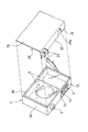
図1から図3は本発明に係る液体収容体の一実施の形態を模式的に示したものであって、図1は本発明に係る液体収容体の一実施の形態の斜め下方から見た斜視図、図2は図1に示した液体収容体のフィルムカバーを取り外した状態の分解斜視図、図3は図1のIII−III線に沿う断面図である。
Hereinafter, an example of an embodiment of a liquid container according to the present invention will be described in detail with reference to the drawings.
1 to 3 schematically show an embodiment of a liquid container according to the present invention, and FIG. 1 is viewed from obliquely below an embodiment of the liquid container according to the present invention. 2 is an exploded perspective view of the liquid container shown in FIG. 1 with the film cover removed, and FIG. 3 is a cross-sectional view taken along line III-III in FIG.
本実施の形態の液体収容体は、インクジェット式プリンタにおいて、液体噴射部である印刷ヘッドが搭載されたキャリッジ上のカートリッジ装着部に装着されるインクカートリッジ1である。 The liquid container according to the present embodiment is an ink cartridge 1 that is mounted on a cartridge mounting portion on a carriage on which a print head that is a liquid ejecting portion is mounted in an ink jet printer.
図1及び図2に示すように、インクカートリッジ1は、機器(プリンタのカートリッジ装着部)に装着される容器本体3内に、インクを貯留する密封構造のインク収容室(液体収容室)5が形成されており、容器本体3の下面には、インク収容室5に連通し、機器側の印刷ヘッドにインクを供給可能なインク供給孔(液体供給孔)7と、インク収容室5を大気に連通させインク収容室5内のインクの消費に伴って外部の空気をインク収容室5内に導入する大気開放孔9と、インク収容室5内にインクを充填可能にインク収容室5を外部に連通させたインク注入孔(液体注入孔)11と、が設けられている。すなわち、インクカートリッジ1は、大気開放タイプのインクカートリッジである。
As shown in FIGS. 1 and 2, the ink cartridge 1 has an ink storage chamber (liquid storage chamber) 5 having a sealed structure for storing ink in a container
容器本体3は、インクの流路となる溝やインク収容室5となる凹部をプロピレン(PP)等の合成樹脂により一体成形した主ケース部材3aを有し、その凹部の開口面(容器本体3の側面)に収容室フィルム3bを気密に融着することで、必要となるインク流路や密封構造のインク収容室5を形成させたものである。収容室フィルム3bは、主ケース部材3aに熱溶着可能な材料から構成された樹脂製フィルムであり、この外側は、保護のために側面カバー25で覆われる。側面カバー25は、溶着、又はねじ止め、または係止突起等による係合等により、容器本体3の主ケース部材3aに固定される。
The
インク供給孔7は、容器本体3の下面に配置され、インクカートリッジ1が装着されるキャリッジに形成されたインク供給針が挿入されて、インク収容室5に収容されたインクをインクジェット式プリンタの印刷ヘッドへ供給する。
The
また、容器本体3の下面には、大気開放孔9及びインク注入孔11が配置されており、大気開放孔9の開口部分には大気開放孔9を封止する開放孔封止フィルム13が貼着され、インク注入孔11の開口部分にはインク収容室5へのインク充填後にインク注入孔11を封止する注入孔封止フィルム15が貼着されている。これらの開放孔封止フィルム13、注入孔封止フィルム15は、収容室フィルム3bと同様に、主ケース部材3aに熱溶着可能な材料から構成された樹脂製フィルムである。
開放孔封止フィルム13は、機器への装着時に機器側に設けられた針状の封止解除突起により破られ、それにより大気開放孔9の封止が解除される。
An air opening
The open
また、本実施の形態のインクカートリッジ1では、キャリッジ側の封止解除突起による開放孔封止フィルム13の封止解除動作を妨げないように開放孔封止フィルム13の外面を部分的に覆う開放孔カバー21と、注入孔封止フィルム15の外面を覆う注入孔カバー22と、先端がインク供給孔7の先端面よりも外方に突出するように高さが設定されてインク供給孔7の外側に配置される供給孔ガイドリブ23とが設けられており、これらの開放孔カバー21、注入孔カバー22、供給孔ガイドリブ23は、側面カバー25と一体に形成されて、その全体がフィルムカバー26として構成されている。
なお、供給孔ガイドリブ23は、容器本体3を機器に装着する際のガイドとして機能する。
Further, in the ink cartridge 1 of the present embodiment, the opening that partially covers the outer surface of the opening
The supply hole guide rib 23 functions as a guide when the
注入孔カバー22は、注入孔封止フィルム15の外面の略全域を覆っている。一方、開放孔カバー21は、キャリッジ側の封止解除突起の挿通を許容する切り欠き21aを有していて、大気開放孔9を中心とする所定半径の円形領域を除く開放孔封止フィルム13の周縁部を覆うようにしている。
The
図3に示すように、開放孔封止フィルム13の封止解除突起により突き破られる部位の周囲に位置する切り欠き21aの開口縁部には、容器本体3を機器に装着する際に、機器側の封止解除突起を開放孔封止フィルム13へ向けて誘導するテーパ面21bが設けられている。
As shown in FIG. 3, when the
以上説明したインクカートリッジ1では、大気開放孔9を封止する開放孔封止フィルム13は、その外面が部分的に開放孔カバー21により覆われている。そのため、開放孔カバー21が、開放孔封止フィルム13の手指による剥離操作の抑止と、落下時等に他の器物が開放孔封止フィルム13に衝突することの防止を行う。したがって、開放孔封止フィルム13が誤操作で剥がされたり、落下等の衝突で破れてインク漏れが発生することがなく、優れた取り扱い性を得ることができる。
In the ink cartridge 1 described above, the outer surface of the open
また、上記インクカートリッジ1では、インクカートリッジ1をキャリッジ上のカートリッジ装着部に装着する際に、挿入するインクカートリッジ1の姿勢の傾き等でキャリッジ側の封止解除突起の当たる位置が多少ずれたとしても、開放孔カバー21の切り欠き21aの開口縁部に形成されたテーパ面21bが封止解除突起を開放孔封止フィルム13上に誘導する。そのため、封止解除突起が開放孔カバー21との干渉で破損することを回避して、封止解除突起に確実に開放孔封止フィルム13を突き破らせることができる。
Further, in the ink cartridge 1, when the ink cartridge 1 is mounted on the cartridge mounting portion on the carriage, the position where the carriage-side seal release protrusion hits is slightly shifted due to the inclination of the posture of the ink cartridge 1 to be inserted. In addition, the tapered
また、上記インクカートリッジ1では、開放孔カバー21は容器本体3の側面に固定される側面カバー25と一体に形成されているため、新規構成として追加された開放孔カバー21が、構成部品の増加を招かず、組立工程や部品の増加によるコストアップを抑止することができる。
Further, in the ink cartridge 1, since the
また、本実施の形態のインクカートリッジ1では、インク注入孔11を封止する注入孔封止フィルム15は、その外面が注入孔カバー22により覆われていて、注入孔カバー22が、注入孔封止フィルム15の手指による剥離操作の抑止と、落下時等に他の器物が注入孔封止フィルム15に衝突することの防止を行う。そのため、注入孔封止フィルム15が誤操作で剥がされたり、落下等の衝突で破れて液漏れが発生することがなく、優れた取り扱い性を得ることができる。
Further, in the ink cartridge 1 of the present embodiment, the injection
また、上記インクカートリッジ1では、注入孔カバー22は容器本体3の側面に固定される側面カバー25と一体に形成されているため、新規構成として追加された注入孔カバー22が、構成部品の増加を招かず、組立工程や部品の増加によるコストアップを抑止することができる。
Further, in the ink cartridge 1, since the
また、本実施の形態のインクカートリッジ1では、大気開放孔9とインク注入孔11とが主ケース部材3aの同一側面(下面)内で隣接して配置されていて、開放孔封止フィルム13と注入孔封止フィルム15の貼着位置が隣接している。そのため、開放孔カバー21と注入孔カバー22とが一体化した部品で提供でき、部品点数の増加防止に貢献している。また、開放孔封止フィルム13と注入孔封止フィルム15とが一体化して1枚の封止フィルムとなっていても良い。
Further, in the ink cartridge 1 of the present embodiment, the
なお、本発明に係る液体収容体の用途は、上記実施の形態に示したインクカートリッジに限らない。例えば、本発明の液体収容体は、液体噴射装置の液体噴射ヘッドに液体を供給するのに適したものである。ここで言う液体噴射装置としては、例えば、インクジェット式記録装置の液体噴射ヘッド(印刷ヘッド)、液晶ディスプレイのカラーフィルタを製造するカラーフィルタ製造装置の色剤噴射ヘッド、有機ELディスプレイ、FED(面発光ディスプレイ)等の電極を形成する電極材(導電ペースト)噴射ヘッド、さらにはバイオチップを製造するバイオチップ製造装置の生体有機物噴射ヘッド及び精密ピペットしての試料噴射ヘッドなどが該当する。 The use of the liquid container according to the present invention is not limited to the ink cartridge shown in the above embodiment. For example, the liquid container according to the present invention is suitable for supplying a liquid to a liquid ejecting head of a liquid ejecting apparatus. Examples of the liquid ejecting apparatus include a liquid ejecting head (printing head) of an ink jet recording apparatus, a colorant ejecting head of a color filter manufacturing apparatus for manufacturing a color filter of a liquid crystal display, an organic EL display, and an FED (surface emitting). Electrode material (conductive paste) ejecting heads for forming electrodes such as displays), bio-organic matter ejecting heads for biochip manufacturing apparatuses for producing biochips, and sample ejecting heads using precision pipettes.
1 インクカートリッジ(液体収容体)
3 容器本体
3a 主ケース部材
3b 収容室フィルム
5 インク収容室(液体収容室)
7 インク供給孔(液体供給孔)
9 大気開放孔
11 インク注入孔(液体注入孔)
13 開放孔封止フィルム
15 注入孔封止フィルム
21 開放孔カバー
21a 切り欠き
21b テーパ面
22 注入孔カバー
23 供給孔ガイドリブ
25 側面カバー
26 フィルムカバー
1 Ink cartridge (liquid container)
3
7 Ink supply hole (liquid supply hole)
9 Air opening hole 11 Ink injection hole (liquid injection hole)
DESCRIPTION OF
Claims (5)
前記封止解除突起による前記開放孔封止フィルムの封止解除動作を妨げないように前記開放孔封止フィルムの外面を部分的に覆う開放孔カバーが、前記容器本体に装着されていることを特徴とする液体収容体。 A sealed liquid storage chamber for storing a liquid in a container body mounted on the device, a liquid supply hole communicating with the liquid storage chamber and capable of supplying a liquid to a liquid ejecting unit on the device side, and the liquid storage chamber Are opened to the atmosphere by introducing external air into the liquid storage chamber, and the atmosphere release hole is sealed and is pierced by a sealing release protrusion provided on the device side when mounted on the device. A liquid container including an open hole sealing film for releasing the sealing of the air open hole,
An open hole cover that partially covers the outer surface of the open hole sealing film is attached to the container body so as not to hinder the seal release operation of the open hole sealing film by the seal release protrusion. Characteristic liquid container.
前記開放孔封止フィルムの前記封止解除突起により突き破られる部位の周囲に位置する前記開放孔カバーの開口縁部には、前記容器本体を機器に装着する際に機器側の封止解除突起を前記開放孔封止フィルムに向けて誘導するテーパ面が形成されていることを特徴とする液体収容体。 The liquid container according to claim 1,
On the opening edge of the open hole cover located around the part to be pierced by the seal release protrusion of the open hole sealing film, when the container body is attached to the device, the device side seal release protrusion The liquid container is characterized in that a tapered surface for guiding the liquid toward the open-hole sealing film is formed.
前記開放孔カバーは、前記容器本体の側面に装着される側面カバーと一体に形成されていることを特徴とする液体収容体。 The liquid container according to claim 1 or 2,
The open hole cover is formed integrally with a side cover attached to a side surface of the container main body.
前記注入孔封止フィルムの外面を覆う注入孔カバーが、前記容器本体に装着されていることを特徴とする液体収容体。 A sealed liquid storage chamber for storing a liquid in a container body mounted on the device, a liquid supply hole communicating with the liquid storage chamber and capable of supplying a liquid to a liquid ejecting unit on the device side, and the liquid storage chamber An atmosphere opening hole for introducing external air into the liquid storage chamber by communicating with the atmosphere, a liquid injection hole for connecting the liquid storage chamber to the outside so that the liquid can be filled in the liquid storage chamber, and the liquid storage A liquid container comprising an injection hole sealing film for sealing the liquid injection hole after filling the chamber with liquid,
An injection hole cover that covers an outer surface of the injection hole sealing film is attached to the container body.
前記注入孔カバーは、前記容器本体の側面に装着される側面カバーと一体に形成されていることを特徴とする液体収容体。 The liquid container according to claim 4,
The liquid container, wherein the injection hole cover is formed integrally with a side cover attached to a side surface of the container body.
Priority Applications (1)
| Application Number | Priority Date | Filing Date | Title |
|---|---|---|---|
| JP2005072049A JP2006248202A (en) | 2005-03-14 | 2005-03-14 | Liquid storage |
Applications Claiming Priority (1)
| Application Number | Priority Date | Filing Date | Title |
|---|---|---|---|
| JP2005072049A JP2006248202A (en) | 2005-03-14 | 2005-03-14 | Liquid storage |
Publications (1)
| Publication Number | Publication Date |
|---|---|
| JP2006248202A true JP2006248202A (en) | 2006-09-21 |
Family
ID=37089169
Family Applications (1)
| Application Number | Title | Priority Date | Filing Date |
|---|---|---|---|
| JP2005072049A Pending JP2006248202A (en) | 2005-03-14 | 2005-03-14 | Liquid storage |
Country Status (1)
| Country | Link |
|---|---|
| JP (1) | JP2006248202A (en) |
Cited By (1)
| Publication number | Priority date | Publication date | Assignee | Title |
|---|---|---|---|---|
| US8182075B2 (en) | 2008-07-15 | 2012-05-22 | Seiko Epson Corporation | Liquid delivery system and manufacturing method thereof |
-
2005
- 2005-03-14 JP JP2005072049A patent/JP2006248202A/en active Pending
Cited By (1)
| Publication number | Priority date | Publication date | Assignee | Title |
|---|---|---|---|---|
| US8182075B2 (en) | 2008-07-15 | 2012-05-22 | Seiko Epson Corporation | Liquid delivery system and manufacturing method thereof |
Similar Documents
| Publication | Publication Date | Title |
|---|---|---|
| CN107379771B (en) | Liquid consuming apparatus | |
| US7934818B2 (en) | Ink cartridges having an air intake valve which is opened in response to the removal of a protection member from a case of the ink cartridge | |
| US8678572B2 (en) | Liquid storage container mounted on liquid ejecting apparatus | |
| US20080316283A1 (en) | Installing fluid container in fluid ejection device | |
| JP2008221803A (en) | Container for containing liquid | |
| JP2010105239A (en) | Liquid container | |
| JP3111039B2 (en) | Inkjet printer head cartridge | |
| JP2008307871A (en) | Refill ink cartridge, and its protecting member | |
| JP2010240907A (en) | Liquid storage container | |
| JP4415629B2 (en) | ink cartridge | |
| JP6098291B2 (en) | Liquid cartridge | |
| TWM445496U (en) | Container lid, liquid receiving container and liquid jetting system | |
| JP5533560B2 (en) | Liquid consumption device | |
| JP2006248202A (en) | Liquid storage | |
| JP4952655B2 (en) | Fluid ejecting apparatus and manufacturing method thereof | |
| JP2008207429A (en) | Fluid holding bag | |
| JP2007283517A (en) | Liquid holding container | |
| JP2016087848A (en) | Liquid consuming system | |
| JP6794620B2 (en) | Bottle | |
| JP2005288777A (en) | Ink cartridge | |
| JP3821498B2 (en) | Inkjet recording unit and ink cartridge | |
| JP2019051605A (en) | Ink supply container and regeneration method for ink supply container | |
| JP2009023336A (en) | Fluid jetting device and its manufacturing method | |
| JP6233062B2 (en) | Liquid supply unit | |
| JP2014097577A (en) | Cap and liquid storage container |