JP2006203296A - Interpolation processing method, interpolation processing program, and imaging apparatus - Google Patents
Interpolation processing method, interpolation processing program, and imaging apparatus Download PDFInfo
- Publication number
- JP2006203296A JP2006203296A JP2005010032A JP2005010032A JP2006203296A JP 2006203296 A JP2006203296 A JP 2006203296A JP 2005010032 A JP2005010032 A JP 2005010032A JP 2005010032 A JP2005010032 A JP 2005010032A JP 2006203296 A JP2006203296 A JP 2006203296A
- Authority
- JP
- Japan
- Prior art keywords
- interpolation
- data
- image data
- coordinate system
- matrix
- Prior art date
- Legal status (The legal status is an assumption and is not a legal conclusion. Google has not performed a legal analysis and makes no representation as to the accuracy of the status listed.)
- Abandoned
Links
- 238000003384 imaging method Methods 0.000 title claims abstract description 48
- 238000003672 processing method Methods 0.000 title claims abstract description 25
- 238000012545 processing Methods 0.000 claims abstract description 48
- 238000006243 chemical reaction Methods 0.000 claims abstract description 34
- 238000009826 distribution Methods 0.000 claims description 53
- 238000000034 method Methods 0.000 claims description 52
- 230000008569 process Effects 0.000 claims description 17
- 238000003860 storage Methods 0.000 claims description 8
- 239000011159 matrix material Substances 0.000 description 172
- 239000013598 vector Substances 0.000 description 81
- 230000009466 transformation Effects 0.000 description 39
- 238000013507 mapping Methods 0.000 description 21
- 238000004364 calculation method Methods 0.000 description 11
- 238000010586 diagram Methods 0.000 description 11
- 238000000354 decomposition reaction Methods 0.000 description 9
- 230000001629 suppression Effects 0.000 description 9
- 230000005540 biological transmission Effects 0.000 description 8
- 238000005070 sampling Methods 0.000 description 8
- 230000000694 effects Effects 0.000 description 7
- 230000003287 optical effect Effects 0.000 description 7
- 230000006835 compression Effects 0.000 description 5
- 238000007906 compression Methods 0.000 description 5
- 230000014509 gene expression Effects 0.000 description 4
- 238000010187 selection method Methods 0.000 description 4
- 230000015572 biosynthetic process Effects 0.000 description 3
- 230000006870 function Effects 0.000 description 3
- 238000003786 synthesis reaction Methods 0.000 description 3
- 230000004075 alteration Effects 0.000 description 2
- 239000003086 colorant Substances 0.000 description 2
- 238000009795 derivation Methods 0.000 description 2
- 239000000284 extract Substances 0.000 description 2
- 238000012546 transfer Methods 0.000 description 2
- 230000008901 benefit Effects 0.000 description 1
- 238000007405 data analysis Methods 0.000 description 1
- 238000013500 data storage Methods 0.000 description 1
- 230000007423 decrease Effects 0.000 description 1
- 238000009792 diffusion process Methods 0.000 description 1
- 230000006872 improvement Effects 0.000 description 1
- 230000010354 integration Effects 0.000 description 1
- 238000004519 manufacturing process Methods 0.000 description 1
- 239000000203 mixture Substances 0.000 description 1
- 230000002093 peripheral effect Effects 0.000 description 1
- 230000035945 sensitivity Effects 0.000 description 1
- 238000000844 transformation Methods 0.000 description 1
- 238000013519 translation Methods 0.000 description 1
Images


Classifications
-
- G—PHYSICS
- G06—COMPUTING; CALCULATING OR COUNTING
- G06T—IMAGE DATA PROCESSING OR GENERATION, IN GENERAL
- G06T3/00—Geometric image transformation in the plane of the image
- G06T3/40—Scaling the whole image or part thereof
- G06T3/4015—Demosaicing, e.g. colour filter array [CFA], Bayer pattern
-
- G06T5/70—
-
- G—PHYSICS
- G06—COMPUTING; CALCULATING OR COUNTING
- G06T—IMAGE DATA PROCESSING OR GENERATION, IN GENERAL
- G06T2200/00—Indexing scheme for image data processing or generation, in general
- G06T2200/12—Indexing scheme for image data processing or generation, in general involving antialiasing
Abstract
Description
本発明は、撮像装置から得られる画像のノイズを抑制するための補間処理に関する。 The present invention relates to an interpolation process for suppressing noise in an image obtained from an imaging apparatus.
従来、デジタルカメラ等の撮像素子(CCDセンサ、CMOSセンサ等のイメージセンサ)を有する撮像装置では、撮影レンズ系により結像した像をイメージセンサでサンプリングすることで偽色やモアレ縞等のエリアジングノイズが発生する。 2. Description of the Related Art Conventionally, in an image pickup apparatus having an image pickup element (an image sensor such as a CCD sensor or a CMOS sensor) such as a digital camera, aliasing such as false colors and moire fringes is performed by sampling an image formed by a photographing lens system with an image sensor. Noise is generated.
一般に通常のノイズは、統計的な性質を考慮することである程度抑制できるが、エリアジングノイズは、被写体に依存して画像の大域的に発生することが多く、通常のノイズ対策を適用することは難しい。 In general, normal noise can be suppressed to some extent by taking statistical properties into account, but aliasing noise often occurs globally in the image depending on the subject. difficult.
このエリアジングノイズを抑制する方法の一つとして、画素間に存在すべき画素値を補間処理で推定し、サンプリング前の画像を復元する方法が挙げられる。この方法では、エリアジングノイズの抑制量が補間処理に影響されるため、補間処理の選択が重要となる。 As one method for suppressing the aliasing noise, there is a method of estimating a pixel value that should exist between pixels by interpolation processing and restoring an image before sampling. In this method, since the amount of suppression of aliasing noise is affected by the interpolation processing, selection of the interpolation processing is important.
従来から撮像装置(撮像系)で用いられる補間処理方法は、例えば、非特許文献1、2に記載の方法が知られている。撮像系で用いられるこれらの補間処理は、色フィルタ配列により各色毎にサンプリングされた画像から全色を有する完全な取得画像を復元するために用いられる。その他に、コンボリューション演算を基本としたものには、nearest neighbor法、bilinear法、cubic convolution法等が知られている。
Conventionally, as an interpolation processing method used in an imaging apparatus (imaging system), for example, methods described in
また、事前に取得された被写体情報を用いた補間処理方法としては、局所領域におけるR色とG色及びB色とG色の強度比が一定であると仮定することで色強度値を推定する方法や、被写体形状をエッジ部分等に分割してから色を推定する方法が提案されている。 Further, as an interpolation processing method using subject information acquired in advance, the color intensity value is estimated by assuming that the intensity ratios of R color and G color and B color and G color in the local region are constant. There have been proposed a method and a method of estimating a color after dividing a subject shape into edge portions or the like.
さらには、一般逆行列のようにより高度な画像復元技術を応用して高い精度での画像復元を行う補間処理方法も提案されている。特許文献1には、原画像から観察画像への写像を行列表記した感度関数を用いて画像を復元する補間処理方法が提案されている。
上記従来のように、イメージセンサでサンプリング前の像を復元することでエリアジングノイズを抑制することは可能であるが、このエリアジングノイズを抑制するためには、高いレベルでの補間精度を必要とする。しかし、コンボリューション演算に基づいたnearest neighbor法や被写体の色情報、エッジ情報を用いた方法等は、補間対象画素のごく近傍の画素値のみを用いて補間処理を行っているため、補間精度が低く、エリアジングノイズの抑制効果が低下してしまう。 Although it is possible to suppress aliasing noise by restoring the pre-sampling image with an image sensor as in the conventional case above, a high level of interpolation accuracy is required to suppress this aliasing noise. And However, the nearest neighbor method based on the convolution operation, the method using the color information of the subject, the edge information, etc. perform interpolation processing using only pixel values in the immediate vicinity of the interpolation target pixel, so the interpolation accuracy is high. The effect of suppressing aliasing noise is lowered.
また、上記特許文献1の補間復元方法のように、原画像から観察画像への写像のみを考慮しても、エリアジングノイズが被写体に依存して発生しているため、制御できない。
Moreover, even if only the mapping from the original image to the observation image is taken into consideration as in the interpolation restoration method of
そこで、本発明の例示的な目的は、エリアジングノイズを好適に抑制可能な補間処理方法、補間処理プログラム及び撮像装置を提供することにある。 Accordingly, an exemplary object of the present invention is to provide an interpolation processing method, an interpolation processing program, and an imaging apparatus that can suitably suppress aliasing noise.
本発明の1つの観点としての補間処理方法(プログラム)は、被写体像を光電変換して得られた画像データに対し、補間データを用いて補間処理を行う補間処理方法であって、被写体情報を推定する第1のステップと、被写体情報に基づいて第1の入力画像データを生成する第2のステップと、第1の入力画像データから前記画像データへの第1の変換データを生成する第3のステップと、第1の入力画像データから補間処理後の補間画像データへの第2の変換データを生成する第4のステップと、第1及び第2の変換データを用いて補間データを生成する第5のステップとを有することを特徴とする。 An interpolation processing method (program) according to one aspect of the present invention is an interpolation processing method for performing interpolation processing using interpolation data on image data obtained by photoelectrically converting a subject image. A first step of estimating, a second step of generating first input image data based on subject information, and a third step of generating first conversion data from the first input image data to the image data. The fourth step of generating the second conversion data from the first input image data to the interpolated image data after the interpolation process, and generating the interpolation data using the first and second conversion data And a fifth step.
本発明によれば、被写体情報に基づいて生成された第1の入力画像データに応じて補間データを生成しているので、エリアジングノイズの被写体への依存性を考慮したノイズ抑制が可能となる。 According to the present invention, since the interpolation data is generated according to the first input image data generated based on the subject information, it is possible to suppress the noise in consideration of the dependence of the aliasing noise on the subject. .
したがって、従来の補間処理では困難であったエリアジングノイズ抑制を好適に制御することが可能となり、良好な画像を復元することができる。 Therefore, it is possible to suitably control aliasing noise suppression that has been difficult in the conventional interpolation process, and a good image can be restored.
以下に本発明の実施例について説明する。 Examples of the present invention will be described below.
まず、実施例での説明に先立ち、本実施例で使用するベクトル、ベクトル空間及び座標系について説明する。本実施例で用いるベクトルは、位置座標を用いて表現したものではなく、物体の輝度値や周波数強度値に次元を与えたもので、例えば、撮像装置で取得した画像は、各画素値を成分としたベクトルxとして以下のように表現できる。 First, prior to the description in the embodiment, vectors, vector spaces, and coordinate systems used in the present embodiment will be described. The vectors used in the present embodiment are not expressed using position coordinates, but are obtained by giving dimensions to the luminance value and frequency intensity value of an object. For example, an image acquired by an imaging apparatus has each pixel value as a component. The vector x can be expressed as follows.
![]()
![]()
そして、本実施例では、このような多次元ベクトル空間を扱い、該多次元ベクトル空間では、座標変換によってデータの表現形態を変えることができる。例えば、数式1に示すベクトルxに対して次式のような座標変換を行うことで画像の周波数分布x´を求めることができる。
In this embodiment, such a multidimensional vector space is handled, and in the multidimensional vector space, the data representation form can be changed by coordinate conversion. For example, the frequency distribution x ′ of the image can be obtained by performing coordinate transformation such as the following equation on the vector x shown in
![]()
![]()
また、座標系は相対的に決まるため、基準となる座標系(単位ベクトルを基底ベクトルとする座標系)を定義する必要があるので、数式1のように画素毎に次元を与えた座標系を画素座標系と称して基準座標とする。 Since the coordinate system is relatively determined, it is necessary to define a reference coordinate system (a coordinate system having a unit vector as a base vector). This is referred to as a pixel coordinate system and is used as a reference coordinate.
図1は本発明の実施例1に係る補間処理方法(補間処理プログラム)を説明するためのフローチャート図である。本実施例における補間処理は、デジタルカメラ、デジタルビデオカメラ等の撮像装置の撮像光学系(レンズ、ミラー、回折格子等を任意に含んでいて構わない)を介して、撮像装置のイメージセンサ等の受光素子(CCDやCMOS等の光電変換素子)で取得した出力画像データを、撮像装置内の演算回路や外部の演算装置等に入力して(S101)、画素座標系のベクトルとして表現するとともに、補間行列(補間データ)Hを生成する(S102)。そして、生成された補間行列Hと出力画像データとを積算し(S103)、補間処理後の補間画像データを得る(S104)。 FIG. 1 is a flowchart for explaining an interpolation processing method (interpolation processing program) according to the first embodiment of the present invention. The interpolation processing in the present embodiment is performed by an image sensor of the imaging device or the like via an imaging optical system of an imaging device such as a digital camera or a digital video camera (which may optionally include a lens, a mirror, a diffraction grating, or the like). Output image data acquired by a light receiving element (photoelectric conversion element such as CCD or CMOS) is input to an arithmetic circuit in an imaging device or an external arithmetic device (S101) and expressed as a vector in a pixel coordinate system, An interpolation matrix (interpolation data) H is generated (S102). Then, the generated interpolation matrix H and output image data are integrated (S103) to obtain interpolated image data after interpolation processing (S104).
ここで、本実施例の補間処理方法における補間行列Hの生成手順を説明する。まず、図1、図2に示すように、物体座標系3を撮像光学系等を介して撮像する(すなわち、変換行列So(変換データSo)を用いて変換する)ことにより得られる出力座標系(出力画像データ)1、目標座標系(補間画像データ)2、仮想入力座標系(第1の入力画像データ)4を設定する。そして、仮想入力座標系4から出力座標系1への写像である変換行列(第1の変換データ)Sと該仮想入力座標系から目標座標系2への写像である変換行列(第2の変換データ)Siを求め(S1022)、変換行列Sの一般逆行列S‐gを算出する(S1023)。この変換行列S、Siを用いて補間行列H=SiS-g を生成する(S1024)。
Here, a procedure for generating the interpolation matrix H in the interpolation processing method of the present embodiment will be described. First, as shown in FIGS. 1 and 2, an output obtained by imaging the
このため、補間処理された補間画像x´は、撮像系の出力画像をxとして以下のように与えられる。 For this reason, the interpolation image x ′ subjected to the interpolation processing is given as follows with the output image of the imaging system as x.
![]()
![]()
図2は本実施例で用いるベクトル空間、座標系、写像の関係を示す図であり、出力座標系1は、撮像系の出力画像ベクトルの座標系、目標座標系2はエリアジングノイズが制御された理想的な画像ベクトル(補間処理後の画像ベクトル)の座標系である。これらの座標系が属するベクトル空間は、撮像系の出力画像を構成する画素数Nより大きい次元N´を有するように設定している。このN´は、被写体の離散化モデルである原画像の画素数に相当しており、出力座標系1と目標座標系2は、N´次元ベクトル空間の部分空間として構成されることになる。
FIG. 2 is a diagram showing the relationship between the vector space, coordinate system, and mapping used in this embodiment. The
そして、本実施例では出力座標系1と目標座標系2としては通常、画素座標系を用いるが、原理的にはユーザーが目的に応じて任意に選択できる。また、エリアジングノイズを説明する場合には周波数座標系を用いており、計算対象である補間行列Hは図2に示すように出力座標系1から目標座標系2への変換行列となる。
In this embodiment, a pixel coordinate system is normally used as the
なお、出力座標系1と目標座標系2が構成する各々の部分空間は異なるため、変換基準を設けなければ補間行列Hが無数に存在することになってしまうので、物体座標系3、つまり原画像(被写体)を表現する画素座標系を設けている。
In addition, since each partial space which the
仮想入力座標系4は、基底ベクトルが正規化されておらず、ノルムが小さい基底ベクトルが存在することを特徴とした座標系である。なお、仮想入力座標系と称しているのは、物体座標系3の基底ベクトルとは異なる基底ベクトルを有しており、ベクトル値が原画像そのものを表さないことを明確に表現するためである。
The virtual input coordinate system 4 is a coordinate system characterized in that a basis vector is not normalized and a basis vector having a small norm exists. The virtual input coordinate system has a basis vector different from the basis vector of the
そして、本実施例ではこのように設定された各座標系を用いて図2に示すように、補間行列Hを出力座標系1→仮想入力座標系4→目標座標系2の経路に沿って生成する。
In the present embodiment, the interpolation matrix H is generated along the path of the
次に、エリアジングノイズと座標変換行列の関係について説明する。エリアジングノイズは広義解釈すると周波数成分だけに限った問題ではないが、ここでは一般的に数式4に示す周波数成分の伝播を用いて説明する。 Next, the relationship between aliasing noise and a coordinate transformation matrix will be described. Aliasing noise is not a problem limited to only frequency components when interpreted in a broad sense, but here, it will be generally described using the propagation of frequency components shown in Equation 4.
![]()
![]()
![]()
![]()
サンプリング行列Psは図3(a)に示すような対角行列で、対角成分が1である次元の画素をサンプリングしている。デフォーカス行列Pdは光学系やイメージセンサの画素開口での電荷拡散によるデフォーカスを表わす行列で、図3(b)に示すように対角成分の近傍の成分に値を有する行列である。デフォーカス量やサンプル点数の情報は既知であるため、Spは容易に求めることができ、数式4の関係式は、以下の数式6のように基底関数を変換して得られる。Fは周波数基底行列である。 The sampling matrix P s is a diagonal matrix as shown in FIG. 3A, and samples pixels of a dimension whose diagonal component is 1. The defocus matrix P d is a matrix representing defocus due to charge diffusion at the pixel aperture of the optical system or image sensor, and is a matrix having a value in the vicinity of the diagonal component as shown in FIG. For information of the defocus amount and the number of samples is known, S p can be easily obtained, the relational expression of Equation 4 is obtained by converting the basis functions as in the following Equation 6. F is a frequency basis matrix.
![]()
![]()
次に、理想的な行列Sνの成分の絶対値の分布を図4(a)に示す。この行列Sνは入出力の周波数成分が1対1に対応し、MTFに相当する重み付けがされるような対角行列であることが望ましい。 Next, the distribution of the absolute values of the components of the ideal matrix S ν is shown in FIG. This matrix S ν is preferably a diagonal matrix in which input and output frequency components correspond to each other on a one-to-one basis and are weighted corresponding to the MTF.
しかし、サンプリング行列により行列Sνの成分は図4(b)に示すように非対角成分にも高いピーク値を有するので、結果として、出力画像xν´の周波数成分に対応しない入力周波数成分が混入することになり、混入した成分がエリアジングノイズとなる。エリアジングノイズの一種であるモアレ縞は、特定の低周波成分に相当する縞模様が画像中に現れるものであるが、これは混入した成分により周波数強度値が強められた結果として理解できる。 However, due to the sampling matrix, the component of the matrix S ν has a high peak value in the non-diagonal component as shown in FIG. 4B, and as a result, the input frequency component that does not correspond to the frequency component of the output image x ν ′. Will be mixed, and the mixed component becomes aliasing noise. Moire fringes, which are a type of aliasing noise, appear in the image as a striped pattern corresponding to a specific low-frequency component, which can be understood as a result of the frequency intensity value being strengthened by the mixed component.
次に、一般逆行列とエリアジングノイズとの関係について説明する。一般逆行列に関しては、W.Menke,Geophysical Data Analysis: Discrete Inverse Theory,Academic Press(1989:邦訳版)に記載されている。本実施例ではエリアジングノイズと関連付けが行い易いように数式4に示したSνの一般逆行列を生成する。Sνの一般逆行列Sν -gの導出には、数式7に示す特異値分解の結果を用いる。 Next, the relationship between the general inverse matrix and aliasing noise will be described. For general inverse matrices, see W. Menke, Geophysical Data Analysis: Discrete Inverse Theory, Academic Press (1989: Japanese translation). In this embodiment, a general inverse matrix of S ν shown in Equation 4 is generated so that it can be easily associated with aliasing noise. The derivation of the generalized inverse matrix S [nu -g of S [nu, using the results of the singular value decomposition shown in Equation 7.
![]()
![]()
![]()
![]()
図5は特異値分解と一般逆行列の関係を示した図であり、特異値分解は入力座標系11から出力座標系12への行列(写像)SνをU、Vにより座標変換した発信座標系13と受信座標系14を介して表現したものである。なお、発信、受信と称したのは、発信座標系13で表現されたベクトルの成分は混信せずに受信座標系14のベクトル成分に伝達されるからである。
FIG. 5 is a diagram showing the relationship between the singular value decomposition and the general inverse matrix. In the singular value decomposition, the transmission coordinates obtained by converting the matrix (mapping) S ν from the input coordinate
発信座標系13から受信座標系14への写像は対角行列Λであり、対角成分は伝達されるベクトル成分の減衰率を表わしている。発信座標系13において、減衰率が0でないベクトル成分を信号成分と称し、その基底ベクトルを信号基底ベクトルと称することにする。
The mapping from the transmission coordinate
そして、一般逆行列は受信座標系14と発信座標系13を介して特異値分解を逆に辿る変換なので信号成分以外は復元されない。このため、信号基底ベクトルのみで構成される低次元の座標系のみが復元されることになる。また、減衰率が0に近い成分において復元時にノイズが増幅されることを防止したい場合は、バイアス成分εを用いた方式を用いる。
Since the general inverse matrix is a transformation that reverses the singular value decomposition via the reception coordinate
仮に信号基底ベクトルがナイキスト周波数以下の周波数基底ベクトルである場合、一般逆行列で得られた画像は見た目に正確に復元されることになる。しかし、図4に示すように行列Sνはナイキスト周波数以上の周波数成分を低周波成分に混入させるので、画像が正確に復元されることはない。 If the signal basis vector is a frequency basis vector equal to or lower than the Nyquist frequency, the image obtained by the general inverse matrix is accurately restored visually. However, as shown in FIG. 4, the matrix S ν mixes a frequency component equal to or higher than the Nyquist frequency into the low frequency component, so that the image is not accurately restored.
また、行列Sν -gは数式7と数式8により一意に決定されるため、一般逆行列を求める式を操作することでエリアジングノイズ抑制効果を得ることはできない。言い換えれば、行列Sνの一般逆行列を利用しても、エリアジングノイズを含んだ画像が復元されるため、ノイズ抑制効果は低い。 Further, since the matrix S ν -g is uniquely determined by Expressions 7 and 8, the aliasing noise suppression effect cannot be obtained by manipulating the expression for obtaining the general inverse matrix. In other words, even if the general inverse matrix of the matrix S ν is used, an image including aliasing noise is restored, so that the noise suppression effect is low.
そこで、本実施例では入力座標系11から出力座標系12への座標変換ではなく、仮想入力座標系4を採用し、補間行列Hを出力座標系1→仮想入力座標系4→目標座標系2の経路に沿って生成する。以下に、本実施例における座標系選択方法を説明する。本実施例の仮想入力座標系4は、基底ベクトルがN´より低次元の部分空間を近似的に構成するように選択しているので、被写体の周波数分布の推定を基にした方法を示す。
Therefore, in this embodiment, not the coordinate conversion from the input coordinate
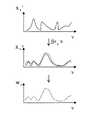
まず、数式4で示される原画像と出力画像の周波数分布について説明する。このときの入力画像ベクトルxνが図6(a)で示されるような分布を有すると仮定する(周波数成分は複素数であるが、ここでは成分の絶対値を示している)。 First, the frequency distribution of the original image and the output image expressed by Equation 4 will be described. It is assumed that the input image vector x ν at this time has a distribution as shown in FIG. 6A (the frequency component is a complex number, but here shows the absolute value of the component).
この入力画像ベクトル(被写体)を完全に推定することは実際には不可能であるが、出力画像の周波数分布に基づいて、入力画像ベクトルのおおよその範囲を推定することは可能である。 Although it is actually impossible to completely estimate the input image vector (subject), it is possible to estimate the approximate range of the input image vector based on the frequency distribution of the output image.
そして、本実施例では図6(a)に示す推定された入力画像ベクトルの成分よりも0.01だけ大きな値に推定範囲の上限があるとして、この上限値分布を基に図6(b)に示すような重み付け成分を行列として抽出する。この結果を用いて数式4を以下のように変形する。 In this embodiment, it is assumed that there is an upper limit of the estimation range at a value larger by 0.01 than the estimated input image vector component shown in FIG. 6A. Based on this upper limit value distribution, FIG. Are extracted as a matrix. Using this result, Equation 4 is transformed as follows.
![]()
![]()
なお、入力画像ベクトルxνの座標系の基底ベクトルは周波数基底行列Fの列ベクトルであったため、xvirの座標系の基底ベクトルは行列FMの列ベクトルとなる。行列FMは行列Mの対角成分の重み付け分布に従って各基底ベクトル成分の絶対値を抑制した行列であり、仮想入力座標系4は、この行列FMにより物体座標系3に変換できる。
Since the base vector of the coordinate system of the input image vector x ν is a column vector of the frequency base matrix F, the base vector of the coordinate system of x vir is a column vector of the matrix FM. The matrix FM is a matrix in which the absolute value of each base vector component is suppressed according to the weighted distribution of the diagonal components of the matrix M, and the virtual input coordinate system 4 can be converted to the object coordinate
いくつかの基底ベクトルが十分に抑制されている場合には、行列FMが構成する座標系はノルムが抑制されていない基底ベクトルで構成される低次元部分空間を近似的に構成することになる。 When some basis vectors are sufficiently suppressed, the coordinate system formed by the matrix FM approximately constitutes a low-dimensional subspace composed of basis vectors whose norms are not suppressed.
このように仮想入力座標系4を選択したとき、行列Sの特異値分解では、図5に示される発信座標系13の次元数を削減した時と同じような効果が得られる。ノルムが抑制されていない基底ベクトルの数を発信座標系13の有効次元数とすると、受信座標系14の次元数との差が小さくなり、被写体が持つ情報の大部分が信号成分として伝達される。このため、原画像構成情報の復元精度が向上し、エリアジングノイズの抑制効果が高まることになる。
When the virtual input coordinate system 4 is selected in this way, the singular value decomposition of the matrix S provides the same effect as when the number of dimensions of the transmission coordinate
本実施例では、入力画像データ(被写体)に対して、このように求められた第1の入力画像データ(仮想入力座標系4)から出力座標系1への変換行列Sと、仮想入力座標系4から目標座標系2への変換行列Siとを求め、変換行列Sの一般逆行列S-gと変換行列Siにより、出力座標系1から目標座標系2への変換行列、つまり補間行列Hを求める。
In the present embodiment, for the input image data (subject), the transformation matrix S from the first input image data (virtual input coordinate system 4) thus determined to the output coordinate
言い換えれば、仮想入力座標系4と、仮想入力座標系4から出力座標系1への変換行列の一般逆行列を利用するとともに、仮想入力座標系4は、入力画像データベクトルを表わす座標系の基底ベクトルに対し,入力画像データベクトル(被写体)の周波数分布の推定に従った重み付けをかけた座標系となるので、複数の基底ベクトルのノルムが抑制される。このため、仮想入力座標系4を用いることで、一般逆行列による画像復元精度が向上し、エリアジングノイズを抑制することが可能となる。
In other words, the virtual input coordinate system 4 and the general inverse matrix of the transformation matrix from the virtual input coordinate system 4 to the output coordinate
なお、本実施例の仮想入力座標系4は、特定の被写体の周波数分布を基にして重み付け行列Mを抽出したが、例えば、複数の被写体が属する周波数範囲を推定し、その範囲の上限を用いてもよい。しかし、この場合には複数の被写体に対して有効な補間行列を生成できるが、仮想入力座標系14の基底ベクトルの絶対値を抑制できる割合が低下するので、エリアジング抑制性能は低減されることになる。
The virtual input coordinate system 4 of this embodiment extracts the weighting matrix M based on the frequency distribution of a specific subject. For example, the frequency range to which a plurality of subjects belong is estimated and the upper limit of the range is used. May be. However, in this case, an effective interpolation matrix can be generated for a plurality of subjects, but since the rate at which the absolute value of the basis vector of the virtual input coordinate
また、被写体の周波数分布を用いずに、画像圧縮等で扱われる各種ウェーブレット変換や離散コサイン変換を行った分布に基づいて重み付け行列Mを抽出してもよい。これらの変換を用いたとき、画像の表現に必要なベクトル成分が少数になり、エリアジング抑制性能の向上がさらに期待できる。 Further, the weighting matrix M may be extracted based on a distribution obtained by performing various wavelet transforms or discrete cosine transforms handled by image compression or the like without using the frequency distribution of the subject. When these transformations are used, the number of vector components required for image representation is reduced, and further improvement in aliasing suppression performance can be expected.
また、出力座標系1、目標座標系2の選択は任意であるが、目標座標系2で解像度が大きく向上するような選択は避けることが望ましい。これは上記方法により仮想入力座標系4の次元を減らせるが、画像で取得していない高周波成分の推定は困難であり、解像度を大きく向上させることは原理的に困難であるからである。
Further, the selection of the output coordinate
本発明の実施例2は、上記実施例1よりもエリアジングノイズ抑制効果を高めた補間方法であり、本実施例の補間処理手順は、図1に示したものと同じであるが、座標系の選択方法が異なる。なお、その他の構成及び処理手順は上記実施例1と同様である。 The second embodiment of the present invention is an interpolation method that has a higher aliasing noise suppression effect than the first embodiment, and the interpolation processing procedure of the present embodiment is the same as that shown in FIG. The selection method is different. Other configurations and processing procedures are the same as those in the first embodiment.
図7は本実施例における座標系と変換行列の関係図である。連結出力座標系21は、同一の被写体に対する複数の出力画像、又は異なる色フィルタ(RGB)から推定した画像を表わす多次元ベクトルを連結したベクトルの座標系である。例として、画素数Nの三つの出力画像を画素座標系で表現して連結したベクトルxlin´は次式のように与えられる。
FIG. 7 is a diagram showing the relationship between the coordinate system and the transformation matrix in this embodiment. The connected output coordinate
![]()
![]()
そして、本実施例の補間処理では連結出力座標系21を上記実施例1における出力座標系1として扱う。目標座標系22、物体座標系23、仮想入力座標系24は上記実施例1の目標座標系2、物体座標系3、仮想入力座標系4に対応する座標系である。
In the interpolation processing of this embodiment, the connected output coordinate
本実施例の仮想入力座標系24の選択方法では、物体座標系23から連結出力座標系21への写像So(物体座標系から出力座標系への変換データ、言い換えると、被写体の存在する座標系から、CCD等の光電変換素子から出力される出力座標系への変換行列)の導出を数式11に従って行う。尚、ここで、Soには、撮影する際の撮像光学系の収差情報等(撮影した際に撮像装置に取り付けられていた撮像光学系の収差情報等)が含まれている。
In the selection method of the virtual input coordinate
![]()
![]()
![]()
![]()
そして、目標座標系22への写像Siは任意に決定できるため、得られた写像Sを基にして補間行列H=S-gSiを生成することができる。
Since the mapping S i to the target coordinate
本実施例では、出力座標系1を連結させて次元数を増加させた連結出力座標系21を用いている。これにより、入力座標系と連結出力座標系の次元数の差を少なくすることができ、エリアジングノイズの抑制効果を向上させることができる。
In this embodiment, a connected output coordinate
なお、連結出力座標系21の次元数を増加させるためには、各出力座標系への写像So (i)の列ベクトルが、他の写像So (j)の列ベクトルに対して高い直交性を持つ必要がある。このような出力座標系の連結処理に基づく画像復元方法を応用した撮像系は、複数回撮像した結果を組み合わせる方式の撮像系として、従来から複数提案されているが、この方式の欠点は、出力座標系の次元数を増加させるために、短時間に多数の画像を条件を変えて取得しなければならないことである。
In order to increase the number of dimensions of the coupled output coordinate
しかし、本実施例では、有効次元数の小さい仮想入力座標系24を用いるため、画像連結のみを用いた方法と比較して必要画像数が少なくてすむ利点がある。
However, since the virtual input coordinate
さらに、重み行列Mの選択としては、上記以外にもいくつかの方法が考えられる。例えば、上記実施例1と同様に複数被写体への対応と周波数変換以外のウェーブレット変換等を用いてもよい。また、連結する出力画像の周波数分布の上限値を用いるかわりに、図9に示すように物体座標系23から連結出力座標系21への写像Soの一般逆行列So -gを用いる方法が考えられる。一般逆行列So -gにより取得した周波数分布は、エリアジングノイズを含むが、連結出力座標系21を構成する各出力画像よりは解像度が高い。このため、So -gにより取得した分布の上限値を用いることで有効性の高い重み付け分布が抽出できる。
In addition to the above, several methods are conceivable for selecting the weight matrix M. For example, as in the first embodiment, correspondence to a plurality of subjects, wavelet transformation other than frequency transformation, and the like may be used. Further, instead of using the upper limit value of the frequency distribution of the output image to be connected, a method using a general inverse matrix S o -g of the mapping S o from the object coordinate
このように本実施例によれば、撮像系により取得した複数の出力画像から連結出力座標系21を求め、目標座標系22、仮想入力座標系24を適切に設定することで、上記実施例1で示した補間処理よりさらにエリアジングノイズ抑制効果の高い補間行列を生成することが可能となる。
As described above, according to the present embodiment, the connection output coordinate
本発明の実施例3は、上記実施例1における補間処理方法を補間処理プログラムとして実行可能に実装した撮像装置である。本実施例では、光電変換して得られた出力画像から重み付け分布(周波数分布)を生成して、撮像装置内の座標変換行列生成回路45において補間行列Hを生成する。図10は本実施例における撮像装置の構成ブロック図である。
The third embodiment of the present invention is an imaging apparatus in which the interpolation processing method in the first embodiment is mounted so as to be executable as an interpolation processing program. In this embodiment, a weight distribution (frequency distribution) is generated from an output image obtained by photoelectric conversion, and an interpolation matrix H is generated in a coordinate conversion
撮影レンズ系41により得られた被写体からの光強度分布を受光素子42で受光する。この受光素子42で得られたアナログ信号をA/D変換回路43によりデジタル化し、メモリ44に記憶する。ここで、撮影レンズ系(撮像光学系)と、CCD等の受光素子とが、画像データ取得手段(被写体像を光電変換して画像データを得る手段)を構成している。
The light intensity distribution from the subject obtained by the photographing
次に、メモリ44から局所画像を取得して座標変換行列生成回路45に出力する。ここで、座標変換行列とは、上記実施例1における仮想入力座標系(空間)4から出力座標系1への写像Sと、仮想入力座標系4から目標座標系2への写像Siのことを示している。
Next, a local image is acquired from the
そして、座標変換行列と局所画像を行列演算回路46に出力し、行列演算を行うことにより局所画像の補間結果を得て、画像合成回路47により局所的な補間結果を組み合わせることで出力画像を得る。画像の分解、合成および座標変換行列生成回路45から行列演算回路46へのデータの流れの制御は補間処理コントローラー48からの制御信号に従って行う。補間処理コントローラー48の動作はプログラムメモリ49によって設定できる。
Then, the coordinate transformation matrix and the local image are output to the
ここで、座標変換行列生成回路45の詳細な構成ブロック図を図11に示す。座標変換対象となる出力座標系1と目標座標系2には画素座標系を用い、仮想入力座標系4は、ウェーブレット変換した座標系に重み付けを加えたものを用いる。ウェーブレット変換は、信号処理や画像圧縮に用いられる変換であり、正規直交性を有する変換から双直交性しか持たない変換まで様々な種類のものが存在し、任意に選ぶことが可能である。ウェーブレット変換した座標系では、少ないベクトル成分で画像を表現できることが知られている。したがって、この座標系を用いることで、重み付け分布で考慮するベクトル成分数を減らせることができるため、高い次元圧縮効果が期待できる。
Here, a detailed block diagram of the coordinate transformation
このように構成された座標変換行列生成回路45では、データフローコントローラー部411が補間処理コントローラー48からの制御信号に従ってデータ転送経路を変更する。メインメモリ44から取得した局所画像データは、一時記憶メモリ412に転送され、一時記憶メモリ412に記憶された局所画像データをウェーブレット変換部413により変換し、変換後の局所画像を重み付け分布生成部414に出力する。
In the coordinate transformation
重み付け分布生成部414では、局所画像のウェーブレット変換分布の絶対値に対し、上記実施例1の図6(b)で示したような変換分布全体を覆う重み付け分布を抽出する。この重み付け分布は行列生成部416に送信され、結果として得られた行列成分が一時記憶メモリ412に格納される。
The weighting
この行列生成部416では、基本行列データ保存用メモリ415に保存されている行列So'、 Soi'の各行ベクトルに対し、重み付け分布生成部414で得られた重み付けを積算する。
In the matrix generation unit 416, the weights obtained by the weight
ここで、行列So'、Soi'は、上記実施例1における物体座標系3から出力座標系1への変換行列であるSoと目標座標系2への変換行列であるSoiとに対し、次式の処理を施した行列である。
Here, the matrices S o ′ and S oi ′ are expressed as S o which is a transformation matrix from the object coordinate
![]()
![]()
また、一般逆行列の生成には、特異値分解を直接的に使用してもよいが、計算量が大きくなるため、本実施例では、重み付け行列による次元圧縮量が小さい場合には、以下の式に従って計算できる。 In addition, singular value decomposition may be used directly for generating the general inverse matrix. However, since the calculation amount increases, in this embodiment, when the dimensional compression amount by the weighting matrix is small, the following It can be calculated according to the formula.
![]()
![]()
![]()
![]()
そして、最終的に得られた一般逆行列So''-gと一時記憶メモリ412に保存されている行列Soi''から補間行列H=Soi'' So''-gを生成する。
Then, an interpolation matrix H = S oi ″ S o ″ -g is generated from the finally obtained general inverse matrix S o ″ -g and the matrix Soi ″ stored in the
このように本実施例では、上記実施例1、2の補間処理プログラムを実行可能に撮像装置に実装し、撮影時に得られる撮像系からの出力画像から被写体の重み付けを推定して補間行列Hを生成する、このため、高いエリアジングノイズ抑制効果を有する撮像装置を提供することが可能となる。 As described above, in this embodiment, the interpolation processing programs of the first and second embodiments are implemented in the imaging apparatus, and the weighting of the subject is estimated from the output image from the imaging system obtained at the time of shooting, and the interpolation matrix H is obtained. Therefore, it is possible to provide an imaging device having a high aliasing noise suppression effect.
本発明の実施例4は、上記実施例3のように、撮像系からの出力画像ごとに被写体の重み付けを行わずに、事前に被写体の重み付け分布を設定する。つまり、画像取得前に補間行列Hをメモリ等に格納しておく。このように上記実施例1、2の補間処理方法により生成された補間行列Hを事前に格納しておくことで画像取得後の計算量を低減できる。なお、その他の構成及び処理手順は上記実施例3と同様である。 In the fourth embodiment of the present invention, the subject weight distribution is set in advance without subject weighting for each output image from the imaging system as in the third embodiment. That is, the interpolation matrix H is stored in a memory or the like before image acquisition. Thus, the amount of calculation after image acquisition can be reduced by storing the interpolation matrix H generated by the interpolation processing method of the first and second embodiments in advance. Other configurations and processing procedures are the same as those in the third embodiment.
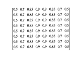
また、本実施例の重み付け分布の推定は、被写体の周波数の方向依存性に着目したものを採用する。被写体が持つ周波数成分が方向に依存している場合には、依存しない方向に対し重み付けをかけることで仮想入力座標系4の有効次元数を低減できる。被写体が人工物体の場合には、方向に依存した周波数成分を多く含むため、この方法が有効になることが多い。y軸方向に周波数分布を持つ場合の重み付け分布の例を図12に示す。このような重み分布で、減衰する方向と減衰量を変化させたものを複数使用する。 In addition, the weighting distribution estimation according to the present embodiment employs a method that pays attention to the direction dependency of the frequency of the subject. When the frequency component of the subject depends on the direction, the effective dimension number of the virtual input coordinate system 4 can be reduced by weighting the direction that does not depend on the direction. When the subject is an artificial object, this method is often effective because it contains many frequency components depending on the direction. FIG. 12 shows an example of the weighting distribution when there is a frequency distribution in the y-axis direction. A plurality of weight distributions having different attenuation directions and attenuation amounts are used.
また、本実施例においても補間行列生成処理では、出力座標系1と目標座標系2には画素座標系を用い、仮想入力座標系4には周波数座標系に上記重み付けをかけた座標系を用いている。
Also in this embodiment, in the interpolation matrix generation process, a pixel coordinate system is used for the output coordinate
図13は、本実施例の撮像装置の構成ブロック図である。撮影レンズ系31により得られた被写体の光強度分布を受光素子32で受光し、得られたアナログ信号をA/D変換回路33によりデジタル化し、メモリ34に記憶する。次に、補間処理コントローラー38により生成した制御信号により、メモリ34、補間行列選択回路35、行列演算回路36、画像合成回路37の制御を行う。補間処理コントローラー38における制御手順はプログラムメモリ39にあらかじめプログラムされたものである。
FIG. 13 is a configuration block diagram of the imaging apparatus of the present embodiment. The light intensity distribution of the subject obtained by the photographing
そして、本実施例の補間処理では、撮像系出力画像内のm×m画素の局所領域に対して、補間行列選択回路35により選択された補間行列を適用する。このとき、補間後の局所画像の周辺部分における画素値の減衰が問題になるが、ここでは、図14に示すように局所領域をs画素ずつ重複した状態で選択し、補間後の中心部分の(m−s)×(m−s)
画素を適用することで正確な値を取得している。
In the interpolation processing of this embodiment, the interpolation matrix selected by the interpolation
Accurate values are obtained by applying pixels.
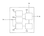
次に、補間処理コントローラー38での制御フローについて説明する。図15は補間行列選択回路35の構成ブロック図である。まず、メモリ34から局所画像を抽出し、補間行列選択回路35に出力する。内部メモリ311は重み付け分布と、該重み付け分布に対応する補間行列を格納している。抽出された局所画像は一時記憶メモリ312に記憶された後、周波数変換部313、比較部314の順に送出され、周波数変換部313では、局所画像の周波数分布を生成し、比較部314で重み付け分布と局所画像の周波数分布の絶対値の比較処理を行う。この比較処理では、次式で与えられる比較値Wを生成する。
Next, a control flow in the
![]()
![]()
続いて、選択された補間行列(画像データに基づいて選択された補間行列、補間データ)と局所画像を行列演算回路36に送出して積算処理を行うとともに、局所画像の補間結果を画像合成回路37で合成し、補間処理後の補間画像として出力とする。
Subsequently, the selected interpolation matrix (interpolation matrix selected based on the image data, interpolation data) and the local image are sent to the
このように本実施例では、あらかじめ準備した重み付け分布に対して作成した補間行列Hにより補間処理を行うので、上記実施例3に比べて補間行列生成処理を画像取得時に行わないため、画像取得後の計算量を低減、言い換えれば、処理負荷及び処理速度が向上する。このため、より好適な補間処理を行うことが可能な撮像装置を実現できる。 As described above, in the present embodiment, the interpolation process is performed by using the interpolation matrix H created for the weight distribution prepared in advance. Therefore, the interpolation matrix generation process is not performed at the time of image acquisition as compared with the third embodiment. The calculation load is reduced, in other words, the processing load and the processing speed are improved. For this reason, the imaging device which can perform a more suitable interpolation process is realizable.
また、上記実施例では、補間処理方法を補間処理プログラムとして撮像装置で実行可能に構成しているが、例えば、画像処理装置の一部、又は別体の補間処理装置として構成することも可能である。具体的には、被写体情報(周波数分布又は重み付け行列)を推定する被写体情報推定部と、この被写体情報に基づいて仮想入力座標系(第1の入力画像データ)4を生成する仮想入力画像生成部と、仮想入力座標系4から画像データへの第1の変換行列Sを生成するとともに、仮想入力座標系4から補間処理後の補間画像データへの第2の変換行列Siを生成する変換行列生成部と、第1及び第2の変換行列S、Siを用いて補間行列Hを生成する補間行列生成部と、補間行列Hを用いて補間処理を行う制御部とで補間処理装置(回路)を構成し、画像処理の処理フローで補間処理を行うように構成することも可能である。 In the above-described embodiment, the interpolation processing method is configured to be executed by the imaging apparatus as an interpolation processing program. However, for example, it may be configured as a part of the image processing apparatus or as a separate interpolation processing apparatus. is there. Specifically, a subject information estimation unit that estimates subject information (frequency distribution or weighting matrix), and a virtual input image generation unit that generates a virtual input coordinate system (first input image data) 4 based on the subject information. A first conversion matrix S from the virtual input coordinate system 4 to the image data, and a second conversion matrix S i from the virtual input coordinate system 4 to the interpolated image data after the interpolation processing a generation unit, the first and second transformation matrix S, an interpolation matrix generation unit which generates an interpolation matrix H using a S i, interpolation processing unit (circuit and a control unit for performing an interpolation process using the interpolation matrix H It is also possible to configure such that interpolation processing is performed in the processing flow of image processing.
なお、本発明を実施し得る形態としては、さらに以下のようなものが挙げられる。 In addition, as a form which can implement this invention, the following are further mentioned.
(1)撮像系の出力画像データベクトルに対して,補間行列を積算することにより補間処理を行う補間処理方法であって,該補間行列は、撮像系の入力画像データベクトルを表現する座標系を決定する第1のステップと、該座標系における入力画像データの分布を推定する第2のステップと、該推定分布と該座標系の基底ベクトルを用いて仮想入力座標系を構成する第3のステップと、該仮想入力座標系から該出力画像データベクトルの座標系への変換行列の一般逆行列を求める第4のステップと、該仮想入力座標系から補間結果の画像データベクトルを表現する座標系への変換行列と該一般逆行列を用いて該補間行列を求める第5のステップに従って生成されることを特徴とする補間方法。 (1) An interpolation processing method for performing interpolation processing by adding up an interpolation matrix to an output image data vector of an imaging system, the interpolation matrix representing a coordinate system representing an input image data vector of the imaging system A first step of determining, a second step of estimating a distribution of input image data in the coordinate system, and a third step of configuring a virtual input coordinate system using the estimated distribution and a basis vector of the coordinate system A fourth step of obtaining a general inverse matrix of a transformation matrix from the virtual input coordinate system to the coordinate system of the output image data vector, and from the virtual input coordinate system to a coordinate system expressing the image data vector of the interpolation result An interpolation method characterized by being generated according to a fifth step of obtaining the interpolation matrix using the transformation matrix and the general inverse matrix.
(2)第1のステップで決定する座標系の基底ベクトルはユニタリ行列を構成することを特徴とする(1)に記載の補間処理方法。 (2) The interpolation processing method according to (1), wherein the basis vector of the coordinate system determined in the first step constitutes a unitary matrix.
(3)ユニタリ行列がフーリエ変換行列であることを特徴とする(2)に記載の補間処理方法。 (3) The interpolation processing method according to (2), wherein the unitary matrix is a Fourier transform matrix.
(4)ユニタリ行列が直交ウェーブレット変換に分類される行列であることを特徴とする(2)に記載の補間処理方法。 (4) The interpolation processing method according to (2), wherein the unitary matrix is a matrix classified into orthogonal wavelet transform.
(5)第1のステップで決定する座標系の基底ベクトルは双直交ウェーブレット変換に分類される行列であることを特徴とする(1)に記載の補間処理方法。 (5) The interpolation processing method according to (1), wherein the basis vector of the coordinate system determined in the first step is a matrix classified into a bi-orthogonal wavelet transform.
上記(1)に係る実施形態では、仮想入力座標系と、仮想入力座標系から出力座標系への変換行列の一般逆行列を利用する。仮想入力座標系は、入力画像データベクトルを表わす座標系の基底ベクトルに対し、入力画像データベクトルの推定分布に従った重みをかけた座標系であり、複数の基底ベクトルのノルムが抑制されている。このように仮想入力座標系を用いることで、一般逆行列による画像復元精度が向上し、エリアジングノイズを抑制できる。 In the embodiment according to (1) above, a virtual input coordinate system and a general inverse matrix of a transformation matrix from the virtual input coordinate system to the output coordinate system are used. The virtual input coordinate system is a coordinate system obtained by applying a weight according to the estimated distribution of the input image data vector to the basis vector of the coordinate system representing the input image data vector, and the norm of the plurality of base vectors is suppressed. . By using the virtual input coordinate system in this way, the image restoration accuracy by the general inverse matrix is improved, and aliasing noise can be suppressed.
また、上記(1)から(5)に係る実施形態では、入力画像データベクトルを表わす座標系の選択方法を変えて、(1)の補間処理方法のエリアジングノイズ抑制効果を高めたものである。エリアジングノイズを含む出力画像は、入力画像の周波数成分が混在した状態になっているので、入力画像データを出力画像データを用いて推定する場合に、座標系の選択により推定精度が変化する。そこで、上記(2)から(5)は、決まった座標系に対して入力画像データを推定する手法であり、各々の座標系で情報が正確に取得できている場合にエリアジングノイズの抑制効果を高めることができる。 In the embodiments according to the above (1) to (5), the selection method of the coordinate system representing the input image data vector is changed to enhance the aliasing noise suppressing effect of the interpolation processing method of (1). . Since the output image including aliasing noise is in a state in which the frequency components of the input image are mixed, when the input image data is estimated using the output image data, the estimation accuracy varies depending on the selection of the coordinate system. Therefore, the above (2) to (5) are methods for estimating the input image data with respect to a fixed coordinate system, and the effect of suppressing aliasing noise when information can be accurately acquired in each coordinate system. Can be increased.
1 出力座標系
2 目標座標系
3 物体座標系
4 仮想入力座標系
H 補間行列
S 変換行列
1 Output coordinate
Claims (12)
被写体情報を推定する第1のステップと、
前記被写体情報に基づいて第1の入力画像データを生成する第2のステップと、
前記第1の入力画像データから前記画像データへの第1の変換データを生成する第3のステップと、
前記第1の入力画像データから補間処理後の補間画像データへの第2の変換データを生成する第4のステップと、
前記第1及び第2の変換データを用いて前記補間データを生成する第5のステップとを有することを特徴とする補間処理方法。 An interpolation processing method for performing interpolation processing using interpolation data for image data obtained by photoelectrically converting a subject image,
A first step of estimating subject information;
A second step of generating first input image data based on the subject information;
A third step of generating first conversion data from the first input image data to the image data;
A fourth step of generating second conversion data from the first input image data to interpolated image data after interpolation processing;
And a fifth step of generating the interpolation data using the first and second conversion data.
被写体情報を推定する第1のステップと、
前記被写体情報に基づいて第1の入力画像データを生成する第2のステップと、
前記第1の入力画像データから前記画像データへの第1の変換データを生成する第3のステップと、
前記第1の入力画像データから補間処理後の補間画像データへの第2の変換データを生成する第4のステップと、
前記第1及び第2の変換データを用いて前記補間データを生成する第5のステップとを有することを特徴とする補間処理プログラム。 An interpolation processing program for performing interpolation processing using interpolation data for image data obtained by photoelectrically converting a subject image,
A first step of estimating subject information;
A second step of generating first input image data based on the subject information;
A third step of generating first conversion data from the first input image data to the image data;
A fourth step of generating second conversion data from the first input image data to interpolated image data after interpolation processing;
And a fifth step of generating the interpolation data using the first and second conversion data.
前記補間データを用いて補間処理を行う制御手段とを有することを特徴とする撮像装置。 Interpolation data generating means for generating the interpolation data based on the interpolation processing program according to any one of claims 4 to 6,
An image pickup apparatus comprising: a control unit that performs an interpolation process using the interpolation data.
前記制御手段が前記画像データに対して補間処理を行うことを特徴とする請求項7に記載の撮像装置。 Image data acquisition means for photoelectrically converting a subject image to acquire image data;
The imaging apparatus according to claim 7, wherein the control unit performs an interpolation process on the image data.
前記補間データを用いて補間処理を行う制御手段とを有することを特徴とする撮像装置。 Storage means for storing the interpolation data generated by the interpolation processing program according to any one of claims 4 to 6;
An image pickup apparatus comprising: a control unit that performs an interpolation process using the interpolation data.
前記制御手段が前記画像データに対して補間処理を行うことを特徴とする請求項9に記載の撮像装置。 Image data acquisition means for photoelectrically converting a subject image to acquire image data;
The imaging apparatus according to claim 9, wherein the control unit performs an interpolation process on the image data.
前記制御手段が、前記複数種類の補間データのうち、前記画像データに基づいて少なくとも1つの補間データを選択し、選択された前記補間データを用いて前記画像データに対して補間処理を行うことを特徴とする請求項10に記載の撮像装置。 The storage means stores a plurality of types of interpolation data generated by the interpolation processing program,
The control means selects at least one interpolation data based on the image data from the plurality of types of interpolation data, and performs an interpolation process on the image data using the selected interpolation data. The imaging apparatus according to claim 10, wherein the imaging apparatus is characterized.
被写体情報を推定する被写体情報推定手段と、
前記被写体情報に基づいて第1の入力画像データを生成する入力画像データ生成手段と、
前記第1の入力画像データから前記画像データへの第1の変換データを生成するとともに、前記第1の入力画像データから補間処理後の補間画像データへの第2の変換データを生成する変換データ生成手段と、
前記第1及び第2の変換データを用いて前記補間データを生成する補間データ生成手段と、
前記補間データを用いて補間処理を行う制御手段とを有することを特徴とする補間処理装置。 An interpolation processing device that performs interpolation processing using interpolation data for image data obtained by photoelectrically converting a subject image,
Subject information estimation means for estimating subject information;
Input image data generation means for generating first input image data based on the subject information;
Conversion data for generating first conversion data from the first input image data to the image data and generating second conversion data from the first input image data to interpolation image data after interpolation processing Generating means;
Interpolation data generating means for generating the interpolation data using the first and second conversion data;
An interpolation processing apparatus comprising control means for performing an interpolation process using the interpolation data.
Priority Applications (2)
| Application Number | Priority Date | Filing Date | Title |
|---|---|---|---|
| JP2005010032A JP2006203296A (en) | 2005-01-18 | 2005-01-18 | Interpolation processing method, interpolation processing program, and imaging apparatus |
| US11/335,423 US7693351B2 (en) | 2005-01-18 | 2006-01-18 | Interpolation processing method, interpolation processing program, and imaging apparatus |
Applications Claiming Priority (1)
| Application Number | Priority Date | Filing Date | Title |
|---|---|---|---|
| JP2005010032A JP2006203296A (en) | 2005-01-18 | 2005-01-18 | Interpolation processing method, interpolation processing program, and imaging apparatus |
Publications (2)
| Publication Number | Publication Date |
|---|---|
| JP2006203296A true JP2006203296A (en) | 2006-08-03 |
| JP2006203296A5 JP2006203296A5 (en) | 2008-03-06 |
Family
ID=36683959
Family Applications (1)
| Application Number | Title | Priority Date | Filing Date |
|---|---|---|---|
| JP2005010032A Abandoned JP2006203296A (en) | 2005-01-18 | 2005-01-18 | Interpolation processing method, interpolation processing program, and imaging apparatus |
Country Status (2)
| Country | Link |
|---|---|
| US (1) | US7693351B2 (en) |
| JP (1) | JP2006203296A (en) |
Families Citing this family (8)
| Publication number | Priority date | Publication date | Assignee | Title |
|---|---|---|---|---|
| TWI524773B (en) * | 2009-10-23 | 2016-03-01 | 財團法人資訊工業策進會 | Detection apparatus, detection method and computer program product thereof for detecting an object in real-time |
| JP5410355B2 (en) | 2010-04-13 | 2014-02-05 | 富士フイルム株式会社 | Matrix generation apparatus, method, program, and information processing apparatus |
| JP5524692B2 (en) * | 2010-04-20 | 2014-06-18 | 富士フイルム株式会社 | Information processing apparatus and method, and program |
| RU2013100160A (en) * | 2013-01-09 | 2014-07-20 | ЭлЭсАй Корпорейшн | PROCESSING IMAGES WITH SUPER RESOLUTION USING THE REVERSIBLE RARE SPARED MATRIX |
| US20150074130A1 (en) * | 2013-09-09 | 2015-03-12 | Technion Research & Development Foundation Limited | Method and system for reducing data dimensionality |
| US9349158B2 (en) * | 2014-07-14 | 2016-05-24 | Novatek Microelectronics Corp. | Image interpolation method and image interpolation system |
| JP6818585B2 (en) * | 2017-02-21 | 2021-01-20 | キヤノン株式会社 | Image processing device, image processing method, and program |
| US10229092B2 (en) | 2017-08-14 | 2019-03-12 | City University Of Hong Kong | Systems and methods for robust low-rank matrix approximation |
Family Cites Families (4)
| Publication number | Priority date | Publication date | Assignee | Title |
|---|---|---|---|---|
| JP3583447B2 (en) * | 1992-04-28 | 2004-11-04 | オリンパス株式会社 | Imaging device |
| US6144873A (en) * | 1998-04-17 | 2000-11-07 | Board Of Trustees Of The Leland Stanford Junior University | Method of efficient data encoding in dynamic magnetic resonance imaging |
| JP3707259B2 (en) * | 1998-09-10 | 2005-10-19 | コニカミノルタフォトイメージング株式会社 | Image composition method and image composition apparatus using the method |
| US6950211B2 (en) * | 2001-07-05 | 2005-09-27 | Corel Corporation | Fine moire correction in images |
-
2005
- 2005-01-18 JP JP2005010032A patent/JP2006203296A/en not_active Abandoned
-
2006
- 2006-01-18 US US11/335,423 patent/US7693351B2/en not_active Expired - Fee Related
Also Published As
| Publication number | Publication date |
|---|---|
| US20060159362A1 (en) | 2006-07-20 |
| US7693351B2 (en) | 2010-04-06 |
Similar Documents
| Publication | Publication Date | Title |
|---|---|---|
| JP4214409B2 (en) | High resolution color image generation method, high resolution color image generation apparatus, and high resolution color image generation program | |
| JP6024107B2 (en) | Image processing apparatus, imaging apparatus, image processing method, and program | |
| JP5797016B2 (en) | Image processing apparatus, image processing method, and program | |
| JP5786149B2 (en) | Universally packed pixel array camera system and method | |
| JP5251637B2 (en) | Noise reduction device, noise reduction method, noise reduction program, recording medium | |
| JP2006203296A (en) | Interpolation processing method, interpolation processing program, and imaging apparatus | |
| JP4941285B2 (en) | Imaging apparatus, imaging system, imaging method, and image processing apparatus | |
| JP6672070B2 (en) | Imaging apparatus using compressed sensing, imaging method, and imaging program | |
| KR101633397B1 (en) | Image restoration device, image restoration method and image restoration system | |
| JP2017010092A (en) | Image processing apparatus, imaging device, image processing method, image processing program, and recording medium | |
| JP5765893B2 (en) | Image processing apparatus, imaging apparatus, and image processing program | |
| WO2015098243A1 (en) | Image processing device, image capturing device, program, and image processing method | |
| CN113870110A (en) | Image fusion method and device for remote sensing image, electronic equipment and storage medium | |
| JP5098054B2 (en) | Image processing apparatus and image processing program | |
| JP5718138B2 (en) | Image signal processing apparatus and program | |
| JP2009010847A (en) | Color component interpolation apparatus, and method thereof | |
| JP2012003454A (en) | Image processing apparatus, imaging device and image processing program | |
| JP5672941B2 (en) | Image processing apparatus, image processing method, and program | |
| McElvain et al. | Camera color correction using two-dimensional transforms | |
| KR101243285B1 (en) | Apparatus and method for reconstructing color image based on multi-spectrum using Bayer Color Filter Array camera | |
| JP6541454B2 (en) | Image processing apparatus, imaging apparatus, image processing method, image processing program, and storage medium | |
| JP2016119542A (en) | Image processing method, image processing program, image processing unit, and imaging apparatus | |
| JP6435560B1 (en) | Image processing apparatus, image processing method, program, and imaging apparatus | |
| JP6661491B2 (en) | Image processing apparatus and image processing method | |
| JP2008160210A (en) | Information processing method, and imaging apparatus |
Legal Events
| Date | Code | Title | Description |
|---|---|---|---|
| A521 | Request for written amendment filed |
Free format text: JAPANESE INTERMEDIATE CODE: A523 Effective date: 20080118 |
|
| A621 | Written request for application examination |
Free format text: JAPANESE INTERMEDIATE CODE: A621 Effective date: 20080118 |
|
| RD03 | Notification of appointment of power of attorney |
Free format text: JAPANESE INTERMEDIATE CODE: A7423 Effective date: 20081023 |
|
| RD05 | Notification of revocation of power of attorney |
Free format text: JAPANESE INTERMEDIATE CODE: A7425 Effective date: 20081201 |
|
| A762 | Written abandonment of application |
Free format text: JAPANESE INTERMEDIATE CODE: A762 Effective date: 20100202 |
|
| A977 | Report on retrieval |
Free format text: JAPANESE INTERMEDIATE CODE: A971007 Effective date: 20100204 |