JP2006170827A - Scintillator for detecting radiation - Google Patents
Scintillator for detecting radiation Download PDFInfo
- Publication number
- JP2006170827A JP2006170827A JP2004364250A JP2004364250A JP2006170827A JP 2006170827 A JP2006170827 A JP 2006170827A JP 2004364250 A JP2004364250 A JP 2004364250A JP 2004364250 A JP2004364250 A JP 2004364250A JP 2006170827 A JP2006170827 A JP 2006170827A
- Authority
- JP
- Japan
- Prior art keywords
- scintillator
- inorganic hybrid
- hybrid compound
- perovskite
- organic
- Prior art date
- Legal status (The legal status is an assumption and is not a legal conclusion. Google has not performed a legal analysis and makes no representation as to the accuracy of the status listed.)
- Pending
Links
Images


Abstract
Description
この発明は、γ線、X線、電子線、重荷電粒子線及び中性子線等の電離性放射線の放射線検出装置に関し、更に詳細には、発光の立ちあがりから消滅に至る時間が極めて短く(サブナノ秒オーダー又はそれ以下)、かつ放射線量を測定することのできる放射線検出装置に関する。 The present invention relates to a radiation detection apparatus for ionizing radiation such as γ-rays, X-rays, electron beams, heavy charged particle beams, and neutron beams, and more specifically, the time from the rise of light emission to the extinction thereof is extremely short (sub-nanoseconds). The present invention relates to a radiation detection apparatus that can measure the radiation dose.
電離性放射線の検出や測定には、シンチレーションカウンターが用いられている。特に近年、サブナノ秒の極超短パルス放射線の測定が放射線現場で必要になってきている。
シンチレータには、(i)シンチレーション効率が高く発光量が多いこと、(ii)発光の立ち上がり時間及び減衰時間が短いこと、(iii)耐放射線性が高いこと、及び(iv)好ましくは放射線量を定量できることなどの性能が要求されるが、これらを全て同時に満たすシンチレータ材料は今まで存在しなかった。
従来用いられてきたシンチレーターのうち、NaI(Tl)、CsI(Tl)、ZnS(Ag)などの無機結晶を用いたものでは、発光の立ち上がりから消滅に至る時間がマイクロ(10−6)秒の単位と遅く、ナノ(10−9)秒単位等の短パルス放射線の計測には応答が追いつかないという問題を有していた。一方、アントラセンやナフタリンなどの有機結晶は、上記の時間がナノ秒単位と速いが、蛍光効率が低く発光量が少ないため、測定精度が低く、また耐放射線性が低いため実用に適さないという問題を有していた。
A scintillation counter is used for detection and measurement of ionizing radiation. In particular, in recent years, measurement of sub-nanosecond ultrashort pulse radiation has become necessary in the radiation field.
The scintillator has (i) high scintillation efficiency and a large amount of luminescence, (ii) short rise time and decay time of luminescence, (iii) high radiation resistance, and (iv) preferably a radiation dose. Although performance such as being capable of being quantified is required, there has been no scintillator material that satisfies all of these simultaneously.
Among scintillators that have been used in the past, those using inorganic crystals such as NaI (Tl), CsI (Tl), ZnS (Ag), etc., have a micro (10 −6 ) second time from the rise of light emission to extinction. It has a problem that the response cannot catch up with the measurement of short pulse radiation such as nano (10 −9 ) seconds, which is slow in unit. On the other hand, organic crystals such as anthracene and naphthalene are not suitable for practical use because the above time is as fast as nanoseconds, but the fluorescence efficiency is low and the amount of luminescence is low, so the measurement accuracy is low and the radiation resistance is low. Had.
一方、有機無機層状ペロブスカイト、特に(CnH2n+1NH3)2MX4(式中、nは2〜18の整数、MはCd、Cu、Fe、Mn、Pd又はPb、XはCl、Br又はIを表す。)で表されるビス(アルキルアンモニウム)金属(II)テトラハライドの構造や特性は詳しく研究されている(非特許文献1、2)。特に、(CnH2n+1NH3)2PbI4(式中、nは4〜14を表す。)で表される有機無機層状ペロブスカイトの構造は詳しく調べられており、低次元量子開じ込め構造に由来して、安定で強力な励起子発光を示すことが知られており(非特許文献3)、紫外線を照射した場合に無機層であるPbI4層の電子遷移によって可視領域で発光すること等興味深い知見が得られている。
本発明者らは既に、このような量子閉じ込め構造を有するペロブスカイト型有機無機ハイブリッド化合物の励起子発光の放射耐性が高いことを見出し、更にこのようなペロブスカイト型有機無機ハイブリッド化合物が超短パルス電離放射線の検出や放射線量測定用シンチレータに用いることができることを見出した(特許文献1)。
On the other hand, organic / inorganic layered perovskite, particularly (C n H 2n + 1 NH 3 ) 2 MX 4 (where n is an integer of 2 to 18, M is Cd, Cu, Fe, Mn, Pd or Pb, X is Cl, Br) The structure and properties of the bis (alkylammonium) metal (II) tetrahalide represented by (I) are studied in detail (Non-Patent
The present inventors have already found that the perovskite-type organic-inorganic hybrid compound having such a quantum confinement structure has a high exciton emission resistance, and further, such a perovskite-type organic-inorganic hybrid compound has an ultrashort pulse ionizing radiation. It has been found that it can be used for scintillators for detection and radiation dose measurement (Patent Document 1).
ガンマ線などの放射線の検出のために、実装が容易で、可視光を発光し、検出効率が大きく、製造設備が簡単で、高速なシンチレーターが求められている。特に、医療におけるPET(Positron Emission Tomography: 陽電子断層撮影)に使用するには、実装が容易で可視光を発光することと、ガンマ線の検出効率が大きいことが重要な要件になっている。 特許文献1に記載のペロブスカイト型有機無機ハイブリッド化合物から成るシンチレータは、イオンビーム、中性子線、低エネルギーX線の測定等には支障はないが、このペロブスカイト型化合物には厚い単結晶の育成が困難であるという問題がある。特に、高エネルギーγ線のような透過力の高い放射線については、結晶が薄いため結晶と作用せずに透過する確率が増えて検出率が低下するという問題があった。
For detection of radiation such as gamma rays, there is a need for a scintillator that is easy to mount, emits visible light, has high detection efficiency, has simple manufacturing facilities, and is high-speed. In particular, for use in medical PET (Positron Emission Tomography), mounting is easy, emitting visible light, and high gamma-ray detection efficiency are important requirements. The scintillator comprising the perovskite type organic-inorganic hybrid compound described in
このような課題を解決するために,本発明者らは、ガラス容器にトルエン等の有機溶媒中に一定量の上記ペロブスカイト型有機無機ハイブリッド化合物を浸漬し、一定の光路を確保することにより、効果的に放射線を検出することができることを見出した。
即ち、本発明は、ガラス製セルにペロブスカイト型有機無機ハイブリッド化合物及び有機溶媒を封入してなる放射線検出用シンチレーターであって、該ペロブスカイト型有機無機ハイブリッド化合物が一般式
R1−NR2 3)2MX4
(式中、R1は複素環を含んでもよくハロゲン原子で置換されていてもよい一価炭化水素基、R2は、水素又は炭素数2以下のアルキル基、MはIVa族金属、Eu、Cd、Cu、Fe、Mn又はPd、Xはハロゲン原子を表す。)で表され、該有機溶媒に対するペロブスカイト型有機無機ハイブリッド化合物の量が0.03〜3.0g/ccである放射線検出用シンチレーターである。なおこの放射線の光路が0.1〜5.0cmとなるように構成されることが好ましい。
また、本発明は、このシンチレータ及び受光器からなる放射線検出装置である。
In order to solve such a problem, the present inventors have achieved an effect by immersing a certain amount of the perovskite-type organic-inorganic hybrid compound in a glass container in an organic solvent such as toluene, and ensuring a certain optical path. It was found that radiation can be detected automatically.
That is, the present invention is a scintillator for radiation detection in which a perovskite-type organic-inorganic hybrid compound and an organic solvent are enclosed in a glass cell, wherein the perovskite-type organic-inorganic hybrid compound has the general formula R 1 —NR 2 3 ) 2 MX 4
(In the formula, R 1 may contain a heterocyclic ring and may be substituted with a halogen atom, R 2 is hydrogen or an alkyl group having 2 or less carbon atoms, M is a group IVa metal, Eu, Cd, Cu, Fe, Mn or Pd, X represents a halogen atom.) The amount of the perovskite organic-inorganic hybrid compound relative to the organic solvent is 0.03 to 3.0 g / cc. It is. In addition, it is preferable to be comprised so that the optical path of this radiation may be 0.1-5.0 cm.
Moreover, this invention is a radiation detection apparatus which consists of this scintillator and a light receiver.
本発明のシンチレーターは、発光波長が可視光で、任意形状をとれ、原子番号の大きい物質(鉛など)を含み、高い耐放射線を有するため、γ線、X線、電子線、重荷電粒子線及び中性子線等の電離性放射線の検出や線量測定に適している。また、このシンチレータは、大規模製造設備を必要とせずに製造可能であり、高速かつ光量の大きいシンチレーターを容易に提供することができる。更に、このシンチレーターを用いた放射線検出装置は、従来のシンチレーションカウンターでは測定し得なかった、サブナノ秒単位の短パルス電離放射線検出を可能とする。 Since the scintillator of the present invention has an emission wavelength of visible light, can take an arbitrary shape, contains a substance having a large atomic number (such as lead), and has high radiation resistance, γ rays, X rays, electron beams, heavy charged particle beams It is suitable for the detection and dosimetry of ionizing radiation such as neutrons. Moreover, this scintillator can be manufactured without requiring a large-scale manufacturing facility, and a scintillator with high speed and a large amount of light can be easily provided. Furthermore, the radiation detection apparatus using this scintillator enables detection of short pulse ionizing radiation in sub-nanosecond units, which could not be measured by a conventional scintillation counter.
本発明で用いるペロブスカイト型有機無機ハイブリッド化合物は一般式(R1−NR2 3)2MX4 で表される。
R1はハロゲン原子で置換されていてもよい一価炭化水素基であり、直鎖、分枝又は環状でもよく、炭素数は一般に2〜18であり、好ましくはアルキル基、アリール基、又はアラルキル基であり、より好ましくはアルキル基である。アリール基としてはフェニル基が好ましい。アラルキル基としては(C6H5)CnH2n(nは2〜4)が好ましい。またR1はピロール基やチオフェン基等の複素環を含んでもよい。R2は、それぞれ同じか又は異なってもよく、水素又は炭素数2以下のアルキル基、好ましくは水素又はメチル基、より好ましくは水素である。
Xはハロゲン原子を表し、好ましくはCl、Br又はIである。
MはIVa族金属、Eu、Cd、Cu、Fe、Mn又はPdであり、好ましくはIVa族金属又はEu、より好ましくはIVa族金属、更に好ましくはGe、Sn又はPb、最も好ましくはPbである。
The perovskite organic-inorganic hybrid compound used in the present invention is represented by the general formula (R 1 —NR 2 3 ) 2 MX 4 .
R 1 is a monovalent hydrocarbon group which may be substituted with a halogen atom, may be linear, branched or cyclic, and generally has 2 to 18 carbon atoms, preferably an alkyl group, aryl group or aralkyl. Group, more preferably an alkyl group. The aryl group is preferably a phenyl group. As the aralkyl group, (C 6 H 5 ) C n H 2n (n is 2 to 4) is preferable. R 1 may also contain a heterocyclic ring such as a pyrrole group or a thiophene group. R 2 may be the same or different, and is hydrogen or an alkyl group having 2 or less carbon atoms, preferably hydrogen or a methyl group, more preferably hydrogen.
X represents a halogen atom, preferably Cl, Br or I.
M is a group IVa metal, Eu, Cd, Cu, Fe, Mn or Pd, preferably a group IVa metal or Eu, more preferably a group IVa metal, still more preferably Ge, Sn or Pb, most preferably Pb. .
このペロブスカイト型化合物の結晶を作製するには、化合物を有機溶媒(例えば、N,Nジメチルホルムアミド)に高濃度(例えば、室温における溶解度付近)に溶解し、その後溶液の溶解度を徐々に低下させることによって析出させる。このようにして生成する結晶のサイズは通常厚さ0.2mm程度以下である。より大きく良質な結晶(厚さ2.0mm程度以上)を求める場合は、結晶作成時にパラフィルムに開ける穴の大きさを小さくするが、大きくても最大1mm厚程度の結晶しか得ることができない。 In order to produce crystals of this perovskite type compound, the compound is dissolved in an organic solvent (for example, N, N dimethylformamide) at a high concentration (for example, around the solubility at room temperature), and then the solubility of the solution is gradually decreased. To precipitate. The size of the crystal thus produced is usually about 0.2 mm or less. In the case of obtaining a larger and better crystal (thickness of about 2.0 mm or more), the size of the hole opened in the parafilm at the time of crystal production is reduced, but only a crystal having a maximum thickness of about 1 mm can be obtained.
本発明のシンチレータは、上記ペロブスカイト型化合物の微結晶をガラス容器に封入する。
このガラスは、放射線の透過を妨げないように、石英が好ましい。
ガラス容器のサイズと形状は、放射線の光路を0.1〜5cm、好ましくは0.5〜5cm確保することができれば、特に限定はない。
用いる有機溶媒は、(i)蛍光波長に対して透明であり、(ii)上記化合物を溶解したり分解するものでないこと、(iii)上記化合物の屈折率が1.7よりも大きいことから、屈折率が大きいほど光学的な親和性が大きく好ましい、の条件に合うものを用いる。このような有機溶媒として、トルエン、アセトン、ニトロメタンなどを用いることができるが、臭化物ではトルエン(屈折率1.50)とアセトン(屈折率1.35)、沃化物ではトルエンとニトロメタン(屈折率1.38)が好ましい。この中でトルエンは屈折率が高いため好ましい。
The scintillator of the present invention encloses the perovskite-type compound microcrystals in a glass container.
This glass is preferably quartz so as not to prevent the transmission of radiation.
The size and shape of the glass container are not particularly limited as long as the optical path of radiation can be secured 0.1 to 5 cm, preferably 0.5 to 5 cm.
The organic solvent used is (i) transparent to the fluorescence wavelength, (ii) does not dissolve or decompose the compound, and (iii) the compound has a refractive index greater than 1.7, A material that satisfies the condition that the higher the refractive index, the greater the optical affinity is preferable. As such an organic solvent, toluene, acetone, nitromethane and the like can be used. Toluene (refractive index 1.50) and acetone (refractive index 1.35) are used for bromide, and toluene and nitromethane (
ガラス容器は空間がないようにペロブスカイト型化合物と有機溶媒で充填されることが好ましいが、行路以外の部分に不活性ガス(N2、CO2、He、Ne、Kr、Xe等)の空間があってもよい。
この有機溶媒に上記ペロブスカイト型化合物を、有機溶媒に対するペロブスカイト型有機無機ハイブリッド化合物の量が0.03〜3g/cc、好ましくは0.5〜3g/ccとなるように、浸漬する。
The glass container is preferably filled with a perovskite type compound and an organic solvent so that there is no space, but there is a space of inert gas (N 2 , CO 2 , He, Ne, Kr, Xe, etc.) in a portion other than the path. There may be.
The perovskite compound is immersed in this organic solvent so that the amount of the perovskite organic-inorganic hybrid compound relative to the organic solvent is 0.03 to 3 g / cc, preferably 0.5 to 3 g / cc.
本発明の放射線検出装置は、上記シンチレータ及び受光器からなる。このシンチレータは可視域で発光するため、受光器には光電子倍増管を用いるのが好ましい。放射線検出装置の構造に特に制限はなく、例えば、シンチレータが光電子倍増管の受光面に接触した構造(例えば、光電子倍増管の受光面にシンチレータを塗布した構造)、シンチレータと光電子倍増管が導光管で連結されている構造、シンチレータの発光をシンチレータから離れた光電子倍増管で受光する構造、シンチレータの発光をシンチレータから離れた受光ポートで受けてこの受光ポートと光電子倍増管とが導光管で連結されている構造等が挙げられる。受光器の信号は通常の方法で処理される。 The radiation detection apparatus of this invention consists of the said scintillator and a light receiver. Since this scintillator emits light in the visible range, it is preferable to use a photomultiplier tube as the light receiver. There are no particular restrictions on the structure of the radiation detector, for example, a structure in which the scintillator is in contact with the light receiving surface of the photomultiplier tube (for example, a structure in which the scintillator is applied to the light receiving surface of the photomultiplier tube), and the scintillator and the photomultiplier tube guide light. A structure connected by a tube, a structure in which the light emitted from the scintillator is received by a photomultiplier tube separated from the scintillator, and a light receiving port in which the light emitted from the scintillator is received by a light receiving port separated from the scintillator. Examples include a connected structure. The receiver signal is processed in the usual way.
以下、実施例により本発明を例証するが、これらは本発明を制限することを意図したものではない。
製造例1
ハロゲン化金属として臭化鉛PbBr2及び有機アミンハロゲン化水素酸塩としてC6H13NH3Brを1:2のモル比でN,N−ジメチルホルムアミド中で反応させることにより(反応温度:室温(20℃)、反応時間:1時間以上)、層状ペロブスカイト型化合物(C6H13NH3)2PbBr4を合成した。
この層状ペロブスカイト型化合物1gをアセトン3ミリリットル中に溶解させ、島津製作所製 P/N 202-32016(回転数:5000rpm、時間:30秒以上)を用いて、2cm角のシリコン(Si)基板の上にスピンコートし、シンチレータ(層状ペロブスカイト型化合物の厚さ0.1μm)を作製した。得られた結晶は、厚さ0.1mm程度、大きさ1mm2から30mm2のフレーク状であった。
The invention will now be illustrated by the following examples, which are not intended to limit the invention.
Production Example 1
By reacting lead bromide PbBr 2 as a metal halide and C 6 H 13 NH 3 Br as an organic amine hydrohalide salt in a molar ratio of 1: 2, in N, N-dimethylformamide (reaction temperature: room temperature). (20 ° C., reaction time: 1 hour or more), a layered perovskite compound (C 6 H 13 NH 3 ) 2 PbBr 4 was synthesized.
1 g of this layered perovskite type compound is dissolved in 3 ml of acetone, and P / N 202-32016 (rotation speed: 5000 rpm, time: 30 seconds or more) manufactured by Shimadzu Corporation is used on a 2 cm square silicon (Si) substrate. Then, a scintillator (a layered perovskite type compound having a thickness of 0.1 μm) was produced. The obtained crystals were in the form of flakes having a thickness of about 0.1 mm and a size of 1 mm 2 to 30 mm 2 .
この粉末5.0gに7.5mlの脱水DMFを加えて完全に溶解させた。更に貧溶媒である脱水アセトン6.5mlを加えて結晶が析出しない程度に溶解度を低下させ飽和状態に近づけた。得られた無色透明な溶液を、粒子保持能力0.2μmのフィルターで濾過し、未溶解の微結晶や混入した埃などの異物を除去した。予めアルカリ溶液と純水で洗浄しておいた、100mlのサンプル瓶に濾液を移した後、サンプル瓶の口をパラフィルムで覆い、直径3mm程度の穴を二つ開けた。このサンプル瓶が結晶成長容器となる。
これとは、別にサンプル瓶が納まる大きさのデシケータを用意し、100mlのアセトンと10gの塩化カルシウム(脱水剤)を加えた。そのデシケータ内に上記サンプル瓶を入れ、密封・遮光して3週間静置してから開封したところ、サンプル瓶の底部に結晶が約10枚析出していた。典型的なサイズは8mm×5mm×0.3mmであった。これは、デシケータ内で蒸発したアセトンが結晶のDMF溶液へ浸透して、徐々に溶解度を低下させたためと考えられる。
To 5.0 g of this powder, 7.5 ml of dehydrated DMF was added and completely dissolved. Furthermore, 6.5 ml of dehydrated acetone, which is a poor solvent, was added to lower the solubility to such an extent that crystals did not precipitate, and approached saturation. The resulting colorless and transparent solution was filtered through a filter having a particle retention capacity of 0.2 μm to remove foreign matters such as undissolved fine crystals and mixed dust. After the filtrate was transferred to a 100 ml sample bottle that had been washed with an alkaline solution and pure water in advance, the mouth of the sample bottle was covered with parafilm and two holes with a diameter of about 3 mm were made. This sample bottle becomes a crystal growth vessel.
Separately, a desiccator of a size that can accommodate a sample bottle was prepared, and 100 ml of acetone and 10 g of calcium chloride (dehydrating agent) were added. The sample bottle was placed in the desiccator, sealed and shielded from light, allowed to stand for 3 weeks, and then opened. As a result, about 10 crystals were deposited on the bottom of the sample bottle. The typical size was 8mm x 5mm x 0.3mm. This is thought to be because acetone evaporated in the desiccator permeated into the DMF solution of crystals and gradually lowered the solubility.
内径20mm、厚さ8mmのガラス製セルに、製造例1で得た結晶を0.8g封入し、隙間をトルエンで満たした。
ガンマ線計測は、図1に示すように、Ge-68から同時に2本放出される、陽電子消滅ガンマ線(エネルギー511keV)をガンマ線検出器AとBで捕らえた。
上記のガラスセルにフッ素樹脂製反射材を巻きつけ、これを光電子増倍管(浜松ホトニクス製H3378)にシリコングリスで貼り付けて、ガンマ線検出器Aとした。
また、30Φ×10のBaF2シンチレーターにフッ素樹脂製反射材を巻きつけ、光電子増倍管(H3378)にシリコングリスで貼り付けてガンマ線検出器Bとした。
信号をデジタルオシロスコープで捕らえ、パーソナルコンピューターに転送し、発光量と時間分解能を求めた。
0.8 g of the crystal obtained in Production Example 1 was sealed in a glass cell having an inner diameter of 20 mm and a thickness of 8 mm, and the gap was filled with toluene.
In the gamma ray measurement, positron annihilation gamma rays (energy 511 keV) emitted simultaneously from Ge-68 were captured by gamma ray detectors A and B as shown in FIG.
A fluororesin reflective material was wrapped around the glass cell, and this was attached to a photomultiplier tube (H3378 manufactured by Hamamatsu Photonics) with silicon grease to obtain a gamma ray detector A.
A gamma ray detector B was prepared by winding a fluororesin reflector around a 30Φ × 10 BaF 2 scintillator and pasting it on a photomultiplier tube (H3378) with silicon grease.
The signal was captured with a digital oscilloscope, transferred to a personal computer, and the amount of luminescence and time resolution were determined.
BaF2を取り付けたガンマ線検出器Bの時間分解能は別の測定で120psと分かっているため、この測定でガンマ線検出器Aの時間分解能を求めることができる。
また、用いた光電子増倍管の出力は5%以内の精度で一致していることが確認してあるため、ガンマ線検出器AとBの出力を比較することで、BaF2シンチレーターと、セル封入型ペロブスカイトシンチレーターの出力を比較することができる。
Since the time resolution of the gamma ray detector B to which BaF 2 is attached is known to be 120 ps in another measurement, the time resolution of the gamma ray detector A can be obtained by this measurement.
In addition, since it was confirmed that the output of the photomultiplier tube used matched with accuracy within 5%, comparing the output of gamma ray detectors A and B, BaF 2 scintillator and cell encapsulation The output of the type perovskite scintillator can be compared.
波高に対する検出頻度を図2に示すが、横軸150mV付近にもイベントが見られ、これらはBaF2に近い波高を示している。平均的にはBaF2の半分程度の波高である。
また図1に示す構成の装置で測定したタイムプロファイルを図3に示す。検出器AとBを合わせた時間分解能が230psであるので、ガンマ線検出器A(本発明のシンチレータ)の時間分解能は、√(2302-1202)=196psと見積もられる。
The detection frequency with respect to the wave height is shown in FIG. 2, and an event is also seen near the horizontal axis of 150 mV, which indicates a wave height close to BaF 2 . On average a half of the height of BaF 2.
FIG. 3 shows a time profile measured by the apparatus having the configuration shown in FIG. Since the combined time resolution of the detectors A and B is 230 ps, the time resolution of the gamma ray detector A (the scintillator of the present invention) is estimated as √ (230 2 −120 2 ) = 196 ps.
比較例1
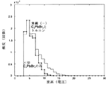
実施例1のガラス製セルに、製造例1で得た結晶を0.8g封入し、トルエン等の溶媒で満たさずに、そのまま使用して、実施例1と同様の測定を行った。
その波高分布を図4に示す。トルエンを加えたほう(実施例1)が、波高分布が上に伸びており、発光量が大きく、シンチレータとしての性能が向上していることが分かる。
また、時間スペクトルを図5に示す。トルエンを加えたほうが時間分解能が向上していることが分かる。
Comparative Example 1
In the glass cell of Example 1, 0.8 g of the crystal obtained in Production Example 1 was encapsulated and used as it was without being filled with a solvent such as toluene, and the same measurement as in Example 1 was performed.
The wave height distribution is shown in FIG. It can be seen that when toluene is added (Example 1), the wave height distribution extends upward, the light emission amount is large, and the performance as a scintillator is improved.
The time spectrum is shown in FIG. It can be seen that the time resolution is improved by adding toluene.
以上のように、本発明のペロブスカイト型化合物をガラスセルに封入し、有機溶媒(トルエン)で満たしたシンチレーターを用いたガンマ線測定を行えば、十分高速の時間分解能を得ることが可能である。同時に、発光波長が可視光で、任意形状をとれ、原子番号の大きい物質(鉛)を含み、製造設備が大規模でないため、PETでの使用に適する。 As described above, sufficiently high time resolution can be obtained by gamma-ray measurement using a scintillator filled with the perovskite type compound of the present invention in a glass cell and filled with an organic solvent (toluene). At the same time, the emission wavelength is visible light, it can take any shape, contains a substance with a large atomic number (lead), and the manufacturing equipment is not large, so it is suitable for use in PET.
Claims (2)
R1−NR2 3)2MX4
(式中、R1は複素環を含んでもよくハロゲン原子で置換されていてもよい一価炭化水素基、R2は、水素又は炭素数2以下のアルキル基、MはIVa族金属、Eu、Cd、Cu、Fe、Mn又はPd、Xはハロゲン原子を表す。)で表され、該有機溶媒に対するペロブスカイト型有機無機ハイブリッド化合物の量が0.03〜3.0g/ccである放射線検出用シンチレーター。 A scintillator for radiation detection in which a perovskite-type organic-inorganic hybrid compound and an organic solvent are enclosed in a glass cell, wherein the perovskite-type organic-inorganic hybrid compound has the general formula R 1 —NR 2 3 ) 2 MX 4
(In the formula, R 1 may contain a heterocyclic ring and may be substituted with a halogen atom, R 2 is hydrogen or an alkyl group having 2 or less carbon atoms, M is a group IVa metal, Eu, Cd, Cu, Fe, Mn or Pd, X represents a halogen atom.) The amount of the perovskite organic-inorganic hybrid compound relative to the organic solvent is 0.03 to 3.0 g / cc. .
Priority Applications (1)
| Application Number | Priority Date | Filing Date | Title |
|---|---|---|---|
| JP2004364250A JP2006170827A (en) | 2004-12-16 | 2004-12-16 | Scintillator for detecting radiation |
Applications Claiming Priority (1)
| Application Number | Priority Date | Filing Date | Title |
|---|---|---|---|
| JP2004364250A JP2006170827A (en) | 2004-12-16 | 2004-12-16 | Scintillator for detecting radiation |
Publications (2)
| Publication Number | Publication Date |
|---|---|
| JP2006170827A true JP2006170827A (en) | 2006-06-29 |
| JP2006170827A5 JP2006170827A5 (en) | 2007-03-08 |
Family
ID=36671745
Family Applications (1)
| Application Number | Title | Priority Date | Filing Date |
|---|---|---|---|
| JP2004364250A Pending JP2006170827A (en) | 2004-12-16 | 2004-12-16 | Scintillator for detecting radiation |
Country Status (1)
| Country | Link |
|---|---|
| JP (1) | JP2006170827A (en) |
Cited By (7)
| Publication number | Priority date | Publication date | Assignee | Title |
|---|---|---|---|---|
| CN104388089A (en) * | 2014-11-04 | 2015-03-04 | 北京理工大学 | High-fluorescence-quantum-yield hybridized perovskite quantum dot material and preparation method thereof |
| JP2018535537A (en) * | 2015-09-17 | 2018-11-29 | コーニンクレッカ フィリップス エヌ ヴェKoninklijke Philips N.V. | Radiation detector and manufacturing method of radiation detector |
| CN111989595A (en) * | 2018-04-19 | 2020-11-24 | 新加坡国立大学 | Perovskite-based nano-scintillators |
| CN112684492A (en) * | 2020-12-23 | 2021-04-20 | 华南理工大学 | Halogenated perovskite quantum dot composite material for neutron detection and preparation method thereof |
| CN113219517A (en) * | 2021-05-08 | 2021-08-06 | 西北核技术研究所 | High-precision fusion neutron energy spectrum measuring device and method |
| CN113219518A (en) * | 2021-05-08 | 2021-08-06 | 西北核技术研究所 | Radiation detection device and detection method based on perovskite scintillator |
| US11733404B2 (en) | 2016-07-28 | 2023-08-22 | Nanyang Technological University | Apparatus for radiation detection |
-
2004
- 2004-12-16 JP JP2004364250A patent/JP2006170827A/en active Pending
Cited By (8)
| Publication number | Priority date | Publication date | Assignee | Title |
|---|---|---|---|---|
| CN104388089A (en) * | 2014-11-04 | 2015-03-04 | 北京理工大学 | High-fluorescence-quantum-yield hybridized perovskite quantum dot material and preparation method thereof |
| JP2018535537A (en) * | 2015-09-17 | 2018-11-29 | コーニンクレッカ フィリップス エヌ ヴェKoninklijke Philips N.V. | Radiation detector and manufacturing method of radiation detector |
| US11733404B2 (en) | 2016-07-28 | 2023-08-22 | Nanyang Technological University | Apparatus for radiation detection |
| CN111989595A (en) * | 2018-04-19 | 2020-11-24 | 新加坡国立大学 | Perovskite-based nano-scintillators |
| CN111989595B (en) * | 2018-04-19 | 2024-03-15 | 新加坡国立大学 | Perovskite-based nano scintillator |
| CN112684492A (en) * | 2020-12-23 | 2021-04-20 | 华南理工大学 | Halogenated perovskite quantum dot composite material for neutron detection and preparation method thereof |
| CN113219517A (en) * | 2021-05-08 | 2021-08-06 | 西北核技术研究所 | High-precision fusion neutron energy spectrum measuring device and method |
| CN113219518A (en) * | 2021-05-08 | 2021-08-06 | 西北核技术研究所 | Radiation detection device and detection method based on perovskite scintillator |
Similar Documents
| Publication | Publication Date | Title |
|---|---|---|
| Yuan | Air-stable bulk halide single-crystal scintillator Cs3Cu2I5 by melt growth: intrinsic and Tl doped with high light yield | |
| Cheng et al. | Zero‐Dimensional Cs3Cu2I5 Perovskite Single Crystal as Sensitive X‐Ray and γ‐Ray Scintillator | |
| Yu et al. | Two-dimensional halide perovskite as β-ray scintillator for nuclear radiation monitoring | |
| Wang et al. | Emergence of uranium as a distinct metal center for building intrinsic X‐ray scintillators | |
| Dujardin et al. | Needs, trends, and advances in inorganic scintillators | |
| JP3714918B2 (en) | Radiation detector | |
| Fraboni et al. | Ionizing radiation detectors based on solution‐grown organic single crystals | |
| JP5984946B2 (en) | Rare earth metal halide scintillator having reduced hygroscopicity and method for producing the same | |
| US9121952B2 (en) | Scintillators and applications thereof | |
| CN113325462B (en) | Preparation method of perovskite nanocrystal-based gamma ray scintillation conversion screen | |
| CN114196396B (en) | Two-dimensional organic-inorganic hybrid perovskite scintillator capable of detecting gamma rays and fast neutrons simultaneously and preparation thereof | |
| Yao et al. | High‐Quality Cs3Cu2I5 Single‐Crystal is a Fast‐Decaying Scintillator | |
| Koshimizu | Recent progress of organic scintillators | |
| JP3779604B2 (en) | Radiation detector | |
| JP3779596B2 (en) | Positron emission tomography equipment | |
| Carturan et al. | Thermal neutron detection by entrapping 6LiF nanocrystals in siloxane scintillators | |
| JP2006170827A (en) | Scintillator for detecting radiation | |
| Fujimoto et al. | Copper iodide semiconductor: a non-hygroscopic, bright red-emitting scintillator for X-ray and gamma-ray detection | |
| US9417343B1 (en) | Neutron detector and fabrication method thereof | |
| JP2023551754A (en) | Scintillator materials containing halogenated perovskites | |
| Wen et al. | Synthesis and Characterization of All‐Inorganic Perovskite CsEuBr3 Single‐Crystal Scintillator | |
| Cova et al. | Scintillation Properties of CsPbBr3 Nanocrystals Prepared by Ligand-Assisted Reprecipitation and Dual Effect of Polyacrylate Encapsulation toward Scalable Ultrafast Radiation Detectors | |
| Bhattacharya et al. | Bridgman-grown CsI: Tl crystals codoped to suppress afterglow for high-throughput cargo inspection | |
| Liu | High-Z Nanoparticle/Polymer Nanocomposites for Gamma-Ray Scintillation Detectors | |
| Li et al. | Facile Preparation of CsPbBr3 Nanocrystals/Ethylene Vinyl Acetate Copolymer Composite Films with Long Term Stability and Flexibility for X‐ray Imaging |
Legal Events
| Date | Code | Title | Description |
|---|---|---|---|
| A521 | Written amendment |
Free format text: JAPANESE INTERMEDIATE CODE: A523 Effective date: 20070122 |
|
| A621 | Written request for application examination |
Free format text: JAPANESE INTERMEDIATE CODE: A621 Effective date: 20070122 |
|
| A977 | Report on retrieval |
Free format text: JAPANESE INTERMEDIATE CODE: A971007 Effective date: 20090622 |
|
| A131 | Notification of reasons for refusal |
Free format text: JAPANESE INTERMEDIATE CODE: A131 Effective date: 20090706 |
|
| A02 | Decision of refusal |
Free format text: JAPANESE INTERMEDIATE CODE: A02 Effective date: 20091030 |