JP2006132711A - Method of manufacturing hub unit for supporting wheel - Google Patents
Method of manufacturing hub unit for supporting wheel Download PDFInfo
- Publication number
- JP2006132711A JP2006132711A JP2004323928A JP2004323928A JP2006132711A JP 2006132711 A JP2006132711 A JP 2006132711A JP 2004323928 A JP2004323928 A JP 2004323928A JP 2004323928 A JP2004323928 A JP 2004323928A JP 2006132711 A JP2006132711 A JP 2006132711A
- Authority
- JP
- Japan
- Prior art keywords
- load
- collision
- caulking
- mold
- hub
- Prior art date
- Legal status (The legal status is an assumption and is not a legal conclusion. Google has not performed a legal analysis and makes no representation as to the accuracy of the status listed.)
- Withdrawn
Links
Images


Classifications
-
- F—MECHANICAL ENGINEERING; LIGHTING; HEATING; WEAPONS; BLASTING
- F16—ENGINEERING ELEMENTS AND UNITS; GENERAL MEASURES FOR PRODUCING AND MAINTAINING EFFECTIVE FUNCTIONING OF MACHINES OR INSTALLATIONS; THERMAL INSULATION IN GENERAL
- F16C—SHAFTS; FLEXIBLE SHAFTS; ELEMENTS OR CRANKSHAFT MECHANISMS; ROTARY BODIES OTHER THAN GEARING ELEMENTS; BEARINGS
- F16C35/00—Rigid support of bearing units; Housings, e.g. caps, covers
- F16C35/04—Rigid support of bearing units; Housings, e.g. caps, covers in the case of ball or roller bearings
- F16C35/06—Mounting or dismounting of ball or roller bearings; Fixing them onto shaft or in housing
- F16C35/063—Fixing them on the shaft
-
- B—PERFORMING OPERATIONS; TRANSPORTING
- B21—MECHANICAL METAL-WORKING WITHOUT ESSENTIALLY REMOVING MATERIAL; PUNCHING METAL
- B21J—FORGING; HAMMERING; PRESSING METAL; RIVETING; FORGE FURNACES
- B21J9/00—Forging presses
- B21J9/02—Special design or construction
- B21J9/025—Special design or construction with rolling or wobbling dies
-
- B—PERFORMING OPERATIONS; TRANSPORTING
- B21—MECHANICAL METAL-WORKING WITHOUT ESSENTIALLY REMOVING MATERIAL; PUNCHING METAL
- B21K—MAKING FORGED OR PRESSED METAL PRODUCTS, e.g. HORSE-SHOES, RIVETS, BOLTS OR WHEELS
- B21K25/00—Uniting components to form integral members, e.g. turbine wheels and shafts, caulks with inserts, with or without shaping of the components
-
- F—MECHANICAL ENGINEERING; LIGHTING; HEATING; WEAPONS; BLASTING
- F16—ENGINEERING ELEMENTS AND UNITS; GENERAL MEASURES FOR PRODUCING AND MAINTAINING EFFECTIVE FUNCTIONING OF MACHINES OR INSTALLATIONS; THERMAL INSULATION IN GENERAL
- F16C—SHAFTS; FLEXIBLE SHAFTS; ELEMENTS OR CRANKSHAFT MECHANISMS; ROTARY BODIES OTHER THAN GEARING ELEMENTS; BEARINGS
- F16C19/00—Bearings with rolling contact, for exclusively rotary movement
- F16C19/22—Bearings with rolling contact, for exclusively rotary movement with bearing rollers essentially of the same size in one or more circular rows, e.g. needle bearings
- F16C19/34—Bearings with rolling contact, for exclusively rotary movement with bearing rollers essentially of the same size in one or more circular rows, e.g. needle bearings for both radial and axial load
- F16C19/38—Bearings with rolling contact, for exclusively rotary movement with bearing rollers essentially of the same size in one or more circular rows, e.g. needle bearings for both radial and axial load with two or more rows of rollers
- F16C19/383—Bearings with rolling contact, for exclusively rotary movement with bearing rollers essentially of the same size in one or more circular rows, e.g. needle bearings for both radial and axial load with two or more rows of rollers with tapered rollers, i.e. rollers having essentially the shape of a truncated cone
- F16C19/385—Bearings with rolling contact, for exclusively rotary movement with bearing rollers essentially of the same size in one or more circular rows, e.g. needle bearings for both radial and axial load with two or more rows of rollers with tapered rollers, i.e. rollers having essentially the shape of a truncated cone with two rows, i.e. double-row tapered roller bearings
- F16C19/386—Bearings with rolling contact, for exclusively rotary movement with bearing rollers essentially of the same size in one or more circular rows, e.g. needle bearings for both radial and axial load with two or more rows of rollers with tapered rollers, i.e. rollers having essentially the shape of a truncated cone with two rows, i.e. double-row tapered roller bearings in O-arrangement
-
- F—MECHANICAL ENGINEERING; LIGHTING; HEATING; WEAPONS; BLASTING
- F16—ENGINEERING ELEMENTS AND UNITS; GENERAL MEASURES FOR PRODUCING AND MAINTAINING EFFECTIVE FUNCTIONING OF MACHINES OR INSTALLATIONS; THERMAL INSULATION IN GENERAL
- F16C—SHAFTS; FLEXIBLE SHAFTS; ELEMENTS OR CRANKSHAFT MECHANISMS; ROTARY BODIES OTHER THAN GEARING ELEMENTS; BEARINGS
- F16C2326/00—Articles relating to transporting
- F16C2326/01—Parts of vehicles in general
- F16C2326/02—Wheel hubs or castors
Abstract
Description
本発明は、自動車の車輪を懸架装置に対して回転自在に支持する車輪支持用ハブユニットに於いて、加締めを行う車輪支持用ハブユニットの製造方法に関する。 The present invention relates to a method for manufacturing a wheel support hub unit that performs caulking in a wheel support hub unit that rotatably supports a vehicle wheel with respect to a suspension device.
自動車の車輪を懸架装置に対して回転自在に支持するため、特許文献1に開示してあるように、車輪支持用転がり軸受ユニットを使用している。 In order to rotatably support the wheel of an automobile with respect to a suspension device, as disclosed in Patent Document 1, a wheel bearing rolling bearing unit is used.
図5は、車輪支持用転がり軸受ユニットの断面図である。外輪1の内径側に、転動体である複数の円錐ころ3,3を介して、ハブ2が回転自在に支持してある。外輪1の内周面には、1対の外輪軌道4,4が形成してあると共に、外周面には、懸架装置に支持固定するための取付部5が設けてある。
FIG. 5 is a cross-sectional view of the wheel-supporting rolling bearing unit. A
ハブ2は、軸部材であるハブ本体6と、一対の内輪7,7とを組み合わせてなる。ハブ本体6は、車輪を支持するためのフランジ8を外周面の外端(図5の左方)部に形成している。
The
ハブ本体6には、小径の段部10が形成してある。この段部10には、夫々内輪軌道9a,9bを有する一対の内輪7a,7bが圧入・嵌合してある。
The
一方の内輪7bは、ハブ本体6の内端部に設けた加締め部11により、段部10に向けて押圧してある。
One
この加締め部11は、ハブ本体6の内端部であって、段部10に圧入・外嵌した内輪7bの内端面よりも軸方向に突出する部分の中空突出部13を、揺動プレス装置により、径方向外方に向けて、ローリング加締め加工して、形成してある。
The
このようなローリング加締め加工では、ワークには金型を介して荷重(力)が加わる。加工開始直後、金型とワークが衝突すると、金型は、準静的または静的な荷重(Fstatic=P0)に加えて、慣性力による荷重(ΔFinertia)を受ける。慣性力による荷重は次式で表せる。
ΔFinertia=M・V/Δt
M:質量(機械本体に対して動く側、本明細書ではワーク側の昇降する部分)
V:相対速度(本明細書ではワーク側の装置が金型に近づく速さ)
Δt:相対速度がVからゼロになるまでの時間
本明細書において準静的または静的な荷重(Fstatic=P0)を「設定荷重」と呼ぶことにし、設定荷重に慣性力を加えた荷重(Fstatic+ΔFinertia=P1)を「衝突荷重」と呼ぶことにする。
In such rolling caulking, a load (force) is applied to the work through a mold. When the mold collides with the workpiece immediately after the start of machining, the mold receives a load (ΔFinertia) due to inertial force in addition to a quasi-static or static load (Fstatic = P0). The load due to inertial force can be expressed by the following equation.
ΔFinertia = MVV / Δt
M: Mass (the moving side with respect to the machine body, in this specification, the part that moves up and down on the workpiece side)
V: Relative speed (in this specification, the speed at which the device on the workpiece side approaches the mold)
Δt: Time until the relative speed becomes zero from V In this specification, a quasi-static or static load (Fstatic = P0) is referred to as a “set load”, and a load obtained by adding an inertial force to the set load ( Fstatic + ΔFinertia = P1) will be referred to as “impact load”.
従来、ローリング加締め加工においては、「設定荷重」についでは管理していたが、「衝突荷重」については管理していなかった。すなわち、慣性力による荷重については、考慮されていなかった。
ところが、同じ「設定荷重」でも、あるレベルより「衝突荷重」が高いと、金型表面は、ワークと衝突する個所が損傷して、金型の寿命が短くなるという問題が発生した。 However, even if the “set load” is the same, if the “collision load” is higher than a certain level, there is a problem in that the mold surface is damaged at the location where it collides with the workpiece, and the life of the mold is shortened.
本発明は、上述したような事情に鑑みてなされたものであって、「衝突荷重」と「設定荷重」の条件を設定することによって、衝突による金型の損傷を減少して、金型の寿命を安定することができる、車輪支持用ハブユニットの製造方法を提供することを目的とする。 The present invention has been made in view of the above-described circumstances, and by setting the conditions of “impact load” and “set load”, damage to the mold due to the collision is reduced, and the mold It is an object of the present invention to provide a method for manufacturing a wheel-supporting hub unit that can stabilize the service life.
上記の目的を達成するため、本発明の請求項1に係る車輪支持用ハブユニットの製造方法は、ハブ本体の内端部であり、ハブ本体の段部に外嵌した内輪の内端面よりも軸方向内方に突出する中空突出部を、径方向外方に向けて加締め加工する車輪支持用ハブユニットの製造方法に於いて、
前記加締め加工時、「衝突荷重(P1)」/「設定荷重(P0)」の比(P1/P0)は、1〜1.3に設定してあることを特徴とする。
In order to achieve the above object, a method for manufacturing a hub unit for supporting a wheel according to claim 1 of the present invention is an inner end portion of a hub main body, which is more than an inner end surface of an inner ring fitted on a step portion of the hub main body. In a method for manufacturing a wheel-supporting hub unit, in which a hollow projecting portion projecting inward in the axial direction is crimped toward the radially outward direction,
During the caulking process, the ratio (P1 / P0) of “collision load (P1)” / “set load (P0)” is set to 1 to 1.3.
本発明によれば、加締め加工時、「衝突荷重(P1)」/「設定荷重(P0)」の比(P1/P0)は、1〜1.3に設定してあることから、衝突による金型の損傷を減少して、金型の寿命を安定することができる。 According to the present invention, at the time of caulking, the ratio (P1 / P0) of “collision load (P1)” / “set load (P0)” is set to 1 to 1.3. The damage of the mold can be reduced and the life of the mold can be stabilized.
以下、本発明の実施の形態に係る車輪支持用ハブユニットの製造方法を図面を参照しつつ説明する。 Hereinafter, a manufacturing method of a wheel supporting hub unit according to an embodiment of the present invention will be described with reference to the drawings.
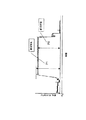
図1は、ローリング加締め加工時に於ける、時間と荷重との関係を示すグラフである。 FIG. 1 is a graph showing the relationship between time and load during rolling caulking.
ハブのローリング加締め加工において、「衝突荷重(P1)」と「設定荷重(P0)」の比(P1/P0)と、金型寿命の関係を調べた。 In the rolling caulking process of the hub, the relationship between the ratio (P1 / P0) between the “impact load (P1)” and the “set load (P0)” and the mold life was examined.
「衝突荷重(P1)」と「設定荷重(P0)」の比(P1/P0)は、金型形状やワーク加締め部形状を変えることで、いろいろな値を準備した。 Various values were prepared for the ratio (P1 / P0) of the “collision load (P1)” and the “set load (P0)” by changing the shape of the mold and the shape of the work caulking part.

実験結果を表1に示す。表1の左側は、「衝突荷重(P1)」と「設定荷重(P0)」の比(P1/P0)を、上から小さい順に並べている。 The experimental results are shown in Table 1. On the left side of Table 1, the ratio (P1 / P0) of “collision load (P1)” and “set load (P0)” is arranged in ascending order from the top.
表1右側は、ワークと金型の衝突によって、金型表面に損傷が発生したかどうかの評価結果である。金型寿命の評価は、ある所定個数加締めた後に、金型表面の損傷が肉眼で観察できない場合は○、損傷が観察できる場合は×、としている。 The right side of Table 1 is an evaluation result of whether or not the mold surface is damaged due to the collision between the workpiece and the mold. The evaluation of the mold life is ◯ when damage to the mold surface cannot be observed with the naked eye after caulking a predetermined number, and x when damage can be observed.
表1の通り、(P1/P0)が1.37以上の場合、ワークと金型の衝突による損傷が金型表面に発生したのを確認した。 As shown in Table 1, when (P1 / P0) was 1.37 or more, it was confirmed that damage due to collision between the workpiece and the mold occurred on the mold surface.
(Pl/P0)が1.29以下の場合、衝突を原因とする損傷が金型表面に観察できなかった。 When (Pl / P0) was 1.29 or less, damage due to collision could not be observed on the mold surface.
実際の生産では、小数点以下第2位を四捨五入して、(P1/P0)を1.3以下という条件で管理している。 In actual production, the second decimal place is rounded off, and (P1 / P0) is managed under the condition of 1.3 or less.
以上から、本実施の形態によれば、ローリング加締め加工時、「衝突荷重(P1)」/「設定荷重(P0)」の比(P1/P0)は、1〜1.3に設定してあることから、衝突による金型の損傷を減少して、金型の寿命を安定することができる。 From the above, according to the present embodiment, during rolling caulking, the ratio (P1 / P0) of “collision load (P1)” / “set load (P0)” is set to 1 to 1.3. As a result, damage to the mold due to the collision can be reduced, and the life of the mold can be stabilized.
なお、図1に於いて、「設定荷重(P0)」の値は、金型(後述する押型15)の揺動角によって変化する。
In FIG. 1, the value of “set load (P0)” varies depending on the swing angle of a mold (a
例えば、揺動角が5度の時、「設定荷重(P0)」の値は、7〜13であり、揺動角が2度の時、「設定荷重(P0)」の値は、13〜25である。 For example, when the swing angle is 5 degrees, the value of “set load (P0)” is 7 to 13, and when the swing angle is 2 degrees, the value of “set load (P0)” is 13 to 13. 25.
ここで、(P1/P0)を小さくするには、「衝突荷重(P1)」のうち、慣性力による荷重を減らすことが重要である。慣性力による荷重はΔFinertia=M・V/Δtで表されるので、Δtを大きくする、Vを小さくする、Mを小さくすることが慣性力による荷重を減らす方法になる。以下、「衝突荷重(P1)」を減らす方法を記す。 Here, in order to reduce (P1 / P0), it is important to reduce the load caused by the inertia force among the “collision load (P1)”. Since the load due to inertial force is expressed by ΔFinertia = M · V / Δt, increasing Δt, decreasing V, and decreasing M are methods for reducing the load due to inertial force. Hereinafter, a method of reducing the “collision load (P1)” will be described.
I − Δtを大きくする(ワークと金型の衝突を緩和させること)
(1) 金型のR形状の部分でワークと衝突するようにする。
(2) 金型表面を鏡面(Ra0.2μmまたはRy0.8μm以下、かつ加工目が肉眼で見えないこと)にして、ワークが変形しやすいようにする。
(3) ワークの内径側をテーパーにし、ワーク先端が変形しやすいようにする。
(4) 内輪端面からワーク先端の突き出る長さ(h)と厚さ(t)の比h/tを1.6以上にする(図3参照)。
(5) ワーク先端の硬さをHRC25以下にする。
(6) ワークをバネで浮かせる。
II − Vを小さくする
(7) 金型とワークの衝突する速度を小さくする。
III − Mを小さくする
(8) 昇降する部分の質量を小さくする。
以下にその詳細を示す。
Increase I-Δt (to reduce collision between workpiece and mold)
(1) Collide with the workpiece at the R-shaped part of the mold.
(2) The surface of the mold is mirror-finished (Ra 0.2 μm or Ry 0.8 μm or less and the processed eyes cannot be seen with the naked eye) so that the workpiece is easily deformed.
(3) Tap the inner diameter of the workpiece so that the tip of the workpiece is easily deformed.
(4) The ratio h / t of the length (h) and thickness (t) at which the tip of the workpiece protrudes from the inner ring end face is set to 1.6 or more (see FIG. 3).
(5) The hardness of the workpiece tip is made HRC25 or less.
(6) Lift the work with a spring.
II-V is reduced (7) The speed at which the mold collides with the work is reduced.
III-M Reduce (8) Reduce the mass of the part that moves up and down.
The details are shown below.
(第1実施の形態)
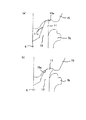
図2は、本発明の第1実施の形態に係り、(a)は、ローリング加締め加工時に於いて、「衝突荷重(P1)」の発生時を示し、(b)は、「衝突荷重(P1)」の終了時を示す。ここで、ワーク内径をテーパーにし、また金型表面をR形状にし、ワークは金型のR形状部分と衝突する。
(First embodiment)
2A and 2B relate to the first embodiment of the present invention. FIG. 2A shows the occurrence of “collision load (P1)” during rolling caulking, and FIG. P1) ”ends. Here, the work inner diameter is tapered and the surface of the mold is formed in an R shape, and the work collides with the R-shaped portion of the mold.
図2(a)に於いて、「衝突荷重(P1)」の発生時、ワーク(後述する加締め部11)と、金型(後述する押型15)の衝突をワーク(加締め部11)の変形で緩和させる(Δtを大きくする)ため、金型(押型15)のR形状部分(15a)でワーク(加締め部11)と衝突するようにしてある。
In FIG. 2A, when the “collision load (P1)” is generated, the collision between the workpiece (clamping
また、図2(a)に於いて、「衝突荷重(P1)」の発生時、ワーク(後述する加締め部11)と、金型(後述する押型15)の衝突をワーク(加締め部11)の変形で緩和させる(Δtを大きくする)ため、ワーク(加締め部11)の内径側(11a)をテーパーにし、ワーク(加締め部11)先端が変形しやすいようにしてある。
Further, in FIG. 2A, when the “collision load (P1)” is generated, the collision between the workpiece (clamping
図2(b)に於いて、「衝突荷重(P1)」の終了時、ワーク(後述する加締め部11)と、金型(後述する押型15)の衝突をワーク(加締め部11)の変形で緩和させる(Δtを大きくする)ため、金型(押型15)のR形状部分(15a)表面の面粗度を良く、できれば鏡面にして、ワーク(加締め部11)が変形しやすいようにしてある。
2B, at the end of the “collision load (P1)”, the collision between the workpiece (clamping
(第2実施の形態)
図3は、本発明の第2実施の形態に係り、(a)は、ローリング加締め加工時に於いて、「衝突荷重(P1)」の発生時を示し、(b)は、「衝突荷重(P1)」の終了時を示す。
(Second Embodiment)
FIG. 3 relates to a second embodiment of the present invention, wherein (a) shows the occurrence of “collision load (P1)” during rolling caulking, and (b) shows “collision load ( P1) ”ends.
図3(a)に於いて、「衝突荷重(P1)の発生時、ワーク(加締め部11)と金型(押型15)の衝突をワークの突き出た部分の形状をh/t≧1.6とすることで、ワーク(加締め部11)先端が変形しやすいようにしてある。 In FIG. 3A, “when the collision load (P1) is generated, the shape of the part where the workpiece protrudes due to the collision between the workpiece (clamping portion 11) and the die (pressing die 15) is h / t ≧ 1. By setting it to 6, the tip of the workpiece (caulking portion 11) is easily deformed.
また、図3(a)に於いて、ワーク(後述する加締め部11)と、金型(後述する押型15)の衝突時に発生する面圧を減ずるため、ハブ本体6の中空突出部13(即ち、加締め部11)の内径側の先端には、R面取り部11bが形成してある。
Further, in FIG. 3A, in order to reduce the surface pressure generated when the workpiece (clamping
なお、本実施の形態では、加締め部11の内径側(11a)も、円筒形状に形成してある。
In the present embodiment, the inner diameter side (11a) of the
図3(b)は、ワーク(後述する加締め部11)と、金型(後述する押型15)の衝突が終了し、加工が始まった状態を示している。
FIG. 3B shows a state where the collision between the workpiece (clamping
なお、各実施例で、ワーク材料はS50〜55Cの材料を使用するのが望ましい。硬さはHRC15〜27である。この硬さを熱間鍛造後、コントロールクーリングして、HRC25以下にすることで、塑性変形しやすくし、ワーク(加締め部11)先端が変形しやすいようにしてある。 In each embodiment, it is desirable to use a material of S50 to 55C as the work material. Hardness is HRC15-27. This hardness is controlled for cooling after hot forging to HRC25 or less, so that plastic deformation is facilitated and the tip of the workpiece (caulking portion 11) is easily deformed.
(第3実施の形態)
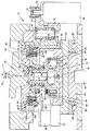
図4は、本発明の第3実施の形態に係り、製造装置である揺動プレス装置の断面図である。
(Third embodiment)
FIG. 4 is a sectional view of an oscillating press apparatus as a manufacturing apparatus according to the third embodiment of the present invention.
なお、以下に、ローリング加締めを行う揺動プレス装置を説明するが、これは、一例にすぎず、本発明は、この揺動プレス装置に限定されないことは、勿論である。 In addition, although the rocking press apparatus which performs rolling caulking is demonstrated below, this is only an example and it cannot be overemphasized that this invention is not limited to this rocking press apparatus.
揺動プレス装置14は、昇降台23を有する。この昇降台23は、油圧シリンダ等の押圧装置(図示略)の出力ロッド24の上端部に固定されており、加締め部11の加工時に、押圧装置により上方に押し上げられる。
The
この様な昇降台23の上面には、図4の表裏方向に水平移動するスライドテーブル25を設け、更にこのスライドテーブル25の上面に、ホルダ26を介して支持ブロック27を載置している。
A slide table 25 that horizontally moves in the front and back direction of FIG. 4 is provided on the upper surface of such a
尚、昇降台23の上面で1対のスライダ28、28の間部分にバックアッププレート29を固定し、このバックアッププレート29の上面を、スライドテーブル25の下面に摺接若しくは近接対向させている。
A
支持ブロック27は、ハブ2を構成するハブ本体6の外端(図4で下方)部を支える為のもので、上面中央部に支持円筒部30を固設している。
The
この支持円筒部30は、ホイールの内周縁部を外嵌する為に、ハブ本体6の外端面に設けた位置決め筒部31をほぼがたつきなく内嵌自在な内径と、ハブ本体6の外周面に設けたフランジ8の外側面にほぼ密接自在な上端面形状とを有する。
The supporting
支持ブロック27の上方には、ハブ本体6の内端部に形成した中空突出部13を塑性変形する為の加圧部材である押型15を設けている。この押型15は、例えば、揺動角5度であって、図示しない支持ヘッドの下端部に支持されている。
Above the
この押型15の中心軸αは、ハブ本体6の中心軸βに対し、小さな角度θだけ傾斜している。ハブ本体6の内端部に加締め部11を加工する際に押型15は、その中心軸αをハブ本体6の中心軸βの回りで振れ回り運動させる。
The center axis α of the die 15 is inclined by a small angle θ with respect to the center axis β of the
そして、この状態で昇降台23を上方に押し上げる事により、中空突出部13の上端縁を押型15の下面に押し付ける。そして、この押型15からこの中空突出部13の円周方向の一部に、軸方向に関して外方(図4の下方)に、径方向に関して外方に、それぞれ向いた荷重を加える。この様にして中空突出部13に荷重を加える位置は、中心軸αの振れ回り運動に伴って、この中空突出部13の円周方向に関して連続的に変化する。
In this state, the
尚、押型15は、この中空突出部13を加圧するのに伴う反力により亀裂等の損傷が発生しない様に剛性を高くすべく、加締め部11を形成する為の先端部から離れるに従って(上方程)外径が大きくなる方向に傾斜したテーパ形状としている。
In addition, as the
押型15の周囲に、円輪状の支持枠32(内輪クランプ)を設けている。この支持枠32の中央部には、この押型15の振れ回り運動を許容すべく、上方に向かう程内径が大きくなる方向に傾斜した内周面を有する、摺鉢状の通孔33を設けている。
An annular support frame 32 (inner ring clamp) is provided around the
そして、支持枠32の下面でこの通孔33を囲む部分に、略短円筒状の押圧筒部34を形成している。この押圧筒部34は、押型15により中空突出部13を加締め部11に加工する際に、ハブ本体6が径方向に振れ動くのを規制する役目を有する。
Then, a
この為に押圧筒部34の下端部内周面は、ハブ本体6の内端部に外嵌した内輪7の外周面に、0.1〜0.5m程度の微小な大きさの隙間を介して対向させている。それにより、内輪の外周面に傷をつけにくくなる。
For this purpose, the inner peripheral surface of the lower end portion of the
尚、支持枠32は、図示しないフレームの一部に、やはり図示しない3本の油圧アクチュエータにより、若干の昇降自在に支持している。
The
支持枠32の下面外周寄り部分に、上下1対の連結環35a、35bを介して、欠円筒状の保持筒36を、吊り下げ固定している。この保持筒6は、昇降台23が上昇し、支持枠32が下降した状態で、ホルダ26に外嵌される。
A holding
連結環35bの内径側に駆動環37を、転がり軸受38により、回転自在に支持している。この転がり軸受38は、旋回輪の如く、ラジアル荷重及びスラスト荷重を支承自在な構造を有する。駆動環37は、押型15により加締め部11を加工する際に、外輪1を所定速度で回転させる為のもので、この外輪1の外周面に設けた取付部5に、円輪伏の駆動治具39(割出しプレート)を外嵌した状態で、モータ40により、回転駆動される。
A
駆動治具39は、駆動環37に駆動環37に対する若干の昇降を自在に、且つ、駆動環37と同期した回転を自在に組み合わせている。この為に本例の場合には、この駆動環37の円周方向複数個所(例えば4〜6個所)に、それぞれがこの駆動環37の中心軸と平行な支持孔41、41を形成している。
The
駆動治具39の外周面上端部に固定した取付フランジ42の一部で各支持孔41、41に整合する部分に、それぞれが駆動治具39の中心軸と平行に配置されたガイドピン43、43の基端部を結合固定している。そして、これら各ガイドピン43、43を各支持孔41、41に挿通し、更に、これら各ガイドピン43、43の下端部に形成した鍔部の上面と取付フランジ42の下面との間に、圧縮ばねを設けている。
Guide pins 43 arranged in parallel to the center axis of the
この構成により、駆動治具39は、下方に向かう弾力を付与された状態で、駆動環37に対し若干の昇降自在に、且つ、この駆動環37と同期した回転自在に支持されている。
With this configuration, the driving
この様な駆動治具39の下面内周寄り部分には、取付部5の外周縁と非円形嵌合する凹部44を形成している。
A concave portion 44 that is non-circularly fitted to the outer peripheral edge of the mounting
一方、駆動環37を回転駆動する為のモータ40は、保持筒36の一部外周面に、連結ブラケット47と保持ブラケット48とにより支持固定している。
On the other hand, the
従って、モータ40は、支持枠32と共に昇降する。この様なモータ40の出力軸49と駆動環37とは、歯車減速機構50により結合して、この駆動環37を所定方向に所定速度で回転駆動自在としている。
Therefore, the
歯車減速機構50を構成する為に、連結ブラケット47に中間軸51を、出力軸49及び駆動環37の中心軸と平行に配置した状態で、回転自在に支持している。この駆動環37の下面外周寄り部分に、減速大歯車52を固定している。
In order to configure the
そして、この減速大歯車52と、出力軸49の先端部(図示の場合上端部)に固定した減速小歯車53とを、中間軸51の上端部に固定した中間歯車54を介して噛合させている。
Then, the reduction
この構成により駆動環37を、出力軸49と同方向に、この出力軸49よりも低速で回転駆動自在としている。
With this configuration, the
更に、支持ブロック27の上方には、回転制限部材である押圧ロッド55を、外輪1の外周面に対する進退自在に設けている。この為に本例の場合には、ホルダ26の外周面で保持筒36の不連続部に対応する部分に、エアシリンダ等のアクチュエ一タ56(ブレーキマウント)を固定し、このアクチュエータ56により押圧ロッド55を、外輪1の径方向に変位自在としている。なお、符号57は、シリンダーマウントを示している。
Further, above the
また、押圧ロッド55の先端部に、硬質ゴム、合成樹脂、軟質金属等、外輪1を構成する金属材料(炭素鋼)よりも軟らかい材料を設置する事が、外輪1の外周面の損傷防止の面から好ましい。
In addition, it is possible to prevent damage to the outer peripheral surface of the outer ring 1 by installing a material softer than the metal material (carbon steel) constituting the outer ring 1 such as hard rubber, synthetic resin, or soft metal at the tip of the
また、ハブ本体6の下方と、支持ブロック27との間には、ガタつきなく且つ若干の揺動変位自在に支持する受治具61が設けてあり、受治具61は、外ネジ式ストッパーボルト62により、支持ブロック27の中央部に揺動自在に設けてある。この受治具61により、加締め加工時に、ハブ2にモーメントが作用せず、ハブ2に曲り変形等が生じることを防止することができる。
Further, a receiving
さらに、ハブ2のフランジ8の下方側を支持するように、フランジサポート63が設けてあり、このフランジサポート63と、支持ブロック27の外周部の受けガイド部66との間に、外ネジ式ストッパーボルト64とコイルスプリング65とが設けてある。また、支持ブロック27の外周部の受けガイド部66は極低頭六角穴付ボルト67により取付けてある。このような弾性支持構成により、治具(押型15)とワーク(加締め部11)が衝突する時の衝撃を吸収することができる。
Further, a flange support 63 is provided so as to support the lower side of the
次に、上述の様に構成する揺動プレス装置14を使用し、ハブ本体6の内端部に設けた中空突出部13を塑性変形させて加締め部11とする際の作用に就いて説明する
先ず、昇降台23を下降させ、且つ、スライドテーブル25を図4の表裏方向にずらせて押型15の下方から支持ブロック27を抜き出した状態で、この支持ブロック27の上面にハブ本体6を載置する。このハブ本体6の内端部には、予め内輪7を外嵌しておく。
Next, an explanation will be given of the operation when the hollow projecting
次いで、スライドテーブル25を押型15の下方に、ハブ本体6の中心軸と支持枠32の中心軸とが一致する状態まで入り込ませる。その後、この支持枠32を下降させ、押圧筒部34の下端部を内輪7に外嵌する。
Next, the slide table 25 is inserted below the
取付部5と凹部44とを嵌合させて、駆動治具39により外輪1を回転駆動自在とする事により、加締め部11を加工する為の準備作業が完了する。
By fitting the mounting
そこで、モータ40により外輪1を、例えば数百min−1程度で回転させると共に、昇降台23を上昇させつつ、押型15によりハブ本体6の内端部に形成した中空突出部13を塑性変形させる。
Accordingly, the outer ring 1 is rotated by, for example, about several hundred min −1 by the
そして、加締め部11を形成し、この加締め部11により内輪7の内端面を押圧する。この際、押型15は、その中心軸αを上記ハブ本体6の中心軸βの回りで振れ回り運動させる。
Then, a
中空突出部13は、この様に振れ回り運動する押型15の下面に、油圧シリンダ等の押圧装置の出力ロッド24の押し上げ力に基づいて、押し付けられる。この際、中空突出部13を設けたハブ本体6は回転しない為、この中空突出部13の円周方向の一部に、軸方向に関して外端側に、径方向に関して外方に、それぞれ向いた荷重が加えられ、且つ、この荷重を加えられる部分が、中空突出部13の円周方向に関して連続的に変化する。
The hollow protruding
この結果、この中空突出部13が、円周方向に関して連続的に、且つ、徐々に塑性変形して、加締め部11となる。この様に中空突出部13が加締め部11となるのに伴って、ハブ本体6及びこのハブ本体6を載置した昇降台23、並びに支持枠32、モータ40、歯車減速機構50等が少しずつ上昇する。
As a result, the hollow projecting
尚、加締め部11の加工に伴ってスライドテーブル25に加わるスラスト荷重は、バックアッププレート29を介して、出力ロッド24により支承する。従って、スライダ28に過大な力が作用する事はなく、このスライダ28の耐久性を十分に確保できる。
Note that the thrust load applied to the slide table 25 as the
特に、本実施の形態では、上述したように、ハブ2のフランジ8の下方側を支持するように、フランジサポート63が設けてあり、このフランジサポート63と、支持ブロック27の外周部の受けガイド部66との間に、外ネジ式ストッパーボルト64とコイルスプリング65とが設けてある。また、支持ブロック27の外周部の受けガイド部66は極低頭六角穴付ボルト67により取付けてある。このような弾性支持構成により、治具(押型15)とワーク(加締め部11)が衝突する時の衝撃を吸収することができる。
In particular, in the present embodiment, as described above, the flange support 63 is provided so as to support the lower side of the
また、昇降台23の上昇速度を衝突直前に減速する制御をすることによって、治具(押型15)とワーク(加締め部11)が衝突するときの衝撃を吸収することができる。
Further, by controlling to reduce the ascending speed of the
また、昇降台23を含む昇降する部分の質量を軽くすることによって、治具(押型15)とワーク(加締め部11)が衝突するときの衝撃を吸収することができる。
Moreover, by reducing the mass of the part to be moved up and down including the
なお、本願発明は、治具のみが揺動回転する加締め方法だけでなく、ワーク本体が回転し、加締め固定させる場合にも適用することができる。 The present invention can be applied not only to a caulking method in which only a jig swings and rotates, but also to a case where the work body is rotated and fixed by caulking.
なお、本発明は、上述した実施の形態に限定されず、種々変形可能である。 In addition, this invention is not limited to embodiment mentioned above, A various deformation | transformation is possible.
1 外輪
2 ハブ
3 円錐ころ
4 外輪軌道
5 取付部
6 ハブ本体
7a,7b 内輪
8 フランジ
9a,9b 内輪軌道
10 段部
11 加締め部
11a 加締め部11の内径側
11b R面取り部
13 中空突出部
14 揺動プレス装置
15 押型
15a R形状部分
23 昇降台
24 出力ロッド
25 スライドテーブル
26 ホルダ
27 支持ブロック
28 スライダ
29 バックアッププレート
30 支持円筒部
31 位置決め筒部
32 支持枠
33 通孔
34 押圧筒部
35a、35b 連結環
36 保持筒
37 駆動環
38 転がり軸受
39 駆動治具
40 モータ
41 支持孔
42 取付フランジ
43 ガイドピン
44 凹部
47 連結ブラケット
48 保持ブラケット
49 出力軸
50 歯車減速機構
51 中間軸
52 減速大歯車
53 減速小歯車
54 中間歯車
55 押圧ロッド
56 アクチュエータ
57 シリンダーマウント
61 受治具
62 外ネジ式ストッパーボルト
63 フランジサポート
64 外ネジ式ストッパーボルト
65 コイルスプリング
66 受けガイド部
67 極低頭六角穴付ボルト
DESCRIPTION OF SYMBOLS 1
Claims (1)
前記加締め加工時、「衝突荷重(P1)」/「設定荷重(P0)」の比(P1/P0)は、1〜1.3に設定してあることを特徴とする車輪支持用ハブユニットの製造方法。 For wheel support, which is the inner end of the hub body and caulks the hollow projecting part that protrudes inward in the axial direction from the inner end surface of the inner ring that is externally fitted to the stepped part of the hub body. In the manufacturing method of the hub unit,
The wheel support hub unit, wherein a ratio (P1 / P0) of “impact load (P1)” / “set load (P0)” is set to 1 to 1.3 during the caulking process. Manufacturing method.
Priority Applications (1)
| Application Number | Priority Date | Filing Date | Title |
|---|---|---|---|
| JP2004323928A JP2006132711A (en) | 2004-11-08 | 2004-11-08 | Method of manufacturing hub unit for supporting wheel |
Applications Claiming Priority (1)
| Application Number | Priority Date | Filing Date | Title |
|---|---|---|---|
| JP2004323928A JP2006132711A (en) | 2004-11-08 | 2004-11-08 | Method of manufacturing hub unit for supporting wheel |
Publications (2)
| Publication Number | Publication Date |
|---|---|
| JP2006132711A true JP2006132711A (en) | 2006-05-25 |
| JP2006132711A5 JP2006132711A5 (en) | 2007-10-04 |
Family
ID=36726428
Family Applications (1)
| Application Number | Title | Priority Date | Filing Date |
|---|---|---|---|
| JP2004323928A Withdrawn JP2006132711A (en) | 2004-11-08 | 2004-11-08 | Method of manufacturing hub unit for supporting wheel |
Country Status (1)
| Country | Link |
|---|---|
| JP (1) | JP2006132711A (en) |
Cited By (4)
| Publication number | Priority date | Publication date | Assignee | Title |
|---|---|---|---|---|
| JP2008190692A (en) * | 2007-02-07 | 2008-08-21 | Nsk Ltd | Method for manufacturing bearing device |
| WO2018179192A1 (en) * | 2017-03-29 | 2018-10-04 | 不二商事株式会社 | Inner race constraining device for vehicular hub bearing |
| WO2019097972A1 (en) * | 2017-11-20 | 2019-05-23 | 日本精工株式会社 | Rotary swaging device, method for manufacturing hub unit bearing, and method for manufacturing vehicle |
| CN112566803A (en) * | 2018-06-12 | 2021-03-26 | 日本发条株式会社 | Stabilizer and method for manufacturing the same |
-
2004
- 2004-11-08 JP JP2004323928A patent/JP2006132711A/en not_active Withdrawn
Cited By (14)
| Publication number | Priority date | Publication date | Assignee | Title |
|---|---|---|---|---|
| JP4552951B2 (en) * | 2007-02-07 | 2010-09-29 | 日本精工株式会社 | Manufacturing method of bearing device |
| JP2008190692A (en) * | 2007-02-07 | 2008-08-21 | Nsk Ltd | Method for manufacturing bearing device |
| US10914340B2 (en) | 2017-03-29 | 2021-02-09 | Fuji Shoji Co., Ltd. | Inner-ring restraint device of hub bearing for vehicle |
| WO2018179192A1 (en) * | 2017-03-29 | 2018-10-04 | 不二商事株式会社 | Inner race constraining device for vehicular hub bearing |
| CN110461492B (en) * | 2017-03-29 | 2021-07-23 | 不二商事株式会社 | Inner ring restraint device for hub bearing of vehicle |
| CN110461492A (en) * | 2017-03-29 | 2019-11-15 | 不二商事株式会社 | The inner ring restraint device of hub bearing for vehicle |
| WO2019097972A1 (en) * | 2017-11-20 | 2019-05-23 | 日本精工株式会社 | Rotary swaging device, method for manufacturing hub unit bearing, and method for manufacturing vehicle |
| JP6558517B1 (en) * | 2017-11-20 | 2019-08-14 | 日本精工株式会社 | Swing caulking device, hub unit bearing manufacturing method, and vehicle manufacturing method |
| US11077484B2 (en) | 2017-11-20 | 2021-08-03 | Nsk Ltd. | Rotary caulking device, method of manufacturing hub unit bearing and method of manufacturing vehicle |
| US20210268568A1 (en) * | 2017-11-20 | 2021-09-02 | Nsk Ltd. | Rotary caulking device, method of manufacturing hub unit bearing and method of manufacturing vehicle |
| US11745249B2 (en) | 2017-11-20 | 2023-09-05 | Nsk Ltd. | Rotary caulking device, method of manufacturing hub unit bearing and method of manufacturing vehicle |
| CN112566803A (en) * | 2018-06-12 | 2021-03-26 | 日本发条株式会社 | Stabilizer and method for manufacturing the same |
| CN112566803B (en) * | 2018-06-12 | 2023-10-20 | 日本发条株式会社 | Stabilizer and method for manufacturing the same |
| US11827068B2 (en) | 2018-06-12 | 2023-11-28 | Nhk Spring Co., Ltd. | Stabilizer and method of manufacturing same |
Similar Documents
| Publication | Publication Date | Title |
|---|---|---|
| EP2563639B1 (en) | Apparatus for final finishing a wheel hub of a knuckle assembly and related method | |
| WO2017010481A1 (en) | Method and device for manufacuturing bearing unit | |
| WO2004001247A1 (en) | Wheel support rolling bearing unit producing method and producing device | |
| JP2008207259A (en) | Shield attaching device, shield attaching method, and rolling bearing with shield attached by the method | |
| US10105799B2 (en) | Hub unit manufacturing apparatus | |
| JP2006132711A (en) | Method of manufacturing hub unit for supporting wheel | |
| KR20120074256A (en) | Dimple-forming burnishing tool | |
| EP3575012B1 (en) | Conveyance system, rocking-die forging method, rocking-die forging apparatus, bearing manufacturing method, vehicle manufacturing method, and machinery manufacturing method | |
| JP2004162913A (en) | Method for manufacturing rolling bearing unit for supporting wheel, and manufacturing apparatus | |
| JP6413590B2 (en) | Caulking punch | |
| JP2005036905A (en) | Method of manufacturing wheel supporting hub unit | |
| JP2007153105A (en) | Wheel bearing device, and its manufacturing method | |
| KR20200085731A (en) | Oscillating swaging device, manufacturing method of hub unit bearing, and manufacturing method of vehicle | |
| JP2011073057A (en) | Press machining device and shaft portion restriction device | |
| JP2022048986A (en) | Manufacturing method of caulking assembly, manufacturing method of hub unit bearing, caulking device, caulking assembly, and manufacturing method of vehicle | |
| JP2005195084A (en) | Method for caulking to bearing device | |
| JP2005172049A (en) | Method of manufacturing wheel supporting rolling bearing unit | |
| KR102343767B1 (en) | Bearing unit manufacturing apparatus and bearing unit manufacturing method | |
| JP2005257034A (en) | Method of manufacturing hub unit for supporting wheel | |
| CN209810964U (en) | Roundness correction device for aluminum alloy wheel | |
| EP4000758A1 (en) | Swaging device and swaging method for bearing unit, hub unit bearing manufacturing method and manufacturing device, and vehicle manufacturing method | |
| JP6940011B2 (en) | Manufacturing method of caulking assembly, manufacturing method of hub unit bearing, caulking device, caulking assembly, and manufacturing method of vehicle | |
| CN219254469U (en) | Friction welding machine base plate and friction welding machine | |
| JP2003341302A (en) | Bearing | |
| JP2004167621A (en) | Operating method for whetstone diameter expanding/contracting member of honing machine, and honing machine |
Legal Events
| Date | Code | Title | Description |
|---|---|---|---|
| A521 | Written amendment |
Free format text: JAPANESE INTERMEDIATE CODE: A523 Effective date: 20070820 |
|
| A621 | Written request for application examination |
Free format text: JAPANESE INTERMEDIATE CODE: A621 Effective date: 20070820 |
|
| A761 | Written withdrawal of application |
Free format text: JAPANESE INTERMEDIATE CODE: A761 Effective date: 20090520 |