JP2006118265A - Permeable pipe for use in rainwater draining system, catch basin with permeable pipe, and draining system - Google Patents
Permeable pipe for use in rainwater draining system, catch basin with permeable pipe, and draining system Download PDFInfo
- Publication number
- JP2006118265A JP2006118265A JP2004308579A JP2004308579A JP2006118265A JP 2006118265 A JP2006118265 A JP 2006118265A JP 2004308579 A JP2004308579 A JP 2004308579A JP 2004308579 A JP2004308579 A JP 2004308579A JP 2006118265 A JP2006118265 A JP 2006118265A
- Authority
- JP
- Japan
- Prior art keywords
- rainwater
- permeation
- basin
- pipe
- tube
- Prior art date
- Legal status (The legal status is an assumption and is not a legal conclusion. Google has not performed a legal analysis and makes no representation as to the accuracy of the status listed.)
- Granted
Links
Images


Abstract
Description
本発明は、流水抑制施設における雨水排水システムにおける浸透管、浸透管付き取水桝及び排水システムに関するものである。 The present invention relates to a permeation pipe, a water intake with a permeation pipe, and a drainage system in a rainwater drainage system in a runoff control facility.
生活の基盤整備のため、或いは環境保全の見地から下水道の整備が全国規模で行われている。
図9は下水道による排水システムの1例として、雨水と汚水を共に下水管に流すいわゆる合流式の排水システムを道路に設けた場合の構造を概略的に示した平面図であり、図10は、同排水システムの断面図である。
この合流式の排水システムは、家庭などからの汚水を集める汚水桝10と、道路R面などに降った雨水を集める集水桝12と、地中に配置した汚水管(下水管)20とからなり、汚水桝10と集水桝12はそれぞれ連結管14によって汚水管20に連結されている。ここで、集水桝12は、例えば、道路の歩道際に設けられた側溝15に流入した雨水を集め、取付管14を介して汚水管20に流しこむ。
Sewerage is being developed on a nationwide scale to improve the infrastructure of daily life and from the viewpoint of environmental conservation.
FIG. 9 is a plan view schematically showing a structure when a so-called combined drainage system for flowing rainwater and sewage into a sewer pipe is provided on a road as an example of a drainage system using a sewer. It is sectional drawing of the drainage system.
This combined drainage system includes a
図11は、家庭等から排出される汚水を流す汚水管(下水管)20と、雨水を流す排水管22とをそれぞれ独立に設けて別々に排水する、いわゆる分流式の排水システムを概略的に示した平面図であり、道路に設けた場合の構造を概略的に示し、図12は、同排水システムの断面図である。
この分流式の排水システムでは、家庭などからの汚水を集める汚水桝10は汚水管20に接続されており、他方、道路R面などに降った雨水は、集水桝12に集水され地中に配置した排水管22に連結されている。
FIG. 11 schematically shows a so-called shunt-type drainage system in which a sewage pipe (sewage pipe) 20 through which sewage discharged from a household or the like flows and a
In this diversion-type drainage system, a
図13は集水桝12上に被せた集水蓋(グレーチング)16を示す。なお、集水蓋16は側溝15上に配置してもよい。集水蓋16は、図示によに多数の雨水流入口16aを備え、この流入口16aからも雨水が直接集水桝12中に流入する。
FIG. 13 shows a water collection lid (grating) 16 placed on the
図14は、排水システムで使用される集水桝12の拡大断面図であり、図15A、15B、15Cは、図14におけるそれぞれそのA−A線、B−B線、C−C線に沿った断面図である。
集水桝12は箱状をなし、その一側壁には取付管14を取り付ける穴14aが、その底に堆積する泥Wが取付管14に流入して詰まらせないように、底から所定の高さで配置されており、かつ、その側方端部は、側溝15の側方端部と例えば連結ボルト18(図14)で連結される構成となっている。
FIG. 14 is an enlarged cross-sectional view of the
The
側溝15は、図15Aに示すように、不透水性のコンクリートでできた上部構造15aと透水性を備えたポーラスコンクリートでできた下部構造15bとから成り、側溝15から集水桝12に雨水が流動する際に、その一部がポーラスコンクリートを通して地中に浸透するようになっている。これに対し集水桝12は全て不透水性のコンクリート製で形成されており、集水桝12自体からは地中に雨水が浸透しない構造である。
As shown in FIG. 15A, the
従来の排水システムは以上のような構成であるため、これが普及するに従って降雨時の雨水の地中への浸透量は大幅に減少する。また、これに加え、都市化の進展により樹林、山地、畑等が減少し、代わりに流出係数が大きい路面(市街地道路、高架道路、高速道路)構造物の屋根、スラブ構造による高架鉄道等が増加するに伴って、降雨時の雨水の地中への浸透量は一層減少し、雨水が一気に河川に流れ込み、都市型の洪水が起るだけではなく、普段は河川の流量が少なく水質が悪化し、地下水も枯れるという問題が生じる。 Since the conventional drainage system is configured as described above, the amount of rainwater penetrating into the ground during rainfall significantly decreases as it spreads. In addition, due to the progress of urbanization, forests, mountainous areas, fields, etc. will decrease, and instead of road surfaces with high runoff coefficient (urban roads, elevated roads, expressways), roofs of structures with structures, elevated railways with slab structures, etc. Along with the increase, the amount of rainwater penetrating into the ground during rainfall will decrease further, rainwater will flow into the river all at once, causing not only urban flooding, but usually the river flow is low and the water quality deteriorates However, the problem that the groundwater also withers arises.
また、地下水の涵養減に伴い、街路樹の根幹部分が未成長かつ弱体化し、強風または台風時に倒れる現象が頻繁に起こり、倒木事故及び交通障害を引き起こすことになる。
街路樹を成長させかつ頑丈なものとするためには、地下水の涵養が是非必要であり、特に都市部を緑化してヒートアイランド現象を抑制し、生活環境に癒しを与え、快適な生活ができるようにするという観点からも、地下水の涵養は喫緊の課題である。
In addition, as the groundwater recharge is reduced, the root of the roadside tree is ungrown and weakened, and the phenomenon of falling down during strong winds or typhoons frequently occurs, causing fallen tree accidents and traffic obstacles.
In order to grow the roadside tree and make it sturdy, it is necessary to recharge groundwater. In particular, greening the urban area to suppress the heat island phenomenon, soothing the living environment, and enabling a comfortable life From the viewpoint of making groundwater, groundwater recharge is an urgent issue.
この様な理由から、都市部における治水計画の一環として、都市型水害の防止と地下水涵養を目的に、いわゆる浸透型流出抑制施設が採用されている。
しかしながら、降雨時における初期の段階では、雨水に路面及び駐車場等の鉛などの重金属や油分等の有害物質が含まれているため、とくに雨水による地下水を上水道に利用している地域等では、雨水をそのまま地下に浸透させることは危険であり、水質保全の観点から降雨による初期流出分の雨水を直接、地中に浸透させない方法を採っている。
For these reasons, so-called seepage-type runoff control facilities have been adopted as part of flood control plans in urban areas for the purpose of preventing urban flood damage and groundwater recharge.
However, at the initial stage of rainfall, rainwater contains heavy metals such as lead and oil on road surfaces and parking lots, etc., especially in areas where groundwater from rainwater is used for waterworks, etc. It is dangerous to infiltrate rainwater into the underground as it is, and from the viewpoint of water quality conservation, a method is adopted in which rainwater from the initial runoff due to rainfall is not directly infiltrated into the ground.
図16は、初期流出分の雨水を地中に浸透させない方法による排水システムの一例(第1の排水システムという)を示す。図16Aは、排水システムの平面図、同16Bはその断面図である。
図16Aに示すように、この排水システムは、排水路100と、排水路100から分岐した分岐路110と、分岐路110に接続された雨水の一時貯留槽120と、排水路100に接続された浸透施設130とから成っている。
FIG. 16 shows an example of a drainage system (referred to as a first drainage system) by a method in which rainwater for the initial runoff does not penetrate into the ground. FIG. 16A is a plan view of the drainage system, and FIG. 16B is a sectional view thereof.
As shown in FIG. 16A, the drainage system is connected to the
この排水システムにおいて、駐車場や道路等に降り注いだ雨水は、排水路100を地下に設けた浸透施設130に向かって流れるが、その途中で排水路100の両側壁100a間に所定の高さにも設けられた邪魔板102により、雨水はその流れを変えて分岐路110に流入する。分岐路110に流入した雨水は一時貯留層120に流入し、ここで、その底に敷き詰められた砂、砕石、炭等の敷設物122により濾過されて地下に浸透する。つまり、雨水の初期流出分はこのようにして処理されるが、雨が降り続くうちに、排水路中を流れる雨量が増し、やがて邪魔板102を越える量に達すると、邪魔板102を越えた分はそのまま排水路を通って地中に設けた浸透施設130に流入しここで地中に浸透する。
In this drainage system, rainwater that has poured onto a parking lot, road, or the like flows toward a
他方、分岐路110に流入した雨水が一時貯留槽120に流入し続け、その水位が、一時貯留槽120と排水路100を結ぶ分岐路110の両側壁110間に、前記邪魔板102と同じ高さに設けられた別の邪魔板112を越えると、分岐路110に流入した雨水も分岐路110を通って再び排水路100に合流し、前記浸透施設130に流入する。
図12Bは、前記排水システムの断面構造を示している。また、X,Yはそれぞれ分岐路110の排水路100からの流入口及び落口の拡大斜視図である。
On the other hand, rainwater that has flowed into the
FIG. 12B shows a cross-sectional structure of the drainage system. X and Y are enlarged perspective views of the inlet and the outlet from the
また、初期流出分の雨水を直接、地中に浸透させない方法による別の排水システム(第2の排水システムという)として、非特許文献1に示すものが知られている。
この排水システムは、車道の側部に設けた側溝桝に集まった排水を、その側壁にごみ除去フィルターFを設置した浸透連結管を連結して分水し、これを歩道に対して垂直に設けた有孔浸透管(たて型)或いは縦管を通してその下端に連結された横方向の有孔浸透管(よこ型)に導き、特殊フィルターで水質保全を行って路床以深の地中に浸透させるものである。
Further, as another drainage system (referred to as a second drainage system) by a method in which rainwater for the initial runoff is not directly permeated into the ground, the one shown in Non-Patent
This drainage system divides the drainage collected in the side gutters provided on the side of the roadway by connecting a permeation connecting pipe with a dust removal filter F on its side wall, which is provided perpendicular to the sidewalk. The perforated permeation pipe (vertical type) or the vertical perforated pipe (horizontal type) connected to the lower end of the perforated pipe (vertical type) is guided to the ground below the subgrade by maintaining water quality with a special filter. It is something to be made.
しかしながら、前記第1の排水システムでは、地下水汚染に関係する範囲(路面及び駐車場等)の初期降雨については、一時貯留させ貯留水をろ過して浸透させる等の対策を採っているが、このシステムは、一次貯留槽120の設置にあたって、その用地を確保するための用地買収が必要でありそれ自体困難である上、その分工事費も増額を余儀なくされ、かつ一時貯留槽の上部の有効利用、貯留槽の維持管理等についても大きな問題がある。
However, the first drainage system takes measures such as temporarily storing and filtering the stored water to infiltrate the initial rainfall in areas related to groundwater contamination (road surface, parking lot, etc.). The system requires land acquisition to secure the site for the installation of the
また、前記第2の排水システムでは、道路の側溝に設けた集水桝(側溝桝)とは別体の浸透管を集水桝の側方、つまり車道横の歩道側に設置しており、この浸透管の設置工事では工事面積が広く必要であり、歩道側を利用しているため、工事中、歩道側では人の通行もあって危険性が生じる。そのため、通行人の少ない夜間工事も実施されているが、工事中の騒音等の苦情があって工事効率の低下を招く等の問題がある。 Further, in the second drainage system, a permeation pipe separate from the water collecting gutter (side gutter gutter) provided in the side gutter of the road is installed on the side of the water collecting gutter, that is, on the sidewalk side next to the roadway. The installation work of this permeation pipe requires a large construction area and uses the sidewalk side. Therefore, there is danger due to the passage of people on the sidewalk side during the construction. Therefore, night work with few passers-by is carried out, but there is a problem that there is a complaint such as noise during the construction and the work efficiency is lowered.
そこで、極力工事面積も少なく、工事中通行人に危害を与えず、工事期問の減少等を考慮して貯留浸透の能力を高めることが切に望まれている。
本発明は、以上のような従来の問題を解決するためになされたものであって、その第1の目的は、従来のように広い工事面積を必要とせず、また、道路の排水を行う場合でも、歩道側での工事をなくし、工事量も少なく騒音も発生せずにしかも汚染物質を含む初期雨水は地中に浸透させず、初期雨水に続く雨水のみを貯留浸透させることができる雨水の排水システムを実現することである。
第2の目的は、雨水を浄化して地中に、しかも方向性を持たせて浸透させることことで、地下水の涵養、とくに街路樹のための地下水の涵養とその保全を図ることである。
The present invention has been made in order to solve the conventional problems as described above, and the first object thereof is not to require a large construction area as in the prior art and to drain the road. However, rainwater that eliminates the construction on the sidewalk, does not generate much noise, does not generate noise, and does not penetrate the initial rainwater containing pollutants into the ground, but can store and penetrate only the rainwater that follows the initial rainwater. It is to realize a drainage system.
The second purpose is to purify and maintain groundwater, especially groundwater for roadside trees, by purifying rainwater and infiltrating it into the ground with directionality.
請求項1の発明は、雨水の流出抑制施設を備えた排水システムで用いる一時集水用桝の底部を貫通して地中に配置するための浸透管であって、前記浸透管は、集水用桝の底から所定距離隔てた雨水を取り入れるための開口その一端部に有すると共に、他端側で前記集水桝の底の下方に配置される部分の周面に雨水浸透孔を複数備えていることを特徴とする浸透管である。
請求項2の発明は、請求項1に記載された浸透管において、前記開口にゴミよけフィルターを備えたことを特徴とする。
請求項3の発明は、請求項1又は2に記載された浸透管において、前記浸透孔は、浸透管の周面の周方向の一部に設けたことを特徴とする浸透管である。
請求項4の発明は、雨水の流出抑制施設を備えた排水システムで用いる浸透管付き集水桝であって、底部に前記請求項1ないし4のいずれかに記載された浸透管を挿通するための孔を有し、浸透管を前記孔に挿通し、その上端開口が前記底部から上方に所定の距離隔て、かつ浸透孔が集水桝の下方に配置されるように一体に取り付けたことを特徴とする。
請求項5の発明は、請求項4に記載された浸透管付き集水桝において、浸透管上に降り注ぐ雨水が該浸透管に直接流入するのを阻止するための流入防止手段を備えたことを特徴とする。
請求項6の発明は、請求項5に記載された浸透管付き集水桝において、前記流入防止手段は、周縁部に水切り手段を備えた浸透管付き集水桝の蓋であることを特徴とする。
請求項7の発明は、請求項4ないし6のいずれかに記載された浸透管付き集水桝において、前記数集水桝構成材料に炭を混入又は吹き付けたことを特徴とする。
請求項8の発明は、請求項4ないし7の何れかに記載された浸透管付き集水桝を備えたことを特徴とする排水シムテムである。
The invention of
According to a second aspect of the present invention, in the permeation tube according to the first aspect, the opening is provided with a dust filter.
According to a third aspect of the present invention, there is provided the permeation tube according to the first or second aspect, wherein the permeation hole is provided in a part of the circumferential direction of the perimeter surface of the permeation tube.
A fourth aspect of the present invention is a water collecting basin with a permeation pipe used in a drainage system provided with a rainwater outflow control facility, for inserting the permeation pipe according to any one of the first to fourth aspects into the bottom. The permeation tube is inserted through the hole, and the upper end opening is spaced apart from the bottom by a predetermined distance, and the permeation hole is integrally attached so as to be disposed below the catchment basin. Features.
According to a fifth aspect of the present invention, in the water collecting basin with an osmotic tube according to the fourth aspect of the present invention, inflow prevention means is provided for preventing rainwater that falls on the osmotic tube from directly flowing into the osmotic tube. Features.
The invention of claim 6 is the water collecting basin with an osmotic tube according to claim 5, wherein the inflow preventing means is a lid of the water basin with the osmotic pipe provided with a draining means at a peripheral portion. To do.
The invention of claim 7 is characterized in that in the catchment basin with an osmosis tube according to any one of claims 4 to 6, charcoal is mixed or sprayed on the material of the several catchment culverts.
An eighth aspect of the present invention is a drainage shimtem comprising the water collecting tank with an osmotic tube according to any one of the fourth to seventh aspects.
(作用)
本発明は、浸透管を伴い集水桝の底部を貫通して設置し、降雨による重金属や有害物質が含まれた初期流出分を一時貯留させ、かつ、一時貯留した雨水のうち、集水桝中で所定の高さ以上の雨水のみを浸透管中に取り入れることで、地下水の水質を保全する。さらに、集水桝及び浸透施設に炭を混入または吹付けて雨水を浄化して水質を保全する。
また、浸透管による浸透水の浸透領域に方向性を与えることで例えば街路樹等、必要な領域に効率的に雨水を浸透させ、地下水の涵養を図ることができる。
具体的には、(a)有害物質を含んだ初期降雨の雨水を貯留して、その後の雨水を浸透施設で地中に浸透させ地下水の水質保全を図る。(b)雨水を地中に浸透させ、都市型水害を防ぐと共に、地下水涵養により、ヒートアイランド現象を抑制する。(c)浸透施設製品に炭(例えば竹炭、木炭)を混入、または吹き付けて雨水を浄化する。(d)集水桝は雨水の一時貯留と泥を溜める。(e)集水桝の底部に井戸型浸透管を設けることで、雨水を地中に容易に浸透させ、街路樹の緑化を行い、都市部での快適な生活環境を作る。
(Function)
The present invention is provided with an osmosis pipe and penetrating through the bottom of a catchment to temporarily store an initial runoff containing heavy metals and harmful substances caused by rainfall, and out of the temporarily stored rainwater. The quality of groundwater is preserved by taking only rainwater of a certain height or more into the infiltration pipe. In addition, charcoal is mixed or sprayed into the catchment and infiltration facilities to purify rainwater and preserve water quality.
In addition, by giving direction to the permeated water permeation area by the permeation pipe, rainwater can be efficiently permeated into a necessary area such as a roadside tree, and groundwater can be recharged.
Specifically, (a) rainwater of initial rainfall containing toxic substances is stored, and the subsequent rainwater is infiltrated into the ground at an infiltration facility to conserve groundwater quality. (B) Infiltrate rainwater into the ground to prevent urban flood damage and suppress the heat island phenomenon by groundwater recharge. (C) Purify rainwater by mixing or spraying charcoal (eg bamboo charcoal, charcoal) into the infiltration facility product. (D) The catchment basin temporarily stores rainwater and collects mud. (E) By providing a well-type permeation pipe at the bottom of the catchment basin, rainwater can easily penetrate into the ground, greening the roadside trees, and creating a comfortable living environment in urban areas.
本発明によれば、浸透管を集水桝の底部を貫通して設置する構成としたことにより、従来の一時貯留槽を設ける場合のように広い工事面積を必要とせずまた、道路の排水を行う場合にも、浸透管設置のための工事量を減らすことができるとともに、従来行われていた歩道における工事をなくすことができる。また、土木工事としては浸透管を地中に設置するのみであるから、騒音も発生せず工事を行うことができる。
また、集水桝の底部の浸透管によって雨水の地下浸透が促進されるため、都市型水害及びヒートアイランド現象を抑え、緑地の再生及び保全を行うことができる。
According to the present invention, since the permeation pipe is installed through the bottom of the catchment basin, it does not require a large construction area as in the case where a conventional temporary storage tank is provided, and also drains the road. In the case of carrying out the work, it is possible to reduce the amount of construction for installing the permeation pipe and to eliminate the construction on the sidewalk that has been conventionally performed. In addition, as civil engineering work, only the permeation pipe is installed in the ground, so that construction can be performed without generating noise.
Moreover, since the infiltration pipe of rainwater is promoted by the permeation pipe at the bottom of the catchment basin, urban water damage and heat island phenomenon can be suppressed, and green space can be regenerated and preserved.
本発明の1実施形態を図面を参照して説明する。
図1は、本発明の排水システムにおける集水桝12の部分を拡大して示した、図14と同様の断面図であり、道路に沿って設けた集水桝12を示している。この集水桝12の部分以外の構成は既に図14について説明した分流式排水システムと同様である。
An embodiment of the present invention will be described with reference to the drawings.
FIG. 1 is a cross-sectional view similar to FIG. 14 showing an enlarged view of the portion of the
従来の分流式排水システムとの違いは、取付管14を備えず、集水桝12に集めた雨水を、集水桝12自体に設置した浸透管30を通して浸透させることである。
The difference from the conventional diversion drainage system is that the rainwater collected in the
集水桝12は、コンクリートでできた略矩形の桝状をなし、側溝15と例えばボルト18で連結されるとともに、そのほぼ中央部分には、浸透管30がその底面から所定の高さHだけ残して地中に埋設されて配置されており、かつその上部は集水蓋(グレーチング)16で覆い、雨水が前記側溝15と共に集水蓋16に設けた複数の開口16aからも流入するよう構成されている。
The
次に、浸透管30について説明する。
浸透管30は、図示のように、その上端部は、雨水と一緒に集水桝12に流入するゴミを除去するためのフィルター32aを取り付けた開口32、開口32に続く不透水性構造部分、不透水性構造に続く周縁に多数の孔34を有する地下浸透部分と、閉じた他端部とを有し、集水桝12の底部に設けた開口12aを通して集水桝12中に不透水性構造部分の所定の長さHを残して下部は地中に配置され、集水桝12中の深さHまでのところ溜まった雨水は取り入れないような構造になっている。
Next, the
As shown in the drawing, the
この排水システムにおいて、集水蓋16の開口16a或いは側溝15から流入した雨水は、集水桝12に集められてその中に溜まる。雨水が集水桝12中でその底から所定の深さHに達すると、その位置に設置された浸透管30のフィルター32aを通って開口32から同管内に流入し始める。つまり、集水桝12に集められた雨水のうち、初期雨水出分は集水桝12にそのまま貯留し、その後に集水桝12中に流入した部分のみを浸透管30を介して地中に浸透させる。
In this drainage system, rainwater flowing in from the
ここで、集水桝12での初期貯留量は、Vsを初期貯留量(m3)、Asを地下水汚染に関係する対象面積(路面及び駐車場等の面積)(m2)とし、初期降雨量を10mm(=0.01m)相当として、次式で算出する。
Vs=As×0.01
つまり、前記Vsを算出して集水桝12の貯留容量を決めることができる。
なお、雨が断続的に降る場合や、頻繁に降る場合には、集水桝12の底に溜まった初期雨水が蒸発する前に、次の初期雨水が溜まることになるが、降雨間隔が短いときは、通常の状態では、初期雨水中に含まれる有害物質の量はその分少なくなると考えられるため、集水桝12にそれ以前の雨水が溜まっていてもとくに問題となることはない。
Here, the initial storage amount in the
Vs = As × 0.01
That is, the storage capacity of the
In addition, when it rains intermittently or frequently, the next initial rainwater is collected before the initial rainwater collected at the bottom of the
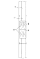
図2A、図2Bは、それぞれ以上で説明した浸透管30の異なる実施形態を示す。
即ち、図2Aに示す浸透管30では、地中に埋設される浸透管部分の全周に亘って排水孔34が設けられており、かつ図2Bの浸透管30では、地中に埋設される部分の略半周のみに排水孔34を設けている。なお、浸透管30の埋設部分の排水孔34の配置は、これらに限ることはなく任意であり、適宜方向性を持たせて目的とする区域に排水することができる。
2A and 2B show different embodiments of the
That is, in the
図3は、浸透管30の配置例を示す斜視図であり、異なる排水孔34の配置構造を備えた浸透管30を任意に組み合わせることで、必要な区域において地下水の涵養を行うことができる。
FIG. 3 is a perspective view showing an example of the arrangement of the
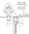
図4は、以上で説明した浸透管30を実際に街路樹の側に設置して、街路樹の根元の地下水の涵養を図る場合の雨水の浸透方向を示す図である。道路面を流れて側溝15に流れ込んだ雨水或いは直接集水桝12に流入した雨水を集水桝12に集め、浸透管30を通して街路樹の根元に確実に給水できるよう、雨水の浸透に方向性を持たせた例である。
FIG. 4 is a diagram showing the infiltration direction of rainwater when the
図5は、図4の実施形態における集水桝12に取付管14を設けたものであり、他の構成は図4のものと同様である。この実施形態では、取付管14を設けたことにより、大量の雨水が流れ込んで集水桝が溢れることが防止出来ると共に、汚染度の高い初期雨水を下水管等に流すことで集水桝12に汚染された雨水を溜込むことがなくなるという利点がある。また、その反面、雨量が少量である場合には、そのまま排出されてしまうことになり、地下への雨水の浸透は行われないことが生じる。なお、集水桝12中の雨水が所定量に達したときに作動する弁を設けて、雨量が所定水位に達したときに始めて取付管14からの排出を開始するような構成を採ることも可能であり、その場合には上記のような問題は生じない。
FIG. 5 shows a
以上の実施形態では、集水桝12中の浸透管30は、降り注ぐ雨水が直接流入することに対してとくに対策は施しておらず、従って、僅かな量ではあるが初期雨水が浸透管30に流入する。従って、このシステムは地下水の汚染が深刻な問題とはならない場合に適している。
しかしながら、地下水を飲料水として利用する地域などでは、その僅かな量の初期雨量でも地下に浸透させないようにする必要がある。
In the above embodiment, the
However, in areas where groundwater is used as drinking water, it is necessary to prevent even a small amount of initial rainfall from penetrating underground.
次に、このような流入防止手段を備えた実施形態について説明する。
図6、図7は、それぞれ図1、図4に対応する図であり、図1及び図4との相違は、浸透管30上に降り注ぐ雨水が該浸透管に直接流入するのを防止するため、集水蓋(グレーチング)16の浸透管30直上部を閉鎖して流入防止手段を構成している点である。また、図6に示す集水蓋16の覆いの縁部分には、雨水が覆いの縁から内側に移動してそこから浸透管30上に落下することがないように、水切りのための突条部16bが設けられている。
なお、集水蓋16に設ける水切り部は、図7中に拡大してA及びBで示すように、突条16c以外に、縁の近傍に溝16bを形成したものでも同様の効果がある。
このように雨水流入防止手段を設けることにより、浸透管30には雨が当たらず、従って、初期雨水が浸透管30に流入することがない。
Next, an embodiment provided with such an inflow prevention means will be described.
FIGS. 6 and 7 are views corresponding to FIGS. 1 and 4, respectively. The difference from FIGS. 1 and 4 is to prevent rainwater that falls on the
In addition, the draining part provided in the water collection lid | cover 16 has the same effect even if what formed the groove |
By providing the rainwater inflow prevention means in this way, the
図8は、図6及び図7に示す集水蓋16の平面図であり、図示のように浸透管30直上部分には雨水の流入孔16aが設けられていない。その他の構成は、図1及び図2に示したものと同様であるので詳細な説明は省略する。このように浸透管30には降り注ぐ雨水が直接流入することが完全に防止されるから、汚染度の高い初期雨水が地下に浸透される恐れはなくなる。
なお、流入防止手段は、要は、浸透管30に降り注ぐ雨水が浸透管30から直接流入することを防止できればよいから、上記の構成に限定するものではなく、浸透管30自体に任意の構成のカバーを被せても同様の効果が得られる。
FIG. 8 is a plan view of the
Note that the inflow prevention means is not limited to the above-described configuration, and is not limited to the above-described configuration, since the rainwater that pours into the
なお、上記取水桝12を構成するコンクリートに炭を混入しておくか、又はその内壁に炭の粉末を吹き付けておくことで、流入する雨水を浄化することもできる。
また、下水道法施行令では、流出側管底下に15cm以上の深さの泥溜めを設置することが規定されているが、本実施形態で浸透管30の開口端の高さHをそれよりも高くすることで、この規定にも適合させることができる。
Inflow rainwater can also be purified by mixing charcoal into the concrete constituting the
In addition, the Sewerage Law Enforcement Ordinance stipulates that a mud reservoir with a depth of 15 cm or more should be installed below the outflow side pipe bottom. In this embodiment, the height H of the open end of the
以上、本発明の実施形態について説明を行ったが、従来の地下浸透施設に比べ、本発明に係る排水システムを構築する場合は、工事量、工事面積、或いは近隣に与える工事の影響、更にコストも低くすることができ、しかも雨水を地下へ効率よく浸透させることができる。 As described above, the embodiment of the present invention has been described. However, when the drainage system according to the present invention is constructed as compared with the conventional underground infiltration facility, the construction amount, the construction area, the influence of construction on the neighborhood, and the cost. Moreover, rainwater can be infiltrated into the basement efficiently.
10・・・汚水桝、12・・・集水桝、14・・・取付管、15・・・側溝、20・・・汚水管(下水管)、22・・・排水管、30・・・浸透管。
DESCRIPTION OF
Claims (8)
前記浸透管は、集水用桝の底から所定距離隔てた雨水を取り入れるための開口その一端部に有すると共に、他端側で前記集水桝の底の下方に配置される部分の周面に雨水浸透孔を複数備えていることを特徴とする浸透管。 A permeation pipe for penetrating through the bottom of a temporary water collecting basin used in a drainage system equipped with a rainwater outflow control facility,
The permeation pipe has an opening for taking in rainwater separated by a predetermined distance from the bottom of the water collecting basin and has one end thereof and a peripheral surface of a portion arranged below the bottom of the water collecting basin at the other end. An infiltration pipe comprising a plurality of rainwater infiltration holes.
前記開口にゴミよけフィルターを備えたことを特徴とする浸透管。 The osmotic tube according to claim 1,
A permeation tube comprising a dust filter in the opening.
前記浸透孔を浸透管の周面の周方向の一部に設けたことを特徴とする浸透管。 In the permeation tube according to claim 1 or 2,
An osmotic tube, wherein the osmotic hole is provided in a part of a circumferential surface of the osmotic tube.
底部に前記請求項1ないし4のいずれかに記載された浸透管を挿通するための孔を有し、浸透管を前記孔に挿通し、その上端開口が前記底部から上方に所定の距離隔て、かつ浸透孔が集水桝の下方に配置されるように一体に取り付けたことを特徴とする浸透管付き集水桝。 A drainage basin with a seepage pipe used in a drainage system equipped with a rainwater outflow control facility,
It has a hole for inserting the osmotic tube according to any one of claims 1 to 4 at the bottom, the osmotic tube is inserted into the hole, and an upper end opening thereof is spaced a predetermined distance upward from the bottom. A drainage basin with an osmotic tube, wherein the permeation holes are integrally attached so as to be disposed below the catchment basin.
浸透管上に降り注ぐ雨水が該浸透管に直接流入するのを阻止するための流入防止手段を備えたことを特徴とする浸透管付き集水桝。 In the catchment with an osmotic tube according to claim 4,
A drainage basin with an osmotic tube, comprising an inflow prevention means for preventing rainwater falling on the osmotic tube from directly flowing into the osmotic tube.
前記流入防止手段は、周縁部に水切り手段を備えた浸透管付き集水桝の蓋であることを特徴とする浸透管付き集水桝。 In the catchment with an osmotic tube according to claim 5,
The drainage basin with an osmotic tube, wherein the inflow prevention means is a lid of the basin with an osmosis tube provided with a draining means at the periphery.
前記数集水桝構成材料に炭を混入又は吹き付けたことを特徴とする浸透管付き集水桝。 In the catchment with an osmotic tube according to any one of claims 4 to 6,
A water collecting tank with a permeation tube, wherein charcoal is mixed or sprayed on the material of the several water tanks.
Priority Applications (1)
| Application Number | Priority Date | Filing Date | Title |
|---|---|---|---|
| JP2004308579A JP4268922B2 (en) | 2004-10-22 | 2004-10-22 | Drainage system with drainage system and drainage system in drainage system |
Applications Claiming Priority (1)
| Application Number | Priority Date | Filing Date | Title |
|---|---|---|---|
| JP2004308579A JP4268922B2 (en) | 2004-10-22 | 2004-10-22 | Drainage system with drainage system and drainage system in drainage system |
Publications (2)
| Publication Number | Publication Date |
|---|---|
| JP2006118265A true JP2006118265A (en) | 2006-05-11 |
| JP4268922B2 JP4268922B2 (en) | 2009-05-27 |
Family
ID=36536394
Family Applications (1)
| Application Number | Title | Priority Date | Filing Date |
|---|---|---|---|
| JP2004308579A Expired - Fee Related JP4268922B2 (en) | 2004-10-22 | 2004-10-22 | Drainage system with drainage system and drainage system in drainage system |
Country Status (1)
| Country | Link |
|---|---|
| JP (1) | JP4268922B2 (en) |
Cited By (18)
| Publication number | Priority date | Publication date | Assignee | Title |
|---|---|---|---|---|
| JP2008008068A (en) * | 2006-06-30 | 2008-01-17 | Tsuneo Kondo | Rainwater collecting device |
| KR100952192B1 (en) | 2010-01-07 | 2010-04-09 | 임철웅 | Water pocket well for infiltrating a rainwater |
| JP2012046916A (en) * | 2010-08-25 | 2012-03-08 | Sekisui Plastics Co Ltd | Drainage structure of underpass part |
| KR101182259B1 (en) * | 2009-12-23 | 2012-09-12 | 한국지질자원연구원 | artificial cultivation system of collected rainwater |
| JP2014095274A (en) * | 2012-11-12 | 2014-05-22 | Sekisui Chem Co Ltd | Rainwater storage and infiltration system |
| US8815288B2 (en) * | 2009-09-30 | 2014-08-26 | Center Laboratories, Inc. | Oral dosage formulation containing both immediate-release and sustained-release drugs for treating neurodegenerative disorders |
| JP2014234643A (en) * | 2013-06-03 | 2014-12-15 | アロン化成株式会社 | Rainwater storage infiltration system |
| JP2016048007A (en) * | 2014-08-28 | 2016-04-07 | 株式会社奥村組 | Permeation basin |
| CN105839759A (en) * | 2016-05-17 | 2016-08-10 | 天津城建大学 | Sandstone seepage well applicable to sponge city construction |
| KR20160097993A (en) * | 2015-02-10 | 2016-08-18 | 한국건설기술연구원 | Rainwater infiltration and catchment induction pipeline implantable unit and rainwater utilization system using the same |
| CN106049641A (en) * | 2016-07-13 | 2016-10-26 | 黑龙江省九0四环境工程勘察设计院 | Back-infiltrating well water filtering device used for rainwater natural purification |
| CN106049642A (en) * | 2016-07-13 | 2016-10-26 | 黑龙江省九0四环境工程勘察设计院 | Sponge city permeation, retention, storage, purification, utilization and water drainage combined system |
| CN107675773A (en) * | 2017-11-17 | 2018-02-09 | 徐万友 | Sewerage system |
| CN107703045A (en) * | 2017-11-09 | 2018-02-16 | 石家庄铁道大学 | Sponge urban green space rainwater-collecting capability analysis system and analysis method |
| JP2020029761A (en) * | 2018-08-25 | 2020-02-27 | 二郎 木原 | Common ditch having flood countermeasure function |
| JP2021021299A (en) * | 2019-07-30 | 2021-02-18 | 株式会社アスカ設計 | Non-overflow type infiltration system and construction method of the same |
| CN112942529A (en) * | 2021-01-26 | 2021-06-11 | 延安大学西安创新学院 | Big or small rainwater reposition of redundant personnel discharging equipment in sponge city |
| CN113818534A (en) * | 2021-09-17 | 2021-12-21 | 中国一冶集团有限公司 | Biological retention facility for sponge urban road |
-
2004
- 2004-10-22 JP JP2004308579A patent/JP4268922B2/en not_active Expired - Fee Related
Cited By (21)
| Publication number | Priority date | Publication date | Assignee | Title |
|---|---|---|---|---|
| JP2008008068A (en) * | 2006-06-30 | 2008-01-17 | Tsuneo Kondo | Rainwater collecting device |
| US8815288B2 (en) * | 2009-09-30 | 2014-08-26 | Center Laboratories, Inc. | Oral dosage formulation containing both immediate-release and sustained-release drugs for treating neurodegenerative disorders |
| KR101182259B1 (en) * | 2009-12-23 | 2012-09-12 | 한국지질자원연구원 | artificial cultivation system of collected rainwater |
| KR100952192B1 (en) | 2010-01-07 | 2010-04-09 | 임철웅 | Water pocket well for infiltrating a rainwater |
| JP2012046916A (en) * | 2010-08-25 | 2012-03-08 | Sekisui Plastics Co Ltd | Drainage structure of underpass part |
| JP2014095274A (en) * | 2012-11-12 | 2014-05-22 | Sekisui Chem Co Ltd | Rainwater storage and infiltration system |
| JP2014234643A (en) * | 2013-06-03 | 2014-12-15 | アロン化成株式会社 | Rainwater storage infiltration system |
| JP2016048007A (en) * | 2014-08-28 | 2016-04-07 | 株式会社奥村組 | Permeation basin |
| KR101656036B1 (en) * | 2015-02-10 | 2016-09-09 | 한국건설기술연구원 | Rainwater infiltration and catchment induction pipeline implantable unit and rainwater utilization system using the same |
| KR20160097993A (en) * | 2015-02-10 | 2016-08-18 | 한국건설기술연구원 | Rainwater infiltration and catchment induction pipeline implantable unit and rainwater utilization system using the same |
| CN105839759A (en) * | 2016-05-17 | 2016-08-10 | 天津城建大学 | Sandstone seepage well applicable to sponge city construction |
| CN106049641A (en) * | 2016-07-13 | 2016-10-26 | 黑龙江省九0四环境工程勘察设计院 | Back-infiltrating well water filtering device used for rainwater natural purification |
| CN106049642A (en) * | 2016-07-13 | 2016-10-26 | 黑龙江省九0四环境工程勘察设计院 | Sponge city permeation, retention, storage, purification, utilization and water drainage combined system |
| CN106049642B (en) * | 2016-07-13 | 2018-08-31 | 黑龙江省九0四环境工程勘察设计院 | A kind of sponge city oozes, is stagnant, storing, net, use, drain combination system |
| CN106049641B (en) * | 2016-07-13 | 2018-12-28 | 黑龙江省九0四环境工程勘察设计院 | It is a kind of to bleed back well water treatment plant for rainwater self-purification |
| CN107703045A (en) * | 2017-11-09 | 2018-02-16 | 石家庄铁道大学 | Sponge urban green space rainwater-collecting capability analysis system and analysis method |
| CN107675773A (en) * | 2017-11-17 | 2018-02-09 | 徐万友 | Sewerage system |
| JP2020029761A (en) * | 2018-08-25 | 2020-02-27 | 二郎 木原 | Common ditch having flood countermeasure function |
| JP2021021299A (en) * | 2019-07-30 | 2021-02-18 | 株式会社アスカ設計 | Non-overflow type infiltration system and construction method of the same |
| CN112942529A (en) * | 2021-01-26 | 2021-06-11 | 延安大学西安创新学院 | Big or small rainwater reposition of redundant personnel discharging equipment in sponge city |
| CN113818534A (en) * | 2021-09-17 | 2021-12-21 | 中国一冶集团有限公司 | Biological retention facility for sponge urban road |
Also Published As
| Publication number | Publication date |
|---|---|
| JP4268922B2 (en) | 2009-05-27 |
Similar Documents
| Publication | Publication Date | Title |
|---|---|---|
| JP4268922B2 (en) | Drainage system with drainage system and drainage system in drainage system | |
| KR101012749B1 (en) | Open-type Initial Rainwater Treatment Equipment | |
| KR101822899B1 (en) | Eco-friendly Surface Water Reservoir for Improvement of Groundwater Storage Function AND Eco-friendly Road Structure With Drainage System Using The Reservoir | |
| CN106917522B (en) | A kind of Outdoor Parking position system based on sponge the idea of the city | |
| JP2009235884A (en) | Outflow restraining drain port for road | |
| JP4284665B2 (en) | Drainage structure of gutter | |
| US10968616B1 (en) | Water drainage system | |
| JP5083602B2 (en) | Spill control street | |
| KR102089235B1 (en) | Multifunctional nonpoint pollution reduction structure | |
| JP2011074563A (en) | Rainwater infiltration system | |
| KR101906075B1 (en) | Road side ditch having seepage paving-material | |
| KR101894740B1 (en) | Manhole for water permeability type | |
| JP2008267023A (en) | Rainwater storage system | |
| JP2004052269A (en) | Manhole and sewer pipe | |
| JP3888857B2 (en) | Rainwater runoff control facility | |
| JPH0786247B2 (en) | Multifunctional gutter | |
| JPH08311938A (en) | Recharge type storage facility | |
| JP2006328640A (en) | Culvert drainage structure and rainwater penetration treating method | |
| KR200224492Y1 (en) | A Percolation Concrete Block for Side Gutter | |
| KR101932601B1 (en) | Eco-friendly Surface Water Reservoir Device for Improvement of Groundwater Storage Function AND Eco-friendly Road Structure With Drainage System Using The Reservoir Device | |
| JP2915389B1 (en) | Filtration type water storage tank device | |
| KR200426719Y1 (en) | A Tunnel Type Rainwater Infitration and Detention System | |
| KR101656668B1 (en) | Equipment for decrease nonpoint pollution sources using vegtation waterway | |
| JPH018616Y2 (en) | ||
| JPH0699954B2 (en) | Multifunctional gutter |
Legal Events
| Date | Code | Title | Description |
|---|---|---|---|
| A621 | Written request for application examination |
Free format text: JAPANESE INTERMEDIATE CODE: A621 Effective date: 20061201 |
|
| A711 | Notification of change in applicant |
Free format text: JAPANESE INTERMEDIATE CODE: A712 Effective date: 20070423 |
|
| A977 | Report on retrieval |
Free format text: JAPANESE INTERMEDIATE CODE: A971007 Effective date: 20080805 |
|
| A131 | Notification of reasons for refusal |
Free format text: JAPANESE INTERMEDIATE CODE: A131 Effective date: 20081024 |
|
| A711 | Notification of change in applicant |
Free format text: JAPANESE INTERMEDIATE CODE: A711 Effective date: 20081104 |
|
| A521 | Written amendment |
Free format text: JAPANESE INTERMEDIATE CODE: A821 Effective date: 20081104 |
|
| A521 | Written amendment |
Free format text: JAPANESE INTERMEDIATE CODE: A523 Effective date: 20081222 |
|
| TRDD | Decision of grant or rejection written | ||
| A01 | Written decision to grant a patent or to grant a registration (utility model) |
Free format text: JAPANESE INTERMEDIATE CODE: A01 Effective date: 20090127 |
|
| A01 | Written decision to grant a patent or to grant a registration (utility model) |
Free format text: JAPANESE INTERMEDIATE CODE: A01 |
|
| A61 | First payment of annual fees (during grant procedure) |
Free format text: JAPANESE INTERMEDIATE CODE: A61 Effective date: 20090223 |
|
| R150 | Certificate of patent (=grant) or registration of utility model |
Free format text: JAPANESE INTERMEDIATE CODE: R150 |
|
| FPAY | Renewal fee payment (prs date is renewal date of database) |
Free format text: PAYMENT UNTIL: 20120227 Year of fee payment: 3 |
|
| FPAY | Renewal fee payment (prs date is renewal date of database) |
Free format text: PAYMENT UNTIL: 20130227 Year of fee payment: 4 |
|
| FPAY | Renewal fee payment (prs date is renewal date of database) |
Free format text: PAYMENT UNTIL: 20140227 Year of fee payment: 5 |
|
| R250 | Receipt of annual fees |
Free format text: JAPANESE INTERMEDIATE CODE: R250 |
|
| LAPS | Cancellation because of no payment of annual fees |