JP2006114196A - Solid immersion lens, focusing lens using the same, optical pickup apparatus, optical recording and reproducing apparatus and method of manufacturing solid immersion lens - Google Patents
Solid immersion lens, focusing lens using the same, optical pickup apparatus, optical recording and reproducing apparatus and method of manufacturing solid immersion lens Download PDFInfo
- Publication number
- JP2006114196A JP2006114196A JP2005045736A JP2005045736A JP2006114196A JP 2006114196 A JP2006114196 A JP 2006114196A JP 2005045736 A JP2005045736 A JP 2005045736A JP 2005045736 A JP2005045736 A JP 2005045736A JP 2006114196 A JP2006114196 A JP 2006114196A
- Authority
- JP
- Japan
- Prior art keywords
- solid immersion
- immersion lens
- lens
- optical
- convex portion
- Prior art date
- Legal status (The legal status is an assumption and is not a legal conclusion. Google has not performed a legal analysis and makes no representation as to the accuracy of the status listed.)
- Abandoned
Links
Images


Classifications
-
- G—PHYSICS
- G11—INFORMATION STORAGE
- G11B—INFORMATION STORAGE BASED ON RELATIVE MOVEMENT BETWEEN RECORD CARRIER AND TRANSDUCER
- G11B7/00—Recording or reproducing by optical means, e.g. recording using a thermal beam of optical radiation by modifying optical properties or the physical structure, reproducing using an optical beam at lower power by sensing optical properties; Record carriers therefor
- G11B7/12—Heads, e.g. forming of the optical beam spot or modulation of the optical beam
- G11B7/135—Means for guiding the beam from the source to the record carrier or from the record carrier to the detector
- G11B7/1372—Lenses
- G11B7/1374—Objective lenses
-
- G—PHYSICS
- G02—OPTICS
- G02B—OPTICAL ELEMENTS, SYSTEMS OR APPARATUS
- G02B13/00—Optical objectives specially designed for the purposes specified below
-
- G—PHYSICS
- G11—INFORMATION STORAGE
- G11B—INFORMATION STORAGE BASED ON RELATIVE MOVEMENT BETWEEN RECORD CARRIER AND TRANSDUCER
- G11B7/00—Recording or reproducing by optical means, e.g. recording using a thermal beam of optical radiation by modifying optical properties or the physical structure, reproducing using an optical beam at lower power by sensing optical properties; Record carriers therefor
- G11B7/12—Heads, e.g. forming of the optical beam spot or modulation of the optical beam
- G11B7/135—Means for guiding the beam from the source to the record carrier or from the record carrier to the detector
- G11B7/1372—Lenses
- G11B2007/13727—Compound lenses, i.e. two or more lenses co-operating to perform a function, e.g. compound objective lens including a solid immersion lens, positive and negative lenses either bonded together or with adjustable spacing
Abstract
Description
本発明は、ソリッドイマージョンレンズ(Solid Immersion Lens:固浸レンズ)と、これを用いた集光レンズ、光学ピックアップ装置及び光(もしくは光磁気)記録再生装置、またソリッドイマージョンレンズの形成方法に関し、さらに詳しくは、光学レンズの屈折率が大なる材料を用いて集光レンズの開口数を大にして光(もしくは光磁気)記録媒体に記録再生を行ういわゆるニアフィールド光記録再生方式に好適なソリッドイマージョンレンズとこれを用いた集光レンズ、光学ピックアップ装置、光記録再生装置及びソリッドイマージョンレンズの形成方法に関するものである。 The present invention relates to a solid immersion lens (Solid Immersion Lens), a condensing lens using the same, an optical pickup device and an optical (or magneto-optical) recording / reproducing device, and a method for forming a solid immersion lens. Specifically, a solid immersion suitable for a so-called near-field optical recording / reproducing system that performs recording / reproducing on an optical (or magneto-optical) recording medium by using a material having a high refractive index of the optical lens and increasing the numerical aperture of the condenser lens. The present invention relates to a lens, a condensing lens using the same, an optical pickup device, an optical recording / reproducing device, and a solid immersion lens forming method.
コンパクトディスク(CD)、ミニディスク(MD)、デジタルヴァーサタイルディスク(DVD)に代表される光記録媒体(光磁気記録媒体を含む)は、音楽情報、映像情報、データ、プログラム等の格納媒体として広く利用されている。しかしながら、更なる音楽情報、映像情報、データ、プログラム等の高音質化、高画質化、長時間化、大容量化のために、さらに大容量の光記録媒体及びこれを記録再生する光記録再生装置(光磁気記録再生装置を含む)が望まれている。
そこで、これらに対応するため、光記録再生装置では、その光源の例えば半導体レーザの短波長化や、集光レンズの開口数の増大化が図られ、集光レンズを介して収束する光スポットの小径化が図られている。
Optical recording media (including magneto-optical recording media) represented by compact disc (CD), mini disc (MD), and digital versatile disc (DVD) are used as storage media for music information, video information, data, programs, and the like. Widely used. However, for higher sound quality, higher image quality, longer time, and larger capacity of music information, video information, data, programs, etc., a larger capacity optical recording medium and optical recording / reproducing for recording / reproducing the same An apparatus (including a magneto-optical recording / reproducing apparatus) is desired.
Therefore, in order to cope with these, in the optical recording / reproducing apparatus, the wavelength of the light source, for example, the semiconductor laser is shortened, the numerical aperture of the condensing lens is increased, and the light spot converged through the condensing lens is reduced. The diameter has been reduced.
例えば、半導体レーザに関しては、発振波長が従来の赤色レーザの635nmから400nm帯に短波長化されたGaN半導体レーザが実用化され、これにより光スポットの小径化が図られつつある。また、例えばそれ以上の短波長化については、266nmの単一波長の光を連続発振するソニー(株)製の遠紫外固体レーザUW−1020A(商品名)などが発売されており、更なる光スポットの小径化も図られつつある。また、これ以外にもNd:YAGレーザの2倍波レーザ(266nm帯)、ダイヤモンドレーザ(235nm帯)、GaNレーザの2倍波レーザ(202nm帯)などの研究、開発が進められている。 For example, with regard to semiconductor lasers, GaN semiconductor lasers whose oscillation wavelength has been shortened from the 635 nm to 400 nm bands of conventional red lasers have been put into practical use, and thereby the diameter of the light spot is being reduced. For further shortening of the wavelength, for example, a far ultraviolet solid-state laser UW-1020A (trade name) manufactured by Sony Corporation that continuously oscillates light having a single wavelength of 266 nm has been put on the market. Spot diameters are also being reduced. In addition to this, research and development of a Nd: YAG laser double wave laser (266 nm band), a diamond laser (235 nm band), a GaN laser double wave laser (202 nm band), and the like are underway.
また、ソリッドイマ―ジョンレンズ(SIL)に代表される開口数の大なる光学レンズを使って、例えば開口数1以上の集光レンズを実現するとともに、この集光レンズの対物面を光記録媒体と、その光源波長の10分の1程度まで近接させることにより記録再生を行ういわゆるニアフィールド光記録再生方式が検討されている(例えば特許文献1参照。)。 Further, by using an optical lens having a large numerical aperture represented by a solid immersion lens (SIL), for example, a condensing lens having a numerical aperture of 1 or more is realized, and the objective surface of the condensing lens is used as an optical recording medium. Then, a so-called near-field optical recording / reproducing system in which recording / reproducing is performed by bringing the light source wavelength close to about one-tenth of the light source wavelength has been studied (for example, see Patent Document 1).
このニアフィールド光記録再生方式では、光記録媒体と集光レンズとの距離を精度良く光学的なコンタクト状態に維持することが重要である。また、光源から出射されて集光レンズに入射する光束径が小になるとともに、光記録媒体と集光レンズとの距離も数十nm以下程度と非常に小さくなるため、光記録媒体と集光レンズとの傾きマージン、いわゆるチルトマージンが非常に小さくなり、集光レンズは形状的に大きく制約されることになる。 In this near-field optical recording / reproducing system, it is important to maintain the distance between the optical recording medium and the condenser lens in an optical contact state with high accuracy. In addition, the diameter of the light beam emitted from the light source and incident on the condensing lens becomes small, and the distance between the optical recording medium and the condensing lens is very small, about tens of nm or less. The tilt margin with the lens, the so-called tilt margin, becomes very small, and the condensing lens is greatly restricted in shape.
図18に、ソリッドイマージョンレンズの一例の概略構成図を示す。ソリッドイマージョンレンズ11と光学レンズ12とを、光記録媒体10(光磁気記録媒体を含む)と対向する対物側から順に配置して、ニアフィールド集光レンズを構成することができる。図18に示すように、ソリッドイマージョンレンズ11は、曲率半径rの半球状又は超半球状(図示の例においては超半球状)に形成され、光軸に沿う厚さが半球状の場合はrとされ、図示の例のように超半球状とする場合は、屈折率をnとすると光軸に沿う厚さがr(1+1/n)として構成される。
FIG. 18 shows a schematic configuration diagram of an example of a solid immersion lens. The
このような構成の集光レンズを例えば光記録再生装置に適用する場合は、2軸アクチュエータを有する光学ピックアップ装置に装着され、光記録媒体と集光レンズとの距離を光学的なコンタクト状態に維持する。光磁気記録に用いられる場合は、光学ピックアップ装置に、磁気記録再生に使用される磁気ヘッド装置が組み込まれ、同様に光記録媒体と集光レンズとの距離を光学的なコンタクト状態に維持する構成とされる。
ところで、上述のニアフィールド光記録再生方式では、光記録媒体に対するフォーカシング方向及び/又はトラッキング方向に制御駆動される集光レンズの安定制御を図るとともに、光記録媒体の安定した記録再生が行えるように、光記録媒体とその集光レンズの対物面の傾きマージンをある程度保持する必要がある。 By the way, in the above-mentioned near-field optical recording / reproducing system, stable control of the condenser lens controlled and driven in the focusing direction and / or tracking direction with respect to the optical recording medium is achieved, and stable recording / reproduction of the optical recording medium can be performed. It is necessary to maintain a certain degree of tilt margin between the objective surface of the optical recording medium and its condenser lens.
そこで、本出願人は、先の出願(特願2004−73161号出願に基づいて優先権主張した特願2005−34884号出願、特願2004−73162号出願に基づいて優先権主張した特願2005−18662号出願)において、ソリッドイマージョンレンズの対物側に凸状部、例えば、円錐形状、角錐形状等の凸状部を設け、かつその先端部分を平面状に加工して対物面とすることにより、対物面と光記録媒体との距離を数十nmにした場合でも、傾きマージンが、±0.1度程度確保できるよう加工されたソリッドイマージョンレンズを提案した。これにより、記録再生特性の安定化を図ることが可能な光学ピックアップ装置、光記録再生装置を提供することができる。 Therefore, the applicant of the present application (Japanese Patent Application No. 2005-34884 that claimed priority based on Japanese Patent Application No. 2004-73161) and Japanese Patent Application No. 2005 that claimed priority based on Japanese Patent Application No. 2004-73162. No. 18862 application), a convex portion such as a cone shape or a pyramid shape is provided on the object side of the solid immersion lens, and the tip portion is processed into a flat surface to obtain an object surface. The present inventors have proposed a solid immersion lens that has been processed so that an inclination margin of about ± 0.1 degrees can be secured even when the distance between the objective surface and the optical recording medium is several tens of nanometers. Thereby, it is possible to provide an optical pickup device and an optical recording / reproducing device capable of stabilizing the recording / reproducing characteristics.
ところで、このように凸状部を対物側に設けるソリッドイマージョンレンズでは、ソリッドイマージョンレンズの開口数NAが大きくなるほど、すなわち、レーザの入射角度が大きくなるほど、レーザの入射光路を遮らないように凸状部の加工角度を小さく、例えば円錐形状の場合、その円錐の頂角の角度を大きくする必要がある。
その結果、開口数NAの大きなソリッドイマージョンレンズを保持するレンズ保持体との接着面積が小さくなってしまい、僅かな衝撃で保持体がはずれてしまう恐れがある。
By the way, in the solid immersion lens in which the convex portion is provided on the object side in this way, the convex shape is formed so as not to block the incident optical path of the laser as the numerical aperture NA of the solid immersion lens increases, that is, as the incident angle of the laser increases. For example, in the case of a conical shape, it is necessary to increase the apex angle of the cone.
As a result, the adhesion area with the lens holding body that holds the solid immersion lens having a large numerical aperture NA becomes small, and the holding body may be detached by a slight impact.
同様に、このソリッドイマージョンレンズを保持するレンズ保持体との接着面積は、ソリッドイマージョンレンズの球状部の半径が小さくなるほど、またソリッドイマージョンレンズの屈折率が大きくなるほど小さくなる。更に、レーザの入射角度が大きくなるほど、凸状部の先端の集光平面部(すなわち対物面)の半径が大きくなるほど、同様に小さくなってしまう。 Similarly, the adhesion area with the lens holder that holds the solid immersion lens decreases as the radius of the spherical portion of the solid immersion lens decreases and as the refractive index of the solid immersion lens increases. Further, the larger the incident angle of the laser, the smaller the radius of the condensing flat surface portion (that is, the objective surface) at the tip of the convex portion.
特に、今後の光記録媒体の高密度化、光ピックアップ装置の小型・軽量化に対する要求を満たすためには、ソリッドイマージョンレンズの高開口数化と、ソリッドイマージョンレンズの微小化を実現しなければならないため、ソリッドイマージョンレンズを保持するレンズ保持体との接着面積が微小化されても、安定にソリッドイマージョンレンズを固着し、保持する必要がある。 In particular, in order to meet future demands for higher density optical recording media and smaller and lighter optical pickup devices, it is necessary to increase the numerical aperture of solid immersion lenses and miniaturize solid immersion lenses. Therefore, even if the adhesion area with the lens holder that holds the solid immersion lens is miniaturized, it is necessary to stably fix and hold the solid immersion lens.
以上の課題に鑑みて、本発明は、ソリッドイマージョンレンズとレンズ保持体との接着状態を良好に保持するソリッドイマージョンレンズとこれを用いた集光レンズ、光学ピックアップ装置、光記録再生装置及びソリッドイマージョンレンズの形成方法を提供することを目的とする。 In view of the above problems, the present invention provides a solid immersion lens that satisfactorily maintains a bonding state between a solid immersion lens and a lens holder, a condensing lens using the same, an optical pickup device, an optical recording / reproducing device, and a solid immersion It is an object to provide a method for forming a lens.
上記課題を解決するため、本発明は、ソリッドイマージョンレンズの対物側に、対物面に向かって突出する凸状部を設け、この凸状部の少なくとも一部に、段差もしくは凹部を設ける構成とする。
また、本発明は、上述のソリッドイマージョンレンズにおいて、上記凹部が、上記ソリッドイマージョンレンズを保持する保持体との接着領域の少なくとも一部に設けられて成ることを特徴とする。
更に、本発明は、上述のソリッドイマージョンレンズにおいて、上記段差が、上記ソリッドイマージョンレンズの光軸に沿う断面において、上記光軸に対し異なる角度をもって傾斜する2以上の傾斜面より構成されることを特徴とする。
In order to solve the above problems, the present invention has a configuration in which a convex portion protruding toward the objective surface is provided on the objective side of the solid immersion lens, and a step or a concave portion is provided in at least a part of the convex portion. .
Further, the present invention is characterized in that, in the above-described solid immersion lens, the concave portion is provided in at least a part of an adhesion region with a holding body that holds the solid immersion lens.
Furthermore, the present invention is the above-described solid immersion lens, wherein the step is constituted by two or more inclined surfaces inclined at different angles with respect to the optical axis in a cross section along the optical axis of the solid immersion lens. Features.
また、本発明は、上述の本発明によるソリッドイマージョンレンズを用いて集光レンズ、光学ピックアップ装置及び光記録再生装置を構成するものである。
すなわち、本発明による集光レンズは、ソリッドイマージョンレンズと、該ソリッドイマージョンレンズと光軸を合致させ、対物側とは反対側に配置された光学レンズとより構成された集光レンズにおいて、上記ソリッドイマージョンレンズの対物側に、集光部に向かって突出する凸状部が設けられ、上記凸状部の少なくとも一部に段差もしくは凹部が設けられて成ることを特徴とする。
また、本発明による光学ピックアップ装置は、少なくとも、光源と、光軸を合致させて対物側から順に配置されたソリッドイマージョンレンズと光学レンズとで構成され、上記光源からの出射光を収束させて光スポットを形成する集光レンズとを有する光学ピックアップ装置において、上記ソリッドイマージョンレンズの対物側に、集光部に向かって突出する凸状部が設けられ、上記凸状部の少なくとも一部に段差もしくは凹部が設けられて成ることを特徴とする。
Further, the present invention constitutes a condenser lens, an optical pickup device, and an optical recording / reproducing device using the solid immersion lens according to the present invention described above.
That is, the condensing lens according to the present invention is a condensing lens composed of a solid immersion lens and an optical lens that is aligned with the optical axis of the solid immersion lens and disposed on the side opposite to the objective side. A convex portion that protrudes toward the condensing portion is provided on the objective side of the immersion lens, and a step or a concave portion is provided on at least a part of the convex portion.
The optical pickup device according to the present invention includes at least a light source, a solid immersion lens and an optical lens that are arranged in order from the object side with the optical axis aligned, and converges the light emitted from the light source to provide light. In the optical pickup device having a condensing lens that forms a spot, a convex portion that protrudes toward the condensing portion is provided on the objective side of the solid immersion lens, and a step or a step is provided on at least a part of the convex portion. A concave portion is provided.
更に、本発明による光記録再生装置は、集光レンズにより光記録媒体の記録位置に光を集光して記録及び/又は再生を行う光学ピックアップ装置を有し、上記集光レンズ及び上記光学ピックアップ装置を上記光記録媒体のフォーカシング方向及び/又はトラッキング方向に制御駆動する制御駆動手段が少なくとも設けられて成る光記録再生装置において、上記集光レンズは、少なくともその対物側にソリッドイマージョンレンズが配置され、上記ソリッドイマージョンレンズの対物側に、集光部に向かって突出する凸状部が設けられ、上記凸状部の少なくとも一部に段差もしくは凹部が設けられて成ることを特徴とする。
また、本発明によるソリッドイマージョンレンズの形成方法は、ソリッドイマージョンレンズの対物側に、集光部に向かって突出する凸状部を形成し、上記凸状部の少なくとも一部に段差もしくは凹部をフォーカスイオンビーム加工方法により形成することを特徴とする。
The optical recording / reproducing apparatus according to the present invention further includes an optical pickup device that performs recording and / or reproduction by condensing light at a recording position of the optical recording medium by a condensing lens, and the condensing lens and the optical pickup. In the optical recording / reproducing apparatus comprising at least control drive means for controlling and driving the apparatus in the focusing direction and / or the tracking direction of the optical recording medium, the condenser lens has a solid immersion lens disposed at least on the objective side thereof. A convex portion that protrudes toward the light condensing portion is provided on the object side of the solid immersion lens, and a step or a concave portion is provided on at least a part of the convex portion.
In the solid immersion lens forming method according to the present invention, a convex portion projecting toward the condensing portion is formed on the objective side of the solid immersion lens, and a step or a concave portion is focused on at least a part of the convex portion. It is formed by an ion beam processing method.
上述したように、本発明によるソリッドイマージョンレンズは、その対物側に、対物面に向かって突出する凸状部を設け、この凸状部の少なくとも一部に、段差もしくは凹部を設けることから、このソリッドイマージョンレンズを保持する保持体と対向する面積を大とすることができる。
特に、このソリッドイマージョンレンズにおいて、ソリッドイマージョンレンズを保持する保持体との接着領域の少なくとも一部に凹部を設けることによって、接着剤がソリッドイマージョンレンズと接触する面積が確実に大となる。したがって、ソリッドイマージョンレンズを微小化し、また開口数を大とするために入射角度を大とする場合においても、安定な固着に十分な接着面積を確保することが可能となる。
また、凸状部に段差を設ける場合、この段差を、ソリッドイマージョンレンズの光軸に沿う断面において、光軸に対し異なる角度をもって傾斜する2以上の傾斜面より構成する場合は、保持体と接着する外周側部分において、光軸側部分よりも光軸に対し鋭角となる(すなわち対物面とはより大なる角度をもって)傾斜面を構成すれば、開口数を大とするために入射光角度を大とし、これに合わせて凸状部の対物側を光軸から大なる角度で構成する場合においても、開口数の比較的低い場合と同程度以上に保持体との接着面積を確保することができる。
As described above, the solid immersion lens according to the present invention has a convex portion protruding toward the objective surface on the objective side, and a step or a concave portion is provided on at least a part of the convex portion. The area facing the holding body that holds the solid immersion lens can be increased.
In particular, in this solid immersion lens, by providing the concave portion in at least a part of the adhesion region with the holding body that holds the solid immersion lens, the area where the adhesive contacts the solid immersion lens is surely increased. Accordingly, even when the solid immersion lens is miniaturized and the incident angle is increased in order to increase the numerical aperture, it is possible to ensure a sufficient bonding area for stable fixation.
Further, when a step is provided on the convex portion, the step is bonded to the holding body when the step is constituted by two or more inclined surfaces inclined at different angles with respect to the optical axis in the cross section along the optical axis of the solid immersion lens. If an inclined surface is formed with an acute angle with respect to the optical axis than the optical axis side portion (that is, at a larger angle with respect to the objective surface), the incident light angle is set to increase the numerical aperture. In accordance with this, even when the objective side of the convex portion is configured with a large angle from the optical axis, it is possible to secure an adhesion area with the holding body at least as much as when the numerical aperture is relatively low. it can.
したがって、このような本発明によるソリッドイマージョンレンズを用いて集光レンズ、光学ピックアップ装置及び光記録再生装置を構成することにより、レンズ保持体とソリッドイマージョンレンズとの接着面積をより確保できて、安定にレンズを保持することができる。
そして、本発明によるソリッドイマージョンレンズの形成方法では、上述したソリッドイマージョンレンズの段差や凹部をフォーカスイオンビーム加工方法により形成するため、段差や凹部の形状を精度良く形成することができる。
Therefore, by constructing a condensing lens, an optical pickup device, and an optical recording / reproducing device using such a solid immersion lens according to the present invention, a bonding area between the lens holder and the solid immersion lens can be secured more stably. Can hold the lens.
In the solid immersion lens forming method according to the present invention, the steps and recesses of the solid immersion lens described above are formed by the focus ion beam processing method, so that the shapes of the steps and recesses can be formed with high accuracy.
以上説明したように、本発明のソリッドイマージョンレンズによれば、ソリッドイマージョンレンズの対物側に、対物面に向かって突出する凸状部を設け、この凸状部の少なくとも一部に、段差もしくは凹部を設けることにより、レンズ保持体との接着面積を大として、従来と比較してより安定な保持が可能となる。 As described above, according to the solid immersion lens of the present invention, a convex portion that protrudes toward the objective surface is provided on the objective side of the solid immersion lens, and a step or a concave portion is provided on at least a part of the convex portion. By providing a large area of adhesion to the lens holder, more stable holding can be achieved compared to the conventional case.
更に、本発明による集光レンズ、光学ピックアップ装置及び光記録再生装置によれば、集光レンズに用いるソリッドイマージョンレンズを安定に保持することができ、開口数を大としたソリッドイマージョンレンズを用いて光記録媒体に対する安定走行の可能な光学ピックアップ装置及び光記録再生装置を提供することができる。
また、本発明によるソリッドイマージョンレンズの形成方法によれば、比較的安定した保持の可能なソリッドイマージョンレンズを、入射光への影響を及ぼすことなく精度良く形成することができる。
Furthermore, according to the condensing lens, the optical pickup device, and the optical recording / reproducing apparatus according to the present invention, the solid immersion lens used for the condensing lens can be stably held, and the solid immersion lens having a large numerical aperture is used. It is possible to provide an optical pickup device and an optical recording / reproducing device capable of stable running with respect to an optical recording medium.
Further, according to the method of forming a solid immersion lens according to the present invention, a solid immersion lens that can be held relatively stably can be accurately formed without affecting incident light.
以下本発明を実施するための最良の形態の例を説明するが、本発明は以下の例に限定されるものではない。
本発明は、ソリッドイマージョンレンズと、このソリッドイマージョンレンズと光軸を合致させ、対物側とは反対側に配置された光学レンズとで構成された集光レンズ、更にこの集光レンズを有し、いわゆるニアフィールド光記録再生方式を採用する光学ピックアップ装置と、この光学ピックアップ装置を有する光記録再生装置に適用することができる。
Examples of the best mode for carrying out the present invention will be described below, but the present invention is not limited to the following examples.
The present invention has a condensing lens composed of a solid immersion lens, an optical lens that is aligned with the optical axis of the solid immersion lens and disposed on the side opposite to the objective side, and further includes the condensing lens. The present invention can be applied to an optical pickup apparatus that employs a so-called near-field optical recording / reproducing system and an optical recording / reproducing apparatus having the optical pickup apparatus.
まず、本発明によるソリッドイマージョンレンズの説明に先立って、これら集光レンズ、光学ピックアップ装置、光記録再生装置に適用した実施の形態の例について図1〜図3を参照して説明する。なお、図1〜図3において、ソリッドイマージョンレンズの形状は、その配置構成を容易に説明するために、本発明構成による一例を簡略化して示すもので
あるが、後述する図4以後の例を含む本発明構成の形状を採り得るものである。
First, prior to the description of the solid immersion lens according to the present invention, examples of embodiments applied to the condenser lens, the optical pickup device, and the optical recording / reproducing device will be described with reference to FIGS. In FIG. 1 to FIG. 3, the shape of the solid immersion lens is shown by simplifying an example according to the configuration of the present invention in order to easily explain the arrangement configuration. Including the shape of the present invention configuration.
図1は、本発明によるソリッドイマージョンレンズを用いた集光レンズの一例を示す概略構成図である。レンズの対象物の例えば光記録媒体10に対向して、本発明構成によるソリッドイマージョンレンズ11、光学レンズ12をこの順に光軸を合致させて配置して構成する。ソリッドイマージョンレンズ11は、半径rの半球状又は超半球状とされ、その光軸に沿う厚さは、半球状とする場合はr、超半球状とする場合は屈折率をnとするとr(1+1/n)とされる。このような構成とすることによって、光学レンズ12の開口数NAを超える高開口数の集光レンズ13を提供することができる。
なお、実際にはソリッドイマージョンレンズ11と光記録媒体10とは互いに接触してはいないが、これらソリッドイマージョンレンズ11及び光記録媒体10の間隔はソリッドイマージョンレンズ11の厚さと比較して十分に小さいため図1〜図3においてはその間隔を省略して示す。
FIG. 1 is a schematic configuration diagram showing an example of a condensing lens using a solid immersion lens according to the present invention. A
Actually, the
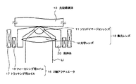
図2は、図1に示すソリッドイマージョンレンズ及び集光レンズを用いた光学ピックアップ装置の光学系の構成の一形態を示す概略構成図である。図示しない光源及びフォトディテクタと、ソリッドイマージョンレンズ11及び光学レンズ12より成る集光レンズ13との間に、例えば第1及び第2のビームスプリッタ14及び15が配置される。光記録媒体10は、例えばディスク状であれば、図示を省略するスピンドルモータに装着され、所定の回転数で回転される。
FIG. 2 is a schematic configuration diagram showing an example of the configuration of the optical system of the optical pickup device using the solid immersion lens and the condenser lens shown in FIG. For example, first and second beam splitters 14 and 15 are arranged between a light source and a photodetector (not shown) and a
また、図1及び図2に示す光学ピックアップ装置には、集光レンズ13をトラッキング方向及びフォーカシング方向に制御駆動する手段が設けられる。
この手段としては、例えば一般的な光学ピックアップに用いられる2軸アクチュエータや、磁気ヘッド装置等に用いられるスライダ等が挙げられる。
これら集光レンズ13の制御駆動手段の形態を次に示す。
The optical pickup device shown in FIGS. 1 and 2 is provided with means for controlling and driving the
Examples of this means include a biaxial actuator used for a general optical pickup and a slider used for a magnetic head device.
The form of the control drive means of these condensing
図3は、本発明の光記録再生装置の一部を構成する光学ピックアップ装置の一例であって、制御駆動手段として2軸アクチュエータを用いた光学ピックアップ装置の一例の概略構成図を示す。図3に示すように、集光レンズ13は、そのソリッドイマージョンレンズ11及び光学レンズ12の光軸を合致させて保持体20により固定され、この保持体20がフォーカシング方向及び/又はトラッキング方向に制御駆動される2軸アクチュエータ16に固着されている。
図3に示すように、2軸アクチュエータ16は、集光レンズ13をトラッキング方向に制御駆動させるトラッキング用コイル17と、フォーカシング方向に制御駆動させるフォーカシング用コイル18とより構成される。
FIG. 3 is a schematic configuration diagram of an example of an optical pickup apparatus that constitutes a part of the optical recording / reproducing apparatus of the present invention and that uses a biaxial actuator as a control drive unit. As shown in FIG. 3, the
As shown in FIG. 3, the biaxial actuator 16 includes a tracking coil 17 for controlling and driving the
そしてこの2軸アクチュエータ16により、光記録媒体10とソリッドイマージョンレンズ11との距離を、例えば戻り光量をモニタし、その距離情報をフィードバックすることにより制御可能とし、ソリッドイマージョンレンズ11と光記録媒体10との距離をほぼ一定に保つようになされ、かつこのソリッドイマージョンレンズ11と光記録媒体10との衝突を避けるように制御される。
また、この2軸アクチュエータ16において、トラッキング方向に戻り光量をモニタし、その位置情報をフィードバックすることにより、集光スポットを所望の記録トラックに移動させることが可能である。
The distance between the
Further, in this biaxial actuator 16, it is possible to move the focused spot to a desired recording track by monitoring the amount of light returning in the tracking direction and feeding back the position information.
以下、光学ピックアップ装置の概略構成について、再び図2を参照して説明する。光源、例えば半導体レーザから出射された往路光はコリメータレンズ(図示せず)により平行光に変換され(L1)、第1のビームスプリッタ14を透過し(L)、集光レンズ13を介して光記録媒体10の情報記録面に集光される。情報記録面で反射された復路光は集光
レンズ13を透過し、第1のビームスプリッタ14で反射され(L2)、第2のビームスプリッタ15に入射する。そしてこの第2のビームスプリッタ15により分離された復路光(L3及びL4)は、フォーカシング用光検出器及び信号用光検出器(図示せず)に集光され、フォーカスシングエラー信号および再生ピット信号等が検出される。
Hereinafter, a schematic configuration of the optical pickup device will be described with reference to FIG. 2 again. Outgoing light emitted from a light source, for example, a semiconductor laser, is converted into parallel light by a collimator lens (not shown) (L1), passes through the first beam splitter 14 (L), and passes through the
また、第2のビームスプリッタで反射された復路光は、例えばトラッキング用光検出器に集光され、トラッキングエラー信号が検出される。なお、必要に応じてこの光学ピックアップ装置には、光記録媒体30の面振れに対して、集光レンズ13を固着する2軸アクチュエータが追従し残したフォーカスエラー成分及び集光レンズの組み立て工程時に発生した誤差成分を、2枚のレンズの間隔を変えることで補正することができるリレーレンズを、第1のビームスプリッタ14と光学レンズ12との間に挿入し構成してもよい。
Further, the return light reflected by the second beam splitter is condensed, for example, on a tracking photodetector, and a tracking error signal is detected. If necessary, the optical pickup device includes a focus error component left behind by the biaxial actuator for fixing the
また、図示しないが集光レンズをスライダに搭載する場合は、スライダが追従した残りのフォーカスエラー成分および集光レンズの組み立て工程時に発生した誤差成分を補正する手段として、集光レンズをスライダに固定し、光学レンズを例えば圧電素子等により光軸方向に可動するように構成してもよい。
また、スピンドルモータが複数の光記録媒体を装着する手段を有する光記録再生装置の場合は、光軸をほぼ90度曲げるミラーをスライダに設ける構成が好適である。このような構成の光記録再生装置は、光記録媒体間の間隔を小とすることができるので、結果的に装置の小型化、薄型化を図ることができる。
Although not shown, when the condenser lens is mounted on the slider, the condenser lens is fixed to the slider as a means to correct the remaining focus error component that the slider followed and the error component generated during the condenser lens assembly process. The optical lens may be configured to be movable in the optical axis direction by, for example, a piezoelectric element.
Further, in the case of an optical recording / reproducing apparatus in which the spindle motor has means for mounting a plurality of optical recording media, it is preferable that the slider is provided with a mirror that bends the optical axis approximately 90 degrees. In the optical recording / reproducing apparatus having such a configuration, the interval between the optical recording media can be reduced, and as a result, the apparatus can be reduced in size and thickness.
なお、上記した光学ピックアップ装置は、再生のみを行う再生専用、記録のみを行う記録専用、記録と再生の両方を行うことができる記録再生用を含むものである。また、上述した各光学ピックアップ装置は、光磁気記録方式と、ニアフィールド光再生方式を組み合わせることにより、その光ピックアップ装置の一部に磁気コイル等を組み込んだものを含む構成とすることもできる。熱磁気記録再生方式を採用する場合おいても同様である。また、光記録再生装置は、再生のみを行う再生専用装置、記録のみを行う記録専用装置、記録と再生の両方を行うことができる記録再生用装置を含むものである。 The above-described optical pickup device includes a reproduction-only unit that performs only reproduction, a recording-only unit that performs only recording, and a recording / reproducing unit that can perform both recording and reproduction. In addition, each of the optical pickup devices described above can be configured to include a device in which a magnetic coil or the like is incorporated in a part of the optical pickup device by combining the magneto-optical recording method and the near-field light reproducing method. The same applies to the case where the thermomagnetic recording / reproducing system is employed. The optical recording / reproducing apparatus includes a reproduction-only apparatus that performs only reproduction, a recording-only apparatus that performs only recording, and a recording / reproduction apparatus that can perform both recording and reproduction.
次に、本発明のソリッドイマージョンレンズに適用して好適なレンズ形状の例について説明する。
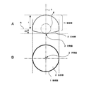
図4A及びBは、本発明によるソリッドイマージョンレンズの一例の概略側面図及び概略平面図を示す。この例においては、球状部1を曲率半径rの超半球状とした場合を示し、屈折率をnとすると、光軸cに沿う方向の厚さをr(1+1/n)として、対物側に、対物面3に向かって突出する凸状部2を設けるものである。
図4において、破線Rは、ソリッドイマージョンレンズ11の光軸と直交する断面において、半径がrとなる断面を示す。
そして本発明のソリッドイマージョンレンズ11において、凸状部2の形状としては、円錐形状や角錐形状としてもよい。
Next, an example of a lens shape suitable for application to the solid immersion lens of the present invention will be described.
4A and 4B show a schematic side view and a schematic plan view of an example of a solid immersion lens according to the present invention. In this example, the spherical portion 1 is shown as a super hemisphere with a radius of curvature r, where the refractive index is n, the thickness in the direction along the optical axis c is r (1 + 1 / n), The
In FIG. 4, a broken line R indicates a cross section having a radius r in a cross section orthogonal to the optical axis of the
In the
また、図5A及びBに示すように、球状部1を半球状として、その厚さをrとし、凸状部2が略円錐形状、又は角錐形状とする例において、先端部の対物面3を、例えば半径が略r/2の破線fで示す球に略外接する形状としてもよい。この場合は、レーザ等の入射光の光軸が、レンズ11の光軸から僅かに傾いた場合においても、入射光がソリッドイマージョンレンズ11内を通過する距離が変化することがなく、良好に対物面に集光させることができるという利点を有する。
また、図6A及びBに示すように、球状部1を超半球状として、その厚さをr/nとし、凸状部2を略円錐形状、又は角錐形状とする例において、先端部の対物面3を、例えば半径が略r/nの一点鎖線gで示す球に略外接する形状としてもよい。この場合も、レーザ等の入射光の光軸が、レンズ11の光軸から僅かに傾いた場合においても、入射光がソリッドイマージョンレンズ11内を通過する距離が変化することがなく、良好に対物面に集光させることができるという利点を有する。
更に、図7A及びBに示すように、凸状部2を、例えば球面を含む各種の曲面状とすることもできる。
図5A及びB、図6A及びB、図7A及びBにおいて、図4A及びBと対応する部分には同一符号を付して重複説明を省略する。
Further, as shown in FIGS. 5A and 5B, in the example in which the spherical portion 1 is hemispherical, the thickness thereof is r, and the
Further, as shown in FIGS. 6A and 6B, in the example in which the spherical portion 1 is a super hemisphere, the thickness thereof is r / n, and the
Furthermore, as shown to FIG. 7A and B, the convex-shaped
In FIGS. 5A and B, FIGS. 6A and B, and FIGS. 7A and B, parts corresponding to those in FIGS.
なお、凸状部2の傾斜角度は、レーザの入射光を妨げないように入射角度より大に設定されており、例えば、屈折率が2から3程度のレンズ材料を用いた場合、その角度は対物面3から略10〜30度程度である。
また、光磁気記録媒体に対するニアフィールド光記録再生方式においては、記録時もしくは/且つ再生時に磁界が必要になることから、ソリッドイマージョンレンズの対物面3の一部又はその周囲に磁気コイル等を取り付けて構成してもよい。
The inclination angle of the
In the near-field optical recording / reproducing system for the magneto-optical recording medium, a magnetic field is required at the time of recording and / or reproduction. Therefore, a magnetic coil or the like is attached to a part of the objective surface 3 of the solid immersion lens or around it. May be configured.
このようなソリッドイマージョンレンズの材料としては、上述したように、使用する光記録再生装置、光学ピックアップ装置の装備するレーザ光源の波長に対して、屈折率が大きく、透過率が大きく、光吸収が小さいものが材料として好適である。たとえば、高屈折率ガラスである(株)オハラ製のS−LAH79(商品名)や、高屈折率セラミックス、高屈折率単結晶材料であるBi4Ge3O12、SrTiO3、ZrO2、HfO2、SiC、KTaO3、ダイヤモンドなどが好適である。 As described above, the material of such a solid immersion lens has a large refractive index, a large transmittance, and a light absorption with respect to the wavelength of the laser light source equipped in the optical recording / reproducing apparatus to be used and the optical pickup apparatus. Small materials are suitable as materials. For example, S-LAH79 (trade name) manufactured by OHARA INC., Which is a high refractive index glass, Bi 4 Ge 3 O 12 , SrTiO 3 , ZrO 2 , HfO, which are high refractive index ceramics, and a high refractive index single crystal material. 2 , SiC, KTaO 3 , diamond and the like are suitable.
また、これらレンズ材料は、アモルファス構造、もしくは単結晶の場合には立方晶構造であることが、望ましい。レンズ材料がアモルファス構造、もしくは立方晶構造である場合、結晶方位によりエッチング速度やエッチング特性が変化しないため、公知である半導体などの加工に使用されるエッチング方法や装置が利用可能である。 Further, it is desirable that these lens materials have an amorphous structure or a cubic structure in the case of a single crystal. In the case where the lens material has an amorphous structure or a cubic structure, the etching rate and etching characteristics do not change depending on the crystal orientation, so that it is possible to use a known etching method or apparatus used for processing a semiconductor or the like.
そして、本発明によるソリッドイマージョンレンズは、その凸状部の少なくとも一部に、段差もしくは凹部を設ける構成とするものである。
このような段差や凹部の加工において、例えば凹部の深さや、または、ソリッドイマージョンレンズの光軸に沿う断面において光軸に対し異なる角度をもって傾斜する2以上の傾斜面より段差を構成する場合に、その傾斜面の傾斜角度の精密な加工については、半導体加工に利用されているエッチング方法や装置が利用可能であり、特に、微細な傾斜部の傾斜角度や凹凸形状の加工については、例えば(株)日立製作所製の集束イオンビーム加工観察装置FB−2100(商品名)などのフォーカスイオンビーム加工装置によるフォーカスイオンビーム加工方法により形成することが好ましい。このように、フォーカスイオンビーム加工方法により斜面、曲面等を形成することによって、精度良くその傾斜角度等を調整することができ、確実に入射光への影響を及ぼすことなく加工することができるという利点を有する。
The solid immersion lens according to the present invention has a configuration in which a step or a recess is provided in at least a part of the convex portion.
In processing such a step or recess, for example, when the step is constituted by two or more inclined surfaces that are inclined at different angles with respect to the optical axis in the cross section along the optical axis of the recess or the solid immersion lens, For precise processing of the inclination angle of the inclined surface, etching methods and apparatuses used for semiconductor processing can be used. In particular, for processing of the inclination angle of fine inclined portions and uneven shapes, for example, It is preferably formed by a focused ion beam processing method using a focused ion beam processing apparatus such as a focused ion beam processing observation apparatus FB-2100 (trade name) manufactured by Hitachi, Ltd. In this way, by forming the inclined surface, curved surface, etc. by the focus ion beam processing method, the inclination angle, etc. can be adjusted with high accuracy, and processing can be performed without affecting the incident light. Have advantages.
次に、本発明によるソリッドイマージョンレンズの段差及び凹部による効果について説明する前に、ソリッドイマージョンレンズと保持体との接着態様について図面を参照して説明する。
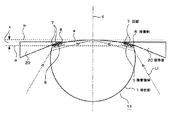
図8においては、球状部1と、円錐形状や角錐形状なる凸状部2を有するソリッドイマージョンレンズ11の一例の要部の拡大断面構成図を示す。図8に示すように、この例は球状部1を超半球状とする例で、その曲率半径をrとし、凸状部2の光軸cに沿う断面における傾斜部の対物面3に沿う面(破線bで示す)となす角度をθ、対物面3の半径をd、ソリッドイマージョンレンズの厚さをr(1+1/n)、凸状部2の対物面3から球状部1の縁部4までの高さをx、光軸から縁部4までの距離をyとし、ソリッドイマージョンレンズ1の使用波長での屈折率をnとする。図8において、破線aは球状部1の縁部4を横切る断面、破線Rは光軸cと直交する断面において半径がrとなる断面を示す。
Next, before describing the effects of the steps and recesses of the solid immersion lens according to the present invention, the bonding mode between the solid immersion lens and the holder will be described with reference to the drawings.
FIG. 8 shows an enlarged cross-sectional configuration diagram of a main part of an example of a
このとき、傾斜角度θと、対物面3から球状部3までの高さxの関係は、下記の式(1)及び式(2)から求められる。
tanθ=x/(y−d) ・・・・(1)
r2=y2+((r/n)−x)2 ・・・(2)
At this time, the relationship between the inclination angle θ and the height x from the object surface 3 to the spherical portion 3 can be obtained from the following equations (1) and (2).
tan θ = x / (y−d) (1)
r 2 = y 2 + ((r / n) −x) 2 (2)
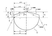
例えば、半径rを0.45mm、対物面3の半径dを20μm、レンズの屈折率nを2.075とした場合において、傾斜角度θを10度から30度まで変化させた場合の対物面3から球状部3の縁部4までの高さ、すなわち高低差xを求めた。
レンズの保持体は、その表面(光記録媒体と対向する面)が、レンズの対物面3からある程度のマージンをもって離間して接着される。このマージンとして、レンズ保持体表面と、レンズの対物面との高低差を50μmとすると、保持体とレンズとの接着領域の高さ(高低差)x´は、上記高低差xから50μm差し引いた値となり、接着領域の図8に示す断面における長さy´は、y´=x´/(sinθ)より求められる。この結果を以下の表1に示す。
For example, when the radius r is 0.45 mm, the radius d of the objective surface 3 is 20 μm, and the refractive index n of the lens is 2.075, the objective surface 3 when the tilt angle θ is changed from 10 degrees to 30 degrees. To the edge 4 of the spherical portion 3, that is, the height difference x was determined.
The surface of the lens holder (the surface facing the optical recording medium) is bonded with a certain margin from the objective surface 3 of the lens. As the margin, if the height difference between the lens holder surface and the objective surface of the lens is 50 μm, the height (height difference) x ′ of the adhesion region between the holder and the lens is subtracted by 50 μm from the height difference x. The length y ′ in the cross section shown in FIG. 8 of the adhesion region is obtained from y ′ = x ′ / (sin θ). The results are shown in Table 1 below.

この表1の結果から明らかなように、凸状部2の傾斜角度θが30度の場合は、対物面から球状部までの高低差を約250μm確保することができるが、傾斜角度が10度の場合は、対物面3から球状部1の縁部4までの高低差は約70μmしか確保することができなくなる。このことから明らかなように、傾斜角度が小さいほど、対物面3から球状部1の縁部4までの高低差xが小さくなり、また接着領域の高低差x´及び長さy´も小さくなってしまうことがわかる。
As is apparent from the results in Table 1, when the inclination angle θ of the
ソリッドイマージョンレンズは、その開口数NAが高いほど、すなわち、レーザの入射角度が大きいほど、また、ソリッドイマージョンレンズの半径rが小さいほど、屈折率nが大きいほど、凸状部2の傾斜角度θは小さくなるので、ソリッドイマージョンレンズの高NA化、小型軽量化によって、この対物面3から球状部1の縁部4までの高さが小さくなってしまうのは明らかである。
The solid immersion lens has a higher numerical aperture NA, that is, a larger incident angle of the laser, a smaller radius r of the solid immersion lens, and a larger refractive index n, and an inclination angle θ of the
図9及び図10にソリッドイマージョンレンズの各例の概略構成を示すように、このような凸状部2を有するソリッドイマージョンレンズでは、凸状部2の傾斜面の一部を利用して保持体20との接着領域5とし、光硬化性樹脂、熱硬化性樹脂等より成る接着剤6により保持体20と固着して保持している。保持体20の形状としては、例えばその平面形状は、対物面3を取り囲む円孔を有するドーナツ状等として、光軸に沿う断面形状は、対物面3に向かって鋭角が構成される三角形状とし得る。
ソリッドイマージョンレンズの凸状部の先端の対物面3の半径は、例えば数μmから数十μm程度であり、凸状部2の傾斜角度、すなわち対物面3との成す角度θは、10〜30度程度であるので、レンズの対物面3と保持体20の光記録媒体(図示せず)と対向する面との高低差xは、数十μmから数百μm程度である。
As shown in the schematic configuration of each example of the solid immersion lens in FIG. 9 and FIG. 10, in the solid immersion lens having such a
The radius of the objective surface 3 at the tip of the convex portion of the solid immersion lens is, for example, about several μm to several tens of μm, and the inclination angle of the
図9においては、角度θが20度程度の例、図10においては、角度θが10度程度の例を示す。図9及び図10において、図8と対応する部分には同一符号を付して重複説明を省略する。
上記表1の結果と、これら図9及び図10から明らかなように、凸状部2の傾斜角度θが小さくなると、接着面積が小さくなることがわかる。
すなわち、傾斜角度θが比較的大きい場合には、図9に示すように、対物面3から球状部1の縁部4までの高低差xが比較的大きく、接着領域5を確保することができる。一方、図10に示すように、円錐角度θが比較的小さい場合には、対物面3から球状部1の縁部4までの高低差xは比較的小さくなって、結果的に接着領域5の面積は、図9の例と比較して、明らかに小さくなってしまうことがわかる。
9 shows an example in which the angle θ is about 20 degrees, and FIG. 10 shows an example in which the angle θ is about 10 degrees. 9 and 10, the same reference numerals are given to the portions corresponding to those in FIG.
As is apparent from the results of Table 1 and FIGS. 9 and 10, it can be seen that the adhesion area decreases as the inclination angle θ of the
That is, when the inclination angle θ is relatively large, as shown in FIG. 9, the height difference x from the objective surface 3 to the edge 4 of the spherical portion 1 is relatively large, and the adhesion region 5 can be secured. . On the other hand, as shown in FIG. 10, when the cone angle θ is relatively small, the height difference x from the object surface 3 to the edge 4 of the spherical portion 1 is relatively small. It can be seen that the area is clearly smaller compared to the example of FIG.
更に、図10の例のように、凸状部2の傾斜角度θが小さく、対物面3と保持体20の光記録媒体との対向面との高低差が小さい場合、保持体20と光記録媒体との間隔も小さくなるが、光記録媒体と保持体20との傾きマージンをある程度以上に確保しようとすると、保持体20の大きさを抑える必要があり、接着面積が更に小となってしまう。
例えば、ソリッドイマージョンレンズの対物面3から保持体20の光記録媒体との対向面までの高低差を上述したように50μmとすると、上記表1に示すように、傾斜角度θが30度の場合は、接着領域の長さy´を約400μm確保することができるが、傾斜角度が10度の場合は、高低差x´が僅か20μm、長さy´を120μm程度しか確保することができなくなることがわかる。
このように、微小な領域に接着しようとすると、接着面積が小さいために、実用上非常に不安定な接着となってしまう。
Furthermore, as in the example of FIG. 10, when the inclination angle θ of the
For example, when the height difference from the objective surface 3 of the solid immersion lens to the surface of the
As described above, if an attempt is made to adhere to a minute region, since the adhesion area is small, adhesion becomes extremely unstable in practice.
このため、本発明においては、凸状部の少なくとも一部に、段差もしくは凹部を設ける構成とするものである。
先ず、凸状部の保持体との接着領域に凹部を設ける例について、図11〜図14を参照して説明する。
For this reason, in this invention, it is set as the structure which provides a level | step difference or a recessed part in at least one part of a convex-shaped part.
First, the example which provides a recessed part in the adhesion | attachment area | region with the holding body of a convex-shaped part is demonstrated with reference to FIGS.
図11においては、凸状部2を例えば円錐形状として、その円錐傾斜面の保持体20との接着領域5に、断面三角形状の凹部7を形成した例を示す。このように凹部7を設けることにより、接着領域5に微細な凹凸面を設けて、接着剤6との接着面積を大とすることができて、従来に比して十分強固な保持が可能となる。
凹部7の加工方法としては、上述したように、(株)日立製作所製の集束イオンビーム加工観察装置FB−2100(商品名)などのフォーカスイオンビーム加工装置によるフォーカスイオンビーム加工方法により形成することが好ましい。このように、フォーカスイオンビーム加工方法により形成することによって、凹部7の深さ等の形状を精度良く形成でき、破線矢印Liで示すソリッドイマージョンレンズ11への入射光への影響を回避することができる。図11において、図8と対応する部分には同一符号を付して重複説明を省略する。
In FIG. 11, the convex-shaped
As described above, the recess 7 is formed by a focused ion beam processing method using a focused ion beam processing apparatus such as the focused ion beam processing observation apparatus FB-2100 (trade name) manufactured by Hitachi, Ltd. Is preferred. In this way, by forming by the focused ion beam processing method, the shape such as the depth of the concave portion 7 can be formed with high accuracy, and the influence on the incident light to the
図12においては、凹部7を断面四角形状とした例を示す。この場合おいても同様に、凹部7を設けることによって、この接着領域5における接着面積を大とすることができ、ソリッドイマージョンレンズ11を保持体20に十分な強度をもって固着することが可能となる。
図11において、図10と対応する部分には同一符号を付して重複説明を省略する。
このように、凸状部2を、円錐形状、角錐形状又は曲面形状のうちいずれかの形状とすることによって、比較的簡易な形状で接着面積を確保し、安定な保持が可能なソリッドイマージョンレンズを提供することができる。
In FIG. 12, the example which made the recessed part 7 square cross section is shown. Also in this case, similarly, by providing the concave portion 7, the adhesion area in the adhesion region 5 can be increased, and the
In FIG. 11, parts corresponding to those in FIG.
As described above, by forming the
なお、ソリッドイマージョンレンズ11の形状としては、図11及び図12に示す例の他、球状部を半球状としてもよく、また例えば図13に示すように、対物面3が、半径r/nの一点鎖線gで示す球に略外接する形状となるような、前述の図6において説明した例と同様の形状であってもよい。更に、図14に示すように、凸状部2を曲面形状として、すなわち前述の図7において説明した例と同様の形状としてもよい。このように、図13及び14に示すように、接着領域5に凹部7を設けることによって、同様に十分な強度をもってソリッドイマージョンレンズ11を保持体20に固着することが可能となる。図13及び図14において、図11と対応する部分には同一符号を付して重複説明を省略する。
As the shape of the
上述したように、接着領域5の少なくとも一部に凹部7を設ける場合は、前述の図10において説明した例と比べて明らかに、凸状部2の凹部7による凹凸面積の加工分だけ、接着面積を大きくすることが可能となる。したがって、ソリッドイマージョンレンズを安定に保持することができるので、ソリッドイマージョンレンズを小型化しても、安定な保持が可能となり、光記録媒体等との相対的な走行の安定化を図ることができる。
特に、凸状部2の傾斜角度θを比較的小さくする場合、すなわち、ソリッドイマージョンレンズ11へのレーザ入射角θiを大として、開口数NAを大とする場合、または、ソリッドイマージョンレンズの屈折率nが大きい場合、更に、ソリッドイマージョンレンズの半径rが小さい場合においても、上述したように凹部を設けることによって、安定した保持が可能な接着面積を確保することができる。
As described above, in the case where the concave portion 7 is provided in at least a part of the bonding region 5, it is apparent that the bonding is performed by the processing of the concave and convex area by the concave portion 7 of the
In particular, when the inclination angle θ of the
次に、凸状部の一部に段差を設ける例について説明する。図15に示す例においては、凸状部2に設ける段差8として、ソリッドイマージョンレンズ11の光軸cに沿う断面において、光軸cに対し異なる角度をもって傾斜する2以上の傾斜面、すなわち図示の例では対物面3から順に第1の面9A、第2の面9Bより構成した例を示す。
このように、凸状部2の傾斜部分を、光軸に対し異なる角度をもって傾斜するいわば複数の傾斜角度に加工することにより、ソリッドイマージョンレンズ11の開口数を大とするために凸状部2の傾斜角度を光軸から大とする場合においても、レンズ保持体20との接着領域5における光軸からの傾斜角度を小とする傾斜面、この場合第2の面9Bを設けることによって、この傾斜面において、レンズ保持体20との接着面積を比較的大とすることができ、安定な保持が可能となる。
ただし、この場合第2の面9Bの傾斜角度を、ソリッドイマージョンレンズ11の入射光Liを遮ることがないように、入射角度θiを考慮して選定することが望ましい。
すなわち、対物面3の半径dにより、ソリッドイマージョンレンズ11の凸状部2の傾斜角度を、ソリッドイマージョンレンズ11の入射角度θiに対するマージンをもって形成することができる。つまり、このマージンを利用することにより、第1の面9Aより対物面3からの傾斜角度が大きい第2の面9Bを設けることができて、これにより傾斜部分の長さをより長くして、結果的に保持体20との接着面積を確保することができることとなる。
Next, an example in which a step is provided in a part of the convex portion will be described. In the example shown in FIG. 15, as the step 8 provided on the
In this way, the
However, in this case, it is desirable to select the inclination angle of the second surface 9B in consideration of the incident angle θi so as not to block the incident light Li of the
That is, the inclination angle of the
そして、この場合においても、凸状部の傾斜角度が比較的小さく、ソリッドイマージョンレンズへの入射光の入射角度が大きく、開口数NAを大とする場合、またソリッドイマージョンレンズの屈折率が大きい場合、ソリッドイマージョンレンズの半径が小さい場合においても、安定した接着面積を確保することが可能となる。
図15において、図11と対応する部分には同一符号を付して重複説明を省略する。
Even in this case, the inclination angle of the convex portion is relatively small, the incident angle of the incident light to the solid immersion lens is large, the numerical aperture NA is large, and the refractive index of the solid immersion lens is large. Even when the radius of the solid immersion lens is small, a stable bonding area can be secured.
In FIG. 15, parts corresponding to those in FIG.
次に、実施例1及び2として、入射光への影響を及ぼすことなく凹部又は段差を形成する例について説明する。
〔1〕実施例1
ソリッドイマージョンレンズとして、(株)オハラ製S−LAH79(商品名)の高屈折率ガラス材料を利用し、図16に概略構成を示すように、ソリッドイマージョンレンズ11の半径rを0.45mm、その厚さr(1+1/n)を0.667mmとし、その対物側の凸状部2を対物面3に対し傾斜角度20度の円錐形状として、実施例1のソリッドイマージョンレンズとして作製した。このとき、対物面3の半径dは20μmとした。
Next, as Examples 1 and 2, an example in which a recess or a step is formed without affecting incident light will be described.
[1] Example 1
As a solid immersion lens, a high refractive index glass material of S-LAH79 (trade name) manufactured by OHARA Co., Ltd. is used. As shown schematically in FIG. 16, the radius r of the
この例においては、対物面3から球状部1の縁部4までの高さxは、155.0μmであり、一方、対物面3から入射光Liの入射位置までの高さxiは、216.6μmであった。従って、このxとxiの差による61.6μmの部分について、フォーカスイオンビーム装置などの機械加工による切削によって、図11に示すような微細な凹部を形成し、ソリッドイマージョンレンズのレンズ保持体20と接着した。その結果、前述の図9に示すように、機械加工による切削により凹部を形成しない場合に比べて、接着強度が増加していることを確認した。
In this example, the height x from the objective surface 3 to the edge 4 of the spherical portion 1 is 155.0 μm, while the height xi from the objective surface 3 to the incident position of the incident light Li is 216.m. It was 6 μm. Accordingly, a fine recess as shown in FIG. 11 is formed in the 61.6 μm portion due to the difference between x and xi by machining such as a focus ion beam apparatus, and the
〔2〕実施例2
次に、実施例2について説明する。ソリッドイマージョンレンズとして、(株)オハラ製S−LAH79(商品名)の高屈折率ガラス材料を利用し、図17に示すように、ソリッドイマージョンレンズ11の半径rを0.45mm、その厚さr(1+1/n)を0.667mmとし、対物側の凸状部2の形状を対物面3に対し傾斜角度10度の円錐形状としたものを実施例2のソリッドイマージョンレンズとして作製した。このとき、対物面3の半径dは20μmで作製した。
[2] Example 2
Next, Example 2 will be described. As a solid immersion lens, a high refractive index glass material of S-LAH79 (trade name) manufactured by OHARA INC. Is used, and as shown in FIG. 17, the radius r of the
このとき、対物面3から球状部1の縁部4までの高さxは、71.6μmであり、一方、対物面3から入射光Liの入射位置までの高さxiは、130.0μmであった。従って、このxとxiの差による58.4μmの部分について、フォーカスイオンビーム装置による加工により図15に示す段差形状を形成し、ソリッドイマージョンレンズのレンズ保持体と接着した。その結果、このような段差を形成しない場合に比べて、接着強度が増加していることを確認した。
これらの実施例1及び2における入射角度θi、傾斜角度θ、縁部の高さx及びこの高さxと入射位置の高さxiとの差(xi−x)を下記の表2に示す。
At this time, the height x from the objective surface 3 to the edge 4 of the spherical portion 1 is 71.6 μm, while the height xi from the objective surface 3 to the incident position of the incident light Li is 130.0 μm. there were. Therefore, a stepped shape shown in FIG. 15 was formed by processing with a focus ion beam device at a portion of 58.4 μm due to the difference between x and xi, and was bonded to the lens holder of the solid immersion lens. As a result, it was confirmed that the adhesive strength was increased as compared with the case where such a step was not formed.
Table 2 below shows the incident angle θi, the inclination angle θ, the edge height x, and the difference (xi−x) between the height x and the incident position height xi in Examples 1 and 2.
このように、入射位置の高さxiと、対物面からレンズの縁部までの高低差xとを考慮して、接着領域に設ける凹部の深さを適切に選定することによって、入射光を遮ることなく接着領域を確保することができ、保持体への強固な接着が可能となる。 As described above, the incident light is blocked by appropriately selecting the depth of the concave portion provided in the adhesion region in consideration of the height xi of the incident position and the height difference x from the object surface to the edge of the lens. The adhesion region can be secured without any problem, and the strong adhesion to the holding body is possible.
以上説明したように、本発明のソリッドイマージョンレンズによれば、凸状部を設けることにより光記録媒体との傾きマージンを大とし、かつこの凸状部の一部に凹部もしくは段差部を設けることによって、ソリッドイマージョンレンズとレンズ保持体との接着面積を十分に確保することが可能となる。
そして本発明によれば、開口数の大なる集光レンズを実現する小型のソリッドイマージョンレンズを安定に保持することができ、したがって、光記録媒体に対する安定走行を図り、記録再生の安定性を高めることが可能となって、ニアフィールド記録再生方式を採用する光記録媒体との安定した記録再生システムを構築することができる。
また、本発明によるソリッドイマージョンレンズを用いることにより、集光レンズの小型軽量化を実現できることから、フォーカスサーボやトラッキングサーボやシーク時間等のサーボ特性の向上を図ることができ、光学ピックアップ装置および光記録再生装置の小型化、薄型化、高性能化を図ることが可能となる。
これらの結果、本発明によれば、ニアフィールド記録再生方式を採用してより光記録媒体の高記録密度化、大容量化を実現できることとなる。
As described above, according to the solid immersion lens of the present invention, by providing the convex portion, the inclination margin with the optical recording medium is increased, and a concave portion or a step portion is provided in a part of the convex portion. Thus, it is possible to secure a sufficient adhesion area between the solid immersion lens and the lens holder.
According to the present invention, it is possible to stably hold a small solid immersion lens that realizes a condensing lens having a large numerical aperture. Therefore, stable running with respect to an optical recording medium is achieved, and stability of recording and reproduction is improved. This makes it possible to construct a stable recording / reproducing system with an optical recording medium employing a near-field recording / reproducing method.
Further, by using the solid immersion lens according to the present invention, the condenser lens can be reduced in size and weight, so that servo characteristics such as focus servo, tracking servo, and seek time can be improved. The recording / reproducing apparatus can be reduced in size, thickness, and performance.
As a result, according to the present invention, it is possible to realize a higher recording density and a larger capacity of the optical recording medium by employing the near-field recording / reproducing method.
なお、本発明は、上述の各例に限定されるものではなく、例えば凸状部に設ける凹部の断面形状を波型、不規則形状とするとか、或いは段差として、曲率の異なる曲面を隣接させる構成とするなど、本発明構成を逸脱しない範囲において、種々の変形、変更が可能であり、またその他ソリッドイマージョンレンズの材料構成、保持体の形状等においても、種々の変形、変更が可能であることはいうまでもない。 The present invention is not limited to the above examples. For example, the cross-sectional shape of the concave portion provided in the convex portion is a corrugated shape, an irregular shape, or curved surfaces having different curvatures are adjacent to each other as a step. Various modifications and changes can be made without departing from the structure of the present invention, such as a configuration, and various modifications and changes can also be made in the material configuration of the solid immersion lens, the shape of the holding body, and the like. Needless to say.
1.球状部、2.凸状部、3.対物面、4.縁部、5.接着領域、6.接着剤、7.凹部、8.段差、9A.第1の面、9B.第2の面、10.光記録媒体、11.ソリッドイマージョンレンズ、12.光学レンズ、13.集光レンズ、14.第1のビームスプリッタ、15.第2のビームスプリッタ、16.2軸アクチュエータ、17.トラッキング用コイル、18.フォーカシング用コイル、20.保持体 1. 1. spherical part; 2. convex portion; Object plane, 4. Edge, 5. Bonding area, 6. 6. adhesive, Recess, 8. Step, 9A. First surface, 9B. Second surface, 10. 10. optical recording medium, Solid immersion lens, 12. Optical lens, 13. Condensing lens, 14. First beam splitter, 15. 16. second beam splitter, 16.2 axis actuator, Tracking coil, 18. Coil for focusing, 20. Holding body
Claims (10)
上記凸状部の少なくとも一部に、段差もしくは凹部が設けられて成る
ことを特徴とするソリッドイマージョンレンズ。 On the object side of the solid immersion lens, a convex part protruding toward the object surface is provided,
A solid immersion lens, wherein at least a part of the convex part is provided with a step or a concave part.
ことを特徴とする請求項1記載のソリッドイマージョンレンズ。 The solid immersion lens according to claim 1, wherein the concave portion is provided in at least a part of an adhesion region with a holding body that holds the solid immersion lens.
ことを特徴とする請求項1記載のソリッドイマージョンレンズ。 2. The solid immersion lens according to claim 1, wherein the step is constituted by two or more inclined surfaces inclined at different angles with respect to the optical axis in a cross section along the optical axis of the solid immersion lens.
ことを特徴とする請求項1記載のソリッドイマージョンレンズ。 2. The solid immersion lens according to claim 1, wherein the convex portion has a conical shape, a pyramid shape, or a curved surface shape.
ことを特徴とする請求項2記載のソリッドイマージョンレンズ。 The solid immersion lens according to claim 2, wherein the convex portion has any one of a conical shape, a pyramid shape, or a curved surface shape.
ことを特徴とする請求項3記載のソリッドイマージョンレンズ。 4. The solid immersion lens according to claim 3, wherein the convex portion has a conical shape, a pyramid shape, or a curved surface shape.
上記ソリッドイマージョンレンズの対物側に、集光部に向かって突出する凸状部が設けられ、
上記凸状部の少なくとも一部に段差もしくは凹部が設けられて成る
ことを特徴とする集光レンズ。 In a condensing lens composed of a solid immersion lens and an optical lens that is aligned with the optical axis of the solid immersion lens and disposed on the side opposite to the objective side,
On the object side of the solid immersion lens, a convex portion that protrudes toward the condensing portion is provided,
A condensing lens, wherein a step or a recess is provided on at least a part of the convex portion.
上記ソリッドイマージョンレンズの対物側に、集光部に向かって突出する凸状部が設けられ、
上記凸状部の少なくとも一部に段差もしくは凹部が設けられて成る
ことを特徴とする光学ピックアップ装置。 At least a light source, a solid immersion lens and an optical lens that are arranged in order from the object side with the optical axis aligned, and a condensing lens that converges light emitted from the light source to form a light spot. In the optical pickup device,
On the object side of the solid immersion lens, a convex portion that protrudes toward the condensing portion is provided,
An optical pickup device comprising a step or a recess provided in at least a part of the convex portion.
上記集光レンズは、少なくともその対物側にソリッドイマージョンレンズが配置され、
上記ソリッドイマージョンレンズの対物側に、集光部に向かって突出する凸状部が設けられ、
上記凸状部の少なくとも一部に段差もしくは凹部が設けられて成る
ことを特徴とする光記録再生装置。 An optical pickup device that performs recording and / or reproduction by condensing light at a recording position of the optical recording medium by a condensing lens, the focusing lens and the optical pickup device being arranged in a focusing direction of the optical recording medium and / or Alternatively, in an optical recording / reproducing apparatus provided with at least control drive means for controlling and driving in the tracking direction,
The condenser lens has a solid immersion lens disposed at least on its objective side,
On the object side of the solid immersion lens, a convex portion that protrudes toward the condensing portion is provided,
An optical recording / reproducing apparatus, wherein at least a part of the convex portion is provided with a step or a concave portion.
上記ソリッドイマージョンレンズの対物側に、集光部に向かって突出する凸状部を形成し、
上記凸状部の少なくとも一部に段差もしくは凹部をフォーカスイオンビーム加工方法により形成する
ことを特徴とするソリッドイマージョンレンズの形成方法。 In the method of forming a solid immersion lens,
On the object side of the solid immersion lens, a convex portion that protrudes toward the condensing portion is formed,
A method of forming a solid immersion lens, wherein a step or a recess is formed in at least a part of the convex portion by a focus ion beam processing method.
Priority Applications (4)
| Application Number | Priority Date | Filing Date | Title |
|---|---|---|---|
| JP2005045736A JP2006114196A (en) | 2004-09-14 | 2005-02-22 | Solid immersion lens, focusing lens using the same, optical pickup apparatus, optical recording and reproducing apparatus and method of manufacturing solid immersion lens |
| US11/205,075 US7551540B2 (en) | 2004-09-14 | 2005-08-17 | Solid immersion lens, focusing lens using solid immersion lens, optical pickup apparatus, optical recording reproducing apparatus and method of manufacturing solid immersion lens |
| TW094128213A TW200625294A (en) | 2004-09-14 | 2005-08-18 | Solid immersion lens, focusing lens using solid immersion lens, optical pickup apparatus, optical recording reproducing apparatus and method of manufacturing solid immersion lens |
| KR1020050084080A KR20060051148A (en) | 2004-09-14 | 2005-09-09 | Solid immersion lens, focusing lens using solid immersion lens, optical pickup apparatus, optical recording reproducing apparatus and method of manufacturing solid immersion lens |
Applications Claiming Priority (2)
| Application Number | Priority Date | Filing Date | Title |
|---|---|---|---|
| JP2004267397 | 2004-09-14 | ||
| JP2005045736A JP2006114196A (en) | 2004-09-14 | 2005-02-22 | Solid immersion lens, focusing lens using the same, optical pickup apparatus, optical recording and reproducing apparatus and method of manufacturing solid immersion lens |
Publications (2)
| Publication Number | Publication Date |
|---|---|
| JP2006114196A true JP2006114196A (en) | 2006-04-27 |
| JP2006114196A5 JP2006114196A5 (en) | 2008-02-14 |
Family
ID=36145113
Family Applications (1)
| Application Number | Title | Priority Date | Filing Date |
|---|---|---|---|
| JP2005045736A Abandoned JP2006114196A (en) | 2004-09-14 | 2005-02-22 | Solid immersion lens, focusing lens using the same, optical pickup apparatus, optical recording and reproducing apparatus and method of manufacturing solid immersion lens |
Country Status (4)
| Country | Link |
|---|---|
| US (1) | US7551540B2 (en) |
| JP (1) | JP2006114196A (en) |
| KR (1) | KR20060051148A (en) |
| TW (1) | TW200625294A (en) |
Families Citing this family (13)
| Publication number | Priority date | Publication date | Assignee | Title |
|---|---|---|---|---|
| US7324185B2 (en) | 2005-03-04 | 2008-01-29 | Asml Netherlands B.V. | Lithographic apparatus and device manufacturing method |
| US8248577B2 (en) | 2005-05-03 | 2012-08-21 | Asml Netherlands B.V. | Lithographic apparatus and device manufacturing method |
| EP1881520A4 (en) * | 2005-05-12 | 2010-06-02 | Nikon Corp | Projection optical system, exposure apparatus and exposure method |
| KR101504765B1 (en) | 2005-05-12 | 2015-03-30 | 가부시키가이샤 니콘 | Projection optical system, exposure apparatus and exposure method |
| CN102097111B (en) * | 2009-12-15 | 2012-12-19 | 建兴电子科技股份有限公司 | Tilt control method for near field optical disk drive |
| US8767199B2 (en) | 2010-10-15 | 2014-07-01 | Infrared Laboratories, Inc. | Inspection system utilizing solid immersion lenses |
| JPWO2012063484A1 (en) * | 2010-11-10 | 2014-05-12 | パナソニック株式会社 | Optical pickup, tilt angle detection method, optical information apparatus, and information processing apparatus |
| TWI673528B (en) | 2014-09-26 | 2019-10-01 | 日商濱松赫德尼古斯股份有限公司 | Solid state immersion lens holder and image acquisition device |
| CN106949383B (en) * | 2017-04-01 | 2023-03-21 | 安徽仁和光电科技有限公司 | Illumination system utilizing laser to induce fluorescence |
| DE102017217389A1 (en) * | 2017-09-29 | 2019-04-04 | Carl Zeiss Microscopy Gmbh | An optical lens for use in a media delivery device and lens, media delivery device and microscope |
| GB2579163A (en) * | 2018-09-10 | 2020-06-17 | Res & Innovation Uk | Lens assembly for super-resolution microscopy |
| WO2020150239A1 (en) * | 2019-01-14 | 2020-07-23 | University Of Washington | Apparatuses, systems and methods for solid immersion meniscus lenses |
| DE102020111715A1 (en) * | 2020-04-29 | 2021-11-04 | Carl Zeiss Microscopy Gmbh | IMMERSION LENS AND PROCEDURE FOR IMMERSION MICROSCOPY |
Family Cites Families (8)
| Publication number | Priority date | Publication date | Assignee | Title |
|---|---|---|---|---|
| US5125750A (en) * | 1991-03-14 | 1992-06-30 | The Board Of Trustees Of The Leland Stanford Junior University | Optical recording system employing a solid immersion lens |
| US5729393A (en) * | 1996-04-03 | 1998-03-17 | Digital Papyrus Corporation | Optical flying head with solid immersion lens having raised central surface facing medium |
| TW409248B (en) * | 1996-05-01 | 2000-10-21 | Terastor Corp | Flying head with solid immersion lens |
| US5936928A (en) * | 1996-10-01 | 1999-08-10 | Terastor Corporation | Multilayer media and use with flying head having solid immersion lens |
| EP0911653B1 (en) * | 1997-09-05 | 2006-07-19 | Osram Opto Semiconductors GmbH | Immersion system |
| US6671246B1 (en) * | 1999-04-28 | 2003-12-30 | Olympus Optical Co., Ltd. | Optical pickup |
| US6594086B1 (en) * | 2002-01-16 | 2003-07-15 | Optonics, Inc. (A Credence Company) | Bi-convex solid immersion lens |
| JP4577023B2 (en) | 2004-03-15 | 2010-11-10 | ソニー株式会社 | Solid immersion lens, condensing lens, optical pickup device, optical recording / reproducing device, and method for forming solid immersion lens |
-
2005
- 2005-02-22 JP JP2005045736A patent/JP2006114196A/en not_active Abandoned
- 2005-08-17 US US11/205,075 patent/US7551540B2/en not_active Expired - Fee Related
- 2005-08-18 TW TW094128213A patent/TW200625294A/en unknown
- 2005-09-09 KR KR1020050084080A patent/KR20060051148A/en not_active Application Discontinuation
Also Published As
| Publication number | Publication date |
|---|---|
| TW200625294A (en) | 2006-07-16 |
| US20060077788A1 (en) | 2006-04-13 |
| US7551540B2 (en) | 2009-06-23 |
| KR20060051148A (en) | 2006-05-19 |
Similar Documents
| Publication | Publication Date | Title |
|---|---|---|
| JP2006114196A (en) | Solid immersion lens, focusing lens using the same, optical pickup apparatus, optical recording and reproducing apparatus and method of manufacturing solid immersion lens | |
| JP4577023B2 (en) | Solid immersion lens, condensing lens, optical pickup device, optical recording / reproducing device, and method for forming solid immersion lens | |
| JP2006114195A (en) | Lens holding member, focusing lens using the same, optical pickup apparatus and optical recording and reproducing apparatus | |
| JP2003006912A (en) | Optical information recording and reproducing device | |
| CN100359578C (en) | Solid immersion lens and method of manufacturing same | |
| US20040145996A1 (en) | Optical lens, condenser lens, optical pickup, and optical recording/reproducing apparatus | |
| JP2001034998A (en) | Optical head and its manufacture | |
| JP2006209850A (en) | Tilt detecting method and regulating unit, optical pickup device, and optical recording reproducing device | |
| JP2006228289A (en) | Optical lens device, near-field condenser lens device, optical pickup device, and optical recording and reproducing device | |
| JP4367102B2 (en) | Optical lens, condenser lens, optical pickup device, and optical recording / reproducing device | |
| JP3791509B2 (en) | Optical reproducing apparatus and optical reproducing method | |
| JP2006120295A (en) | Solid immersion lens and condensing lens using same, optical pickup device, magnetooptical recording and reproducing device, and method for forming solid immersion lens | |
| JP2005302267A (en) | Solid immersion lens, condensing lens using the same, optical pickup device, optical recording and reproducing device and method of forming solid immersion lens | |
| JP2006012379A (en) | Solid immersion lens, condenser lens, optical pickup device, optical recording/reproducing device, and metod for manufacturing solid immersion lens | |
| JP2005310352A (en) | Solid immersion lens, condenser lens, optical pickup, optical recording and reproducing device, and method for forming solid immersion lens | |
| JP2006190400A (en) | Near field optical recording/playback method, optical pickup apparatus, and optical recording/playback apparatus | |
| JP2005302268A (en) | Solid immersion lens, condensing lens, optical pickup device and optical recording and reproducing device | |
| JPWO2002091370A1 (en) | Optical device and information recording and / or reproducing device using the same | |
| JP2006344262A (en) | Solid immersion lens, optical pickup, and optical recording/reproducing device | |
| JP2006268924A (en) | Solid immersion lens and condensing lens using it, optical pickup device, optical recording/reproducing device, and manufacturing method of solid immersion lens | |
| US20060023578A1 (en) | Optical lens, focusing lens, optical pickup device as well as optical recording and reproducing device | |
| JP2005302266A (en) | Solid immersion lens, condensing lens using the same, optical pickup device and optical recording and reproducing device | |
| JP4356655B2 (en) | Solid immersion lens, optical pickup device, and optical recording / reproducing device | |
| JP3961648B2 (en) | Optical system for optical information recording / reproducing head | |
| JP2006190420A (en) | Optical detection method, solid immersion lens, condenser lens, optical pickup apparatus and its control method, optical recording and reproducing apparatus, and optical recording and reproducing method |
Legal Events
| Date | Code | Title | Description |
|---|---|---|---|
| A521 | Written amendment |
Free format text: JAPANESE INTERMEDIATE CODE: A523 Effective date: 20071219 |
|
| A621 | Written request for application examination |
Free format text: JAPANESE INTERMEDIATE CODE: A621 Effective date: 20071219 |
|
| A762 | Written abandonment of application |
Free format text: JAPANESE INTERMEDIATE CODE: A762 Effective date: 20090820 |