JP2006106166A - Endoscopic device - Google Patents
Endoscopic device Download PDFInfo
- Publication number
- JP2006106166A JP2006106166A JP2004289898A JP2004289898A JP2006106166A JP 2006106166 A JP2006106166 A JP 2006106166A JP 2004289898 A JP2004289898 A JP 2004289898A JP 2004289898 A JP2004289898 A JP 2004289898A JP 2006106166 A JP2006106166 A JP 2006106166A
- Authority
- JP
- Japan
- Prior art keywords
- adapter
- electrical contact
- side electrical
- optical system
- prism
- Prior art date
- Legal status (The legal status is an assumption and is not a legal conclusion. Google has not performed a legal analysis and makes no representation as to the accuracy of the status listed.)
- Pending
Links
Images


Abstract
Description
本発明は、内視対象の管腔内に挿入される挿入部に、照明部が配された撮像アダプタが着脱可能とされた内視鏡装置に関する。 The present invention relates to an endoscope apparatus in which an imaging adapter in which an illumination unit is arranged is detachably attached to an insertion part that is inserted into a lumen of an endoscopic object.
工業用や医療用として使用されている内視鏡装置は、管腔内に挿入される長尺の挿入部を備えている。また、このような内視鏡装置においては、管腔内の観察対象を照明して観察や撮像を容易にするため、外部の光源からの出射光を光ファイバ等のライトガイドにより挿入部の先端に配された照明光学系まで導光するものが提案されている(例えば、特許文献1参照。)。
このように挿入部の側面から内視対象を観察する内視鏡の場合、挿入部の先端部に配された対物光学系は、光路を約90度曲げるためのプリズムを備えている。そして、プリズムの配設位置よりもアダプタの先端側から照明光を照射するために、ライトガイドがプリズムの裏面側を通過して配されている。
Endoscope apparatuses used for industrial use and medical use include a long insertion portion that is inserted into a lumen. In such an endoscope apparatus, in order to facilitate observation and imaging by illuminating the observation target in the lumen, the light emitted from an external light source is guided by a light guide such as an optical fiber to the tip of the insertion portion. There has been proposed one that guides light to an illumination optical system disposed in (see, for example, Patent Document 1).
Thus, in the case of an endoscope that observes the endoscopic object from the side surface of the insertion portion, the objective optical system disposed at the distal end portion of the insertion portion includes a prism for bending the optical path by about 90 degrees. And in order to irradiate illumination light from the front end side of an adapter rather than the arrangement | positioning position of a prism, the light guide is distribute | arranged and passed through the back surface side of a prism.
一方、近年では、発光ダイオード(以下、LEDと称する。)を有し、そのLEDの光を照射するための照明部を備える撮像アダプタを挿入部の先端に着脱自在とし、観察対象や用途に応じて互いに異なる光学系が予め用意された複数種類の撮像アダプタの中から最適のものを選択して交換使用を可能に構成された内視鏡装置も提案されている。
このような内視鏡の場合、照明部に電源供給するために、LEDと接続された電気配線と挿入部に配された配線とを接続するための電気接点を配する必要がある。
On the other hand, in recent years, an imaging adapter having a light emitting diode (hereinafter referred to as LED) and having an illumination unit for irradiating light from the LED is made detachable at the distal end of the insertion unit, depending on the observation object and application. There has also been proposed an endoscope apparatus that is configured such that an optimal one can be selected from a plurality of types of imaging adapters that have different optical systems prepared in advance and can be exchanged.
In the case of such an endoscope, in order to supply power to the illumination unit, it is necessary to provide an electrical contact for connecting the electrical wiring connected to the LED and the wiring arranged in the insertion unit.
しかしながら、特許文献1に記載の内視鏡のライトガイドのようにプリズムの裏面側に電気配線する場合には、電気接点がプリズムよりもさらにアダプタの径方向外方に位置してしまい、撮像アダプタの外径が大きくなってしまう可能性がある。
本発明は上記事情に鑑みて成されたものであり、対物光学系の大きさが変化しても着脱可能な撮像アダプタの大径化を抑えて観察可能な内視鏡装置を提供することを目的とする。 The present invention has been made in view of the above circumstances, and provides an endoscope apparatus that enables observation while suppressing an increase in diameter of a detachable imaging adapter even if the size of the objective optical system changes. Objective.
本発明は、上記課題を解決するため、以下の手段を採用する。
本発明に係る内視鏡装置は、照明部を有して、管腔内に挿入される挿入部の先端部に着脱可能な撮像アダプタを備える内視鏡装置であって、前記撮像アダプタが、前記挿入部に配された挿入部側電気接点と接続可能なアダプタ側電気接点と、可撓性を有して前記アダプタ側電気接点と前記照明部とを電気的に接続する電気配線部と、内視対象物と対峙する対物光学系とを備え、前記アダプタ側電気接点が、前記対物光学系の少なくとも一部よりも前記撮像アダプタの基端側に、かつ、前記アダプタ側電気接点の少なくとも一部が、前記対物光学系の少なくとも一部よりも前記撮像アダプタの中心軸線側に配されていることを特徴とする。
The present invention employs the following means in order to solve the above problems.
An endoscope apparatus according to the present invention is an endoscope apparatus that includes an illumination adapter and includes an imaging adapter that can be attached to and detached from a distal end portion of an insertion portion that is inserted into a lumen. An adapter-side electrical contact that can be connected to the insertion-portion-side electrical contact disposed in the insertion portion; an electrical wiring portion that has flexibility and electrically connects the adapter-side electrical contact and the illumination portion; An objective optical system facing the endoscopic object, wherein the adapter-side electrical contact is closer to the proximal end side of the imaging adapter than at least a part of the objective optical system and at least one of the adapter-side electrical contacts. The portion is arranged closer to the central axis of the imaging adapter than at least a part of the objective optical system.
この内視鏡装置は、対物光学系が大きくなっても、撮像アダプタの中心軸線に対して対物光学系とアダプタ側電気接点との重なり状態を調整することによって、対物光学系の大型化の割合よりも小さい範囲に撮像アダプタの大径化を抑えることができる。 Even if the objective optical system becomes large, this endoscope apparatus adjusts the overlapping state of the objective optical system and the adapter-side electrical contact with respect to the center axis of the imaging adapter, thereby increasing the size of the objective optical system. An increase in the diameter of the imaging adapter can be suppressed within a smaller range.
また、本発明に係る内視鏡装置は、前記内視鏡装置であって、前記対物光学系が、光路を変更するプリズムを備え、前記アダプタ側電気接点の最も前記撮像アダプタの中心軸線に近い位置が、前記プリズムの最も前記撮像アダプタの中心軸線から遠い位置よりも前記撮像アダプタの中心軸線側に配されていることを特徴とする。 The endoscope apparatus according to the present invention is the endoscope apparatus, wherein the objective optical system includes a prism that changes an optical path, and the adapter-side electrical contact is closest to the central axis of the imaging adapter. The position of the prism is arranged closer to the center axis of the imaging adapter than a position farthest from the center axis of the imaging adapter.
この内視鏡装置は、側視型の撮像アダプタが備えるプリズムが大型化しても、アダプタ外径を拡大することなく電気配線することができ、アダプタの大径化をより好適に抑えることができる。 In this endoscope apparatus, even if the prism included in the side-view imaging adapter is enlarged, electric wiring can be performed without increasing the adapter outer diameter, and the increase in the diameter of the adapter can be suppressed more suitably. .
また、本発明に係る内視鏡装置は、前記内視鏡装置であって、前記対物光学系の光路と、前記撮像アダプタの中心軸線とが略同一とされ、前記アダプタ側電気接点の最も前記光路に近い位置が、前記対物光学系の最も前記光路から遠い位置よりも前記光路側に配されていることを特徴とする。 The endoscope apparatus according to the present invention is the endoscope apparatus, wherein an optical path of the objective optical system and a central axis of the imaging adapter are substantially the same, and the most of the adapter-side electrical contacts are A position close to the optical path is arranged closer to the optical path than a position farthest from the optical path of the objective optical system.
この内視鏡装置は、直視型の撮像アダプタが有する対物光学系の一部が大型化しても、アダプタ外径を拡大することなく電気配線することができ、アダプタの大径化をより好適に抑えることができる。 This endoscope apparatus can be electrically wired without enlarging the outer diameter of the adapter even if a part of the objective optical system of the direct-viewing type imaging adapter is enlarged, and it is more preferable to increase the diameter of the adapter. Can be suppressed.
本発明によれば、対物光学系を大型化してもアダプタの大径化を極力抑えることができる。 According to the present invention, the increase in diameter of the adapter can be suppressed as much as possible even if the objective optical system is enlarged.
本発明に係る第1の実施形態について、図1から図5を参照して説明する。
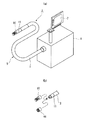
本実施形態に係る内視鏡装置1は、図1に示すように、長尺な軟性管2を有して管腔に挿入される挿入部5と、この挿入部5の基端が接続されたボックス状の装置本体部6とを備えている。
A first embodiment according to the present invention will be described with reference to FIGS.
As shown in FIG. 1, the
この内視鏡装置1は、挿入部5で捕えた画像信号を、軟性管2内部の信号線を通して装置本体部6に設置された信号処理回路(図示せず。)に出力し、信号処理回路で処理された信号を画像表示手段である液晶パネル7に映像として映し出すようになっている。尚、装置本体部6には、信号処理回路の他、バッテリ電源に接続された主電源回路(図示せず。)等が内蔵されている。
The
挿入部5は、LED照明ユニット(照明部)8を有して、管腔内に挿入される挿入部5の先端部に着脱可能なアダプタ(撮像アダプタ)10を備えている。
さらに詳しくは、軟性管2の先端側には金属等の硬質材料から成る連結プラグ11が設けられ、その連結プラグ11の先端部にアダプタ10が着脱可能に設けられている。
The
More specifically, a connecting
アダプタ10は所謂側視型のものであり、図2及び図3に示すように、さらに、略円筒状のアダプタ本体12と、挿入部5の連結プラグ11内に配された挿入部側電気接点13と接続可能なアダプタ側電気接点15と、可撓性を有してアダプタ側電気接点15とLED照明ユニット8とを電気的に接続する電気配線部16と、内視対象物と対峙する対物光学系17とを備えている。
アダプタ本体12には、対物光学系17を支持する第一の側口12Aと、LED照明ユニット8を支持する第二の側口12Bとが、同一の側面に開口して形成されている。
The
The adapter
対物光学系17は、内視対象物に対峙して第一の側口12Aに固定された第一レンズ18と、第一レンズ18で捉えた像を連結プラグ11内に支持されたCCDユニット20に結ぶように光路Cを略90度に曲げて、アダプタ本体12の中心軸線C1と一致させるためのプリズム21とを備えている。
The objective
プリズム21は、第一レンズ18から入射した光が中心軸線C1方向となるように光路を変更させる第一プリズム22と第二プリズム23とを備えた二面反射型とされている。
第一プリズム22は、中心軸線C1に対して図2の上側に配されており、第二プリズム23は、中心軸線C1に対して図2の下側に配されている。第一プリズム22と第二プリズム23とが互いに対向する面をそれぞれ第一面22Aと第二面23Aとしたとき、第一レンズ18から第一プリズム22に入射した光が、第一面22Aから出射するとともに、第二プリズム23の第二面23Aから入射し、図2において中心軸線C1よりも下側となる第二プリズム23の第三面23Bで反射した後、第二面23Aから出射して第一面22Aに至り、中心軸線C1方向に反射するように、光路Cに対して所定の角度で傾斜して配されている。
The
The
アダプタ側電気接点15は、図4に示すように、電気配線部16が中心部に接続された円板状の基板25と、基板に貼り付けられた異方性導電ゴム26とを供えている。
このアダプタ側電気接点15は、対物光学系17を構成するプリズム21よりもアダプタ10の基端側となるように、かつ、アダプタ側電気接点15の中心軸線C2がアダプタ本体12の中心軸線C1と平行となるように配されている。
アダプタ側電気接点15の最も中心軸線C1に近い最上位置15Aは、プリズム21の最も中心軸線C1から遠い最下位置21Aよりも中心軸線C1側に距離Δだけ上方に離間して配されている。
As shown in FIG. 4, the adapter-side
The adapter-side
The
ここで、異方性導電ゴム26は、シリコンゴム等の絶縁性のゴム素材に、ニッケル粒子や金メッキを施した金属粒子等の導電部材をドット状に埋設して構成されたものとされている。この異方性導電ゴム26は、弾性体であるゴム素材を厚さ方向に押圧すると、その圧縮変形によって高密度化した導電部材間の導電性が増し、それによって厚み方向の通電が許容されるようになる。この際、ゴム素材が絶縁部材であることから、ゴム素材の厚み方向以外の方向(例えば、周方向)については絶縁状態が維持される。
Here, the anisotropic
LED照明ユニット8は、対物光学系17よりもアダプタ10の先端側に配されており、図2及び図3に示すように、複数のLEDチップ27と、これらを載置する取付ベース28と、アダプタ本体12の第二の側口12Bに固定されるキャビティ部材30とを備えている。
各LEDチップ27は、図示しないLED電極にて電気配線部16と電気的に接続されている。
The
Each
電気配線部16は、光路Cと重ならないようにプリズム21及びLED照明ユニット8の裏面側となる、アダプタ本体12内に設けられた配線スペース31内に配されており、保守時にLED照明ユニット8を第二の側口12Bから取り出し可能な程度に弛んだ状態で収納されている。
The
この挿入部側電気接点13は、図4に示すように連結プラグ11の先端に配されており、図示しないLED電源と接続された電気供給配線32の先端に接続された導電部材33と、導電部材33を連結プラグ11に支持するために導電部材33を覆う絶縁部材35とを備えている。
導電部材33は、図5(a)(b)に示すように、アダプタ10を装着した際に、異方性導電ゴム26の基端面26Aを押圧可能な程度に連結プラグ11の先端面11Aよりも先端側に突出して配されている。
As shown in FIG. 4, the insertion portion side
As shown in FIGS. 5A and 5B, the
この内視鏡装置1によれば、アダプタ10を挿入部5に装着する際、導電部材33の先端が異方性導電ゴム26を押圧することによって、異方性導電ゴム26が押圧方向に導電状態となり、アダプタ側電気接点15と挿入部側電気接点13とを電気的に接続することができる。
その際、アダプタ側電気接点15の最上位置15Aを対物光学系17を構成するプリズム21の最下位置21Aよりも中心軸線C1側に配するので、プリズム21が大きくなっても、中心軸線C1に対してプリズム21とアダプタ側電気接点15との重なり状態を調整することができ、プリズム21の大型化の割合よりも小さい範囲にアダプタ10の大径化を好適に抑えることができる。
また、絶縁部材35と異方性導電ゴム26とが密着状態となるので、アダプタ10外部からアダプタ10内部の電気系統への漏水を好適に抑えることができる。
According to this
At this time, since the
Further, since the
次に、第2の実施形態について図6を参照しながら説明する。
なお、上述した第1の実施形態と同様の構成要素には同一符号を付すとともに説明を省略する。
第2の実施形態と第1の実施形態との異なる点は、本実施形態に係る内視鏡装置40のアダプタ41における配線スペース42が、図6(a)に示すように、LED照明ユニット8及びプリズム21の側面側に設けられているとした点である。
Next, a second embodiment will be described with reference to FIG.
In addition, the same code | symbol is attached | subjected to the component similar to 1st Embodiment mentioned above, and description is abbreviate | omitted.
The difference between the second embodiment and the first embodiment is that the
電気配線部16は、図6(b)に示すように、光路Cと重ならないように、アダプタ本体12の中心軸線C1よりも図6(b)において上側に配されている。
この内視鏡装置40によれば、第1の実施形態と同様の作用・効果を奏することができる。そして、プリズム21の形状に応じて、第1の実施形態に係るアダプタ10と使い分けることができる。
As shown in FIG. 6B, the
According to this
次に、第3の実施形態について図7を参照しながら説明する。
なお、上述した他の実施形態と同様の構成要素には同一符号を付すとともに説明を省略する。
第3の実施形態と第1の実施形態との異なる点は、本実施形態に係る内視鏡装置45のアダプタ46が、直視型とされている点である。
Next, a third embodiment will be described with reference to FIG.
In addition, the same code | symbol is attached | subjected to the component similar to other embodiment mentioned above, and description is abbreviate | omitted.
The difference between the third embodiment and the first embodiment is that the
アダプタ本体47は、略円筒状とされており、先端開口端47Aには、対物光学系48が備える第一レンズ18が固定されている。
対物光学系48は、アダプタ46が直視型であるため、第1の実施形態のようなプリズム21は備えておらず、第一レンズ18の基端側には対物レンズ群50が配されている。
The adapter
In the objective
対物光学系48の光路Cと、アダプタ本体47の中心軸線C1とは略同一とされており、アダプタ側電気接点15の中心軸線C2が、光路C及び中心軸線C1と略平行となるように配されている。
また、光路Cに最も近いアダプタ側電気接点15の外周側面位置15Bが、光路Cから最も遠い第一レンズ18のアダプタ側電気接点15側外周端18Aよりも光路C側となるように距離Lだけ離間して配されている。
LED照明ユニット51に係る複数のLEDチップ27は、第一レンズ18の周囲に配されている。
The optical path C of the objective
Further, the outer peripheral
The plurality of
この内視鏡装置45によれば、直視型のアダプタ46に係る対物光学系48の第一レンズ18を大型化しても、アダプタ46全体の大径化を好適に抑えることができる。
According to the
なお、本発明の技術範囲は上記実施の形態に限定されるものではなく、本発明の趣旨を逸脱しない範囲において種々の変更を加えることが可能である。
例えば、上記第1の実施形態では、アダプタ10をアダプタ本体12の中心軸線C1方向から見たとき、図8(a)に示すように、アダプタ側電気接点15の最上位置15Aが、プリズム21の最下位置21Aよりも上側となるように配されているが、図8(b)に示すように、電気配線部16とアダプタ側電気接点15との接続位置まで、プリズム21の最下位置21Aより上側に配しても構わない。この場合、電気配線部16の湾曲状態を調整することによって、上記実施形態と同様の作用・効果を得ることができる。
The technical scope of the present invention is not limited to the above embodiment, and various modifications can be made without departing from the spirit of the present invention.
For example, in the first embodiment, when the
また、電気配線部16を一つの基板55に離間して配したアダプタ側電気接点56を、図8(c)(d)のそれぞれに示すように、最上位置56Aが、プリズム21の最下位置21Aよりも上側となるように配したものとしても構わない。
さらに、図9(a)(b)に示すように、プリズム21の側面21Bよりも内側にアダプタ側電気接点15を配しても構わない。また、図9(c)(d)に示すように、プリズム21の側面21Bに対して、電気配線部16と基板55とが内側に重なるように配してもわない。
また、上記各ケースにおいて、アダプタ側電気接点15、56の全体がプリズム21の最下位置21Aよりも上側とされても構わない。
In addition, the adapter-side
Furthermore, as shown in FIGS. 9A and 9B, the adapter-side
Further, in each case described above, the entire adapter-side
また、図10に示すように、挿入部側電気接点60が、電気供給配線32と接続された基板25と、基板25の先端側に配された異方性導電ゴム26とを備え、アダプタ側電気接点61が、電気配線部16と接続されて基端がアダプタ本体12の基端面12Cよりも突出して配された導電部材33と、導電部材を覆う絶縁部材35とを備えているとしても構わない。
この場合、アダプタ62を挿入部63に装着する際、上記実施形態と同様の作用・効果を奏することができる。
As shown in FIG. 10, the insertion portion side
In this case, when the
また、内視対象物への出射光量を増やすために、図11(a)に示すように、第二の側口65Aを第一の側口12A側にも延びるように形成したアダプタ本体65に対し、LED照明ユニット66に係る複数のLEDチップ27の一部を、第一レンズ18の側面側に配してもよい。さらに、図11(b)に示すように、第一の側口12Aの周囲を第二の側口66Aが囲むようにアダプタ本体66を形成して第一レンズ18の基端側にLEDチップ27を配したLED照明ユニット68としても構わない。この場合、内視対象に対する照明ムラを減らすことができる。
Further, in order to increase the amount of light emitted to the endoscopic object, as shown in FIG. 11A, the adapter
また、光路Cとアダプタの中心軸線C1とが一致する場合だけでなく、ずれている場合であっても、同様の作用・効果を奏することができる。 Further, not only when the optical path C and the center axis C1 of the adapter coincide with each other but also when the optical path C and the center axis C1 are deviated, the same operation and effect can be achieved.
1、40、45 内視鏡装置
5、63 挿入部
8、51、66、68 LED照明ユニット(照明部)
10、41、46、62 アダプタ(撮像アダプタ)
13、60 挿入部側電気接点
15、56、61 アダプタ側電気接点
16 電気配線部
17、48 対物光学系
21 プリズム
C 光路
C1 中心軸線
1, 40, 45
10, 41, 46, 62 Adapter (imaging adapter)
13, 60 Insertion portion side
Claims (3)
前記撮像アダプタが、前記挿入部に配された挿入部側電気接点と接続可能なアダプタ側電気接点と、
可撓性を有して前記アダプタ側電気接点と前記照明部とを電気的に接続する電気配線部と、
内視対象物と対峙する対物光学系とを備え、
前記アダプタ側電気接点が、前記対物光学系の少なくとも一部よりも前記撮像アダプタの基端側に、かつ、前記アダプタ側電気接点の少なくとも一部が、前記対物光学系の少なくとも一部よりも前記撮像アダプタの中心軸線側に配されていることを特徴とする内視鏡装置。 An endoscope apparatus that includes an illumination adapter and includes an imaging adapter that can be attached to and detached from a distal end portion of an insertion portion that is inserted into a lumen.
The imaging adapter is an adapter-side electrical contact that can be connected to an insertion-unit-side electrical contact disposed in the insertion unit;
An electrical wiring portion having flexibility to electrically connect the adapter-side electrical contact and the illumination portion;
An objective optical system facing the endoscopic object,
The adapter side electrical contact is closer to the proximal end side of the imaging adapter than at least a part of the objective optical system, and at least a part of the adapter side electrical contact is more than the at least part of the objective optical system. An endoscope apparatus, characterized in that the endoscope apparatus is disposed on a central axis side of an imaging adapter.
前記アダプタ側電気接点の最も前記撮像アダプタの中心軸線に近い位置が、前記プリズムの最も前記撮像アダプタの中心軸線から遠い位置よりも前記撮像アダプタの中心軸線側に配されていることを特徴とする請求項1に記載の内視鏡装置。 The objective optical system includes a prism that changes an optical path,
The position of the adapter-side electrical contact closest to the center axis of the imaging adapter is arranged closer to the center axis of the imaging adapter than the position of the prism farthest from the center axis of the imaging adapter. The endoscope apparatus according to claim 1.
前記アダプタ側電気接点の最も前記光路に近い位置が、前記対物光学系の最も前記光路から遠い位置よりも前記光路側に配されていることを特徴とする請求項1に記載の内視鏡装置。
The optical path of the objective optical system and the central axis of the imaging adapter are substantially the same,
2. The endoscope apparatus according to claim 1, wherein a position of the adapter side electrical contact closest to the optical path is arranged closer to the optical path than a position farthest from the optical path of the objective optical system. .
Priority Applications (1)
| Application Number | Priority Date | Filing Date | Title |
|---|---|---|---|
| JP2004289898A JP2006106166A (en) | 2004-10-01 | 2004-10-01 | Endoscopic device |
Applications Claiming Priority (1)
| Application Number | Priority Date | Filing Date | Title |
|---|---|---|---|
| JP2004289898A JP2006106166A (en) | 2004-10-01 | 2004-10-01 | Endoscopic device |
Publications (2)
| Publication Number | Publication Date |
|---|---|
| JP2006106166A true JP2006106166A (en) | 2006-04-20 |
| JP2006106166A5 JP2006106166A5 (en) | 2007-11-08 |
Family
ID=36376005
Family Applications (1)
| Application Number | Title | Priority Date | Filing Date |
|---|---|---|---|
| JP2004289898A Pending JP2006106166A (en) | 2004-10-01 | 2004-10-01 | Endoscopic device |
Country Status (1)
| Country | Link |
|---|---|
| JP (1) | JP2006106166A (en) |
Cited By (5)
| Publication number | Priority date | Publication date | Assignee | Title |
|---|---|---|---|---|
| JP2007310214A (en) * | 2006-05-19 | 2007-11-29 | Olympus Corp | Insulating holder, adapter for endoscope, endoscope apparatus and endoscope system |
| JP2007312809A (en) * | 2006-05-23 | 2007-12-06 | Olympus Corp | Endoscope adapter, manufacturing method of endoscope adapter and endoscope apparatus |
| JP2009058807A (en) * | 2007-08-31 | 2009-03-19 | Olympus Medical Systems Corp | Imaging unit |
| JP2009294466A (en) * | 2008-06-05 | 2009-12-17 | Olympus Corp | Side-viewing adapter for endoscope and endoscope device |
| US8314835B2 (en) | 2009-01-23 | 2012-11-20 | Olympus Corporation | Endoscope adapter including light emitting diode, and adapter type endoscope |
Citations (3)
| Publication number | Priority date | Publication date | Assignee | Title |
|---|---|---|---|---|
| JPH03107220A (en) * | 1989-09-20 | 1991-05-07 | Nec Corp | Method and apparatus for adaptive conversion coding |
| JPH06222263A (en) * | 1993-01-22 | 1994-08-12 | Olympus Optical Co Ltd | Endoscopic objective lens |
| JPH10229965A (en) * | 1997-02-19 | 1998-09-02 | Asahi Optical Co Ltd | Endoscope |
-
2004
- 2004-10-01 JP JP2004289898A patent/JP2006106166A/en active Pending
Patent Citations (3)
| Publication number | Priority date | Publication date | Assignee | Title |
|---|---|---|---|---|
| JPH03107220A (en) * | 1989-09-20 | 1991-05-07 | Nec Corp | Method and apparatus for adaptive conversion coding |
| JPH06222263A (en) * | 1993-01-22 | 1994-08-12 | Olympus Optical Co Ltd | Endoscopic objective lens |
| JPH10229965A (en) * | 1997-02-19 | 1998-09-02 | Asahi Optical Co Ltd | Endoscope |
Cited By (6)
| Publication number | Priority date | Publication date | Assignee | Title |
|---|---|---|---|---|
| JP2007310214A (en) * | 2006-05-19 | 2007-11-29 | Olympus Corp | Insulating holder, adapter for endoscope, endoscope apparatus and endoscope system |
| JP2007312809A (en) * | 2006-05-23 | 2007-12-06 | Olympus Corp | Endoscope adapter, manufacturing method of endoscope adapter and endoscope apparatus |
| US8419616B2 (en) | 2007-08-20 | 2013-04-16 | Olympus Medical Systems Corp. | Image pickup device with a protection member and an optical reflection member |
| JP2009058807A (en) * | 2007-08-31 | 2009-03-19 | Olympus Medical Systems Corp | Imaging unit |
| JP2009294466A (en) * | 2008-06-05 | 2009-12-17 | Olympus Corp | Side-viewing adapter for endoscope and endoscope device |
| US8314835B2 (en) | 2009-01-23 | 2012-11-20 | Olympus Corporation | Endoscope adapter including light emitting diode, and adapter type endoscope |
Similar Documents
| Publication | Publication Date | Title |
|---|---|---|
| US7662093B2 (en) | Reduced size imaging device | |
| US7762950B2 (en) | Endoscope | |
| US8043211B2 (en) | Endoscope device with a heat removal portion | |
| JP5704878B2 (en) | Photoelectric conversion connector, optical transmission module, imaging device, and endoscope | |
| US7749160B2 (en) | Endoscope device | |
| CN103269645A (en) | Ultrasonic endoscope | |
| CN102802500A (en) | Connector system | |
| CN106886088B (en) | Endoscope with a detachable handle | |
| WO2011092900A1 (en) | Lighting unit, endoscope having the lighting unit, and lighting probe having the lighting unit and capable of being inserted through endoscope channel | |
| JP2005027851A (en) | Endoscope | |
| US20240115114A1 (en) | Illuminator circuit board assembly for an endoscope | |
| JP2006106166A (en) | Endoscopic device | |
| JP6041285B1 (en) | Videoscope connector for ultra-fine imaging unit | |
| JP2007014488A (en) | Endoscope | |
| US20200110257A1 (en) | Imaging unit and endoscope | |
| JP5738645B2 (en) | Endoscope | |
| KR101516318B1 (en) | Endoscopy lighting module improving light efficiency | |
| JP2019520108A (en) | Endoscope lighting circuit board assembly | |
| WO2017187621A1 (en) | Cable connection structure, imaging device, and endoscope | |
| JP5006125B2 (en) | Endoscope and endoscope optical adapter | |
| US20170325665A1 (en) | Illuminator Circuit Board Assembly for An Endoscope | |
| JP4689995B2 (en) | Endoscope device | |
| JP5361596B2 (en) | Adapter and endoscope | |
| JP4519494B2 (en) | Endoscope device | |
| JP2019216826A (en) | Inspection aid and inspection tool |
Legal Events
| Date | Code | Title | Description |
|---|---|---|---|
| A521 | Written amendment |
Free format text: JAPANESE INTERMEDIATE CODE: A523 Effective date: 20070925 |
|
| A621 | Written request for application examination |
Free format text: JAPANESE INTERMEDIATE CODE: A621 Effective date: 20070925 |
|
| A131 | Notification of reasons for refusal |
Free format text: JAPANESE INTERMEDIATE CODE: A131 Effective date: 20101109 |
|
| A521 | Written amendment |
Free format text: JAPANESE INTERMEDIATE CODE: A523 Effective date: 20110111 |
|
| A521 | Written amendment |
Free format text: JAPANESE INTERMEDIATE CODE: A821 Effective date: 20110112 |
|
| A02 | Decision of refusal |
Free format text: JAPANESE INTERMEDIATE CODE: A02 Effective date: 20110802 |