JP2006103403A - Floor sheet - Google Patents
Floor sheet Download PDFInfo
- Publication number
- JP2006103403A JP2006103403A JP2004289818A JP2004289818A JP2006103403A JP 2006103403 A JP2006103403 A JP 2006103403A JP 2004289818 A JP2004289818 A JP 2004289818A JP 2004289818 A JP2004289818 A JP 2004289818A JP 2006103403 A JP2006103403 A JP 2006103403A
- Authority
- JP
- Japan
- Prior art keywords
- sheet
- floor
- floor sheet
- sound
- intermediate member
- Prior art date
- Legal status (The legal status is an assumption and is not a legal conclusion. Google has not performed a legal analysis and makes no representation as to the accuracy of the status listed.)
- Pending
Links
Images


Classifications
-
- E—FIXED CONSTRUCTIONS
- E04—BUILDING
- E04C—STRUCTURAL ELEMENTS; BUILDING MATERIALS
- E04C2/00—Building elements of relatively thin form for the construction of parts of buildings, e.g. sheet materials, slabs, or panels
- E04C2/30—Building elements of relatively thin form for the construction of parts of buildings, e.g. sheet materials, slabs, or panels characterised by the shape or structure
- E04C2/34—Building elements of relatively thin form for the construction of parts of buildings, e.g. sheet materials, slabs, or panels characterised by the shape or structure composed of two or more spaced sheet-like parts
- E04C2/3405—Building elements of relatively thin form for the construction of parts of buildings, e.g. sheet materials, slabs, or panels characterised by the shape or structure composed of two or more spaced sheet-like parts spaced apart by profiled spacer sheets
- E04C2002/3411—Dimpled spacer sheets
- E04C2002/3427—Dimpled spacer sheets with conical dimples
Abstract
Description
本発明は、車両や家屋などの床に配設されるフロアシートに関するものである。 The present invention relates to a floor sheet disposed on a floor of a vehicle or a house.
一般に、家屋の室内のフロアシートとして、合板に木目調のフローリング部材を貼り付けてなるフロアシートがある(例えば、特許文献1参照)。このようなフロアシートは、車両用のフロアシートして使用されるカーペットに比べ、意匠性に富み、かつ、ウォッシャブルであるため、ミニバンなどの車両で適用されることが望まれている。 In general, as a floor sheet in a house, there is a floor sheet in which a wood-grained flooring member is attached to a plywood (see, for example, Patent Document 1). Such a floor sheet is rich in design and is washable compared to a carpet used as a vehicle floor sheet, and thus is desired to be applied to a vehicle such as a minivan.
しかしながら、従来のような家屋に用いるフロアシートは、吸音性向上およびその剛性を高めるために厚めに形成されているので、このように厚めに形成されたフロアシートをそのまま車室のフロアに敷くことは、車両の総重量が増加するため好ましくかった。 However, since the floor sheet used in a conventional house is formed thick in order to improve sound absorption and increase its rigidity, the floor sheet thus formed is laid on the floor of the passenger compartment as it is. Was preferable because the total weight of the vehicle increased.
そこで、本発明では、車両の総重量の増加を抑えることができるとともに、吸音性向上およびその剛性も高めることができるフロアシートを提供することを目的とする。 Therefore, an object of the present invention is to provide a floor sheet that can suppress an increase in the total weight of the vehicle, improve sound absorption, and increase its rigidity.
前記課題を解決する本発明のうち請求項1に記載のフロアシートは、複数の中空の凸部が形成された少なくとも一つの薄板からなる中間部材と、この中間部材を挟み込む二つのシート部材とを備えるハニカム構造体を含んで構成されることを特徴とする。
The floor sheet according to
請求項1に記載の発明によれば、中間部材と二つのシート部材によって内部に複数の空間が形成されたハニカム構造体は、その重量が小さく、かつ、剛性が高いという特性を持っているため、このようなハニカム構造体を備えたフロアシートを例えば車両のフロアに適用すると、車両の総重量を抑えることができる他、フロアシート自体の吸音性や剛性も高くすることができる。 According to the first aspect of the present invention, the honeycomb structure in which a plurality of spaces are formed by the intermediate member and the two sheet members has characteristics that the weight is small and the rigidity is high. When a floor sheet provided with such a honeycomb structure is applied to, for example, a vehicle floor, the total weight of the vehicle can be suppressed, and the sound absorption and rigidity of the floor sheet itself can be increased.
請求項2に記載の発明は、請求項1に記載のフロアシートであって、前記中間部材は、前記薄板を複数有し、各薄板に形成された複数の前記凸部が互いに当接されて構成されていることを特徴とする。 A second aspect of the present invention is the floor sheet according to the first aspect, wherein the intermediate member includes a plurality of the thin plates, and the plurality of convex portions formed on the thin plates are in contact with each other. It is configured.
請求項2に記載の発明によれば、凸部の高さを高くせずに、中間部材に形成される空間を大きくすることができるので、剛性が高められるとともに、衝撃吸収性や吸音性をも向上させることができる。 According to the second aspect of the present invention, since the space formed in the intermediate member can be increased without increasing the height of the convex portion, the rigidity is improved and the impact absorption and sound absorption properties are improved. Can also be improved.
請求項3に記載の発明は、請求項1または請求項2に記載のフロアシートであって、前記フロアシートの少なくとも一面側に、外部とハニカム構造体内の空間とに連通する連通孔を開けたことを特徴とする。
Invention of Claim 3 is the floor sheet of
ここで、「一面側に連通孔を開ける」とは、一面側のうちシート部材と薄板の板状部分とが重なり合う部分においては、これら両方の部材に連通孔を開けることをいい、一面側のうちシート部材と中空の凸部(シート部材側から見ると凹部となっている)とが重なり合う部分においては、シート部材のみに連通孔を開けることをいう。 Here, “opening a communication hole on one surface side” means that a communication hole is formed in both of the members on the one surface side where the sheet member and the plate-like portion of the thin plate overlap. Among them, in a portion where the sheet member and the hollow convex portion (which is a concave portion when viewed from the sheet member side) overlap, it means that a communication hole is opened only in the sheet member.
請求項3に記載の発明によれば、フロアシートの少なくとも一面側に連通孔が開けられているので、例えば、その一面側のシート部材が通気性を有さない部材であっても、そのシート部材側で発生する騒音を連通孔から取り込んでハニカム構造体内で良好に吸収することができる。 According to the invention described in claim 3, since the communication hole is formed on at least one surface side of the floor sheet, for example, even if the sheet member on the one surface side is a member having no air permeability, the sheet Noise generated on the member side can be taken in from the communication hole and absorbed well in the honeycomb structure.
請求項4に記載の発明は、請求項1〜請求項3のうちのいずれか1項に記載のフロアシートであって、前記連通孔が開けられたシート部材は、前記連通孔に開口する貫通孔を有した木材または樹脂からなる表面材を備えることを特徴とする。 Invention of Claim 4 is a floor sheet of any one of Claims 1-3, Comprising: The sheet | seat member by which the said communicating hole was opened is the penetration which opens to the said communicating hole A surface material made of wood or resin having holes is provided.
請求項4に記載の発明によれば、通常、通気性を有さない表面材に、シート部材の連通孔へ開口する貫通孔が開いているので、例えば、車室内の騒音を床材としてのハニカム構造体によって良好に吸収することができるとともに、その車の所有者が自分の好みにあった表面材を自由に選択して快適性を向上させることもできる。 According to the fourth aspect of the present invention, since the through-hole that opens to the communication hole of the seat member is normally opened in the surface material that does not have air permeability, for example, the noise in the vehicle interior is used as the floor material. It can be absorbed well by the honeycomb structure, and the car owner can freely select a surface material that suits his / her preference to improve comfort.
請求項1に記載の発明によれば、重量が小さく、かつ、剛性が高いという特性を持ったハニカム構造体をフロアシートの構成要素とするため、このようなフロアシートを例えば車両のフロアに適用すると、車両の総重量を抑えることができる他、フロアシート自体の吸音性や剛性も高くすることができる。 According to the first aspect of the present invention, a honeycomb structure having characteristics of low weight and high rigidity is used as a constituent element of the floor sheet. Therefore, such a floor sheet is applied to, for example, a vehicle floor. Then, the total weight of the vehicle can be suppressed, and the sound absorption and rigidity of the floor sheet itself can be increased.
請求項2に記載の発明によれば、凸部の高さを高くせずに、中間部材に形成される空間を大きくすることができるので、剛性が高められるとともに、衝撃吸収性や吸音性をも向上させることができる。 According to the second aspect of the present invention, since the space formed in the intermediate member can be increased without increasing the height of the convex portion, the rigidity is improved and the impact absorption and sound absorption properties are improved. Can also be improved.
請求項3に記載の発明によれば、フロアシートの少なくとも一面側に連通孔が開けられているので、例えば、その一面側のシート部材が通気性を有さない部材であっても、そのシート部材側で発生する騒音を連通孔から取り込んでハニカム構造体内で良好に吸収することができる。 According to the invention described in claim 3, since the communication hole is formed on at least one surface side of the floor sheet, for example, even if the sheet member on the one surface side is a member having no air permeability, the sheet Noise generated on the member side can be taken in from the communication hole and absorbed well in the honeycomb structure.
請求項4に記載の発明によれば、通常、通気性を有さない表面材に、シート部材の連通孔へ開口する貫通孔が開いているので、例えば、車室内の騒音を床材としてのハニカム構造体によって良好に吸収することができるとともに、その車の所有者が自分の好みにあった表面材を自由に選択して快適性を向上させることもできる。 According to the fourth aspect of the present invention, since the through-hole that opens to the communication hole of the seat member is normally opened in the surface material that does not have air permeability, for example, the noise in the vehicle interior is used as the floor material. It can be absorbed well by the honeycomb structure, and the car owner can freely select a surface material that suits his / her preference to improve comfort.
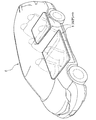
次に、本発明の実施形態について、適宜図面を参照しながら詳細に説明する。参照する図面において、図1は本実施形態に係るフロアシートが配設された車両を示す斜視図であり、図2は図1のフロアシートの詳細を示す分解斜視図である。また、図3は、図2のフロアシートを重ね合わせた状態を示す斜視図(a)と、図3(a)のA−A断面図(b)である。 Next, embodiments of the present invention will be described in detail with reference to the drawings as appropriate. In the drawings to be referred to, FIG. 1 is a perspective view showing a vehicle provided with a floor seat according to the present embodiment, and FIG. 2 is an exploded perspective view showing details of the floor seat of FIG. 3 is a perspective view (a) showing a state in which the floor sheets of FIG. 2 are overlaid, and a cross-sectional view taken along line AA of FIG. 3 (a).
図1に示すように、フロアシート1は、車両Cの床材として利用されている。具体的に、このフロアシート1は、図2に示すように、中間部材10と、この中間部材10を挟み込む二枚のシート部材20と、で主に構成されている。そして、二枚のシート部材20のうち上側のシート部材20には、フローリング部材(表面材)30が固着され、下側のシート部材20には、インシュレータ40が固着されている。なお、前記した中間部材10と、二枚のシート部材20とでハニカム構造体2が形成されるようになっている。
As shown in FIG. 1, the
図2に示すように、中間部材10は、上下に配設された二枚の薄板11,12で構成されている。この各薄板11,12には、互いに対応し合う複数の中空の凸部13,14が千鳥状に形成されており、これらの凸部13,14の先端同士は、それぞれ当接して固着されるようになっている(図3参照)。また、上側の薄板11の平板部11a(凸部13が形成されていない部分)には、上下に貫通する第1吸音孔(連通孔)H1が開けられている。さらに、この第1吸音孔H1は、薄板11の面に沿った一方向(凸部13が直線状に並ぶ方向)に所定のピッチαで形成されるとともに、前記した一方向とは直交する他方向に所定のピッチβで形成されている。
As shown in FIG. 2, the
シート部材20は、シート状に形成された通気性を有さない部材であり、前記した中間部材10の上下面に固着されている。そして、これら二枚のシート部材20のうち上側のシート部材20には、前記した第1吸音孔H1と同形状、同ピッチとなる第2吸音孔(連通孔)H2が第1吸音孔H1に対応するように開けられている。
The
なお、このシート部材20や前記した中間部材10の材料としては、ポリプロピレン(PP)を採用するのが望ましいが、本発明はこれに限らず、例えばエンプラ(エンジニアリング・プラスチック)やポリプロピレン以外の他のオレフィン系の樹脂などを採用してもよい。ここで、ポリプロピレン以外の他のオレフィン系樹脂としては、ポリエチレン、TPO(PPとゴム成分の混合物)などが挙げられる。また、エンプラとしては、ポリカーボネート、ポリアミド、変性ポリフェニレンエーテル、ポリエチレンテレフタレート、ポリブチレンテレフタレート、ポリアセタール、ポリフェニレンサルファイドなどが挙げられる。なお、このようなハニカム構造体2の製造方法としては、特開2000−326430号公報で開示した真空成形装置による製造方法や、射出成型による製造方法など、どのような製造方法を採用してもよい。
The material of the
フローリング部材30は、その表面30aに木目調などの模様が施された通気性を有さない部材であり、前記した上側のシート部材20に固着されている。そして、このフローリング部材30には、前記した第2吸音孔H2と同形状、同ピッチとなる第3吸音孔(貫通孔)H3が第2吸音孔H2に対応するように開けられている。
The
なお、前記した第1吸音孔H1、第2吸音孔H2および第3吸音孔H3(以下、これらの孔を単に「吸音孔H」ともいう)は、中間部材10、シート部材20およびフローリング部材30を重ね合わせて固着した後に、外部からハニカム構造体2内の空間へと同時に開けるのが望ましい。また、吸音孔Hの大きさや数は、任意であり、吸収したい騒音の大きさや周波数などに応じて適宜設定することができる。
The first sound absorbing hole H1, the second sound absorbing hole H2, and the third sound absorbing hole H3 (hereinafter, these holes are also simply referred to as “sound absorbing holes H”) are the
インシュレータ40は、吸音材であり、主に、路面側からの騒音(ロードノイズ)を吸音している。
The
次に、本実施形態に係るフロアシート1の吸音作用について説明する。
図3(b)に示すように、車室内で音が発生すると、その音は、吸音孔Hを介して中間部材10の空間(薄板11,12の平板部11a,12aと各凸部13,14の外周面とで形成される空間)内に入っていく。そして、このように中間部材10の空間内に入ってきた音は、各凸部13,14にぶつかって反射するときに、各凸部13,14を振動させるエネルギに変換されることで、徐々に弱められていき、この中間部材10によって吸音されることとなる。
Next, the sound absorbing action of the
As shown in FIG. 3 (b), when sound is generated in the passenger compartment, the sound is transmitted through the sound absorbing hole H to the space of the intermediate member 10 (the
以上によれば、本実施形態において、次のような効果を得ることができる。
通気性を有さない部材である薄板11、シート部材20およびフローリング部材30に吸音孔Hを開けるので、車室内の騒音をフロアシート1によって良好に吸収することができるとともに、その車の所有者が自分の好みにあったフローリング部材30を自由に選択して快適性を向上させることもできる。
According to the above, the following effects can be obtained in the present embodiment.
Since the sound absorbing hole H is opened in the
また、剛性が高く、吸音性を有し、かつ、軽量であるという特性を有するハニカム構造体2をフロアシート1の構成部材として使用したので、従来フロアに設けていた重いメルシート(遮音材)を設ける必要がなくなり、車両全体の軽量化を図ることができる。
さらに、内部が複雑な構造であるハニカム構造体2をフロアシート1の構成部材として利用することによって、そのフロアシート1に難燃性を持たせることができる。
Moreover, since the
Further, by using the
なお、本発明は、前記実施形態に限定されることなく、様々な形態で実施される。
本実施形態では、フロアシート1を車両のフロアに適用したが、本発明はこれに限定されず、例えば家屋の床に適用してもよい。また、中間部材10およびシート部材20の材質は、樹脂ではなく、例えば鉄などであってもよい。
In addition, this invention is implemented in various forms, without being limited to the said embodiment.
In the present embodiment, the
本実施形態では、上側の薄板11、上側のシート部材20およびフローリング部材30を貫通するように吸音孔Hを開けたが、本発明はこれに限定されず、例えば吸音孔を中空の凸部13とシート部材20との間に形成される空間に開口させる場合には、シート部材20とフローリング部材30のみを貫通するように吸音孔を開けてもよい。また、吸音孔は、本実施形態のように各板状の部材11,20,30の面に対して直交するように開ける必要はなく、例えば面に対して斜めになるように開けてもよい。
In the present embodiment, the sound absorbing hole H is opened so as to penetrate the upper
次に、前記実施形態に係るフロアシート1による吸音作用についての実施例(実験結果)を説明することとする。最初に、この実験の条件を示すこととする。
Next, an example (experimental result) about the sound absorbing action by the
〔条件〕
(1)中間部材10およびシート部材20の材質:ポリプロピレン(PP)
(2)インシュレータ40の材質:ウレタン
(3)吸音孔Hの直径:2mm
(4)吸音孔Hのピッチα:40mm
(5)吸音孔Hのピッチβ:30mm
(6)凸部13,14の高さ:5.5mm
(7)凸部13,14の先端面の直径:2mm
(8)凸部13,14の基端部の直径(開口部の直径):7mm
(9)凸部13,14のピッチ:11mm
(10)薄板11,12の厚さ:0.5mm
(11)シート部材20の厚さ:5.5mm
(12)フローリング部材30の厚さ:2mm
(13)インシュレータ40の厚さ:20mm
なお、吸音孔Hを前記したピッチα,βで形成することで、単位面積(1m2)当たりに形成される吸音孔Hの数は、8つとなっている。
〔conditions〕
(1) Material of the
(2) Material of insulator 40: Urethane (3) Diameter of sound absorbing hole H: 2 mm
(4) Pitch α of the sound absorbing holes H: 40 mm
(5) Pitch β of the sound absorbing holes H: 30 mm
(6) Height of
(7) Diameter of tip surfaces of
(8) Diameter of base end portion of
(9) Pitch of
(10) Thickness of the
(11) Thickness of the sheet member 20: 5.5 mm
(12) Thickness of the flooring member 30: 2 mm
(13) Thickness of the insulator 40: 20 mm
The number of sound absorbing holes H formed per unit area (1 m 2 ) is eight by forming the sound absorbing holes H at the pitches α and β.
〔実験結果〕
続いて、前記した条件となるフロアシート1による吸音性能について、図4を参照して説明する。
図4に示すように、このフロアシート1(吸音孔H有り)によれば、吸音孔Hがないフロアシート(吸音孔H以外は、前記実施形態のフロアシート1と同様の構成となるフロアシート)に比べ、周波数が約800〜4000Hz(ヘルツ)となる音に関する吸音性能が向上していることが分かる。特に、1000〜2000Hzの音に関しては、吸音孔Hがないフロアシートの吸音性能よりも、本実施例のフロアシート1の吸音性能の方が約20%以上も向上することが分かる。ここで、吸音性能は、音の吸収率(吸収された音のエネルギ/発生した音のエネルギ)のことを意味する。
〔Experimental result〕
Next, the sound absorption performance of the
As shown in FIG. 4, according to this floor sheet 1 (with sound absorbing holes H), a floor sheet having no sound absorbing holes H (a floor sheet having the same configuration as the
以上より、本実施例によれば、フロアシート1に所定の吸音孔Hを開けることで、所定の周波数の音を効率良く吸収することが確認された。
From the above, according to the present example, it was confirmed that by opening the predetermined sound absorption hole H in the
1 フロアシート
2 ハニカム構造体
10 中間部材
11,12 薄板
11a 平板部
13,14 凸部
20 シート部材
30 フローリング部材
40 インシュレータ
H 吸音孔
H1 第1吸音孔
H2 第2吸音孔
H3 第3吸音孔
DESCRIPTION OF
Claims (4)
前記中間部材は、前記薄板を複数有し、各薄板に形成された複数の前記凸部が互いに当接されて構成されていることを特徴とするフロアシート。 The floor sheet according to claim 1,
The intermediate member includes a plurality of the thin plates, and the plurality of convex portions formed on the thin plates are in contact with each other.
前記フロアシートの少なくとも一面側に、外部とハニカム構造体内の空間とに連通する連通孔を開けたことを特徴とするフロアシート。 The floor sheet according to claim 1 or 2,
A floor sheet, wherein a communication hole communicating with the outside and a space in the honeycomb structure is formed on at least one surface side of the floor sheet.
前記連通孔が開けられたシート部材は、前記連通孔に開口する貫通孔を有した木材または樹脂からなる表面材を備えることを特徴とするフロアシート。 It is a floor sheet given in any 1 paragraph of Claims 1-3,
The sheet member having the communication hole is provided with a surface material made of wood or resin having a through hole that opens to the communication hole.
Priority Applications (3)
| Application Number | Priority Date | Filing Date | Title |
|---|---|---|---|
| JP2004289818A JP2006103403A (en) | 2004-10-01 | 2004-10-01 | Floor sheet |
| US11/220,675 US20060080941A1 (en) | 2004-10-01 | 2005-09-08 | Floor sheet assembly |
| CNA2005101058744A CN1755044A (en) | 2004-10-01 | 2005-09-29 | Floor sheet assembly |
Applications Claiming Priority (1)
| Application Number | Priority Date | Filing Date | Title |
|---|---|---|---|
| JP2004289818A JP2006103403A (en) | 2004-10-01 | 2004-10-01 | Floor sheet |
Publications (1)
| Publication Number | Publication Date |
|---|---|
| JP2006103403A true JP2006103403A (en) | 2006-04-20 |
Family
ID=36179282
Family Applications (1)
| Application Number | Title | Priority Date | Filing Date |
|---|---|---|---|
| JP2004289818A Pending JP2006103403A (en) | 2004-10-01 | 2004-10-01 | Floor sheet |
Country Status (3)
| Country | Link |
|---|---|
| US (1) | US20060080941A1 (en) |
| JP (1) | JP2006103403A (en) |
| CN (1) | CN1755044A (en) |
Cited By (3)
| Publication number | Priority date | Publication date | Assignee | Title |
|---|---|---|---|---|
| JP2010243684A (en) * | 2009-04-03 | 2010-10-28 | Mitsubishi Electric Corp | Plate element |
| WO2018225706A1 (en) * | 2017-06-07 | 2018-12-13 | 株式会社 Ihi | Sound-absorbing panel and manufacturing method for same |
| CN109703483A (en) * | 2018-12-25 | 2019-05-03 | 芜湖尚唯汽车饰件有限公司 | Automobile collision preventing trim panel |
Families Citing this family (13)
| Publication number | Priority date | Publication date | Assignee | Title |
|---|---|---|---|---|
| US7210277B2 (en) | 2003-04-30 | 2007-05-01 | Lifetime Products, Inc. | Partition system |
| US7797885B2 (en) * | 2004-03-29 | 2010-09-21 | Lifetime Products, Inc. | Modular enclosure |
| US8091289B2 (en) * | 2004-03-29 | 2012-01-10 | Lifetime Products, Inc. | Floor for a modular enclosure |
| US7926227B2 (en) | 2004-03-29 | 2011-04-19 | Lifetime Products, Inc. | Modular enclosure with living hinges |
| US7658038B2 (en) | 2004-03-29 | 2010-02-09 | Lifetime Products, Inc. | System and method for constructing a modular enclosure |
| JP4302725B2 (en) * | 2006-04-27 | 2009-07-29 | 積水化成品工業株式会社 | Vehicle floor spacer |
| CH701771A2 (en) | 2009-09-15 | 2011-03-15 | Nico Ros | Closed-cell panel with a honeycomb structure made of two layers of textured film. |
| DE102010017321A1 (en) | 2010-06-10 | 2011-12-15 | International Automotive Components Group Gmbh | Cladding component for the interior of a motor vehicle |
| US10343380B2 (en) * | 2016-06-01 | 2019-07-09 | Ufp Technologies, Inc. | Trim component for a vehicle interior |
| CN106522510A (en) * | 2016-12-23 | 2017-03-22 | 重庆市万盛区万兴建筑材料有限公司 | Sound-insulation and vibration-prevention composite floor |
| CN109130343A (en) * | 2018-07-24 | 2019-01-04 | 佛山市南海区西樵桢英木业有限公司 | One kind having the wear-resisting glued board of good mechanical strength |
| CN111152514A (en) * | 2020-02-10 | 2020-05-15 | 南京旅游职业学院 | Sound absorption composite floor with buffer layer |
| CN115649301A (en) * | 2022-12-27 | 2023-01-31 | 质子汽车科技有限公司 | Vehicle with a steering wheel |
Family Cites Families (1)
| Publication number | Priority date | Publication date | Assignee | Title |
|---|---|---|---|---|
| DE3781836T2 (en) * | 1986-06-19 | 1993-04-29 | Daiken Trade & Industry | FLOATING FLOOR. |
-
2004
- 2004-10-01 JP JP2004289818A patent/JP2006103403A/en active Pending
-
2005
- 2005-09-08 US US11/220,675 patent/US20060080941A1/en not_active Abandoned
- 2005-09-29 CN CNA2005101058744A patent/CN1755044A/en active Pending
Cited By (6)
| Publication number | Priority date | Publication date | Assignee | Title |
|---|---|---|---|---|
| JP2010243684A (en) * | 2009-04-03 | 2010-10-28 | Mitsubishi Electric Corp | Plate element |
| WO2018225706A1 (en) * | 2017-06-07 | 2018-12-13 | 株式会社 Ihi | Sound-absorbing panel and manufacturing method for same |
| JPWO2018225706A1 (en) * | 2017-06-07 | 2020-04-16 | 株式会社Ihi | Sound absorbing panel and method for manufacturing sound absorbing panel |
| JP7113459B2 (en) | 2017-06-07 | 2022-08-05 | 株式会社Ihi | Acoustic panel and method for manufacturing acoustic panel |
| US11498306B2 (en) | 2017-06-07 | 2022-11-15 | Ihi Corporation | Sound-absorbing panel and manufacturing method for same |
| CN109703483A (en) * | 2018-12-25 | 2019-05-03 | 芜湖尚唯汽车饰件有限公司 | Automobile collision preventing trim panel |
Also Published As
| Publication number | Publication date |
|---|---|
| US20060080941A1 (en) | 2006-04-20 |
| CN1755044A (en) | 2006-04-05 |
Similar Documents
| Publication | Publication Date | Title |
|---|---|---|
| JP2006103403A (en) | Floor sheet | |
| US6720069B1 (en) | Sound absorbing structure | |
| JP6185859B2 (en) | Body panel structure | |
| JP6133796B2 (en) | Soundproof body and automotive insulator | |
| US8695758B2 (en) | Soundproof sheet for vehicles, manufacturing method thereof, and dash silencer for vehicles using soundproof sheet | |
| JP2009090845A (en) | Sound insulating material for vehicle | |
| JP6925082B2 (en) | Sound absorbing material for automobiles | |
| JPWO2020084802A1 (en) | Sound insulation material for automobiles | |
| JP4570675B2 (en) | floor mat | |
| JP2009096342A (en) | Vehicular interior material | |
| JP2006208859A (en) | Sound insulating material | |
| JP5512949B2 (en) | Vehicle sound absorber and vehicle sound absorbing structure using the same | |
| JP2006208949A (en) | Sound absorbing device | |
| JP2005280560A (en) | Lower leg part shock absorption pad with sound insulating property for vehicle | |
| US9707906B2 (en) | Soundproof material for vehicle and wire-harness assembly | |
| JP3564973B2 (en) | Carpet material | |
| JPH10329596A (en) | Floor carpet for automobile | |
| JP2005088706A (en) | Sound insulating material for vehicle | |
| JPWO2020136920A1 (en) | Damping material | |
| JP7315841B2 (en) | Structure | |
| JP4147146B2 (en) | Sound absorption floor | |
| KR20150001525U (en) | Using micro-perforated plate and the soundproofing | |
| JP7304122B2 (en) | Vehicle sound absorbing material | |
| JP5692032B2 (en) | Lower body structure | |
| JP2010095236A (en) | Vehicular interior trim member |
Legal Events
| Date | Code | Title | Description |
|---|---|---|---|
| A711 | Notification of change in applicant |
Free format text: JAPANESE INTERMEDIATE CODE: A711 Effective date: 20070706 |
|
| A977 | Report on retrieval |
Free format text: JAPANESE INTERMEDIATE CODE: A971007 Effective date: 20070719 |
|
| A521 | Written amendment |
Free format text: JAPANESE INTERMEDIATE CODE: A821 Effective date: 20070706 |
|
| A131 | Notification of reasons for refusal |
Free format text: JAPANESE INTERMEDIATE CODE: A131 Effective date: 20070829 |
|
| A521 | Written amendment |
Free format text: JAPANESE INTERMEDIATE CODE: A523 Effective date: 20071029 |
|
| A02 | Decision of refusal |
Free format text: JAPANESE INTERMEDIATE CODE: A02 Effective date: 20071205 |