JP2006097265A - Faucet metal fitting installing structure and installing method - Google Patents
Faucet metal fitting installing structure and installing method Download PDFInfo
- Publication number
- JP2006097265A JP2006097265A JP2004282076A JP2004282076A JP2006097265A JP 2006097265 A JP2006097265 A JP 2006097265A JP 2004282076 A JP2004282076 A JP 2004282076A JP 2004282076 A JP2004282076 A JP 2004282076A JP 2006097265 A JP2006097265 A JP 2006097265A
- Authority
- JP
- Japan
- Prior art keywords
- faucet
- fitting
- counter
- back surface
- faucet fitting
- Prior art date
- Legal status (The legal status is an assumption and is not a legal conclusion. Google has not performed a legal analysis and makes no representation as to the accuracy of the status listed.)
- Pending
Links
- 238000000034 method Methods 0.000 title claims abstract description 12
- 239000002184 metal Substances 0.000 title abstract description 21
- 239000000463 material Substances 0.000 claims abstract description 31
- XLYOFNOQVPJJNP-UHFFFAOYSA-N water Substances O XLYOFNOQVPJJNP-UHFFFAOYSA-N 0.000 claims description 66
- 238000005406 washing Methods 0.000 description 6
- 235000001537 Ribes X gardonianum Nutrition 0.000 description 5
- 235000001535 Ribes X utile Nutrition 0.000 description 5
- 235000016919 Ribes petraeum Nutrition 0.000 description 5
- 244000281247 Ribes rubrum Species 0.000 description 5
- 235000002355 Ribes spicatum Nutrition 0.000 description 5
- 238000005553 drilling Methods 0.000 description 3
- 238000005452 bending Methods 0.000 description 2
- 238000012856 packing Methods 0.000 description 2
- 239000002453 shampoo Substances 0.000 description 2
- 230000007246 mechanism Effects 0.000 description 1
Images



Landscapes
- Domestic Plumbing Installations (AREA)
Abstract
Description
本発明は、一般住戸で採用される浴室に設けられる水栓カウンタに取り付けられる水栓金具に係り、特にカウンタ前面のエプロン部に取設される水栓金具の取付構造に関する。また、本発明は、このような水栓金具の取付方法に関する。 The present invention relates to a faucet fitting attached to a faucet counter provided in a bathroom adopted in a general dwelling unit, and more particularly to an attachment structure of a faucet fitting attached to an apron portion on the front surface of the counter. Moreover, this invention relates to the attachment method of such a faucet metal fitting.
浴室の洗い場側に設けられ、カラン及びシャワーに所望の水量水温の水を給水給湯する浴室用の水栓は、洗い場の一壁面から突設するカウンタの前面エプロン部に、洗い場側に突出するように取り付けられるのが現在一般的である。これは、カウンタトップから上方に突出するように取り付けると、カウンタトップ上のシャンプー等の小物を置くスペースが狭くなるので、これを回避するためである。 The bathroom faucet, which is provided on the bathroom washroom side and supplies hot water with a desired amount of water temperature to the currant and shower, protrudes from the front apron of the counter protruding from one wall of the washroom to the washroom side. It is now common to be attached to. This is in order to avoid this because a space for placing small items such as shampoo on the counter top is narrowed if it is mounted so as to protrude upward from the counter top.
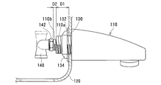
この水栓は、通常図11に示すように、前面エプロン部120に設けられた水栓110取付用の開口130に水栓110の後端を挿入し、パッキン132を介して締付リング134を締め込むことにより、カウンタの前面エプロン部120へ取り付けられる。そして、水栓110の後部にはL字形の配管ジョイント140がユニオンナット142によって取り付けられ、このジョイント140は混合水供給用のフレキホース(図示せず)と接続される(例えば、特許文献1参照。)。
In this faucet, as shown in FIG. 11, usually, the rear end of the
すなわち、水栓110後端には、締付リング134が螺挿される雄ねじ部110a、及びユニオンナット142が螺着される雄ねじ部110bの、径の異なる2種類の雄ねじ部が設けられるのが一般的である。
しかしながら、この構造では、水栓110の後端に、長さD1の雄ねじ部110aと長さD2の雄ねじ部110bの合計D1+D2の長さの接続部が必要となり、結果的にカウンタの奥行きも大きくなってしまうという問題点がある。また、締付リング134等の部品が必要となるためコストも高くなってしまう。
However, in this structure, a connecting portion having a total length D1 + D2 of the male screw portion 110a having the length D1 and the
本発明は、上述した事情を考慮してなされたもので、奥行きの短い水栓カウンタにも容易に水栓金具を取り付けることが可能な水栓金具の取付構造及び取付方法を提供することを目的とするものである。 The present invention has been made in consideration of the above-described circumstances, and an object of the present invention is to provide a faucet fitting mounting structure and a fitting method capable of easily attaching a faucet fitting to a faucet counter having a short depth. It is what.
本発明に係る水栓金具の取付構造は、上述した課題を解決するために、請求項1に記載したように、配管類を掩蔽する水栓カウンタの前面に露出して取設される水栓金具と、一端が上記水栓カウンタ背面に位置する壁面に固定され、他端が上記水栓金具裏面に当接して、上記水栓金具を所定の位置に支持する水栓支持材と、該水栓支持材の、上記水栓金具裏面に当接する部分の下端近傍に穿設されたボルト孔に螺合して、上記水栓金具裏面を押圧することにより上記水栓金具を上記水栓支持材に固着する固定ボルトとを備えるものである。 In order to solve the above-described problem, the faucet fitting mounting structure according to the present invention has a faucet that is exposed and installed on the front face of a faucet counter that covers piping. A faucet support material that has one end fixed to the wall surface located on the back surface of the faucet counter and the other end abutted against the back surface of the faucet fitting, and supports the faucet fitting in a predetermined position; The faucet fitting is screwed into a bolt hole drilled in the vicinity of the lower end of the portion of the faucet support that comes into contact with the back surface of the faucet fitting, and the faucet fitting is pressed against the faucet fitting by pressing the back face of the faucet fitting. And a fixing bolt that is fixed to the head.
前記水栓支持材は、より好適には、請求項2に記載したように、前記水栓金具の裏面に当接する部分において、前記水栓金具の裏面から延出する配管接続口を挿通可能とする開口を備え、上記水栓金具の裏面と上記配管接続口に螺合するエルボとに挟持されて上記水栓金具を仮固定することが望ましい。 More preferably, the faucet support member can be inserted through a pipe connection port extending from the back surface of the faucet fitting in a portion that contacts the back surface of the faucet fitting, as described in claim 2. It is desirable that the faucet fitting is temporarily fixed by being sandwiched between a back surface of the faucet fitting and an elbow screwed into the pipe connection port.
他方、上述した課題を解決するために、請求項3に係る水栓金具の取付方法は、配管類を掩蔽する水栓カウンタの前面に露出して取設される水栓金具の裏面から延出する配管接続口に、該配管接続口外周に螺刻された雄ねじの終端までエルボを螺進させて止水を完全にするステップと、一端が上記水栓カウンタ背面に位置する壁面に固定され、他端が上記水栓金具裏面に当接して、上記水栓金具を所定の位置に支持する水栓支持材の、上記水栓金具裏面に当接する部分の下端近傍に穿設されたボルト孔に、固定ボルトを螺嵌させ、該固定ボルトの螺進により上記水栓金具裏面を押圧することにより上記水栓金具を上記水栓支持材に固着する固着するステップとを備えるものである。
On the other hand, in order to solve the above-described problem, the faucet fitting mounting method according to
また、上述した課題を解決するために、請求項4に係る水栓金具の取付方法は、一端が配管類を掩蔽する水栓カウンタ背面に位置する壁面に固定された水栓支持材の他端に設けられた開口に、上記水栓カウンタの前面に露出して取設される水栓金具の裏面から延出する配管接続口を挿通するステップと、該配管接続口外周に螺刻された雄ねじの終端までエルボを螺進させて止水を完全にするとともに、上記支持材を水栓金具の裏面及び上記エルボで挟持することにより上記水栓金具を仮固定するステップと、上記水栓支持材の上記水栓金具裏面に当接する部分の下端近傍に穿設されたボルト孔に固定ボルトを螺嵌させ、該固定ボルトの螺進により上記水栓金具裏面を押圧することにより上記水栓金具を上記水栓支持材に固着するステップとを備えるものである。
Further, in order to solve the above-described problem, the faucet fitting mounting method according to
本発明に係る水栓金具の取付構造及び取付方法によれば、奥行きの短い水栓カウンタにも容易に水栓金具を取り付けることが可能となる。 According to the faucet fitting mounting structure and attachment method according to the present invention, it is possible to easily attach the faucet fitting to a faucet counter with a short depth.
本発明に係る水栓金具の取付構造及び取付方法の実施形態について、添付図面を参照して説明する。図1は、本発明に係る水栓金具取付構造を備えるシステムバス1の概略を示すものである。 DESCRIPTION OF EMBODIMENTS Embodiments of a faucet mounting structure and mounting method according to the present invention will be described with reference to the accompanying drawings. FIG. 1 shows an outline of a system bus 1 having a faucet fitting mounting structure according to the present invention.
システムバス1は、壁パネル6よりなる壁面により外部と区画され、洗い場2側の浴槽3に隣接する一の壁面には、洗い場水栓7周りの配管類を掩蔽する水栓カウンタとしてのアッパーカウンタ9が突設される。このアッパーカウンタ9は、その高さが、浴槽3天端と略同一に設定され、一端が浴槽3及びバスエプロン4に当接し、図示しない他端は、アッパーカウンタ9が取設された壁面と直交する壁面に当接している。アッパーカウンタ9の前面には、洗い場水栓7が取設される。吐水手段としてはこの他に、バス水栓5及びシャワー8を備える。シャワー8は、アッパーカウンタ9の底部から延出するシャワーホース82と、その先端に接続されたシャワーヘッド83を有する。このアッパーカウンタ9のカウンタトップは、シャンプーのボトル等の置き場として利用される。なお、本実施形態におけるアッパーカウンタ9は、本発明の水栓カウンタを構成する。
The system bath 1 is partitioned from the outside by a wall surface made of a
そして、アッパーカウンタ9の下方には、洗面器置き場とし使用されるロアーカウンタ10が取設される。
A
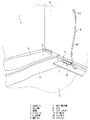
図2は、アッパーカウンタ9及びロアーカウンタ10を取り付ける前の、これらの支持材等を正面から見た図である。ここには、水栓本体70と、水栓本体を支持する水栓支持材11、アッパーカウンタ9を支持するアッパーカウンタ支持材20、ロアーカウンタを支持するロアーカウンタ支持材30、及びシャワー8を支持するシャワー支持材40とが取り付けられている。また、屋内給水管50及び屋内給湯管51の端末が壁パネル6を貫通して引き出されている。
FIG. 2 is a front view of these supporting members and the like before the
ロアーカウンタ10は棚状の平板であり、ロアーカウンタ支持材30は、ブラケット状に形成されてこの棚を支持する。
The
屋内給水管50及び屋内給湯管51は、それぞれ給水止水栓52及び給湯止水栓53が取り付けられた後、図示しないフレキシブル管を介して水栓本体70に接続される。そして、一旦水栓本体70内に取り込まれた水は、図示しないフレキシブル管を介してさらにシャワー支持材40に取り付けられたシャワーエルボ81に送出される。
The indoor
本実施形態の水栓本体70は、水平に横設された略円筒状の本体70aと、本体70aとアッパーカウンタ9とを接続する接続部70bとからなり、本体70aの中央下面からカラン71が突出し、カラン71の先端は水量調節ハンドル72になっている。本体70aの一端には温度調節ハンドル73が設けられ、他端には、送水先をカランまたはシャワーに切り替えるカランボタン74、シャワーボタン75が設けられる。
The
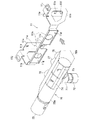
図3は、この水栓本体70を壁面に取り付けた状態を示す平面図である。水栓本体70は、同図に示すように、アッパーカウンタ9にではなく、水栓支持材11を介して壁面を構成する壁パネル6に取り付けられる。水栓支持材11に当接する水栓本体70裏面からは、給湯接続口76、給水接続口77及びシャワー接続口78が延出し、それぞれに給水エルボ61、給湯エルボ62及び水栓側シャワーエルボ63を介してフレキシブル管(図示せず)が接続され、給水接続口76は屋内給水管50の給水止水栓52、給湯接続口77は屋内給湯管51の給湯止水栓53へと接続される。また、シャワー接続口78は、水栓側シャワーエルボ63を介してフレキシブル管(図示せず)が接続され、シャワー支持材40に取り付けられたシャワーエルボ81に接続される。そして、シャワーエルボ81からシャワーホース82を経由してシャワーヘッド83が接続される。
FIG. 3 is a plan view showing a state in which the
このように、本発明に係る水栓金具の取付構造は、従来の水栓金具取付構造にある締付リングやこの締付リングに螺合する雄ねじ部がなく、給水接続口76等から直ちに給水エルボ61等を接続することができるので、アッパーカウンタ9の奥行きを、屋内給水管50等に取り付けられる給水止水栓52等の長さいっぱいまで小さくすることが可能となる。
Thus, the faucet fitting mounting structure according to the present invention does not have the fastening ring in the conventional faucet fitting mounting structure or the male thread portion that is screwed into the fastening ring, and immediately supplies water from the water
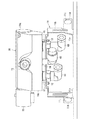
図4は、水栓本体70を壁面に取り付けた状態を示す縦断面図、言い換えれば、アッパーカウンタ9を取り付けた後に、図2のA−A方向から見た図である。同図に示すように、アッパーカウンタ9は、上面に位置するカウンタトップ91と、前面及び底面を掩蔽するカウンタエプロン92とから構成される。これらはアッパーカウンタ支持材20により壁パネル6に取り付けられる。カウンタトップ91の前面、すなわち、カウンタエプロン92の上部の一部には、図5に示すように、切欠きが設けられ、この位置に水栓支持材11の後述する水栓本体当接部11cが嵌合する。
FIG. 4 is a longitudinal sectional view showing a state in which the
水栓支持材11は、同図に示すように、金属製の板材を折曲して形成され、壁パネル当接部11a、突出部11b、水栓本体当接部11c、及びアッパーカウンタ当接部11dから構成される。壁パネル当接部11aには、アッパーカウンタ9の背面に位置する壁パネル6に当接してねじ止めできるよう、ねじ孔11e及び上下方向に長いばか孔11f,11fが穿設される。
As shown in the figure, the
この壁パネル当接部11aから90度折曲された突出部11bは、カウンタエプロン92側へ突出して、水栓本体70を支持する片持ち梁の役割を果たすものである。その中央部は、フレキシブル管を挿通させるため開口となっている。
The protruding
突出部11b上部には、外側へ90度折曲されたカウンタトップ91と当接するアッパーカウンタ当接部11dが設けられ、カウンタトップ92を固定するねじが挿通可能なねじ孔11jか穿設されている。
An upper
突出部11bから90度折曲され、水栓本体70の裏面に当接する水栓本体当接部11cには、水栓本体70の給水接続口76及び給湯接続口77を挿通可能とする開口11h,11h並びにシャワー接続口78を挿通可能とする欠切部11iが設けられる。また、水栓本体当接部11c両端下端近傍には、水栓本体70のアッパーカウンタ9への固着を確実ならしめる固定ボルト12を螺挿させるボルト孔11gが穿設される。この水栓本体当接部11cは、左右の突出部11b,11bを接続する役目も果たしている。
An
アッパーカウンタ支持材20も、金属製の板材を折曲して形成されたものであり、突出部20bを中心に、その壁パネル側に90度折曲された壁パネル当接部20aと、上側すなわちカウンタトップ91側に90度折曲されたカウンタトップ当接部20dと、下側すなわちカウンタエプロン92側に90度折曲されたカウンタエプロン当接部20cとから構成される。これら各部は、水栓支持材11のそれらと同等の機能を有し、壁パネル当接部20aにはねじ孔20e及びばか孔20f,20fが、カウンタトップ当接部20dにはねじ孔20jが、カウンタエプロン当接部20cにはねじ孔20kが穿設される。
The upper
本実施の形態に係る洗い場水栓7及びアッパーカウンタ9は上記のように構成されており、以下その取付手順について、図6に示すフローチャートを参照して説明する。
The
本実施の形態に係る水栓金具及びアッパーカウンタを壁パネルに取り付けるには、まず、水栓金具支持材11及びアッパーカウンタ支持材20の仮取り付けを行う(ステップS1)。これは、図5に示したように、壁パネル当接部11a,20aのばか孔11f,20fにのみドリリングねじ13を挿通し、壁パネルにねじ止めして行う。そして、カウンタトップ91をアッパーカウンタ支持材20の上に仮に載置する。
In order to attach the faucet fitting and the upper counter according to the present embodiment to the wall panel, first, the faucet
この段階では、まだ水栓支持材11も、アッパーカウンタ支持材20も上下方向にスライド可能であるので、水平器等を用いてカウンタトップ91のレベルを調整する(ステップS2)。レベル調整ができれば、図7に示すように、ねじ孔11e,20eにドリリングねじ13を挿通し、壁パネル6にねじ止めする。これにより、水栓支持材11及びアッパーカウンタ支持材20は所望の位置に本固定される(ステップS3)。
At this stage, both the
次に、シャワー支持材40を所定の位置に固定し、これにシャワーエルボ81を取り付ける(ステップS4)、続いて、水栓本体70を水栓支持材11に仮固定する(ステップS5)。それには、まず、図8に示すように、水栓本体70裏面の給水接続口76、給湯接続口77、及びシャワー接続口78を、それぞれ水栓支持材11の開口11h,11h及び欠切部11iに挿通する。
Next, the
そして、図9に示すように、給水エルボ60、給湯エルボ61、水栓側シャワーエルボ62を、それぞれ給水接続口76、給湯接続口77、及びシャワー接続口78に螺刻された雄ねじの終端に至るまで螺進させる。これにより、各エルボ内のパッキンが潰れて完全に止水される。しかしこの時点では、水栓本体70裏面と水栓支持材11の水栓本体当接部11cとは未だ固着しておらず、水栓本体70は、図10に示すように、正面がやや下方に垂れ下がった状態に留まり、がたつきもある。なぜなら、ここで完全に固着するように設定すると、各エルボを給水接続口76、給湯接続口77、及びシャワー接続口78に螺進させていって停止したとき、それが、各エルボが雄ねじの終端に至ったことによるのか、或いは、水栓本体70が水栓支持材11に固着したことによるのか判断できず、止水が完全か否かを確認できなくなるからである。
Then, as shown in FIG. 9, the
これに続いて、水栓本体70の本固定を行う(ステップS6)。これは、水栓支持材11の水栓本体当接部11c両端部下端近傍のボルト孔70gに螺着された固定ボルト12を螺進させることにより行う。これにより、水栓本体70の下部は、図10に示したように、螺進する固定ボルト12に押し出されるので、水栓本体70の正面は徐々に上方へと持ち上げられて、垂れ下がりが解除されるとともに、水栓支持材11に固着される。
Following this, the
このように、従来の取付構造では、口径の大きい締付リング及びこれに螺合する雄ねじ部により行われていた水栓金具の水栓カウンタへの固着が、本発明に係る取付構造によれば、極小さな固定ボルト12及びこれに螺合するボルト孔11gにより行われるので、固定ボルト12のボルトヘッドが給水エルボ60等よりも壁パネル6側へ突出することはなく、水栓カウンタの奥行きを小さくすることが可能となる。
Thus, in the conventional mounting structure, the fixing of the faucet fitting to the faucet counter, which has been performed by the tightening ring having a large diameter and the male screw portion screwed to the fastening ring, is performed according to the mounting structure according to the present invention. The bolt head of the fixing
また、本発明に係る取付構造では、給水接続口76等と給水エルボ60等との接続と、水栓本体70の水栓支持材11への固着とが、別々の機構により別途独立に行われるので、接続口周りの止水の完成と水栓本体70の固着の完了とを混同することなく、それぞれを確実にすることができる。
Further, in the mounting structure according to the present invention, the connection between the water
このように、水栓本体70が水栓支持材11に固着されれば、続いて、アッパーカウンタ9内部の配管類の接続を行う(ステップS7)。これは、給水止水栓52と給水エルボ60、給湯止水栓53と給湯エルボ61、水栓側シャワーエルボ62とシャワーエルボ81とを、それぞれフレキシブル管を用いて接続する。
Thus, if the faucet
こうして、支持材及び内部の処理が完了すると、カウンタトップ91及びカウンタエプロン92の取り付けを行う(ステップS8)。これは、座金を伴ったねじをねじ孔20j及び20kに挿通させて、カウンタトップ及びカウンタエプロンをねじ止めして行われる。
Thus, when the support material and the internal processing are completed, the counter top 91 and the
以上に説明した実施態様は説明のためのものであり、本発明の範囲を制限するものではない。従って、当業者であればこれらの各要素もしくは全要素をこれと均等なものによって置換した実施態様を採用することが可能であるが、これらの実施態様も本発明の範囲に含まれる。 The embodiments described above are for illustrative purposes and do not limit the scope of the invention. Accordingly, those skilled in the art can employ embodiments in which each or all of these elements are replaced by equivalents thereof, and these embodiments are also included in the scope of the present invention.
例えば、水栓本体の形状は本実施形態のものに限られず、シャワーが接続されていなくてもよい。また、水栓カウンタの高さは、浴槽の高さと略同一である必要はなく、ロアーカウンタを持たないシステムバスにおいても採用することができる。 For example, the shape of the faucet body is not limited to that of the present embodiment, and a shower may not be connected. Further, the height of the faucet counter need not be substantially the same as the height of the bathtub, and can be employed in a system bus having no lower counter.
1 システムバス
2 洗い場
3 浴槽
4 バスエプロン
5 バス水栓
6 壁パネル
7 洗い場水栓
8 シャワー
9 アッパーカウンタ
10 ロアーカウンタ
11 水栓支持材
11a 壁パネル当接部
11b 突出部
11c 水栓本体当接部
11d アッパーカウンタ当接部
11e,11j ねじ孔
11f ばか孔
11g ボルト孔
11h 開口
11i 欠切部
12 固定ボルト
13 ドリリングねじ
20 アッパーカウンタ支持材
20a 壁パネル当接部
20b 突出部
20c カウンタエプロロン当接部
20d カウンタ天板タ当接部
20e,20j
20k ねじ孔
20f ばか孔
30 ロアーカウンタ支持材
40 シャワー支持材
50 屋内給水管
51 屋内給湯管
52 給水止水栓
53 給湯止水栓
60 給水エルボ
61 給湯エルボ
62 水栓側シャワーエルボ
70 水栓本体
70a 本体
70b 接続部
71 カラン
72 水量調節ハンドル
73 温度調節ハンドル
74 カランボタン
75 シャワーボタン
76 給水接続口
77 給湯接続口
78 シャワー接続口
81 シャワーエルボ
82 シャワーホース
83 シャワーヘッド
91 カウンタトップ
92 カウンタエプロン
DESCRIPTION OF SYMBOLS 1 System bath 2
Claims (4)
一端が上記水栓カウンタ背面に位置する壁面に固定され、他端が上記水栓金具裏面に当接して、上記水栓金具を所定の位置に支持する水栓支持材と、
該水栓支持材の、上記水栓金具裏面に当接する部分の下端近傍に穿設されたボルト孔に螺合して、上記水栓金具裏面を押圧することにより上記水栓金具を上記水栓支持材に固着する固定ボルトと、
を備えることを特徴とする水栓金具の取付構造。 A faucet fitting that is exposed and installed on the front of the faucet counter that covers the piping,
A faucet support material that has one end fixed to the wall surface located on the back surface of the faucet counter and the other end abutted against the back surface of the faucet fitting, and supports the faucet fitting in a predetermined position;
The faucet bracket is screwed into a bolt hole formed in the vicinity of the lower end of the portion of the faucet support that is in contact with the back surface of the faucet bracket, and the faucet bracket is pressed against the faucet by pressing the back surface of the faucet bracket. A fixing bolt to be fixed to the support material;
A faucet fitting mounting structure characterized by comprising:
一端が上記水栓カウンタ背面に位置する壁面に固定され、他端が上記水栓金具裏面に当接して、上記水栓金具を所定の位置に支持する水栓支持材の、上記水栓金具裏面に当接する部分の下端近傍に穿設されたボルト孔に、固定ボルトを螺嵌させ、該固定ボルトの螺進により上記水栓金具裏面を押圧することにより上記水栓金具を上記水栓支持材に固着する固着するステップと、
を備えることを特徴とする水栓金具の取付方法。 The elbow is screwed into the pipe connection port extending from the back of the faucet fitting that is exposed and installed on the front of the faucet counter that covers the piping to the end of the male screw threaded around the pipe connection port. Letting the water stop completely,
The faucet fitting back surface of a faucet support material that has one end fixed to the wall surface located on the back face of the faucet counter and the other end abutted against the back face of the faucet fitting and supporting the faucet fitting in a predetermined position. A fixing bolt is screwed into a bolt hole drilled in the vicinity of the lower end of the portion that comes into contact with the stopper, and the faucet fitting is attached to the faucet support material by pressing the back surface of the faucet fitting by the screwing of the fixing bolt. An adhering step for adhering to,
A faucet fitting mounting method characterized by comprising:
該配管接続口外周に螺刻された雄ねじの終端までエルボを螺進させて止水を完全にするとともに、上記支持材を水栓金具の裏面及び上記エルボで挟持することにより上記水栓金具を仮固定するステップと、
上記水栓支持材の上記水栓金具裏面に当接する部分の下端近傍に穿設されたボルト孔に固定ボルトを螺嵌させ、該固定ボルトの螺進により上記水栓金具裏面を押圧することにより上記水栓金具を上記水栓支持材に固着するステップと、
を備えることを特徴とする水栓金具の取付方法。 A faucet fitting that is exposed on the front face of the faucet counter and is installed in the opening provided at the other end of the faucet support member that is fixed to the wall surface located on the rear face of the faucet counter that covers the piping. Inserting a pipe connection port extending from the back surface of
The elbow is screwed up to the end of the male screw threaded on the outer periphery of the pipe connection port to completely stop the water, and the support member is clamped by the back surface of the faucet fitting and the elbow. A temporary fixing step;
A fixing bolt is screwed into a bolt hole drilled in the vicinity of the lower end of the portion of the faucet support material that comes into contact with the back surface of the faucet fitting, and the back surface of the faucet fitting is pressed by screwing the fixing bolt. Fixing the faucet fitting to the faucet support;
A faucet fitting mounting method characterized by comprising:
Priority Applications (1)
| Application Number | Priority Date | Filing Date | Title |
|---|---|---|---|
| JP2004282076A JP2006097265A (en) | 2004-09-28 | 2004-09-28 | Faucet metal fitting installing structure and installing method |
Applications Claiming Priority (1)
| Application Number | Priority Date | Filing Date | Title |
|---|---|---|---|
| JP2004282076A JP2006097265A (en) | 2004-09-28 | 2004-09-28 | Faucet metal fitting installing structure and installing method |
Publications (1)
| Publication Number | Publication Date |
|---|---|
| JP2006097265A true JP2006097265A (en) | 2006-04-13 |
Family
ID=36237342
Family Applications (1)
| Application Number | Title | Priority Date | Filing Date |
|---|---|---|---|
| JP2004282076A Pending JP2006097265A (en) | 2004-09-28 | 2004-09-28 | Faucet metal fitting installing structure and installing method |
Country Status (1)
| Country | Link |
|---|---|
| JP (1) | JP2006097265A (en) |
Cited By (4)
| Publication number | Priority date | Publication date | Assignee | Title |
|---|---|---|---|---|
| JP2008029432A (en) * | 2006-07-26 | 2008-02-14 | Matsushita Denko Bath & Life Kk | Piping structure in bathroom counter |
| JP2008138396A (en) * | 2006-11-30 | 2008-06-19 | Kvk Corp | Cover faucet |
| JP2010007292A (en) * | 2008-06-25 | 2010-01-14 | Panasonic Electric Works Bath & Life Co Ltd | Faucet device |
| JP2010189887A (en) * | 2009-02-17 | 2010-09-02 | Toto Ltd | Faucet attachment structure |
Citations (4)
| Publication number | Priority date | Publication date | Assignee | Title |
|---|---|---|---|---|
| JPH0318272U (en) * | 1989-06-30 | 1991-02-22 | ||
| JPH0679862U (en) * | 1993-04-23 | 1994-11-08 | サンウエーブ工業株式会社 | Faucet mounting structure |
| JPH08246523A (en) * | 1995-03-07 | 1996-09-24 | Matsushita Electric Works Ltd | Faucet mounting structure |
| JPH101986A (en) * | 1996-06-13 | 1998-01-06 | Inax Corp | Mounting structure of mixing faucet with wall |
-
2004
- 2004-09-28 JP JP2004282076A patent/JP2006097265A/en active Pending
Patent Citations (4)
| Publication number | Priority date | Publication date | Assignee | Title |
|---|---|---|---|---|
| JPH0318272U (en) * | 1989-06-30 | 1991-02-22 | ||
| JPH0679862U (en) * | 1993-04-23 | 1994-11-08 | サンウエーブ工業株式会社 | Faucet mounting structure |
| JPH08246523A (en) * | 1995-03-07 | 1996-09-24 | Matsushita Electric Works Ltd | Faucet mounting structure |
| JPH101986A (en) * | 1996-06-13 | 1998-01-06 | Inax Corp | Mounting structure of mixing faucet with wall |
Cited By (4)
| Publication number | Priority date | Publication date | Assignee | Title |
|---|---|---|---|---|
| JP2008029432A (en) * | 2006-07-26 | 2008-02-14 | Matsushita Denko Bath & Life Kk | Piping structure in bathroom counter |
| JP2008138396A (en) * | 2006-11-30 | 2008-06-19 | Kvk Corp | Cover faucet |
| JP2010007292A (en) * | 2008-06-25 | 2010-01-14 | Panasonic Electric Works Bath & Life Co Ltd | Faucet device |
| JP2010189887A (en) * | 2009-02-17 | 2010-09-02 | Toto Ltd | Faucet attachment structure |
Similar Documents
| Publication | Publication Date | Title |
|---|---|---|
| WO2020102550A1 (en) | Top-mount faucet | |
| JP4644260B2 (en) | Faucet mounting structure | |
| JP2008231888A (en) | Wall faucet fixing structure | |
| US7490376B2 (en) | Drain outlet with integral clamp for use with a plumbing fixture | |
| JP3947347B2 (en) | Faucet mounting mechanism | |
| JPH0640689Y2 (en) | Mounting device for faucets, etc. | |
| JP2754310B2 (en) | How to connect hand tubing supply pipes | |
| JP2001280549A (en) | Pipe fittings | |
| JP2006265832A (en) | Faucet elbow fixture to unit bath | |
| JPH1151495A (en) | Fittings for connecting pipes for bathrooms | |
| KR200390670Y1 (en) | An Integrated Adaptor for Pipe | |
| JP4640229B2 (en) | Unit bathroom | |
| JPH0674864B2 (en) | Joint fixing structure for joint storage box | |
| JP2012046956A (en) | Faucet | |
| JPH07300884A (en) | Faucet joint and wall mounting method of faucet joint | |
| JP2006207165A (en) | Mounting structure of mixing faucet | |
| JPH087186Y2 (en) | Pipe fitting device for water purifier construction | |
| JP7457451B2 (en) | Pipe material | |
| JPH11336144A (en) | Faucet mounting device | |
| JP3319803B2 (en) | Connection structure of wall faucet | |
| KR200282511Y1 (en) | A device which fixes hot or cold water's distributing pipe in a sink | |
| JPH101986A (en) | Mounting structure of mixing faucet with wall | |
| JP2024071128A (en) | Joint Fixing Device | |
| JP2001070190A (en) | Counter mounting structure | |
| JP2002242248A (en) | Flush faucet |
Legal Events
| Date | Code | Title | Description |
|---|---|---|---|
| A621 | Written request for application examination |
Free format text: JAPANESE INTERMEDIATE CODE: A621 Effective date: 20070605 |
|
| A977 | Report on retrieval |
Free format text: JAPANESE INTERMEDIATE CODE: A971007 Effective date: 20100405 |
|
| A131 | Notification of reasons for refusal |
Effective date: 20100518 Free format text: JAPANESE INTERMEDIATE CODE: A131 |
|
| A02 | Decision of refusal |
Free format text: JAPANESE INTERMEDIATE CODE: A02 Effective date: 20100928 |