JP2006096334A - Shift operation device for bicycle - Google Patents

Shift operation device for bicycle Download PDF

Info

Publication number
JP2006096334A
JP2006096334A JP2005272131A JP2005272131A JP2006096334A JP 2006096334 A JP2006096334 A JP 2006096334A JP 2005272131 A JP2005272131 A JP 2005272131A JP 2005272131 A JP2005272131 A JP 2005272131A JP 2006096334 A JP2006096334 A JP 2006096334A
Authority
JP
Japan
Prior art keywords
shift
shift operation
bicycle
operation member
operating
Prior art date
Legal status (The legal status is an assumption and is not a legal conclusion. Google has not performed a legal analysis and makes no representation as to the accuracy of the status listed.)
Pending
Application number
JP2005272131A
Other languages
Japanese (ja)
Inventor
Kenji Ose
憲治 尾瀬
Current Assignee (The listed assignees may be inaccurate. Google has not performed a legal analysis and makes no representation or warranty as to the accuracy of the list.)
Shimano Inc
Original Assignee
Shimano Inc
Priority date (The priority date is an assumption and is not a legal conclusion. Google has not performed a legal analysis and makes no representation as to the accuracy of the date listed.)
Filing date
Publication date
Family has litigation
First worldwide family litigation filed litigation Critical https://patents.darts-ip.com/?family=35160025&utm_source=google_patent&utm_medium=platform_link&utm_campaign=public_patent_search&patent=JP2006096334(A) "Global patent litigation dataset” by Darts-ip is licensed under a Creative Commons Attribution 4.0 International License.
Application filed by Shimano Inc filed Critical Shimano Inc
Publication of JP2006096334A publication Critical patent/JP2006096334A/en
Pending legal-status Critical Current

Links

Images

Classifications

    • BPERFORMING OPERATIONS; TRANSPORTING
    • B62LAND VEHICLES FOR TRAVELLING OTHERWISE THAN ON RAILS
    • B62MRIDER PROPULSION OF WHEELED VEHICLES OR SLEDGES; POWERED PROPULSION OF SLEDGES OR SINGLE-TRACK CYCLES; TRANSMISSIONS SPECIALLY ADAPTED FOR SUCH VEHICLES
    • B62M25/00Actuators for gearing speed-change mechanisms specially adapted for cycles
    • B62M25/02Actuators for gearing speed-change mechanisms specially adapted for cycles with mechanical transmitting systems, e.g. cables, levers
    • B62M25/04Actuators for gearing speed-change mechanisms specially adapted for cycles with mechanical transmitting systems, e.g. cables, levers hand actuated
    • YGENERAL TAGGING OF NEW TECHNOLOGICAL DEVELOPMENTS; GENERAL TAGGING OF CROSS-SECTIONAL TECHNOLOGIES SPANNING OVER SEVERAL SECTIONS OF THE IPC; TECHNICAL SUBJECTS COVERED BY FORMER USPC CROSS-REFERENCE ART COLLECTIONS [XRACs] AND DIGESTS
    • Y10TECHNICAL SUBJECTS COVERED BY FORMER USPC
    • Y10TTECHNICAL SUBJECTS COVERED BY FORMER US CLASSIFICATION
    • Y10T74/00Machine element or mechanism
    • Y10T74/20Control lever and linkage systems
    • Y10T74/20396Hand operated
    • Y10T74/20402Flexible transmitter [e.g., Bowden cable]
    • Y10T74/2042Flexible transmitter [e.g., Bowden cable] and hand operator
    • Y10T74/20438Single rotatable lever [e.g., for bicycle brake or derailleur]

Abstract

<P>PROBLEM TO BE SOLVED: To provide a shift operation device for a bicycle with good operability. <P>SOLUTION: A first shift member 60 is connected to a first rotation shaft so as to rotate around a first rotation center line X and is moved along a first shift surface P<SB>1</SB>perpendicular to the first rotation center line. A second shift operation member 62 is connected to a second rotation shaft so as to rotate around a second rotation center line Y and is moved along a second shift surface P<SB>2</SB>perpendicular to the second rotation center line Y and crossing to the first shift surface P<SB>1</SB>with an angle of 30° or smaller. A shift control mechanism 26 is constituted so as to control a speed change gear for the bicycle and is functionally connected to the first and second shift operation members. <P>COPYRIGHT: (C)2006,JPO&NCIPI

Description

本発明は、自転車用シフト操作装置、特に、非平行で、非垂直な旋回中心線の回りに移動して自転車用変速機を作動させるシフト操作レバーを備える自転車用シフト操作装置に関する。   The present invention relates to a bicycle shift operation device, and more particularly to a bicycle shift operation device including a shift operation lever that moves around a non-parallel and non-vertical turning center line to operate a bicycle transmission.

自転車に乗ることは、移動の手段であるととともに、レクレーションの形態としてもますます人気が高まっている。また、自転車に乗ることは、プロ、アマを問わず、競技スポーツとしても人気が高い。レクレーション、移動、競技の用途に関わらず、自転車産業において、種々の自転車部品は常に改良が続けられている。詳細には、自転車用シフト機構すなわちシフト操作装置は、長くにわたって設計し直されてきた。   Riding a bicycle is not only a means of movement, but also an increasingly popular form of recreation. Bicycling is a popular sport for both professionals and amateurs. Regardless of recreational, mobile or competition applications, various bicycle components are constantly being improved in the bicycle industry. Specifically, bicycle shift mechanisms or shift operating devices have long been redesigned.

自転車用シフト機構は自転車用変速機のパーツである。自転車用変速機は、一般に、フロント及びリアディレーラを複数のフロント及びリアスプロケットにわたって横方向にそれぞれ移動させるよう設計されたフロント及びリアシフト機構を備える。フロント及びリアスプロケットは、通常、ライダーからのペダリングの力を、チェーンを介してリアホイールに伝えるようにフロントクランク及びリアホイールにそれぞれ連結されている。そして、フロント及びリアスプロケット上のチェーンの位置に応じてギア比の変更を行うことができる。
特開2003−205884号公報
A bicycle shift mechanism is a part of a bicycle transmission. Bicycle transmissions typically include a front and rear shift mechanism designed to move the front and rear derailleurs laterally across a plurality of front and rear sprockets, respectively. The front and rear sprockets are normally connected to the front crank and the rear wheel, respectively, so that pedaling force from the rider is transmitted to the rear wheel via the chain. The gear ratio can be changed according to the position of the chain on the front and rear sprockets.
JP 2003-205884 A

従来、シフト機構は、コントロールケーブルのインナーワイヤを巻き取り、巻き戻すように回動する一以上のレバーを備えるものが利用されている。また、回転するハンドグリップも、コントロールケーブルのインナーワイヤを巻き取り、解放するために利用されている。多段変速自転車には、一般に2つのシフト機構が備えられている。一般には、一方のシフト機構がフロントシフト機構であり、他方のシフト機構がリアシフト機構である。それぞれのシフト機構には、通常、インナーワーヤを有する1本のシフトケーブルが連結されている。フロント及びリアシフト機構のワイヤはフロント及びリアディレーラに連結され、これにより、チェーンを複数のフロント及びリアスプロケットにわたってシフトさせる。これらの従来のシフト機構はよく機能するものの、特にシフトレバーの移動に関してより無理のない人間工学的なシフト装置が求められている。   Conventionally, a shift mechanism that includes one or more levers that rotate so as to wind up and rewind an inner wire of a control cable is used. A rotating handgrip is also used to wind up and release the inner wire of the control cable. A multi-speed bicycle is generally provided with two shift mechanisms. In general, one shift mechanism is a front shift mechanism, and the other shift mechanism is a rear shift mechanism. Normally, one shift cable having an inner wire is connected to each shift mechanism. The front and rear shift mechanism wires are connected to the front and rear derailleurs, thereby shifting the chain across a plurality of front and rear sprockets. Although these conventional shift mechanisms function well, there is a need for an ergonomic shift device that is more comfortable with respect to movement of the shift lever in particular.

以上の観点から、従来技術における上述の問題点を克服する自転車用シフト操作装置に対する要求があることがわかる。本発明は、従来技術におけるこの要求と同様に、本開示から、当業者に対して、明らかにされる他の要求に対してもなされたものである。   From the above viewpoint, it can be seen that there is a need for a bicycle shift operating device that overcomes the above-mentioned problems in the prior art. The present invention, as well as this need in the prior art, has been made for other needs that will be apparent to those skilled in the art from this disclosure.

本発明の目的は、自転車用ディレーラをスムーズかつ高い信頼性でシフトできる自転車用シフト操作装置を提供することにある。   An object of the present invention is to provide a bicycle shift operating device that can smoothly and reliably shift a bicycle derailleur.

本発明の他の目的は、人間工学的なシフト操作部材(例えば、シフトレバー)を備える自転車用シフト操作装置を提供することにある。   Another object of the present invention is to provide a bicycle shift operating device including an ergonomic shift operating member (for example, a shift lever).

本発明のさらに他の目的は、非平行で、非垂直なシフト面に沿って移動するシフト操作部材を備える自転車用シフト操作装置を提供することにある。   Still another object of the present invention is to provide a bicycle shift operating device including a shift operating member that moves along a non-parallel, non-vertical shift surface.

本発明に係る自転車用シフト操作装置は、第1シフト操作部材と、第2シフト操作部材と、変速制御機構とを備えている。第1シフト部材は、第1旋回中心線の回りに回転するよう第1旋回軸に連結されて第1旋回中心線に対して垂直な第1シフト面に沿って移動する。第2シフト操作部材は、第2旋回中心線の回りに回転するよう第2旋回軸に連結されて、第2旋回中心線に対して垂直であって第1シフト面と略30°以下の角度で交差する第2シフト面に沿って移動する。変速制御機構は、自転車用変速機を制御するよう構成され、第1及び第2シフト操作部材に機能的に連結される。   A bicycle shift operating device according to the present invention includes a first shift operating member, a second shift operating member, and a shift control mechanism. The first shift member is connected to the first turning shaft so as to rotate about the first turning center line, and moves along a first shift surface perpendicular to the first turning center line. The second shift operation member is connected to the second turning shaft so as to rotate about the second turning center line, and is perpendicular to the second turning center line and has an angle of about 30 ° or less with the first shift surface. Move along the second shift plane that intersects at. The shift control mechanism is configured to control the bicycle transmission and is functionally coupled to the first and second shift operation members.

以上のような本発明では、非平行で、非垂直なシフト面に沿って移動するシフト操作部材を備えるので、良好なシフト操作を行うことができる。   In the present invention as described above, since the shift operation member that moves along the non-parallel and non-vertical shift surface is provided, a favorable shift operation can be performed.

本発明にかかる実施形態を図面を用いて説明する。以下の本発明にかかる実施形態の説明は単なる例示であって、添付の特許請求の範囲及びそれらの均等物によって決められる本発明を限定するものではない。   Embodiments according to the present invention will be described with reference to the drawings. The following description of embodiments of the invention is merely exemplary and is not intended to limit the invention, which is determined by the appended claims and their equivalents.

[第1実施形態]
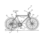
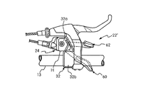
図1〜3に、本発明の第1実施形態にかかるフロント(第1)シフト操作装置20及びリア(第2)シフト操作装置22と、これらの装置を備える自転車10とを示す。自転車10は、基本的には、フレーム12と、ドライブトレインすなわち変速機14と、フロントホイール16と、リアホイール18とを備える。フレーム12には、中心軸すなわち中心線A(図5等参照)を有するハンドルバー13が回動可能に連結される。詳細には、ハンドルバー13は、フレーム12のフロントフォークに固定して連結され、これにより、フロントホイール16を介して自転車10の操縦を行う。
[First Embodiment]
1 to 3 show a front (first) shift operation device 20 and a rear (second) shift operation device 22 according to a first embodiment of the present invention, and a bicycle 10 including these devices. The bicycle 10 basically includes a frame 12, a drive train or transmission 14, a front wheel 16, and a rear wheel 18. A handle bar 13 having a center axis, that is, a center line A (see FIG. 5 and the like) is rotatably connected to the frame 12. Specifically, the handle bar 13 is fixedly connected to the front fork of the frame 12, and thereby the bicycle 10 is operated via the front wheel 16.

ドライブトレイン、すなわち変速機14は、フロントディレーラ15と、リアディレーラ17と、チェーンCと、リアホイール18に連結された複数のリアスプロケットRSと、複数のフロントスプロケットFSが連結されたフロントクランクFCとを備える。フロント及びリアディレーラ15,17はフレーム12に連結されており、これにより、従来と同様に、チェーンCを種々のスプロケットFS,RS間で横方向に移動/シフトさせる。リアスプロケットRSは、フリーホイールを介してリアホイール18に連結されており、これにより、チェーンCを介して選択的にリアホイール18を回転させて、従来と同様に自転車10を駆動する。   The drive train, that is, the transmission 14, includes a front derailleur 15, a rear derailleur 17, a chain C, a plurality of rear sprockets RS connected to the rear wheel 18, and a front crank FC connected to a plurality of front sprockets FS. Prepare. The front and rear derailleur 15 and 17 are connected to the frame 12, thereby moving / shifting the chain C laterally between the various sprockets FS and RS as in the prior art. The rear sprocket RS is coupled to the rear wheel 18 via a free wheel, and thereby selectively rotates the rear wheel 18 via the chain C to drive the bicycle 10 as in the conventional case.

フロントシフト操作装置20は、フロント(第1)ボーデン制御ケーブル21を介してフロントディレーラ15に機能的に連結されており、これにより、ほぼ従来と同様に、フロントディレーラ15をフロントスプロケットFSにわたって横方向にシフトさせる。同様に、リアシフト操作装置22は、リア(第2)ボーデン制御ケーブル23を介してリアディレーラ17に機能的に連結されており、これにより、ほぼ従来と同様に、リアディレーラ17をリアスプロケットRSにわたって横方向にシフトさせる。フロント及びリア制御ケーブル21,23は、長さを除いて同一で、基本的に従来と同様のものである。制御ケーブル21は、アウターケース21b内でスライド可能に収容されるインナーワイヤ21aを備えており、制御ケーブル23はアウターケース23b内でスライド可能に収容されるインナーワイヤ23aを備える。   The front shift operating device 20 is operatively connected to the front derailleur 15 via the front (first) Bowden control cable 21, so that the front derailleur 15 is moved laterally across the front sprocket FS almost as in the prior art. Shift to. Similarly, the rear shift operating device 22 is operatively connected to the rear derailleur 17 via the rear (second) Bowden control cable 23, so that the rear derailleur 17 is arranged in the lateral direction over the rear sprocket RS almost as in the prior art. Shift to. The front and rear control cables 21 and 23 are the same except for the length, and are basically the same as the conventional ones. The control cable 21 includes an inner wire 21a that is slidably accommodated in the outer case 21b, and the control cable 23 includes an inner wire 23a that is slidably accommodated in the outer case 23b.

フロントブレーキ19aは自転車フレーム12のフロントフォークに連結されており、リアブレーキ19bは自転車フレーム12のリア側三角部に連結される。フロント及びリアブレーキ19a,19bは、摩擦力をフロント及びリアホイール16,18のフロントリム及びリアリムに選択的に印加し、これにより、従来と同様に、フロント及びリアホイール16,18の回転をそれぞれ選択的に止める。例示した実施形態においては、それぞれのフロント及びリアシフト操作装置20,22は、それぞれのブレーキ操作装置とは独立している。しかしながら、シフト操作装置20,22は、一体型ブレーキ操作装置として設計されうる。   The front brake 19a is connected to the front fork of the bicycle frame 12, and the rear brake 19b is connected to the rear triangular portion of the bicycle frame 12. The front and rear brakes 19a and 19b selectively apply a frictional force to the front and rear rims of the front and rear wheels 16 and 18, respectively, thereby rotating the front and rear wheels 16 and 18 respectively as in the prior art. Stop selectively. In the illustrated embodiment, each front and rear shift operating device 20, 22 is independent of each brake operating device. However, the shift operation devices 20 and 22 can be designed as an integrated brake operation device.

フロント及びリアシフト操作装置20,22を除いて、自転車10の種々のパーツは、以下に述べるように、従来と同様である。したがって、フロント及びリアシフト操作装置20,22と関連するものを除いて、自転車10の他のパーツは、詳細には説明、例示しない。よって、本発明の範囲を逸脱しない限り、自転車10の各種部品あるいはパーツには種々の変形が可能である。   Except for the front and rear shift operation devices 20 and 22, the various parts of the bicycle 10 are the same as the conventional ones as described below. Accordingly, except for those associated with the front and rear shift operation devices 20, 22, other parts of the bicycle 10 will not be described or illustrated in detail. Therefore, various modifications can be made to the various parts or parts of the bicycle 10 without departing from the scope of the present invention.

また、フロントシフト操作装置20がリアシフト操作装置22の鏡像であり、フロントシフト操作装置20が3つのシフト位置のみを有し、チェーンCを3つのフロントスプロケットFSにわたって横方向に移動させることを除いて、フロント(左側)シフト操作装置20はリア(右側)シフト装置22と同一である。したがって、フロントシフト操作装置20は、ここでは詳細に説明、及び/または例示しない。すなわち、本発明にかかる構成のリアシフト操作装置22の説明、例示及び原理は、フロントシフト操作装置20に適用されること(つまり、シフト位置が少ないが、リアシフト操作装置22の鏡像であること)は、本開示から、当業者には明らかであろう。   The front shift operating device 20 is a mirror image of the rear shift operating device 22, except that the front shift operating device 20 has only three shift positions and moves the chain C laterally across the three front sprockets FS. The front (left side) shift operating device 20 is the same as the rear (right side) shift device 22. Accordingly, the front shift operating device 20 will not be described and / or illustrated in detail here. That is, the description, illustration, and principle of the rear shift operation device 22 having the configuration according to the present invention are applied to the front shift operation device 20 (that is, the shift position is small, but the mirror image of the rear shift operation device 22). From this disclosure, it will be apparent to those skilled in the art.

主に図2及び図4を参照して、リアシフト操作装置22は、基本的に、共に連結される、装着アッセンブリ24と、変速制御機構(例えば、巻き取り機構)26と、操作機構28と、保持機構30とを備え、変速機14のリアディレーラ17とチェーンCとをリアスプロケットRS間でシフトさせる。例示した実施形態においては、3枚より多いリアスプロケットRS(例えば、8あるいは9枚のスプロケットRS)があることが好ましい。したがって、リアシフト操作装置22も、好ましくは、3つ以上のシフト位置(例えば8つあるいは9つのシフト位置)を有する。いずれにせよ、リアシフト操作装置22は、リアスプロケットRSの数に対応する数のシフト位置を、好ましくは有する。もちろん、必要に応じて及び/または所望により、異なる数のシフト位置でリアディレーラ17及びリアシフト操作装置22を設計することができる。   Referring mainly to FIG. 2 and FIG. 4, the rear shift operating device 22 basically includes a mounting assembly 24, a speed change control mechanism (for example, a winding mechanism) 26, an operating mechanism 28, which are coupled together. A holding mechanism 30 is provided to shift the rear derailleur 17 and the chain C of the transmission 14 between the rear sprockets RS. In the illustrated embodiment, there are preferably more than three rear sprockets RS (eg, 8 or 9 sprockets RS). Therefore, the rear shift operating device 22 preferably also has three or more shift positions (for example, eight or nine shift positions). In any case, the rear shift operating device 22 preferably has a number of shift positions corresponding to the number of rear sprockets RS. Of course, the rear derailleur 17 and the rear shift operating device 22 can be designed with different numbers of shift positions as required and / or desired.

変速制御機構26、操作機構28及び保持機構30は装着アッセンブリ24によって支持される。変速制御機構26は、操作機構28及び保持機構30によって制御されて、リアディレーラ17を複数のシフト位置のそれぞれに制御ケーブル23を介して選択的に保持する。このように、制御ケーブル23のインナーワイヤ23a及びリアディレーラ17も、また、複数のシフト位置のそれぞれに選択的に保持される。リア制御ケーブル23のインナーワイヤ23aは変速制御機構26に連結され、これにより、変速制御機構26の移動(回転)が制御ケーブル23のインナーワイヤ23aを巻き上げ(巻き取り)あるいは解放(巻き戻し)し、リアディレーラ17をリアスプロケットRS間で作動/移動/シフトさせる。   The transmission control mechanism 26, the operation mechanism 28, and the holding mechanism 30 are supported by the mounting assembly 24. The transmission control mechanism 26 is controlled by the operation mechanism 28 and the holding mechanism 30 to selectively hold the rear derailleur 17 at each of a plurality of shift positions via the control cable 23. Thus, the inner wire 23a and the rear derailleur 17 of the control cable 23 are also selectively held at each of the plurality of shift positions. The inner wire 23a of the rear control cable 23 is connected to the speed change control mechanism 26, whereby the movement (rotation) of the speed change control mechanism 26 winds up (winds up) or releases (rewinds) the inner wire 23a of the control cable 23. The rear derailleur 17 is operated / moved / shifted between the rear sprockets RS.

もちろん、必要に応じて、及び/または所望により、変速制御機構26は、機械的及び/またはケーブル作動でなくてもよい。例えば、必要に応じて、及び/または所望により、変速制御機構26は、電気的及び/または空気式自転車用部材を作動するよう構成しうる。また、必要に応じて、及び/または所望により、たとえ、変速制御機構26が機械的であり、制御ケーブル23をとともに用いられるよう設計されている場合であっても、インナーワイヤ23aを巻き上げ及び解放する変速制御機構のための種々の構造が実現可能である。   Of course, the transmission control mechanism 26 may not be mechanical and / or cable actuated as needed and / or desired. For example, the transmission control mechanism 26 may be configured to actuate an electrical and / or pneumatic bicycle member as needed and / or desired. In addition, if necessary and / or desired, even if the speed change control mechanism 26 is mechanical and designed to be used with the control cable 23, the inner wire 23a is wound up and released. Various structures for the shifting control mechanism can be realized.

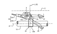
主に図2及び図4〜図6を参照して、装着アッセンブリ24は、変速制御機構26、操作機構28及び保持機構30を支持する構造を形成する、ともに連結された複数の固定部材を基本的に備える。より詳細には、装着アッセンブリ24は、基本的に、メインすなわちハンドルバー装着部32と、ベースプレート34と、中間プレート36と、レバー保持プレート38とを備える。ベースプレート34、中間プレート36及びレバー保持プレート38は、基本的に、メイン固定ボルト40(第1ピボットアクスル)及び固定ナット44によって、ともに連結される。   Referring mainly to FIGS. 2 and 4 to 6, the mounting assembly 24 forms a structure that supports the speed change control mechanism 26, the operation mechanism 28, and the holding mechanism 30, and is based on a plurality of fixing members coupled together. Be prepared. More specifically, the mounting assembly 24 basically includes a main or handlebar mounting portion 32, a base plate 34, an intermediate plate 36, and a lever holding plate 38. The base plate 34, the intermediate plate 36 and the lever holding plate 38 are basically connected together by a main fixing bolt 40 (first pivot axle) and a fixing nut 44.

ベースプレート34、中間プレート36及びレバー保持プレート38は、好ましくは、間隔が空けられ、固定ボルト40を介して連結され、変速制御機構26、操作機構28及び保持機構30のパーツをそれらの間に収容する。具体的には、リアシフト操作装置22の種々の他のパーツ(つまり、変速制御機構26、操作機構28及び保持機構30の部品)は、以下により詳細に説明する通り、移動可能に、あるいは移動不能に装着アッセンブリ24の部品に連結される。ベースプレート34、中間プレート36及び保持プレート38は、メイン固定ボルトに回転不能に装着される。   The base plate 34, the intermediate plate 36 and the lever holding plate 38 are preferably spaced apart and connected via a fixing bolt 40 to accommodate the parts of the speed change control mechanism 26, the operating mechanism 28 and the holding mechanism 30 therebetween. To do. Specifically, various other parts of the rear shift operating device 22 (that is, parts of the shift control mechanism 26, the operating mechanism 28, and the holding mechanism 30) are movable or non-movable as will be described in more detail below. To the components of the mounting assembly 24. The base plate 34, the intermediate plate 36, and the holding plate 38 are non-rotatably attached to the main fixing bolt.

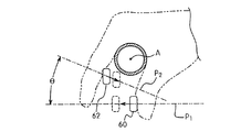
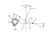
より具体的には、以下に説明する通り、保持機構30は、ベースプレート34と中間プレート36との間に連結される。操作機構28のあるパーツは、回動可能に装着されて、第1固定ピボットアクスル40の第1旋回中心線Xの回りに回転する。第2固定ピボットピン42は、ベースプレート34に移動不能に連結され、これにより、本発明にかかる、第1旋回中心線Xに対して傾斜した第2旋回中心線Yの回りで回転のため、操作機構28の他のパーツを支持する。好ましくは、第2旋回中心線Yは、第1旋回中心線Xに対して、非平行で、かつ、非垂直である。例示した実施形態においては、第2旋回中心線Yは、第1旋回中心線Xと交差しない。旋回中心線X,Yの配置は以下により詳細に説明する。   More specifically, as will be described below, the holding mechanism 30 is connected between the base plate 34 and the intermediate plate 36. A part with the operation mechanism 28 is rotatably mounted and rotates around the first turning center line X of the first fixed pivot axle 40. The second fixed pivot pin 42 is immovably connected to the base plate 34, so that the second fixed pivot pin 42 is operated for rotation about the second turning center line Y inclined with respect to the first turning center line X according to the present invention. Support other parts of mechanism 28. Preferably, the second turning center line Y is non-parallel to the first turning center line X and non-perpendicular. In the illustrated embodiment, the second turning center line Y does not intersect the first turning center line X. The arrangement of the turning center lines X and Y will be described in more detail below.

好ましくは、ハウジングHが、従来と同様に、リアシフト操作装置22のパーツを収容する。詳細には、ハウジングHは、ともにスナップ結合される、あるいは留め具によって連結される2つのピースを備えており、装着アッセンブリ24(つまり、ベースプレート34、中間プレート36及び保持プレート38)、変速制御機構26、操作機構38及び保持機構30のパーツを収容する。ハウジングHは、従来と同様に、プラスチック、軽量金属材料あるいはこの技術分野において既知の他の材料で構成される。ハンドルバー装着部32は、従来と同様に、ハウジングH及び/またはベースプレート34に移動不能に連結される。ハウジングHは、本発明において重大ではない。また、ハウジングHなどのハウジングはこの技術分野においてよく知られている。したがって、ハウジングHは、ここでは詳に説明、及び/または例示しない。   Preferably, the housing H accommodates the parts of the rear shift operating device 22 as in the prior art. Specifically, the housing H includes two pieces that are snapped together or connected by fasteners, the mounting assembly 24 (ie, the base plate 34, the intermediate plate 36, and the holding plate 38), the speed change control mechanism. 26, the parts of the operation mechanism 38 and the holding mechanism 30 are accommodated. The housing H is constructed of plastic, lightweight metal material, or other materials known in the art, as is conventional. The handlebar mounting portion 32 is movably connected to the housing H and / or the base plate 34 as in the conventional case. The housing H is not critical in the present invention. Also, housings such as housing H are well known in the art. Accordingly, the housing H will not be described and / or illustrated in detail here.

ハンドルバー装着部32は、基本的に、メイン/シフト装着プレート32aと、ハンドルバー装着ブラケット(つまり、管状クランプ部分)32bとを備える。オプションとして、右手側(リア)ブレーキ制御装置を従来と同様に、メイン装着部32と一体化することもできる。好ましくは、メイン/シフト装着部32a及びハンドルバー装着ブラケット32bは、従来と同様に、装着ブラケット32b及びネジが形成された留め具32cを介してハンドルバー13に移動不能に連結される一体の、単一部材として、ともに形成される。ハンドルバー装着部32は、好ましくは、鋳造アルミニウムなどの、軽量な、剛性材料で構成される。もちろん、必要に応じて及び/または所望により、いずれの適切な材料を利用しうる。いずれの場合も、装着アッセンブリ24及びハウジングHは、移動不能にともに連結される。   The handlebar mounting portion 32 basically includes a main / shift mounting plate 32a and a handlebar mounting bracket (that is, a tubular clamp portion) 32b. As an option, the right-hand side (rear) brake control device can be integrated with the main mounting portion 32 as in the prior art. Preferably, the main / shift mounting portion 32a and the handlebar mounting bracket 32b are integrally connected to the handlebar 13 through a mounting bracket 32b and a fastener 32c formed with a screw so as to be immovable. They are formed together as a single member. The handlebar mounting portion 32 is preferably made of a lightweight, rigid material such as cast aluminum. Of course, any suitable material may be utilized as needed and / or desired. In either case, the mounting assembly 24 and the housing H are connected together so as not to move.

主に図4、図8及び図9を参照して、ベースプレート34は、比較的薄い、平坦な部材である。ベースプレート34は、基本的に、メインプレート部分34aと、そのメインプレート部分34aに対して傾斜した第2プレート部分34bとを備える。第2固定ピボットピンは、第2プレート部分34bに連結され、これにより、第2旋回中心線Yは第1旋回中心線Xに対して傾斜する。第1ピボットアクスル(ボルト)40はメインプレート部分34aに連結され、これにより、第1旋回中心線Xはメインプレート部分34aに対して垂直に延びる。第2固定ピボットピン42は第2プレート部分34bから垂直に延び、これにより、第1及び第2旋回中心線X,Yの傾斜がメインプレート部分34aと第2プレート部分34bとの間の傾斜に対応する。図6からわかる通り、本実施形態において、第2旋回中心線Yの上端は、第2旋回中心線Yの下端よりもハンドルバー13の近くに位置する。   Referring mainly to FIGS. 4, 8, and 9, the base plate 34 is a relatively thin, flat member. The base plate 34 basically includes a main plate portion 34a and a second plate portion 34b inclined with respect to the main plate portion 34a. The second fixed pivot pin is connected to the second plate portion 34b, whereby the second turning center line Y is inclined with respect to the first turning center line X. The first pivot axle (bolt) 40 is connected to the main plate portion 34a, whereby the first turning center line X extends perpendicularly to the main plate portion 34a. The second fixed pivot pin 42 extends vertically from the second plate portion 34b, so that the inclination of the first and second pivot centerlines X and Y is inclined between the main plate portion 34a and the second plate portion 34b. Correspond. As can be seen from FIG. 6, in the present embodiment, the upper end of the second turning center line Y is located closer to the handle bar 13 than the lower end of the second turning center line Y.

メインプレート部分34aは、メイン固定ボルト40を回転不能に支持する。第2プレート部分34bは、第2固定ピボットアクスル42を移動不能に支持する。詳細には、第2プレート部分34bは、第2固定ピボットピン42の嵌合突起を回転不能に収容するよう構成された非円形開口部を備える。メインプレート部分34aは、そこから下方に延びて、従来と同様に、制御ケーブル23の一部を収容するケーブル支持突起34cを備える。また、メインプレート部分34aは、そこから下方に延びて、中間プレート36と接する1組の突起34dを備える。ベースプレート34は、好ましくは、シート状金属などの、軽量剛性材料で構成される。ベースプレート34は、メインプレート部分34aと中間プレート36との間に配置される。ベースプレート34は、回転不能に係合するメイン固定ボルト40を備え、これにより、中間プレート36及びレバー保持プレート38を回転不能に支持する。   The main plate portion 34a supports the main fixing bolt 40 so as not to rotate. The second plate portion 34b supports the second fixed pivot axle 42 so as not to move. Specifically, the second plate portion 34b includes a non-circular opening configured to non-rotatably receive the fitting protrusion of the second fixed pivot pin 42. The main plate portion 34a includes a cable support protrusion 34c that extends downward therefrom and accommodates a part of the control cable 23 as in the conventional case. The main plate portion 34 a includes a pair of protrusions 34 d that extend downward from the main plate portion 34 a and contact the intermediate plate 36. The base plate 34 is preferably made of a lightweight rigid material such as sheet metal. The base plate 34 is disposed between the main plate portion 34 a and the intermediate plate 36. The base plate 34 includes a main fixing bolt 40 that is non-rotatably engaged, thereby supporting the intermediate plate 36 and the lever holding plate 38 so as not to rotate.

中間プレート36は、好ましくは、いくつかの薄い平坦な部分で形成された単一の部材である。中間プレート36は、第1固定ピボットアクスル40に回転不能に支持され、好ましくは、変形されたシート状金属などの軽量剛性材料で構成される。また、中間プレート36はベースプレート34とレバー保持プレート38との間に配置される。変速制御機構26は、ベースプレート34の下面と中間プレート36の上面との間にメイン固定ボルト40で支持される。中間プレート36は、メインプレート部分36aと、上方に延びる突起36bと、下方に延びる突起36cとを備える。中間プレート36の例えば突起36b,36cは、操作機構28のパーツと選択的に接するよう配置される。保持機構30は、中間プレート36のメインプレート部分36aとベースプレート34のメインプレート部分34aとの間で支持される。保持機構30は、さらに、ベースプレート34と中間プレート36との間の相対回転を防止する。   The intermediate plate 36 is preferably a single member formed of several thin flat portions. The intermediate plate 36 is non-rotatably supported by the first fixed pivot axle 40 and is preferably made of a lightweight rigid material such as a deformed sheet metal. The intermediate plate 36 is disposed between the base plate 34 and the lever holding plate 38. The transmission control mechanism 26 is supported by a main fixing bolt 40 between the lower surface of the base plate 34 and the upper surface of the intermediate plate 36. The intermediate plate 36 includes a main plate portion 36a, a protrusion 36b extending upward, and a protrusion 36c extending downward. For example, the protrusions 36 b and 36 c of the intermediate plate 36 are disposed so as to selectively contact the parts of the operation mechanism 28. The holding mechanism 30 is supported between the main plate portion 36 a of the intermediate plate 36 and the main plate portion 34 a of the base plate 34. The holding mechanism 30 further prevents relative rotation between the base plate 34 and the intermediate plate 36.

レバー保持プレート38は、好ましくは、薄い平坦な部材であり、シート状金属などの軽量剛性材料で構成される。また、レバー保持プレート38はベースプレート34から反対側の中間プレート36上に配置される。したがって、レバー保持プレート38は、メイン装着部32から最も離れて配置される。レバー保持プレート38は、固定ボルト40を介してベースプレート34に固定して回転不能に連結される。具体的には、レバー保持プレート38は、メイン固定ボルト40の下端と回転不能に係合し、ナット44を介してメイン固定ボルト40に保持される。このように、レバー保持プレート38、中間プレート36及びベースプレート34は、ともに固定して回転不能に連結され、これにより、装着アッセンブリ24のパーツを形成する。以下に説明する通り、レバー保持プレート38は、操作機構28の一部と係合する少なくとも1つの付勢スロット38aを備える。例示した実施形態においては、レバー保持プレート38は、複数の付勢スロット38aを備える。本実施形態においては、装着アッセンブリ24は、米国特許6,694,840号に開示された従来の装着アッセンブリと同様である。したがって、本発明の説明において必要がある場合を除いて、ここでは、装着アッセンブリ24を、さらに詳細には、説明及び/または例示しない。   The lever holding plate 38 is preferably a thin flat member and is made of a lightweight rigid material such as sheet metal. The lever holding plate 38 is disposed on the intermediate plate 36 opposite to the base plate 34. Therefore, the lever holding plate 38 is arranged farthest from the main mounting portion 32. The lever holding plate 38 is fixed to the base plate 34 via a fixing bolt 40 and is non-rotatably connected. Specifically, the lever holding plate 38 is engaged with the lower end of the main fixing bolt 40 so as not to rotate, and is held by the main fixing bolt 40 via the nut 44. In this manner, the lever holding plate 38, the intermediate plate 36, and the base plate 34 are fixedly coupled together so as not to rotate, thereby forming parts of the mounting assembly 24. As will be described below, the lever holding plate 38 includes at least one biasing slot 38 a that engages a part of the operation mechanism 28. In the illustrated embodiment, the lever retaining plate 38 includes a plurality of biasing slots 38a. In this embodiment, the mounting assembly 24 is similar to the conventional mounting assembly disclosed in US Pat. No. 6,694,840. Accordingly, the mounting assembly 24 is not described and / or illustrated in further detail herein except where necessary in the description of the present invention.

図4〜図10を参照して、変速制御機構26をより詳細に説明する。上述の通り、変速制御機構26は、装着アッセンブリ24のベースプレート34と中間プレート36との間でメイン固定ボルト40に装着される。例示した実施形態においては、変速制御機構26は、制御ケーブル23のインナーワイヤ23aを選択的に引っ張り/解放する機械的ケーブル巻き上げ機構である。変速制御機構26は、基本的には、巻き上げ部材(ケーブル巻き取り部材)52と、ラチェット部材54と、メイン付勢部材56と、ユニットスペーサ58とを備える。例示した実施形態においては、巻き上げ部材52及びラチェット部材54は、ともに回転不能に連結される別部材である。メイン付勢部材56は、巻き上げ部材52及びラチェット部材54を所定の方向、例えば、図4において、通常、反時計回り方向CCWに付勢するトーションバネである。変速制御機構26は、操作機構28及び保持機構30に機能的に連結され、これにより、巻き上げ部材52を複数のシフト位置に選択的に保持する。   The shift control mechanism 26 will be described in more detail with reference to FIGS. As described above, the shift control mechanism 26 is mounted on the main fixing bolt 40 between the base plate 34 and the intermediate plate 36 of the mounting assembly 24. In the illustrated embodiment, the shift control mechanism 26 is a mechanical cable winding mechanism that selectively pulls / releases the inner wire 23 a of the control cable 23. The transmission control mechanism 26 basically includes a winding member (cable winding member) 52, a ratchet member 54, a main urging member 56, and a unit spacer 58. In the illustrated embodiment, the winding member 52 and the ratchet member 54 are separate members that are non-rotatably connected. The main urging member 56 is a torsion spring that urges the winding member 52 and the ratchet member 54 in a predetermined direction, for example, generally in the counterclockwise direction CCW in FIG. The speed change control mechanism 26 is operatively connected to the operation mechanism 28 and the holding mechanism 30, thereby selectively holding the winding member 52 at a plurality of shift positions.

巻き上げ部材52は、好ましくは、モールディング等によって、一体の単一部材として形成されたステップ状部材である。巻き上げ部材52は、好ましくは、硬質プラスチックなどの軽量剛性材料で構成される。巻き上げ部材52は、従来と同様に、制御ケーブル23のインナーワイヤ23aが連結されるよう構成される。巻き上げ部材52は、メイン固定ボルト49の回りの回転のために、装着アッセンブリ24に回転自在に連結される。しかしながら、以下に説明する通り、操作機構28及び保持機構30は、ラチェット部材54との係合を介して巻き上げ部材52の回転を制御する。ラチェット部材54は、巻き上げ部材52とともに回転するように巻上げ部材52に対して回転不能に連結される。   The winding member 52 is preferably a step-like member formed as an integral single member by molding or the like. The winding member 52 is preferably made of a lightweight rigid material such as hard plastic. The winding member 52 is configured such that the inner wire 23a of the control cable 23 is connected to the winding member 52, as in the prior art. The winding member 52 is rotatably connected to the mounting assembly 24 for rotation about the main fixing bolt 49. However, as will be described below, the operation mechanism 28 and the holding mechanism 30 control the rotation of the winding member 52 through the engagement with the ratchet member 54. The ratchet member 54 is non-rotatably connected to the winding member 52 so as to rotate together with the winding member 52.

ラチェット部材54は、巻き上げ部材52と中間プレート36との間に配置される。ラチェット部材54は、好ましくは、外周に形成された複数の形状の異なる歯を有する薄い平坦な部材であり、操作機構28及び保持機構30と係合する。好ましくは、ラチェット部材54は、シート状金属などの軽量剛性材料で構成される。付勢部材56は、好ましくは、巻き上げ部材52及びラチェット部材54にメイン固定ボルト40の回りで付勢力を印加するトーションバネである。付勢部材(バネ)56の両端は、ベースプレート34及び巻き上げ部材52と係合し、付勢力を印加する。ユニットスペーサ58は、好ましくは、軽量剛性部材で構成された管状部材であり、一端がベースプレート34の下面と接し、他端が中間プレート36の上面と接して、中間プレート36をベースプレートから間隔を空けて配置する。   The ratchet member 54 is disposed between the winding member 52 and the intermediate plate 36. The ratchet member 54 is preferably a thin flat member having a plurality of teeth of different shapes formed on the outer periphery, and engages with the operation mechanism 28 and the holding mechanism 30. The ratchet member 54 is preferably made of a lightweight rigid material such as sheet metal. The biasing member 56 is preferably a torsion spring that applies a biasing force around the main fixing bolt 40 to the winding member 52 and the ratchet member 54. Both ends of the urging member (spring) 56 engage with the base plate 34 and the winding member 52 to apply an urging force. The unit spacer 58 is preferably a tubular member made of a lightweight and rigid member, and has one end in contact with the lower surface of the base plate 34 and the other end in contact with the upper surface of the intermediate plate 36 so that the intermediate plate 36 is spaced from the base plate. Arrange.

操作機構28は、ラチェット部材54を介して、メイン付勢部材56の付勢力に抗して巻き上げ部材52を移動させ、これにより、制御ケーブル23を巻き上げる(巻き取る)。保持機構30は、巻き上げ部材52及びラチェット部材54をシフト位置のそれぞれに選択的に保持する。保持機構30は、操作機構28によって解放され、これにより、巻き上げ部材52を解放する(巻き戻す)。本実施形態においては、変速制御機構26は、米国特許6,694,840号に開示された従来の巻き取り機構と同様である。したがって、本発明の説明に必要な場合を除いて、ここでは、変速制御機構26を、さらに詳細には、説明及び/または例示しない。   The operating mechanism 28 moves the winding member 52 against the urging force of the main urging member 56 via the ratchet member 54, thereby winding up (winding up) the control cable 23. The holding mechanism 30 selectively holds the winding member 52 and the ratchet member 54 at each of the shift positions. The holding mechanism 30 is released by the operation mechanism 28, thereby releasing (rewinding) the winding member 52. In the present embodiment, the shift control mechanism 26 is the same as the conventional winding mechanism disclosed in US Pat. No. 6,694,840. Accordingly, the shift control mechanism 26 is not described and / or illustrated in further detail herein except where necessary to describe the present invention.

さらに図4〜10を参照して、操作機構28をより詳細に説明する。操作機構28は、基本的に、第1シフト操作部材(第1シフトレバー)60と、第2シフト操作部材(第2シフトレバー)62と、操作すなわち解放プレート(部材)64と、爪機構66とを備える。第1シフト操作部材60は、メイン固定ボルト40に回動可能に(つまり、第1旋回中心線X回りに回転するよう)装着される。一方、第2シフト操作部材62は、第2固定ボルト42に回動可能に(つまり、第2旋回中心線Y回りに回転するよう)装着される。解放部材(プレート)64は、メイン固定ボルト40に、中間プレート36の下面に隣接して、回動可能に(つまり、第1旋回中心線X回りに回転するよう)装着される。   Further, the operation mechanism 28 will be described in more detail with reference to FIGS. The operation mechanism 28 basically includes a first shift operation member (first shift lever) 60, a second shift operation member (second shift lever) 62, an operation, that is, a release plate (member) 64, and a pawl mechanism 66. With. The first shift operation member 60 is attached to the main fixing bolt 40 so as to be rotatable (that is, to rotate around the first turning center line X). On the other hand, the second shift operation member 62 is attached to the second fixing bolt 42 so as to be rotatable (that is, to rotate around the second turning center line Y). The release member (plate) 64 is attached to the main fixing bolt 40 adjacent to the lower surface of the intermediate plate 36 so as to be rotatable (that is, to rotate around the first turning center line X).

第1シフト操作部材60は、ステップ状管状第1スペーサ68によって、第1固定ピボットアクスル40に回転可能に支持される。一方、解放プレート64は、ステップ状管状第2スペーサ70によって、第1固定ピボットアクスル40に支持される。第1スペーサ68は、第2スペーサ70内に部分的に収容されるよう構成される。従来と同様に、第1操作部材60は、第1付勢部材(トーションバネ)61によって、通常、第1レスト位置に向かって付勢され、一方、解放プレート64は、付勢部材(トーションバネ)によって、通常、レスト位置に付勢される。詳細には、付勢部材61は、レバー保持プレート38の付勢スロット38aの1つと係合する一端と、第1操作部材60と係合し第1操作部材を図4で見て反時計回りの方向CCWに付勢する他端とを有する。付勢部材65は、解放プレート64と係合する一端と、第1操作部材60と係合し解放プレート64を図4で見て時計回りの方向に付勢する他端とを有する。   The first shift operation member 60 is rotatably supported by the first fixed pivot axle 40 by a step-shaped tubular first spacer 68. On the other hand, the release plate 64 is supported on the first fixed pivot axle 40 by the step-like tubular second spacer 70. The first spacer 68 is configured to be partially accommodated in the second spacer 70. As in the prior art, the first operating member 60 is normally biased toward the first rest position by a first biasing member (torsion spring) 61, while the release plate 64 is biased by a biasing member (torsion spring). ) Is normally biased to the rest position. Specifically, the urging member 61 is engaged with one of the urging slots 38a of the lever holding plate 38, and is engaged with the first operating member 60 and counterclockwise when the first operating member is viewed in FIG. And the other end biased in the direction CCW. The biasing member 65 has one end that engages with the release plate 64 and the other end that engages with the first operating member 60 and biases the release plate 64 in a clockwise direction as viewed in FIG.

解放プレート64は、第2シフト操作部材62と保持機構30との間に機能的に連結され、これにより、第2シフト操作部材62の第2レスト位置から第2シフト位置への移動が、保持機構を作動する。そして次に、保持機構30は、変速機構30と機能的に係合し、これにより、以下に説明する通り、第2操作部材62が移動されて制御ケーブル23を解放すなわち巻き戻す。爪機構66は、第1シフト操作部材60に装着され、これにより、第1シフト操作部材60の第1レスト位置から第1シフト位置への移動によって爪機構66が変速制御機構26と機能的に係合して、制御ケーブル23のインナーワイヤ23aを巻き取る。   The release plate 64 is operatively connected between the second shift operation member 62 and the holding mechanism 30, whereby the movement of the second shift operation member 62 from the second rest position to the second shift position is held. Activate the mechanism. Then, the holding mechanism 30 is functionally engaged with the speed change mechanism 30, whereby the second operating member 62 is moved to release or rewind the control cable 23 as will be described below. The claw mechanism 66 is attached to the first shift operation member 60, whereby the claw mechanism 66 is functionally connected to the speed change control mechanism 26 by the movement of the first shift operation member 60 from the first rest position to the first shift position. Engage and wind up the inner wire 23a of the control cable 23.

より具体的には、爪機構66は、第1操作部材60がライダーによって通常のレスト位置からシフト位置に移動されたとき、ラチェット部材54と係合するよう構成される。第1操作部材60は、第1シフト面Pに沿ってメイン固定ボルト40の第1旋回中心線Xの回りに回動する。第1シフト面Pは第1旋回中心線Xに対して垂直である。したがって、第1操作部材60が移動されると、爪機構66はラチェット部材54を、1つのシフト位置だけ付勢部材56の付勢力に抗して回転させる。こうして、巻き上げ部材52も回転され、これにより、シフトケーブル23のインナーワイヤ23aを引っ張り、リアディレーラ17を次のシフト位置にシフトさせる。 More specifically, the pawl mechanism 66 is configured to engage with the ratchet member 54 when the first operating member 60 is moved from the normal rest position to the shift position by the rider. The first operating member 60 pivots about the first pivot axis X of the main fixing bolt 40 along the first shifting plane P 1. The first shift plane P 1 is perpendicular to the first turning center line X. Therefore, when the first operating member 60 is moved, the pawl mechanism 66 rotates the ratchet member 54 against the biasing force of the biasing member 56 by one shift position. Thus, the winding member 52 is also rotated, thereby pulling the inner wire 23a of the shift cable 23 and shifting the rear derailleur 17 to the next shift position.

爪機構66は、基本的に、爪ピボットピン72と、爪バネ74と、爪部材76と、保持クリップ78とを備える。爪ピボットピン72は、第2操作部材60に装着される下端部を有する。爪部材76は、爪ピボットピン72に上端部に装着され、爪バネ74が、通常、爪部材76を第1操作部材60に対して相対的に付勢している。具体的には、爪バネ74は、爪部材76と係合する上端部と、第1操作部材60と係合し、通常、爪部材76をラチェット部材54と係合するよう付勢する下端部とを有する。このように、爪部材76はラチェット部材54と選択的に接するよう構成される。   The claw mechanism 66 basically includes a claw pivot pin 72, a claw spring 74, a claw member 76, and a holding clip 78. The claw pivot pin 72 has a lower end portion attached to the second operation member 60. The claw member 76 is attached to the claw pivot pin 72 at its upper end, and the claw spring 74 normally biases the claw member 76 relative to the first operation member 60. Specifically, the claw spring 74 is engaged with the claw member 76 and the lower end portion that is engaged with the first operation member 60 and normally urges the claw member 76 into engagement with the ratchet member 54. And have. Thus, the claw member 76 is configured to selectively contact the ratchet member 54.

具体的には、第1操作部材60がレスト位置からシフト位置に移動されたとき、爪部材76は、ラチェット部材54と係合し、これにより、ラチェット部材54及び巻き上げ部材52をメイン固定ボルト40の回りに回転させる。しかしながら、第1操作部材60が通常のレスト位置にあるとき、爪部材76は中間プレート36と接し、これにより、爪部材76をラチェット部材54と非係合に保持する。したがって、第2操作部材62が作動された場合、例えば、以下に説明する通り、保持機構30が解放された場合、ラチェット部材54及び巻き上げ部材52は、メイン付勢部材56の付勢力により、回転することができる。   Specifically, when the first operation member 60 is moved from the rest position to the shift position, the claw member 76 engages with the ratchet member 54, thereby causing the ratchet member 54 and the winding member 52 to move to the main fixing bolt 40. Rotate around. However, when the first operating member 60 is in the normal rest position, the claw member 76 contacts the intermediate plate 36, thereby holding the claw member 76 out of engagement with the ratchet member 54. Therefore, when the second operation member 62 is operated, for example, as described below, when the holding mechanism 30 is released, the ratchet member 54 and the winding member 52 are rotated by the urging force of the main urging member 56. can do.

第1操作部材60が通常のレスト位置に移動して戻るとき、爪機構66は中間プレート36と係合し、これにより、爪機構66をラチェット部材54から非係合にする。しかしながら、保持機構30はラチェット部材54と係合し、これにより、巻き上げ部材52及びラチェット部材54を、バネ56の付勢力に抗して新しいシフト位置に保持する。例示した実施形態においては、第1操作部材60の移動によって、あるシフト位置から次の隣接するシフト位置への一の回転方向における巻き上げ部材52の1つのシフトのみが行われる。   When the first operating member 60 moves back to the normal rest position, the claw mechanism 66 engages with the intermediate plate 36, thereby disengaging the claw mechanism 66 from the ratchet member 54. However, the holding mechanism 30 engages with the ratchet member 54, thereby holding the winding member 52 and the ratchet member 54 in the new shift position against the biasing force of the spring 56. In the illustrated embodiment, the movement of the first operating member 60 causes only one shift of the winding member 52 in one rotational direction from one shift position to the next adjacent shift position.

本実施形態においては、爪機構66は、米国特許6,694,840号に開示された従来の爪機構と同様である。したがって、本発明の説明に必要な場合を除いて、ここでは、爪機構66を、さらに詳細には、説明及び/または例示しない。また、第1操作部材60は、ほぼ従来のものであり、変速制御機構26を、爪機構66を介して巻き取るよう、ほぼ従来と同様に機能する。したがって、本発明に関連するものを除いて、ここでは、第1操作部材60を、詳細には、記載及び/または例示をしない。詳細には、第2操作部材62の移動と関連する移動を除いて、ここでは、第1操作部材60を、詳細には、記載及び/または例示をしない。   In this embodiment, the claw mechanism 66 is the same as the conventional claw mechanism disclosed in US Pat. No. 6,694,840. Accordingly, the pawl mechanism 66 will not be described and / or illustrated in further detail herein except where necessary to describe the present invention. Further, the first operation member 60 is substantially conventional, and functions in the same manner as in the conventional case so as to wind up the speed change control mechanism 26 via the claw mechanism 66. Accordingly, except for those relating to the present invention, the first operating member 60 is not described and / or illustrated in detail here. Specifically, except for the movement associated with the movement of the second operating member 62, the first operating member 60 is not described and / or illustrated in detail here.

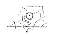
第2シフト操作部材62は、保持機構30に解放プレート64を介して機能的に連結され、これにより、ラチェット部材54及び巻き上げ部材52を選択的に解放する。言い換えれば、ライダーは第2操作部材62を第2シフト面Pに沿って第2旋回中心線Yの回りに回転させて、保持機構30をラチェット部材54から非係合にし、これにより、巻き上げ部材52及びラチェット部材54がバネ56の付勢力のもとで回転して、制御ケーブル23を巻き戻す。第2シフト面Pは第2旋回中心線Yに対して垂直である。 The second shift operation member 62 is functionally connected to the holding mechanism 30 via the release plate 64, thereby selectively releasing the ratchet member 54 and the winding member 52. In other words, the rider rotates about the second pivot axis Y along the second operating member 62 in the second shifting plane P 2, and the holding mechanism 30 from the ratchet member 54 disengaged, thereby, hoisting The member 52 and the ratchet member 54 rotate under the urging force of the spring 56 to rewind the control cable 23. The second shifting plane P 2 is perpendicular to the second pivot axis Y.

第1及び第2旋回中心線X,Y(つまり、第1及び第2固定ピボットアクスル40,42)の配置により、第1及び第2シフト面P,Pは、交差線Iに沿ってその間の角度θがおよそ30°以下となるよう交差し、人間工学的に最適な配置を提供する。 Due to the arrangement of the first and second turning center lines X and Y (that is, the first and second fixed pivot axles 40 and 42), the first and second shift surfaces P 1 and P 2 are along the intersection line I. The angle θ between them intersects so as to be about 30 ° or less, thereby providing an optimal ergonomic arrangement.

例示した実施形態において、第1及び第2シフト面P,Pは、好ましくは、交差線Iがハンドルバー13の中心線Aとほぼ平行に交差する。したがって、図5及び図6からよくわかる通り、第2旋回中心線Yは、好ましくは、中心線Aに垂直な縦方向面L内に位置し、第1旋回中心線Xは、好ましくは、縦方向面Lに対して平行である。また、第2シフト操作部材62のピボット点(第2旋回中心線Yが第2操作部材62を通る位置)は、好ましくは、中心線Aから第1旋回中心線Xよりも離れている。 In the illustrated embodiment, the first and second shift planes P 1 and P 2 preferably intersect the intersecting line I with the center line A of the handle bar 13 substantially in parallel. 5 and 6, the second turning center line Y is preferably located in the longitudinal plane L perpendicular to the center line A, and the first turning center line X is preferably longitudinal. Parallel to the direction plane L. Further, the pivot point of the second shift operation member 62 (the position where the second turning center line Y passes through the second operation member 62) is preferably separated from the first turning center line X from the center line A.

リアシフト操作装置22が自転車10に通常のライディングポジションで連結されたとき、第1シフト面Pは、第1(上部)サイド及び第2サイド(下部)サイドを有する。本実施形態において、図6からよくわかる通り、第2シフト面Pは、第1シフト面から逸れて、第2シフト面Pが第1シフト面Pの第2サイドでハンドルバー装着部32に向かって後方に(そしてハンドルバー装着部32を越えて)延びている。言い換えれば、第2シフト面Pは第1シフト面Pから逸れて、第2シフト面Pが第1シフト面Pの第2サイドで第2シフト操作部材62の移動方向に延びている。しかしながら、本発明から逸脱することなく他の配置をとることが可能である。本発明の他の好ましい実施形態を参照して後述する通り、例えば、第2シフト面Pに第1シフト面Pから逆方向に角度を持たせうる。 When the rear shift operating device 22 is connected in the normal riding position on the bicycle 10, the first shifting plane P 1 has a first (upper) side and the second side (bottom) side. In this embodiment, as can be seen from FIG. 6, the second shift surface P 2 deviates from the first shift surface, and the second shift surface P 2 is the second side of the first shift surface P 1 and the handlebar mounting portion. Extends rearwardly toward 32 (and beyond the handlebar mounting 32). In other words, the second shift surface P 2 deviates from the first shift surface P 1 , and the second shift surface P 2 extends in the moving direction of the second shift operation member 62 on the second side of the first shift surface P 1 . Yes. However, other arrangements are possible without departing from the invention. As will be described later with reference to another preferred embodiment of the present invention, for example, the second shift surface P 2 may be angled in the opposite direction from the first shift surface P 1 .

しかしながら、本発明の範囲を逸脱しない限り、本発明に種々の変形が行える。例えば、交差線Iは、ハンドルバー13の中心線Aに対して角度を持たせることもできる。いずれの場合も、シフト面P,Pは、好ましくは、旋回中心線X,Yに対してそれぞれ垂直であり、線Iに沿って交差する。交差線が中心線Aと平行でないような配置において、第1及び第2旋回中心線X,Yの配置を変形することもできる。例示した実施形態においては、第1及び第2旋回中心線X,Yは、好ましくは、互いに交差しない。しかしながら、必要に応じて、及び/または所望により、旋回中心線が交差してもよいことは、本開示から、また、当業者には明らかであろう。 However, various modifications can be made to the present invention without departing from the scope of the present invention. For example, the intersection line I can also be angled with respect to the center line A of the handlebar 13. In any case, the shift planes P 1 and P 2 are preferably perpendicular to the turning center lines X and Y, respectively, and intersect along the line I. In an arrangement in which the intersection line is not parallel to the center line A, the arrangement of the first and second turning center lines X and Y can be modified. In the illustrated embodiment, the first and second pivot centerlines X, Y preferably do not intersect each other. However, it will be apparent from this disclosure and to those skilled in the art that the pivot centerlines may intersect as needed and / or desired.

保持機構30は、第2操作部材62の押し操作毎に1つのシフト位置だけ巻き上げ部材52及びラチェット部材54を回転させるよう構成され配置される。言い換えると、ラチェット部材54は、シフト位置1つ分回転させた後、保持機構30と係合する。したがって、例示した実施形態においては、第2操作部材62の移動によって、あるシフト位置から次の隣接するシフト位置への、第1操作部材60の移動による回転方向とは反対の他方の回転方向における巻き上げ部材52の1つのシフトのみが行われる。   The holding mechanism 30 is configured and arranged to rotate the winding member 52 and the ratchet member 54 by one shift position every time the second operating member 62 is pushed. In other words, the ratchet member 54 is engaged with the holding mechanism 30 after being rotated by one shift position. Therefore, in the illustrated embodiment, the movement of the second operation member 62 causes the shift in the other rotation direction opposite to the rotation direction due to the movement of the first operation member 60 from one shift position to the next adjacent shift position. Only one shift of the winding member 52 is performed.

さらに、図4〜図10を参照して、第2シフト操作部材62は、好ましくは、変形されたシート状金属などの軽量剛性材料薄い平坦な部材で構成される。第2シフト操作部材62は、基本的に、ピボットすなわち装着部分62aと、作動突起62bと、ライダー操作部分62cとを備える。作動突起62bは、好ましくは、装着部分62aに対して角度が付けられており、作動突起62bは第1旋回中心線Xに対して平行(解放プレート64に対して垂直)である。一方、ピボット部分62aは、好ましくは、第2旋回中心線Yと垂直である(つまり、第2シフト面P内にある)。本実施形態においては、作動突起62bは装着部分62aから上方に延びている。ライダー操作部分62cは、装着部分62aから延びている。 Further, referring to FIGS. 4 to 10, the second shift operation member 62 is preferably formed of a thin flat member of a lightweight rigid material such as a deformed sheet metal. The second shift operation member 62 basically includes a pivot, that is, a mounting portion 62a, an operating projection 62b, and a rider operation portion 62c. The operating protrusion 62b is preferably angled with respect to the mounting portion 62a, and the operating protrusion 62b is parallel to the first pivot centerline X (perpendicular to the release plate 64). On the other hand, the pivot section 62a is preferably perpendicular to the second pivot axis Y (i.e., in the second shifting plane P in 2). In the present embodiment, the operating protrusion 62b extends upward from the mounting portion 62a. The rider operation part 62c extends from the mounting part 62a.

第2シフト操作部材62は、第2固定ピボットピン42に回動可能に装着される。より詳細には、第2ピボットピン42は、ピボット部分62aを通って少なくとも部分的に収容されて、第2シフト操作部材62を第2旋回中心線Yの回りに回動可能に支持する。一方、付勢部材(バネ)46は、ピボットピン42に装着され、第2シフト操作部材62に付勢力を印加し、これにより、第2シフト操作部材62を時計回り方向に第2レスト位置に向かって付勢する。具体的には、付勢部材46の一端は、従来と同様に、ベースプレート34に対して相対的に移動不能である第2固定ピボットピン42と係合する。付勢部材46の他端は、従来と同様に、第2シフト操作部材62のピボット部分62aと係合する。保持クリップ48は、従来と同様に、第2操作部材62を第2ピボットピン42に保持する。作動突起62bは解放プレート64と接するよう配置され構成される。   The second shift operation member 62 is rotatably attached to the second fixed pivot pin 42. More specifically, the second pivot pin 42 is at least partially accommodated through the pivot portion 62a and supports the second shift operation member 62 so as to be rotatable around the second turning center line Y. On the other hand, the urging member (spring) 46 is attached to the pivot pin 42 and applies an urging force to the second shift operation member 62, thereby moving the second shift operation member 62 clockwise to the second rest position. Energize towards. Specifically, one end of the urging member 46 engages with the second fixed pivot pin 42 that is not movable relative to the base plate 34 as in the prior art. The other end of the urging member 46 engages with the pivot portion 62a of the second shift operation member 62 as in the conventional case. The holding clip 48 holds the second operating member 62 on the second pivot pin 42 as in the conventional case. The operating protrusion 62b is arranged and configured to contact the release plate 64.

解放部材/プレート64は、好ましくは、変形されたシート状金属などの軽量剛性材料で構成された薄い平坦な部材である。より具体的には、解放プレート64は、基本的に、カップリング部64aと、操作部64bと、第1ピボットアクスル40から横方向に間隔を空けた配置でカップリング部64aから上方に延びる解放フランジ64cとを備える。解放プレート64は、第1ピボットピン40に回動可能に装着される。以下により詳細に説明する通り、操作部64bは作動突起62bと接し、一方、解放フランジ64cは保持機構30と選択的に係合する。したがって、解放プレート64は、保持機構30及び第2シフト操作部材62の両方と機能的に連結される。   Release member / plate 64 is preferably a thin flat member constructed of a lightweight rigid material, such as a deformed sheet metal. More specifically, the release plate 64 basically extends upward from the coupling part 64a in a laterally spaced arrangement from the coupling part 64a, the operating part 64b, and the first pivot axle 40. And a flange 64c. The release plate 64 is rotatably attached to the first pivot pin 40. As will be described in more detail below, the operating portion 64b contacts the actuation projection 62b, while the release flange 64c selectively engages the holding mechanism 30. Therefore, the release plate 64 is functionally connected to both the holding mechanism 30 and the second shift operation member 62.

さらに図4〜10を参照して、保持機構30をより詳細に説明する。保持機構30は、基本的に、保持ピボットピン80と、保持付勢部材82と、ロック部材84と、管状スペーサ86と、保持クリップ88とを備える。保持ピボットピン80は、ベースプレート34と中間プレート36とに連結され、その移動を防止する。ロック部材84は、保持ピボットピン80に回転可能に装着される。保持付勢部材82は、通常、ロック部材84を所定の位置に向かって付勢する。ロック部材84は、ラチェット部材54と係合するよう配置され構成される。また、ロック部材84は、解放プレート64の解放フランジ64cと選択的に係合するよう配置され構成される。本実施形態においては、保持機構30は、米国特許6,694,840号に開示された従来の保持機構と同様である。したがって、本発明の説明に必要な場合を除いて、ここでは、保持機構30を、さらに詳細には、説明及び/または例示しない。   Further, the holding mechanism 30 will be described in more detail with reference to FIGS. The holding mechanism 30 basically includes a holding pivot pin 80, a holding biasing member 82, a locking member 84, a tubular spacer 86, and a holding clip 88. The holding pivot pin 80 is connected to the base plate 34 and the intermediate plate 36 to prevent the movement thereof. The lock member 84 is rotatably attached to the holding pivot pin 80. The holding biasing member 82 normally biases the lock member 84 toward a predetermined position. The locking member 84 is arranged and configured to engage the ratchet member 54. The locking member 84 is arranged and configured to selectively engage with the release flange 64c of the release plate 64. In this embodiment, the holding mechanism 30 is the same as the conventional holding mechanism disclosed in US Pat. No. 6,694,840. Accordingly, the retention mechanism 30 will not be described and / or illustrated in further detail herein except where necessary to describe the present invention.

第2操作部材62が作動/回転されたとき、作動突起62bは、解放プレート64を付勢部材65の付勢力に抗して回転させる。したがって、解放フランジ64cはロック部材84と係合し、これにより、ロック部材84をバネ82の付勢力に抗して移動させる。これにより、ロック部材84は、一時的に、ラチェット部材54との係合が外れるように移動する。このように、ラチェット部材54及び巻き上げ部材52は、メイン付勢部材すなわちバネ56の付勢力により1つのシフト位置だけ回転される。第2操作部材62の移動が解放されると、ロック部材84はバネ82の付勢力を介して回転し、これにより、ラチェット部材54の次の歯と係合してラチェット部材54及び巻き上げ部材52を所望のシフト位置に保持するとともに、解放プレート64及び第2操作部材62は付勢部材65,46の付勢力によりレスト位置に戻るよう回転する。   When the second operating member 62 is actuated / rotated, the actuating protrusion 62 b rotates the release plate 64 against the biasing force of the biasing member 65. Therefore, the release flange 64 c engages with the lock member 84, thereby moving the lock member 84 against the biasing force of the spring 82. As a result, the lock member 84 temporarily moves so that the engagement with the ratchet member 54 is released. As described above, the ratchet member 54 and the winding member 52 are rotated by one shift position by the biasing force of the main biasing member, that is, the spring 56. When the movement of the second operation member 62 is released, the lock member 84 rotates through the biasing force of the spring 82, and thereby engages with the next tooth of the ratchet member 54 to engage with the ratchet member 54 and the winding member 52. Is held at a desired shift position, and the release plate 64 and the second operating member 62 rotate to return to the rest position by the urging force of the urging members 65 and 46.

図5〜図7及び図10を参照して、リアシフト操作装置22の操作をより詳細に説明する。ライダーがリアディレーラ17及びチェーンCを小さいリアスプロケットRSから大きいリアスプロケットRSへシフトさせたいとき、ライダーは第1操作部材60を親指あるいは他の指で押し操作する。第1操作部材60は、第1シフト面Pに沿って旋回中心線Xの回りにシフト位置へ移動する。第1操作部材60のこの移動により、爪機構66が第1操作部材60とともに移動する。 The operation of the rear shift operation device 22 will be described in more detail with reference to FIGS. When the rider wants to shift the rear derailleur 17 and the chain C from the small rear sprocket RS to the large rear sprocket RS, the rider pushes the first operating member 60 with his / her thumb or other finger. The first operating member 60 is moved to a shift position about the pivot axis X along the first shifting plane P 1. By this movement of the first operation member 60, the claw mechanism 66 moves together with the first operation member 60.

爪機構66が移動すると、爪部材76は中間プレート36との係合から外れるよう移動する。そして、爪部材76はラチェット部材54と係合し、これにより、ラチェット部材54及び巻き上げ部材52を1つのシフト位置分回転させる。ラチェット部材54が、あるシフト位置から次の隣接するシフト位置に爪機構66によって回転されると、ロック部材84が移動されてその各々の歯との係合が外れ、ラチェット部材54の次の各々の歯と係合する。具体的には、ラチェット部材54は2つのシフト位置間で移動すると、ロック部材84は、ラチェット部材54の歯と非係合となり、そして再度係合し、これにより、ラチェット部材54を次のシフト位置に保持する。   When the claw mechanism 66 moves, the claw member 76 moves so as to be disengaged from the intermediate plate 36. Then, the claw member 76 engages with the ratchet member 54, thereby rotating the ratchet member 54 and the winding member 52 by one shift position. When the ratchet member 54 is rotated by the pawl mechanism 66 from one shift position to the next adjacent shift position, the lock member 84 is moved and disengaged from its respective tooth, Engage with teeth. Specifically, when the ratchet member 54 moves between the two shift positions, the locking member 84 disengages and re-engages with the teeth of the ratchet member 54, thereby causing the ratchet member 54 to shift to the next shift. Hold in position.

第1操作部材60がライダーによって解放されると、第1操作部材60は、付勢部材61の付勢力により、通常のレスト位置に戻るよう移動する。第1操作部材60のこの移動により、爪機構66が移動する。このように、爪部材76は中間プレート36と再び係合するよう移動し、これにより、爪部材76はラチェット部材54と非係合となる。しかしながら、ラチェット部材54は、ロック部材84により、そのシフト位置に保持される。ライダーが再び小さいリアスプロケットRSから大きいリアスプロケットRSへシフトさせたい場合は、第1操作部材60が再び押し操作され、上述のプロセスが繰り返される。   When the first operation member 60 is released by the rider, the first operation member 60 moves to return to the normal rest position by the urging force of the urging member 61. By this movement of the first operating member 60, the claw mechanism 66 moves. In this way, the claw member 76 moves so as to re-engage with the intermediate plate 36, whereby the claw member 76 is disengaged from the ratchet member 54. However, the ratchet member 54 is held in the shift position by the lock member 84. When the rider wants to shift again from the small rear sprocket RS to the large rear sprocket RS, the first operating member 60 is pushed again, and the above-described process is repeated.

ライダーがリアディレーラ17及びチェーンCを大きいリアスプロケットRSから小さいリアスプロケットRSへシフトさせたい場合、ライダーは第2操作部材62を親指あるいは他の指で引き操作する。第2操作部材62がライダーによって操作されると、第2操作部材62は第2シフト面Pに沿って第2旋回中心線Yの回りに通常のレスト位置からシフト位置に移動する。具体的には、第2操作部材62がシフト位置に移動されたとき、作動突起62bは解放プレート64を第1旋回中心線Xの回りに回転させる。そして、解放プレート64の解放フランジ64cはロック部材84と係合する。ロック部材84が、バネ82の付勢力に抗して回転され、ラチェット部材54の歯との係合が外れる。これにより、ラチェット部材54はメイン付勢部材すなわちバネ56の付勢力により回転することができる。 When the rider wants to shift the rear derailleur 17 and the chain C from the large rear sprocket RS to the small rear sprocket RS, the rider pulls the second operation member 62 with the thumb or another finger. When the second operating member 62 is operated by the rider, the second operating member 62 is moved to the shift position from the normal rest position about the second pivot axis Y along the second shifting plane P 2. Specifically, when the second operating member 62 is moved to the shift position, the operating protrusion 62b rotates the release plate 64 around the first turning center line X. The release flange 64 c of the release plate 64 is engaged with the lock member 84. The lock member 84 is rotated against the biasing force of the spring 82, and the engagement with the teeth of the ratchet member 54 is released. Thereby, the ratchet member 54 can be rotated by the biasing force of the main biasing member, that is, the spring 56.

そして、ロック部材84は、第1操作部材60の解放による解放プレート64の解放により、ラチェット部材54の次の隣接する歯と係合することになる。言い換えれば、ライダーが第2操作部材62を解放すると、第2操作部材62及び解放プレート64の両方が、リターンバネ46,65の付勢力により通常のレスト位置にそれぞれ戻ることになる。このように、解放フランジ64cはロック部材84を解放することになる。つまり、第2操作部材62が、ライダーによって比較的素早く引っ張られ解放されるよう設計されている。ロック部材84は、そのとき、回転不能にラチェット部材54の次の隣接する歯と係合し、大きいリアスプロケットRSから小さいリアスプロケットRSへのシフトが完了する。このプロセスは、ライダーの所望により繰り返すことができる。   The lock member 84 is engaged with the next adjacent tooth of the ratchet member 54 by releasing the release plate 64 by releasing the first operation member 60. In other words, when the rider releases the second operation member 62, both the second operation member 62 and the release plate 64 are returned to the normal rest position by the urging force of the return springs 46 and 65, respectively. In this way, the release flange 64c releases the lock member 84. That is, the second operating member 62 is designed to be pulled and released relatively quickly by the rider. The lock member 84 then engages with the next adjacent tooth of the ratchet member 54 in a non-rotatable manner, completing the shift from the large rear sprocket RS to the small rear sprocket RS. This process can be repeated as desired by the rider.

リアシフト操作装置22の構造及び操作は、ここに説明及び例示するものを除いて、ほぼ従来と同様である。詳細には、リアシフト操作装置22の構造及び操作は、本発明のベースプレート34、第1及び第2操作部材60,62及び解放プレート64の配置と、本発明に適応させる他のパーツの変形とを除いて、米国特許6,694,840号と同様である。つまり、本発明と同様な従来のリアシフト操作装置の構造及び操作は、米国特許6,694,840号からよく理解されよう。   The structure and operation of the rear shift operating device 22 are substantially the same as those in the prior art except for those described and exemplified herein. In detail, the structure and operation of the rear shift operating device 22 includes the arrangement of the base plate 34, the first and second operating members 60 and 62 and the release plate 64 of the present invention, and the deformation of other parts adapted to the present invention. Except for this, it is the same as US Pat. No. 6,694,840. That is, the structure and operation of a conventional rear shift operating device similar to the present invention will be well understood from US Pat. No. 6,694,840.

[第2実施形態]
次に図11〜図19を参照して、本発明の第2の好ましい実施形態にかかる、自転車10に用いられるよう設計されたフロント及びリアシフト操作装置20’,22’を説明する。変形例としてのフロント及びリアシフト操作装置20’,22’は、第1実施形態のフロント及びリアシフト操作装置20,22の位置に用いられるよう設計される。第1実施形態と同様に、フロントシフト操作装置20’がリアシフト操作装置22’の鏡像であり、フロントシフト操作装置20’が3つのシフト位置のみを有していて、チェーンCを3つのフロントスプロケットFSにわたって横方向に移動させることを除いて、フロントシフト操作装置20’はリアシフト装置22’と同一である。したがって、フロントシフト操作装置20’は、ここでは詳細に説明、及び/または例示しない。より言えば、本発明にかかる構成のリアシフト操作装置22’の説明、例示及び原理は、また、フロントシフト操作装置20’に適用されること(つまり、シフト位置が少ないが、リアシフト操作装置22’の鏡像であること)は、本開示から、当業者には明らかであろう。
[Second Embodiment]
Next, with reference to FIGS. 11-19, the front and rear shift operation apparatus 20 ', 22' designed to be used for the bicycle 10 according to the second preferred embodiment of the present invention will be described. The modified front and rear shift operation devices 20 ′ and 22 ′ are designed to be used at the positions of the front and rear shift operation devices 20 and 22 of the first embodiment. As in the first embodiment, the front shift operating device 20 ′ is a mirror image of the rear shift operating device 22 ′, the front shift operating device 20 ′ has only three shift positions, and the chain C is connected to three front sprockets. The front shift operating device 20 ′ is the same as the rear shift device 22 ′ except that it is moved laterally over the FS. Accordingly, the front shift operating device 20 ′ will not be described and / or illustrated in detail here. More specifically, the description, exemplification and principle of the rear shift operation device 22 ′ having the configuration according to the present invention are also applied to the front shift operation device 20 ′ (that is, the rear shift operation device 22 ′ has a small shift position. From the present disclosure will be apparent to those skilled in the art.

変形例としてのリアシフト制御装置22’が第2シフト面P’に沿って第1実施形態とは異なる方向である第2旋回中心線Y’の回りに回動する変形例としての第2シフト操作部材62’を有することを除いて、変形例としてのリアシフト制御装置22’は第1実施形態のリアシフト制御装置22と同一である。詳細には、第2旋回中心線Y’は第1実施形態の第2旋回中心線Yの方向から逆方向に角度がつけられている。しかしながら、第2実施形態のすべてのパーツは第1実施形態と機能的に同一である。また、第1実施形態の部分と構造上同一の第2実施形態のパーツを、ここでは詳細には説明、例示しない。また、第2旋回中心線Y’が第1実施形態の第2旋回中心線Yから逆方向に方向付けられていることを除いて、第1実施形態を参照して説明される寸法的な関係はこの第2実施形態にも適用される。 A second shift as a modification in which the rear shift control device 22 ′ as a modification rotates around a second turning center line Y ′ that is a direction different from that of the first embodiment along the second shift plane P 2 ′. A rear shift control device 22 ′ as a modified example is the same as the rear shift control device 22 of the first embodiment except that the operation member 62 ′ is provided. Specifically, the second turning center line Y ′ is angled in the opposite direction from the direction of the second turning center line Y of the first embodiment. However, all parts of the second embodiment are functionally identical to the first embodiment. Also, the parts of the second embodiment that are structurally identical to the parts of the first embodiment will not be described or illustrated in detail here. In addition, the dimensional relationship described with reference to the first embodiment, except that the second turning center line Y ′ is directed in the opposite direction from the second turning center line Y of the first embodiment. Is also applied to the second embodiment.

したがって、本発明に関連するものを除いて、ここでは、第2実施形態のパーツを詳細には記載及び/または例示をしない。むしろ、以下の説明及び例示以外の第1実施形態の説明及び例示がこの第2実施形態にも当てはまることは、本開示から当業者には明らかであろう。説明の便宜上、第1実施形態のパーツと同一である第2実施形態のパーツには、第1実施形態のパーツと同一の参照符号を付す。   Accordingly, except for those relevant to the present invention, the parts of the second embodiment will not be described and / or illustrated in detail here. Rather, it will be apparent to those skilled in the art from this disclosure that the descriptions and illustrations of the first embodiment other than the following descriptions and illustrations also apply to the second embodiment. For convenience of explanation, parts of the second embodiment that are the same as parts of the first embodiment are denoted by the same reference numerals as the parts of the first embodiment.

リアシフト制御装置22’は、基本的に、第2シフト操作部材62’と、ベースプレート34’とを備える。具体的には、図17及び図18からよくわかる通り、ベースプレート34’が第1実施形態の第2プレート部分34bから反対方向に角度をつけられている第2プレート部分34b’を備えることを除いて、ベースプレート34’は第1実施形態のベースプレート34と同一である。第2シフト操作部材62’が下方に延びる作動突起62b’を備えることを除いて、第2シフト操作部材62’は第1実施形態の第2シフト操作部材62と同一である。   The rear shift control device 22 'basically includes a second shift operation member 62' and a base plate 34 '. Specifically, as can be seen from FIGS. 17 and 18, except that the base plate 34 'includes a second plate portion 34b' angled in the opposite direction from the second plate portion 34b of the first embodiment. The base plate 34 'is the same as the base plate 34 of the first embodiment. The second shift operation member 62 'is the same as the second shift operation member 62 of the first embodiment, except that the second shift operation member 62' includes an operation protrusion 62b 'extending downward.

第2プレート部分34b’及び第2シフト操作部材62’により、第2シフト操作部材62’は第2シフト面P’に沿って第2旋回中心線Y’の回りに回転する。したがって、本実施形態において、図15からよくわかる通り、第2シフト面P’は、第1シフト面から逸れて、第2シフト面P’が第1シフト面Pの第1サイドでハンドルバー装着部32に向かって後方に(そしてハンドルバー装着部32を越えて)延びている。言い換えれば、第2シフト面P’は第1シフト面Pから逸れて、第2シフト面P’が第1シフト面Pの第1サイドで第2シフト操作部材42の移動方向に延びている。 Due to the second plate portion 34b ′ and the second shift operation member 62 ′, the second shift operation member 62 ′ rotates around the second turning center line Y ′ along the second shift surface P 2 ′. Therefore, in this embodiment, as can be seen from FIG. 15, the second shift surface P 2 ′ deviates from the first shift surface, and the second shift surface P 2 ′ is the first side of the first shift surface P 1 . It extends backward (and beyond the handlebar mounting portion 32) toward the handlebar mounting portion 32. In other words, the second shift surface P 2 ′ deviates from the first shift surface P 1 , and the second shift surface P 2 ′ is in the moving direction of the second shift operation member 42 on the first side of the first shift surface P 1 . It extends.

ここで用いられた、次の用語、「前方、後方、上、下向き、垂直、水平、下、横」同じく他の同様な方向を示す用語が、本発明の自転車の方向を示す用語として使用されている。こうした、本発明において用いられるこれらの用語は、本発明が適用される自転車に対して相対的な意味で用いられる。   As used herein, the following terms, “front, back, up, down, vertical, horizontal, down, side”, are also used to indicate the direction of the bicycle of the present invention. ing. These terms used in the present invention are used in a relative meaning to the bicycle to which the present invention is applied.

ここでは、「ほぼ」、「およそ」、「約」といった程度を示す用語は、最終結果が大きく変わらないような、妥当な変形の条件の変更量を意味するものとして用いる。変更が、変形という語の意味を損なわない限り、これらの用語には変形の条件の少なくとも±5%の変更を含むものとする。   Here, terms indicating degrees such as “almost”, “approximately”, and “about” are used to mean a change amount of an appropriate deformation condition that does not greatly change the final result. Unless the change impairs the meaning of the word deformation, these terms shall include a change of at least ± 5% of the deformation conditions.

本発明の説明のためにいくつかの実施形態が選択されたに過ぎず、添付の特許請求の範囲に記載された本発明の範囲を逸脱することがない範囲で、種々の変更、変形ができることは、本開示から当業者には明らかであろう。さらに、前述の本発明にかかる実施形態の説明は単なる例示であって、添付の特許請求の範囲及びそれらの均等物によって決められる本発明を限定するものではないことは、本開示から当業者には明らかであろう。   Only a few embodiments have been selected for the description of the present invention, and various changes and modifications can be made without departing from the scope of the present invention as set forth in the appended claims. Will be apparent to those skilled in the art from this disclosure. Furthermore, it should be understood by those skilled in the art from this disclosure that the foregoing descriptions of the embodiments of the present invention are merely illustrative and are not intended to limit the present invention as defined by the appended claims and their equivalents. Will be clear.

本発明の好ましい態様にかかる、フロント及びリアシフト操作装置を備えた自転車の側面の立面図である。1 is a side elevational view of a bicycle with front and rear shift operating devices according to a preferred embodiment of the present invention. 本発明にかかるリアシフト操作装置の拡大上面図である。It is an enlarged top view of the rear shift operating device concerning this invention. 本発明にかかるフロントシフト操作装置の拡大上面図である。It is an enlarged top view of the front shift operating device according to the present invention. 図2に示したリアシフト操作装置の、展開した、下部の斜視図である。FIG. 3 is a developed perspective view of the lower part of the rear shift operation device shown in FIG. 2. シフト制御部材がレスト位置にある、例示のために、ハンドルバー中心線とシフト制御部材の旋回中心線とが示された、図2及び図4に示したリアシフト装置のさらに拡大した上面図である。FIG. 5 is a further enlarged top view of the rear shift device shown in FIGS. 2 and 4 with the handlebar centerline and the pivot centerline of the shift control member shown for illustration, with the shift control member in the rest position. . 例示のために、ハンドルバー中心線と、シフト制御部材の旋回中心線と、シフト面と、シフト面間の交差線とが示された、図2、図4及び図5に示したリアシフト装置の概略的で部分な外側端部立面図である。For illustration purposes, the rear shift device shown in FIGS. 2, 4 and 5 is shown with a handlebar centerline, a pivot centerline of the shift control member, a shift surface, and a crossing line between the shift surfaces. FIG. 4 is a schematic partial elevational view of the outer end. 例示のために、ライダーの手と、移動された/シフトされた(つまり、第1及び第2シフト位置におけるシフト操作部材)シフト操作部材とが、破線で示された図2、図4〜図6に示したリアシフト装置の部分的な内側端部立面図である。For purposes of illustration, the rider's hand and the shifted / shifted shift operating member (ie, the shift operating member in the first and second shift positions) are shown in broken lines in FIGS. FIG. 7 is a partial inner end elevation view of the rear shift device shown in FIG. メインプレート部分に対する第2プレートの角度配置を示すための、図2、図4〜図7に示したリアシフト装置のベースプレートの部分的なリア側立面図である。FIG. 8 is a partial rear side elevational view of the base plate of the rear shift device shown in FIGS. 2 and 4 to 7 for showing the angular arrangement of the second plate with respect to the main plate portion. メインプレート部分に対する第2プレートの角度配置を示すための、図8に示したリアシフト装置のベースプレートの一部の外側端部立面図である。FIG. 9 is an elevation view of the outer end of a part of the base plate of the rear shift device shown in FIG. 図2、図4〜図9に示したリアシフト装置(つまり、第2シフト操作部材、解放部材、及びロック部材)の部分的な下面図である。FIG. 10 is a partial bottom view of the rear shift device (that is, a second shift operation member, a release member, and a lock member) illustrated in FIGS. 2 and 4 to 9. 本発明の第2実施形態にかかるリアシフト操作装置の拡大上面図である。It is an enlarged top view of the rear shift operation device concerning a 2nd embodiment of the present invention. 本発明の第2実施形態にかかるフロントシフト操作装置の拡大上面図である。It is an enlarged top view of the front shift operation device concerning a 2nd embodiment of the present invention. 図11に示したリアシフト操作装置の、展開した、下部の斜視図である。FIG. 12 is a developed perspective view of the lower part of the rear shift operation device shown in FIG. 11. シフト制御部材がレスト位置にある、例示のために、ハンドルバー中心線とシフト制御部材の旋回中心線とが示された、図11及び図13に示したリアシフト装置のさらに拡大した上面図である。FIG. 14 is a further enlarged top view of the rear shift device shown in FIGS. 11 and 13, illustrating the handlebar centerline and the pivot centerline of the shift control member for illustration, with the shift control member in the rest position. . 例示のために、ハンドルバー中心線と、シフト制御部材の旋回中心線と、シフト面と、シフト面間の交差線とが示された、図11、図13及び図14に示したリアシフト装置の概略的で部分な外側端部立面図である。For illustration purposes, the rear shift device shown in FIGS. 11, 13, and 14 is shown with a handlebar centerline, a pivot centerline of the shift control member, a shift surface, and an intersection line between the shift surfaces. FIG. 4 is a schematic partial elevational view of the outer end. 例示のために、ライダーの手と、移動された/シフトされた(つまり、第1及び第2シフト位置におけるシフト操作部材)シフト操作部材とが、破線で示された、図11、図13〜図15に示したリアシフト装置の部分的な内側端部立面図である。For illustrative purposes, the rider's hand and the shifted / shifted shifting member (ie, the shifting member in the first and second shift positions) are shown in broken lines in FIGS. FIG. 16 is a partial inner end elevation view of the rear shift device shown in FIG. 15. メインプレート部分に対する第2プレートの角度配置を示すための、図11、図13〜図16に示したリアシフト装置のベースプレートの部分的なリア側立面図である。FIG. 17 is a partial rear side elevational view of the base plate of the rear shift device shown in FIGS. 11 and 13 to 16 showing the angular arrangement of the second plate with respect to the main plate portion. メインプレート部分に対する第2プレートの角度配置を示すための、図17に示したリアシフト装置のベースプレートの一部の、外側端部立面図である。FIG. 18 is an outer end elevation view of a portion of the base plate of the rear shift device shown in FIG. 17 to show the angular arrangement of the second plate relative to the main plate portion. 図11、図13〜図18に示したリアシフト装置(つまり、第2シフト操作部材、解放部材、及びロック部材)の部分的な下面図である。FIG. 19 is a partial bottom view of the rear shift device (that is, a second shift operation member, a release member, and a lock member) illustrated in FIGS. 11 and 13 to 18.

符号の説明Explanation of symbols

10 自転車
13 ハンドルバー
14 変速機
20 フロント(第1)シフト操作装置
22 リア(第2)シフト操作装置
26 変速制御機構
28 操作機構
30 保持機構
32 ハンドルバー装着部
52 巻き上げ部材
54 ラチェット部材
60 第1シフト操作部材
62 第2シフト操作部材
84 ロック部材
20’ フロントシフト操作装置
22’ リアシフト操作装置
62’ 第2シフト操作部材
X 第1旋回中心線
Y,Y’ 第2旋回中心線
,P’ 第1シフト面
,P’ 第2シフト面
A 中心線
10 Bicycle 13 Handlebar 14 Transmission 20 Front (first) shift operating device 22 Rear (second) shift operating device 26 Shift control mechanism 28 Operating mechanism 30 Holding mechanism 32 Handlebar mounting portion 52 Winding member 54 Ratchet member 60 First Shift operation member 62 Second shift operation member 84 Lock member 20 ′ Front shift operation device 22 ′ Rear shift operation device 62 ′ Second shift operation member X First turning center line Y, Y ′ Second turning center line P 1 , P 1 '1st shift surface P 2 , P 2 ' 2nd shift surface A Center line

Claims (12)

第1旋回中心線の回りに回転するよう第1旋回軸に連結されて、前記第1旋回中心線に対して垂直な第1シフト面に沿って移動する第1シフト操作部材と、
第2旋回中心線の回りに回転するよう第2旋回軸に連結されて、前記第2旋回中心線に対して垂直であって前記第1シフト面と略30°以下の角度で交差する第2シフト面に沿って移動する第2シフト操作部材と、
自転車用変速機を制御するよう構成されるとともに、前記第1及び第2シフト操作部材に機能的に連結される変速制御機構と、
を備えた自転車用シフト操作装置。
A first shift operating member coupled to a first pivot shaft for rotation about a first pivot center line and moving along a first shift plane perpendicular to the first pivot center line;
A second pivot shaft is connected to the second pivot axis so as to rotate about the second pivot center line, and is perpendicular to the second pivot center line and intersects the first shift surface at an angle of approximately 30 ° or less. A second shift operation member that moves along the shift surface;
A shift control mechanism configured to control a bicycle transmission and operatively coupled to the first and second shift operating members;
Bicycle shift operating device with
請求項1に記載の自転車用シフト操作装置であって、前記変速制御機構は複数のシフト位置に保持されるよう構成されるケーブル巻き上げ機構を備えており、前記ケーブル巻き上げ機構は、前記第1及び第2シフト操作部材に連結され、これにより、前記第1及び第2シフト操作部材の移動が前記ケーブル巻き上げ機構を選択的に移動させる。   2. The bicycle shift operation device according to claim 1, wherein the shift control mechanism includes a cable winding mechanism configured to be held at a plurality of shift positions, and the cable winding mechanism includes the first and second cable winding mechanisms. Connected to the second shift operating member, whereby movement of the first and second shift operating members selectively moves the cable winding mechanism. 請求項2に記載の自転車用シフト操作装置であって、前記第1シフト操作部材は、前記ケーブル巻き上げ機構に機能的に連結され、これにより、前記第1シフト操作部材が第1レスト位置から第1シフト位置に移動されるときケーブルを引っ張る。   The bicycle shift operating device according to claim 2, wherein the first shift operating member is operatively connected to the cable winding mechanism, whereby the first shift operating member is moved from the first rest position to the first rest position. Pull the cable when moved to the 1 shift position. 請求項3に記載の自転車用シフト操作装置であって、前記第2シフト操作部材は、前記ケーブル巻き上げ機構に機能的に連結され、これにより、前記第2シフト操作部材の第2レスト位置から第2シフト位置への移動に応じて前記ケーブルを解放する。   4. The bicycle shift operation device according to claim 3, wherein the second shift operation member is operatively connected to the cable winding mechanism, whereby a second rest position of the second shift operation member is The cable is released in response to movement to the 2-shift position. 請求項4に記載の自転車用シフト操作装置であって、前記第1シフト操作部材が前記第1レスト位置から前記第1シフト位置に移動されるとき、前記第1シフト操作部材は前方に移動され、前記第2シフト操作部材が前記第2レスト位置から前記第2シフト位置に移動されるとき、前記第2シフト操作部材は後方に移動される。   5. The bicycle shift operation device according to claim 4, wherein when the first shift operation member is moved from the first rest position to the first shift position, the first shift operation member is moved forward. When the second shift operation member is moved from the second rest position to the second shift position, the second shift operation member is moved rearward. 請求項1に記載の自転車用シフト操作装置であって、自転車用ハンドルバーに連結されるハンドルバー装着部をさらに備える。   The bicycle shift operation device according to claim 1, further comprising a handlebar mounting portion coupled to the bicycle handlebar. 請求項6に記載の自転車用シフト操作装置であって、
前記第1シフト面は第1サイドと第2サイドとを有し、
前記第2シフト面は前記第1シフト面から逸れて、前記第2シフト面が前記第1シフト面の前記第1サイドで前記第2シフト操作部材の移動方向に延びる。
The bicycle shift operation device according to claim 6,
The first shift surface has a first side and a second side;
The second shift surface deviates from the first shift surface, and the second shift surface extends in the moving direction of the second shift operation member on the first side of the first shift surface.
請求項6に記載の自転車用シフト操作装置であって、
前記第1シフト面は第1サイドと第2サイドとを有し、
前記第2シフト面は前記第1シフト面から逸れて、前記第2シフト面が前記第1シフト面の前記第2サイドで前記第2シフト操作部材の移動方向に延びる。
The bicycle shift operation device according to claim 6,
The first shift surface has a first side and a second side;
The second shift surface deviates from the first shift surface, and the second shift surface extends in the moving direction of the second shift operation member on the second side of the first shift surface.
請求項4に記載の自転車用シフト操作装置であって、前記第1旋回軸に装着される解放部材をさらに備えており、前記解放部材は前記第2シフト操作部材に機能的に連結され、これにより、前記第2シフト操作部材の移動が前記ケーブル巻き上げ機構を移動させる。   5. The bicycle shift operation device according to claim 4, further comprising a release member attached to the first turning shaft, the release member being functionally connected to the second shift operation member. Thus, the movement of the second shift operation member moves the cable winding mechanism. 請求項9に記載の自転車用シフト操作装置であって、
前記ケーブル巻き上げ機構は、前記第1旋回軸に装着されるケーブル巻き上げ部材及びラチェット部材と、前記ラチェット部材と機能的に係合して前記ケーブル巻き上げ部材を複数のシフト位置に保持するロック部材とを備える。
The bicycle shift operating device according to claim 9,
The cable winding mechanism includes a cable winding member and a ratchet member mounted on the first pivot shaft, and a lock member that is functionally engaged with the ratchet member and holds the cable winding member at a plurality of shift positions. Prepare.
請求項10に記載の自転車用シフト操作装置であって、前記解放部材は、前記第2シフト操作部材の移動に応じて前記ロック部材を移動させる。   11. The bicycle shift operation device according to claim 10, wherein the release member moves the lock member in accordance with movement of the second shift operation member. 請求項1に記載の自転車用シフト操作装置であって、前記第1シフト操作部材が第1レスト位置から第1シフト位置に移動させられるとき、前記第1シフト操作部材は前方に移動し、前記第2シフト操作部材が第2レスト位置から第2シフト位置に移動させられるとき、前記第2シフト操作部材は後方に移動する。   The bicycle shift operation device according to claim 1, wherein when the first shift operation member is moved from the first rest position to the first shift position, the first shift operation member moves forward, When the second shift operation member is moved from the second rest position to the second shift position, the second shift operation member moves rearward.
JP2005272131A 2004-09-29 2005-09-20 Shift operation device for bicycle Pending JP2006096334A (en)

Applications Claiming Priority (1)

Application Number Priority Date Filing Date Title
US10/952,558 US7437969B2 (en) 2004-09-29 2004-09-29 Bicycle shift operating device

Publications (1)

Publication Number Publication Date
JP2006096334A true JP2006096334A (en) 2006-04-13

Family

ID=35160025

Family Applications (1)

Application Number Title Priority Date Filing Date
JP2005272131A Pending JP2006096334A (en) 2004-09-29 2005-09-20 Shift operation device for bicycle

Country Status (6)

Country Link
US (1) US7437969B2 (en)
EP (1) EP1642822B1 (en)
JP (1) JP2006096334A (en)
CN (1) CN100445162C (en)
BR (1) BRPI0503228A (en)
TW (1) TWI277563B (en)

Cited By (1)

* Cited by examiner, † Cited by third party
Publication number Priority date Publication date Assignee Title
JP2009101958A (en) * 2007-10-25 2009-05-14 Special Parts Takegawa:Kk Two-wheel vehicle

Families Citing this family (24)

* Cited by examiner, † Cited by third party
Publication number Priority date Publication date Assignee Title
US8181553B2 (en) * 2004-10-25 2012-05-22 Shimano Inc. Position control mechanism for bicycle control device
WO2006050153A2 (en) * 2004-10-30 2006-05-11 Acenbrak Steven D Ergonomic shifter for a bicycle
US20060207376A1 (en) * 2005-03-03 2006-09-21 Sram Corporation Bicycle control apparatus
FR2907561A1 (en) * 2006-10-19 2008-04-25 Frederic Vellutini SLIDING CONTROL DEVICE WITH TORQUE HANDLE WITH HANDLE
JP4382110B2 (en) * 2007-04-23 2009-12-09 株式会社シマノ Bicycle control device
US8739648B2 (en) * 2007-06-01 2014-06-03 Shimano Inc. Bicycle control device
US9016163B2 (en) * 2007-06-25 2015-04-28 Shimano Inc. Bicycle control device
US9701365B2 (en) * 2007-12-28 2017-07-11 Shimano Inc. Bicycle shift operating device
US9227689B2 (en) * 2008-01-08 2016-01-05 Shimano Inc. Bicycle shift operating device
US10017224B2 (en) * 2008-01-08 2018-07-10 Shimano Inc. Bicycle shift operating device
US9199688B2 (en) * 2008-06-13 2015-12-01 Shimano Inc. Bicycle control device
US8869648B2 (en) 2010-06-28 2014-10-28 Shimano Inc. Bicycle brake and shift operating device
US9365258B2 (en) 2010-06-28 2016-06-14 Shimano Inc. Bicycle brake and shift operating device
US9033833B2 (en) 2011-01-28 2015-05-19 Paha Designs, Llc Gear transmission and derailleur system
US9327792B2 (en) 2011-01-28 2016-05-03 Paha Designs, Llc Gear transmission and derailleur system
US10207772B2 (en) 2011-01-28 2019-02-19 Paha Designs, Llc Gear transmission and derailleur system
US8534156B2 (en) * 2011-05-26 2013-09-17 Shimano Inc. Bicycle shift operating device
US9592879B2 (en) * 2011-05-26 2017-03-14 Shimano Inc. Shift positioning mechanism
US9327793B2 (en) * 2011-10-01 2016-05-03 Shimano Inc. Bicycle operating device
US9708027B2 (en) * 2012-03-16 2017-07-18 Specialized Bicycle Components, Inc. Brake lever with detachable ball end
US10597109B2 (en) * 2014-01-28 2020-03-24 Shimano Inc. Bicycle component positioning device
US10232909B2 (en) * 2017-03-06 2019-03-19 Shimano Inc. Bicycle operating device
US10919388B2 (en) 2017-05-09 2021-02-16 Arctic Cat Inc. ATV with ratcheting four wheel drive actuator
US11072392B2 (en) 2018-11-08 2021-07-27 Shimano Inc. Bicycle operating device

Citations (3)

* Cited by examiner, † Cited by third party
Publication number Priority date Publication date Assignee Title
JPH0328093A (en) * 1989-06-26 1991-02-06 Maeda Kogyo Kk Gear change lever for bicycle
JPH04183696A (en) * 1990-11-14 1992-06-30 Shimano Inc Change gear operating device for bicycle
JPH11245873A (en) * 1998-02-07 1999-09-07 Shimano Inc Shift control device for bicycle

Family Cites Families (33)

* Cited by examiner, † Cited by third party
Publication number Priority date Publication date Assignee Title
JPS6144958Y2 (en) * 1981-06-15 1986-12-17
DE68913113T2 (en) * 1988-09-24 1994-05-26 Shimano Kk Gear shift lever for a bicycle.
US5044213A (en) * 1988-11-29 1991-09-03 Shimano Industrial Co., Ltd. Speed control apparatus for a bicycle
US5400675A (en) * 1988-11-29 1995-03-28 Shimano, Inc. Bicycle control device
US5241878A (en) * 1988-11-29 1993-09-07 Shimano, Inc. Bicycle control device
JPH02267094A (en) * 1989-04-05 1990-10-31 Maeda Kogyo Kk Gear shift operation lever for bicycle
JP2848842B2 (en) * 1989-04-11 1999-01-20 株式会社シマノ Gear lever for bicycle
JPH0313297U (en) * 1989-06-26 1991-02-12
JP3007641B2 (en) * 1989-07-06 2000-02-07 株式会社シマノ Operating device for bicycle derailleur
JP2606246Y2 (en) * 1993-06-17 2000-10-10 株式会社シマノ Speed change device for bicycle
JP3644603B2 (en) * 1994-02-23 2005-05-11 株式会社シマノ Speed change device for bicycle
JP3501509B2 (en) * 1994-08-23 2004-03-02 株式会社シマノ Speed change device for bicycle
JP3623020B2 (en) * 1995-08-09 2005-02-23 株式会社シマノ Bicycle shifting operation device
IT1281313B1 (en) * 1995-10-19 1998-02-17 Campagnolo Srl GEAR CONTROL DEVICE FOR A "MOUNTAIN-BIKE" OR SIMILAR TYPE.
US5673594A (en) * 1996-01-03 1997-10-07 Industrial Technology Research Institute Speed change lever apparatus for use in bicycles
US5730030A (en) * 1996-01-19 1998-03-24 Shimano, Inc. Shifting apparatus for bicycles having a brake operating unit disposed between first and second shifting levers
US5732593A (en) * 1996-01-31 1998-03-31 Industrial Technology Research Institute Bicycle speed changing apparatus
TW378183B (en) * 1996-02-14 2000-01-01 Shimano Kk Bicycle shift levers which surround a handlebar
DE19809113A1 (en) * 1998-03-04 1999-09-09 Sram De Gmbh Bicycle gear switch
US5957002A (en) * 1998-05-06 1999-09-28 Industrial Development Bureau Dual lever type derailleur gear unit for a bicycle
US6155132A (en) * 1999-01-28 2000-12-05 Shimano Inc. Shifting unit for a bicycle
DE19915336A1 (en) * 1999-04-03 2000-10-05 Sram De Gmbh Gear shift for bicycles has continuous changing of gears using shift lever and gear lever, uncoupled by locking element
DE20122305U1 (en) 2000-03-17 2005-01-05 Shimano Inc., Sakai Shift control device for bicycle, has transmission with operating force applying surface which applies operating force to abutment of operating body for moving operating body from home to shift position
US6450060B1 (en) * 2000-03-17 2002-09-17 Shimano, Inc. Bicycle shift device having a linearly sliding shift lever operated by a pivoting cover
TW448901U (en) * 2000-05-19 2001-08-01 Nat Science Council Velocity control device
IT1320588B1 (en) * 2000-08-08 2003-12-10 Campagnolo Srl CHANGE AND BRAKE CONTROL UNIT FOR A RACING BIKE, CONTROL BUTTON FOR THE OPERATING MODE OF A DISPLAY.
US20020124678A1 (en) * 2001-03-09 2002-09-12 Chieh-Yuan Chen Shifting device for a bicycle
US6497163B2 (en) * 2001-04-04 2002-12-24 Falcon Industrial Co., Ltd. Dual dial rods speed changing controller capable of linear displacement
US6862948B1 (en) * 2001-10-18 2005-03-08 John L. Calendrille, Jr. Shifter for a bicycle using a dual action lever which moves in the same motion as the natural movement of the thumb
ITTO20011079A1 (en) * 2001-11-16 2003-05-16 Campagnolo Srl ,, GEARBOX CONTROL DEVICE FOR A BICYCLE WITH A HANDLEBAR WITH STRAIGHT ENDS ,,
US6694840B2 (en) * 2002-01-10 2004-02-24 Shimano Inc. Bicycle shift operating device for bicycle transmission
DE102004014035A1 (en) * 2004-03-19 2005-10-06 Sram Deutschland Gmbh Bicycle gearshift device
WO2006050153A2 (en) 2004-10-30 2006-05-11 Acenbrak Steven D Ergonomic shifter for a bicycle

Patent Citations (3)

* Cited by examiner, † Cited by third party
Publication number Priority date Publication date Assignee Title
JPH0328093A (en) * 1989-06-26 1991-02-06 Maeda Kogyo Kk Gear change lever for bicycle
JPH04183696A (en) * 1990-11-14 1992-06-30 Shimano Inc Change gear operating device for bicycle
JPH11245873A (en) * 1998-02-07 1999-09-07 Shimano Inc Shift control device for bicycle

Cited By (2)

* Cited by examiner, † Cited by third party
Publication number Priority date Publication date Assignee Title
JP2009101958A (en) * 2007-10-25 2009-05-14 Special Parts Takegawa:Kk Two-wheel vehicle
JP4541392B2 (en) * 2007-10-25 2010-09-08 株式会社スペシャルパーツ武川 Motorcycle

Also Published As

Publication number Publication date
BRPI0503228A (en) 2006-05-16
EP1642822A3 (en) 2008-01-23
EP1642822A2 (en) 2006-04-05
US20060070479A1 (en) 2006-04-06
CN1754775A (en) 2006-04-05
CN100445162C (en) 2008-12-24
US7437969B2 (en) 2008-10-21
EP1642822B1 (en) 2012-06-20
TWI277563B (en) 2007-04-01
TW200610700A (en) 2006-04-01

Similar Documents

Publication Publication Date Title
JP2006096334A (en) Shift operation device for bicycle
US9132886B2 (en) Shift operating device
US6848335B1 (en) Bicycle shift operating device for bicycle transmission
US8549955B2 (en) Bicycle control device
US7628095B2 (en) Bicycle shifting mechanism
US7665384B2 (en) Bicycle control device
US7665382B2 (en) Bicycle shift control device
US9592879B2 (en) Shift positioning mechanism
JP2005153864A (en) Bicycle control device
US9132887B2 (en) Bicycle operating device
US20070068312A1 (en) Bicycle shift control mechanism
EP2075187B1 (en) Bicycle shift operating device
US8534156B2 (en) Bicycle shift operating device
US8720301B2 (en) Bicycle operating device
EP2078666B1 (en) Bicycle shift operating device
US20080148898A1 (en) Bicycle shift operating device
US20120318096A1 (en) Bicycle shift operating device
US8746105B2 (en) Bicycle operating device
US7779719B2 (en) Combination of derailleur shifter and brake lever
US8528442B2 (en) Bicycle component positioning device
US20120318094A1 (en) Bicycle shift operating device
US20140109718A1 (en) Bicycle control device
US20050092125A1 (en) Bicycle component with positioning mechanism

Legal Events

Date Code Title Description
A977 Report on retrieval

Free format text: JAPANESE INTERMEDIATE CODE: A971007

Effective date: 20071220

A131 Notification of reasons for refusal

Free format text: JAPANESE INTERMEDIATE CODE: A131

Effective date: 20080108

A02 Decision of refusal

Free format text: JAPANESE INTERMEDIATE CODE: A02

Effective date: 20080507