JP2006077792A - Vacuum insulating material - Google Patents
Vacuum insulating material Download PDFInfo
- Publication number
- JP2006077792A JP2006077792A JP2004259194A JP2004259194A JP2006077792A JP 2006077792 A JP2006077792 A JP 2006077792A JP 2004259194 A JP2004259194 A JP 2004259194A JP 2004259194 A JP2004259194 A JP 2004259194A JP 2006077792 A JP2006077792 A JP 2006077792A
- Authority
- JP
- Japan
- Prior art keywords
- heat insulating
- insulating material
- vacuum heat
- core material
- core
- Prior art date
- Legal status (The legal status is an assumption and is not a legal conclusion. Google has not performed a legal analysis and makes no representation as to the accuracy of the status listed.)
- Pending
Links
Images


Classifications
-
- Y—GENERAL TAGGING OF NEW TECHNOLOGICAL DEVELOPMENTS; GENERAL TAGGING OF CROSS-SECTIONAL TECHNOLOGIES SPANNING OVER SEVERAL SECTIONS OF THE IPC; TECHNICAL SUBJECTS COVERED BY FORMER USPC CROSS-REFERENCE ART COLLECTIONS [XRACs] AND DIGESTS
- Y02—TECHNOLOGIES OR APPLICATIONS FOR MITIGATION OR ADAPTATION AGAINST CLIMATE CHANGE
- Y02B—CLIMATE CHANGE MITIGATION TECHNOLOGIES RELATED TO BUILDINGS, e.g. HOUSING, HOUSE APPLIANCES OR RELATED END-USER APPLICATIONS
- Y02B40/00—Technologies aiming at improving the efficiency of home appliances, e.g. induction cooking or efficient technologies for refrigerators, freezers or dish washers
Abstract
Description
本発明は、製造性、適用性に優れた真空断熱材に関するものである。 The present invention relates to a vacuum heat insulating material excellent in manufacturability and applicability.
近年、地球環境保護の観点より、家電製品および各種産業機器などの省エネルギー化は、緊急に取り組むべき重要課題となっている。この解決方法の一つとして、不要な熱の出入りを防ぐ目的での高性能な断熱材の適用がある。 In recent years, from the viewpoint of protecting the global environment, energy saving of household electrical appliances and various industrial equipment has become an important issue to be addressed urgently. One solution is to apply a high-performance heat insulating material for the purpose of preventing unnecessary heat in and out.
高性能な断熱材としては、多孔質構造の芯材をアルミ箔ラミネートフィルムで覆って内部を減圧し、封止した真空断熱材がある。真空断熱材は一般的な断熱材であるグラスウールや硬質ウレタンフォームと比較して3倍〜6倍程度の断熱性能を有する(例えば、特許文献1参照)。 As a high-performance heat insulating material, there is a vacuum heat insulating material in which a core material having a porous structure is covered with an aluminum foil laminate film and the inside is decompressed and sealed. The vacuum heat insulating material has a heat insulating performance of about 3 to 6 times that of glass wool or rigid urethane foam, which are general heat insulating materials (see, for example, Patent Document 1).
また、適用を容易とした真空断熱材には、複数個の芯材により構成されたものがある(例えば、特許文献2参照)。 Moreover, the vacuum heat insulating material which made it easy to apply includes a material composed of a plurality of core materials (see, for example, Patent Document 2).
図7は、特許文献2に記載された従来の真空断熱材を示す平面図である。図7に示すように、3つの長方形の芯材1をガスバリア性のラミネートフィルム2で覆い、ラミネートフィルム2の内部を減圧して成り、3つの芯材1は一方向に互いに所定間隔離れて略同一面状に配置されており、3つの芯材1のそれぞれが独立した空間内に位置するように隣接する芯材1の間に位置するラミネートフィルム2が熱溶着されており、隣接する芯材1の間に位置する熱溶着部3を折曲線4として折り曲げ可能な真空断熱材5がある。
しかしながら、上記従来の真空断熱材の製造方法は、2枚のシート状のラミネートフィルムの3辺を予め熱溶着し、一辺部に開口部を有した状態の袋状に形成し、その内部に複数個の芯材を配置させ、次いでラミネートフィルム内を所定圧力まで排気し、前記開口部を熱溶着により封止すると共に、芯材の各間に位置する部分を熱溶着するが、複数個の芯材は自重のみでラミネートフィルム上に固定されているので真空排気時に、芯材が所定位置から移動してしまい、所望の真空断熱材を得ることは困難である。 However, in the above conventional vacuum heat insulating material manufacturing method, the three sides of the two sheet-like laminate films are preliminarily heat-welded and formed into a bag shape having an opening on one side, and a plurality of them are formed therein. A plurality of cores are arranged, then the inside of the laminate film is evacuated to a predetermined pressure, the openings are sealed by thermal welding, and the portions located between the cores are thermally welded. Since the material is fixed on the laminate film only by its own weight, the core material moves from a predetermined position during evacuation, and it is difficult to obtain a desired vacuum heat insulating material.
本発明は、真空断熱材の製造時において、芯材をラミネートフィルム上に固定することを可能とし、生産性に優れ、量産に適した真空断熱材を提供することを目的とする。 An object of the present invention is to provide a vacuum heat insulating material that is capable of fixing a core material on a laminate film at the time of manufacturing a vacuum heat insulating material, has excellent productivity, and is suitable for mass production.
上記従来の課題を解決するために、本発明の真空断熱材は、ラミネートフィルムの熱溶着層側の所定位置に芯材を配置し、熱溶着層と芯材とを少なくとも芯材の一表面で固着させたものである。 In order to solve the above-mentioned conventional problems, the vacuum heat insulating material of the present invention has a core material arranged at a predetermined position on the heat welding layer side of the laminate film, and the heat welding layer and the core material are arranged on at least one surface of the core material. It is fixed.
これによって、真空断熱材の製造時においても芯材の位置固定がされているので、芯材の位置ずれが発生しない。 Thereby, since the position of the core material is fixed even during the manufacture of the vacuum heat insulating material, the core material is not displaced.
本発明の真空断熱材は、製造時において芯材をラミネートフィルム上に固定することが可能であり、所望の真空断熱材を容易に得られ、真空断熱材の生産性を高めることができる。 The vacuum heat insulating material of the present invention can fix the core material on the laminate film at the time of production, can easily obtain a desired vacuum heat insulating material, and can increase the productivity of the vacuum heat insulating material.
請求項1に記載の発明は、熱溶着層を有するガスバリア性のラミネートフィルムと芯材とで構成され、減圧下で前記芯材が前記ラミネートフィルムにより密封された真空断熱材において、前記ラミネートフィルムの熱溶着層側の所定位置に前記芯材を配置し、熱溶着層と前記芯材とを少なくとも前記芯材の一表面で固着させた真空断熱材であるので、真空断熱材の製造時にわたり芯材の位置固定がされており、芯材の位置ずれがなく容易に真空断熱材を製造することが可能である。
The invention described in
請求項2に記載の発明は、請求項1に記載の真空断熱材において、芯材表面の一部分がラミネートフィルムの熱溶着層と固着されたものであり、真空断熱材の解体時に容易に芯材とラミネートフィルムを分離することができ、製品としてのリサイクル性を高めることができる。
The invention according to
請求項3に記載の発明は、請求項1または請求項2に記載の真空断熱材において、複数個の芯材により構成されたものであり、芯材間で折り曲げることができ、真空断熱材の適用性が高まる。
Invention of
請求項4に記載の発明は、請求項3に記載の真空断熱材において、異なる形状の芯材が共存したものであり、様々な形状の芯材の組み合わせが可能となり、芯材の間に位置する折曲線を自由に設計することができ、適用性の高い真空断熱材を製造することができる。
The invention according to
請求項5に記載の発明は、請求項3または請求項4に記載の真空断熱材において、異なる厚みの芯材が共存したものであり、本発明における真空断熱材を適用する場合において、被適用体の部位により要求される断熱効果や真空断熱材の適用スペースが他の部位と異なる場合、該当部位に対応する芯材を他の部位と異なる厚みとすることが可能である。
The invention according to
例えば、被適用体のある部位において、他の部位よりも大きな断熱効果が要求される場合は、その部位に対応する芯材の厚みを大きくすることができる。 For example, in a part where the object is to be applied, when a larger heat insulating effect is required than in other parts, the thickness of the core material corresponding to the part can be increased.
また、被適用体のある部位において、真空断熱材の適用スペースが他の部位よりも小さい場合は、その部位に対応する芯材の厚みを小さくすることができる。 Moreover, in the site | part with a to-be-applied body, when the application space of a vacuum heat insulating material is smaller than another site | part, the thickness of the core material corresponding to the site | part can be made small.
請求項6に記載の発明は、請求項3から請求項5のいずれか一項に記載の真空断熱材において、異なる材料から構成される芯材が共存したものであり、本発明における真空断熱材を適用する場合において、被適用体の部位により要求される断熱効果や真空断熱材の適用スペース、さらには雰囲気温度が他の部位と異なる場合、該当部位に対応する芯材を他の部位と異なる材料から構成される芯材とすることが可能である。
The invention according to
例えば、被適用体のある部位において、他の部位よりも大きな断熱効果が要求される場合は、その部位に対応する芯材を優れた断熱性能をもつ材料から構成させることができる。 For example, in a part where the object is to be applied, when a larger heat insulating effect is required than in other parts, the core material corresponding to the part can be made of a material having excellent heat insulating performance.
また、被適用体のある部位において、真空断熱材の適用スペースが他の部位よりも小さい場合は、その部位に対応する芯材を優れた断熱性能をもつ材料から構成させることにより、芯材の厚みを小さくしても、所定の断熱効果を得ることを容易とする。 In addition, when the application space of the vacuum heat insulating material is smaller than other parts at a part where the object is to be applied, the core material corresponding to that part is made of a material having excellent heat insulation performance, Even if the thickness is reduced, it is easy to obtain a predetermined heat insulating effect.
さらに、被適用体のある部位において、雰囲気温度が他の部位と異なる場合は、その部位に対応する芯材を、その温度帯で断熱性能および経時信頼性に優れる材料から構成させることができる。 Furthermore, when the atmospheric temperature is different from other parts in a part where the object is to be applied, the core material corresponding to the part can be made of a material excellent in heat insulation performance and temporal reliability in the temperature range.
請求項7に記載の発明は、請求項3から請求項6のいずれか一項に記載の真空断熱材において、複数個の芯材はそれぞれが独立空間に配置されているものであり、衝撃や摩擦等により一部の芯材の真空度が低下した場合も、他の芯材の真空度は低下することがなく、真空断熱材の全体としての断熱性能の大幅な低下を防ぐことができる。
The invention according to
請求項8に記載の発明は、請求項1から請求項7のいずれか一項に記載の真空断熱材において、芯材の周囲に沿ってラミネートフィルムが熱溶着されたものであり、ラミネートフィルムの間に芯材を含まない部分に、熱溶着されない部分が存在しないので、真空断熱材端部のヒレ部を短くでき、真空断熱材表面における芯材の占める面積が相対的に大きくなるので、真空断熱材表面の有効断熱面積の比率を大きくすることが可能となる。したがって、様々な形状をした真空断熱材においても効果的に有効断熱面積をとることができ、断熱効果の高い真空断熱材を得ることができる。
The invention according to
さらに真空断熱材は略芯材形状となり、任意形状の真空断熱材を容易に形成することができる。 Furthermore, the vacuum heat insulating material has a substantially core shape, and a vacuum heat insulating material having an arbitrary shape can be easily formed.
以下、本発明の実施の形態について、図面を参照しながら説明するが、従来例または先に説明した実施の形態と同一構成については同一符号を付して、その詳細な説明は省略する。なお、この実施の形態によって本発明が限定されるものではない。 DESCRIPTION OF EMBODIMENTS Hereinafter, embodiments of the present invention will be described with reference to the drawings. The same reference numerals are given to the same configurations as those of the conventional example or the embodiments described above, and detailed descriptions thereof will be omitted. Note that the present invention is not limited to the embodiments.
(実施の形態1)
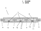
図1は本発明の実施の形態1における真空断熱材の平面図、図2は図1のА−А線断面の要部拡大図である。
(Embodiment 1)
FIG. 1 is a plan view of a vacuum heat insulating material according to
図1に示すように、真空断熱材6は直角二等辺三角形に成形された粉体の圧縮成形体からなる厚さ3mmの複数の芯材7を、ガスバリア性を有するラミネートフィルム8で覆い、ラミネートフィルム8の内部を減圧している。
As shown in FIG. 1, a vacuum
ここで、芯材7に使用する材料は、気相比率が90%前後の多孔体を板状に加工したものであればよく、工業的に利用できるものとして、粉体、発泡体および繊維体等があり、その使用用途や必要特性に応じて公知の材料を利用することができる。
Here, the material used for the
このうち、粉体としては、無機系、有機系、およびこれらの混合物があり、工業的には乾式シリカ、湿式シリカ、パーライト等を主成分とするものが利用できる。 Among these, as the powder, there are inorganic, organic, and mixtures thereof, and industrially, those mainly composed of dry silica, wet silica, pearlite and the like can be used.
発泡体としては、ウレタンフォーム、スチレンフォーム、フェノールフォーム等の連続気泡体が利用できる。 As the foam, open-cell bodies such as urethane foam, styrene foam, and phenol foam can be used.
また、繊維体としては、無機系、有機系、およびこれらの混合物があるが、断熱性能の観点から無機繊維が有利である。無機繊維としては、グラスウール、グラスファイバー、アルミナ繊維、シリカアルミナ繊維、シリカ繊維、ロックウール等の公知の材料を利用できる。 Moreover, as a fiber body, although there exist inorganic type, organic type, and these mixtures, an inorganic fiber is advantageous from a viewpoint of heat insulation performance. As the inorganic fiber, known materials such as glass wool, glass fiber, alumina fiber, silica alumina fiber, silica fiber, rock wool and the like can be used.
また、これらの発泡体、粉体、および繊維体等の混合物も利用することができる。 Moreover, mixtures of these foams, powders, fiber bodies and the like can also be used.
本実施の形態における真空断熱材6の芯材7の形状は直角二等辺三角形であるが、特に直角二等辺三角形である必要はなく、四角形、多角形、円形、L型、およびこれらの組み合わせからなる任意形状を選定できる。
The shape of the
図2に示すように、芯材7はラミネートフィルム8で覆われている。ラミネートフィルム8は熱溶着層9、ガスバリア層10、保護層11で構成されている。
As shown in FIG. 2, the
ここで、熱溶着層9は、加熱加圧されることでラミネートフィルム8の内部を減圧封止するものであり、低密度ポリエチレンフィルム、鎖状低密度ポリエチレンフィルム、高密度ポリエチレンフィルム、ポリプロピレンフィルム、ポリアクリロニトリルフィルム等、およびこれらの混合物を使用できる。
Here, the heat-
ガスバリア層10は、ラミネートフィルム8の表面を通じての芯材7への空気の侵入を防ぐものであり、金属箔または金属蒸着層を有するラミネートフィルムを使用できる。
The
保護層11は、ラミネートフィルム8の表面における埃や塵等による傷つきや、摩擦、折り曲げ、さらには芯材7の突き刺し等によるピンホールの発生を防ぐものであり、ナイロンフィルムやポリエチレンテレフタラートフィルム等が使用できる。
The
なお、本実施の形態ではラミネートフィルム8は熱溶着層9、ガスバリア層10、保護層11の構成としたが、三層以上の構成としてもよい。
In the present embodiment, the
ここでラミネートフィルム8の熱溶着層9は芯材7の側にくるよう配置されている。芯材7は一表面で、ラミネートフィルム8の上に固着されており、固着部12を有する。固着部12は、芯材7の表面の一部分にだけ形成されている。ただし、芯材7をラミネートフィルム8の上に固定するのに最低限の固着部の面積や強度は必要である。
Here, the heat-welded
なお、固着部12は芯材7の全面にわたり形成されていてもよい。
The fixing
本実施の形態における真空断熱材6は、芯材7をラミネートフィルム8の上に加熱加圧等の手段で固着させた後、ラミネートフィルム8で三辺シールの袋を形成し、袋の内部を減圧すべく真空排気を行い、所定圧力に到達した時、袋の開口部をシールすることで得ることができる
以上のように、本実施の形態における真空断熱材6は、芯材7がラミネートフィルム8の上に固着されているので、真空断熱材の製造時にわたり芯材の位置固定がされており、芯材の位置ずれがなく容易に真空断熱材を製造することが可能である。
In the vacuum
また、本実施の形態における真空断熱材6は固着部12が、芯材7の表面の一部分にだけ形成されているので、解体時に容易に芯材7とラミネートフィルム8を分離することができ、製品としてのリサイクル性を高めることができる。
Moreover, since the fixing | fixed
また、本実施の形態における真空断熱材6は複数個の芯材7により構成されるので、芯材間で折り曲げることができ、適用性が高まっている。
Moreover, since the vacuum
(実施の形態2)
図3は本発明の実施の形態2における真空断熱材の平面図である。図4は本発明の実施の形態2における真空断熱材の立体図である。
(Embodiment 2)
FIG. 3 is a plan view of the vacuum heat insulating material in
図3に示すように、真空断熱材13は五角形の芯材14と六角形の芯材15とで立体構造の展開図を形成するように配置させており、各芯材間には立体構造を形成するための折曲線16がある。
As shown in FIG. 3, the vacuum
図4の真空断熱材13は、図3に示す真空断熱材13を折曲線16で折り曲げて形成したものである。
The vacuum
なお、本実施の形態において芯材14が五角形で、芯材15が六角形としたが、芯材の形状の組み合わせは任意であり、様々な形状の芯材の組み合わせが可能であるので、芯材の間に位置する折曲線を自由に設計することができ、所望の立体構造を形成する真空断熱材を作製することができる。
In the present embodiment, the
(実施の形態3)
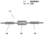
図5は本発明の実施の形態3における真空断熱材の断面図である。
(Embodiment 3)
FIG. 5 is a cross-sectional view of a vacuum heat insulating material according to
図5に示すように、本実施の形態における真空断熱材17の芯材18は厚み4mmでシリカ粉末を主成分とする材料から構成され、芯材19は厚み1mmでグラスウールを主成分とする材料から構成されている。
As shown in FIG. 5, the
以上のように、本実施の形態における真空断熱材17では、異なる厚みの芯材が共存しているので、本発明における真空断熱材17を適用する場合において、芯材19に対応する部分は、芯材18に対応する部分より省スペースな空間に真空断熱材17を適用することが可能となる。
As described above, in the vacuum
(実施の形態4)
図6は本発明の実施の形態4における真空断熱材の平面図である。図6において、真空断熱材20は実施の形態1における真空断熱材6と材料構成は同じとなっている。
(Embodiment 4)
FIG. 6 is a plan view of a vacuum heat insulating material according to
本実施の形態における真空断熱材20は、芯材7をラミネートフィルム8の上に加熱加圧等の手段で固着させた後、芯材7をガスバリア性のラミネートフィルム8で覆ったものをチャンバー内に設置、チャンバー内部を減圧し、所定の真空度に到達したときラミネートフィルム8を熱溶着してなる。
In the vacuum
熱溶着は面状のシリコンゴムヒーターでラミネートフィルム8の全面を上下から加熱することで行っており、ラミネートフィルム8は芯材7の存在しない箇所が全て熱溶着され、芯材7は各個が独立した空間内に配置されている。
Thermal welding is performed by heating the entire surface of the
以上のように、本実施の形態では、複数の芯材7がそれぞれ独立した空間内に位置することになるので、特定の芯材が入った空間の真空度が低下することが起きても、他の芯材が入った空間の真空度まで低下することがなく、断熱性能の低下を最小限に抑えることが可能となる。
As described above, in the present embodiment, since the plurality of
また、本実施の形態では、ラミネートフィルム8は芯材7の存在しない箇所が全て熱溶着されているので、真空断熱材端部のヒレ部を短くでき、真空断熱材表面における芯材部が占める面積部を大きくすることができ、有効断熱面積を大きくすることが可能である。
Moreover, in this Embodiment, since all the locations in which the
さらに芯材7の周縁部で切り取ることにより、真空断熱材を略芯材形状とすることができ、任意形状の真空断熱材を容易に形成することができる。
Furthermore, by cutting off at the peripheral part of the
以上のように、本発明にかかる真空断熱材は、芯材がラミネートフィルム上に固着されるので、製造時においても芯材を所定位置に固定でき、所望の真空断熱材を容易に得ることができる。 As described above, in the vacuum heat insulating material according to the present invention, since the core material is fixed on the laminate film, the core material can be fixed at a predetermined position even during production, and a desired vacuum heat insulating material can be easily obtained. it can.
特に、本発明にかかる真空断熱材は複数個の芯材で構成されるものに好適であり、複数個の芯材で構成される真空断熱材は折り曲げることも可能で、その適用性が高く、柔軟性を必要とするジャケット、コート等の防寒着のほか、ズボンや帽子、手袋、または寝具のふとんや座布団、カーテン等にも適用できる。 In particular, the vacuum heat insulating material according to the present invention is suitable for a material composed of a plurality of core materials, a vacuum heat insulating material composed of a plurality of core materials can be bent, and its applicability is high. In addition to winter clothes such as jackets and coats that require flexibility, it can also be applied to trousers, hats, gloves, bedding futons, cushions, curtains, and the like.
更に、本発明にかかる真空断熱材は、省エネルギーを必要とする保温保冷機器や、省スペースを必要とする情報機器、電子機器等にも適用できる。 Furthermore, the vacuum heat insulating material according to the present invention can also be applied to heat insulation and cold insulation equipment that requires energy saving, information equipment that requires space saving, electronic equipment, and the like.
6,13,17,20 真空断熱材
7,14,15,18,19 芯材
8 ラミネートフィルム
9 熱溶着層
12 固着部
6, 13, 17, 20 Vacuum
Claims (8)
Priority Applications (1)
| Application Number | Priority Date | Filing Date | Title |
|---|---|---|---|
| JP2004259194A JP2006077792A (en) | 2004-09-07 | 2004-09-07 | Vacuum insulating material |
Applications Claiming Priority (1)
| Application Number | Priority Date | Filing Date | Title |
|---|---|---|---|
| JP2004259194A JP2006077792A (en) | 2004-09-07 | 2004-09-07 | Vacuum insulating material |
Publications (1)
| Publication Number | Publication Date |
|---|---|
| JP2006077792A true JP2006077792A (en) | 2006-03-23 |
Family
ID=36157426
Family Applications (1)
| Application Number | Title | Priority Date | Filing Date |
|---|---|---|---|
| JP2004259194A Pending JP2006077792A (en) | 2004-09-07 | 2004-09-07 | Vacuum insulating material |
Country Status (1)
| Country | Link |
|---|---|
| JP (1) | JP2006077792A (en) |
Cited By (28)
| Publication number | Priority date | Publication date | Assignee | Title |
|---|---|---|---|---|
| JP2008082419A (en) * | 2006-09-27 | 2008-04-10 | Matsushita Electric Ind Co Ltd | Heat insulating panel, and floor heating system and refrigerator provided with the same |
| EP2910880A1 (en) * | 2014-02-24 | 2015-08-26 | Whirlpool Corporation | A folding approach to create a 3D vacuum insulated door from 2D flat vacuum insulation panels |
| US9689604B2 (en) | 2014-02-24 | 2017-06-27 | Whirlpool Corporation | Multi-section core vacuum insulation panels with hybrid barrier film envelope |
| US9752818B2 (en) | 2015-12-22 | 2017-09-05 | Whirlpool Corporation | Umbilical for pass through in vacuum insulated refrigerator structures |
| US9835369B2 (en) | 2012-04-02 | 2017-12-05 | Whirlpool Corporation | Vacuum insulated structure tubular cabinet construction |
| US9833942B2 (en) | 2012-04-11 | 2017-12-05 | Whirlpool Corporation | Method to create vacuum insulated cabinets for refrigerators |
| US9840042B2 (en) | 2015-12-22 | 2017-12-12 | Whirlpool Corporation | Adhesively secured vacuum insulated panels for refrigerators |
| US10018406B2 (en) | 2015-12-28 | 2018-07-10 | Whirlpool Corporation | Multi-layer gas barrier materials for vacuum insulated structure |
| US10030905B2 (en) | 2015-12-29 | 2018-07-24 | Whirlpool Corporation | Method of fabricating a vacuum insulated appliance structure |
| US10041724B2 (en) | 2015-12-08 | 2018-08-07 | Whirlpool Corporation | Methods for dispensing and compacting insulation materials into a vacuum sealed structure |
| US10052819B2 (en) | 2014-02-24 | 2018-08-21 | Whirlpool Corporation | Vacuum packaged 3D vacuum insulated door structure and method therefor using a tooling fixture |
| US10161669B2 (en) | 2015-03-05 | 2018-12-25 | Whirlpool Corporation | Attachment arrangement for vacuum insulated door |
| US10222116B2 (en) | 2015-12-08 | 2019-03-05 | Whirlpool Corporation | Method and apparatus for forming a vacuum insulated structure for an appliance having a pressing mechanism incorporated within an insulation delivery system |
| US10345031B2 (en) | 2015-07-01 | 2019-07-09 | Whirlpool Corporation | Split hybrid insulation structure for an appliance |
| US10365030B2 (en) | 2015-03-02 | 2019-07-30 | Whirlpool Corporation | 3D vacuum panel and a folding approach to create the 3D vacuum panel from a 2D vacuum panel of non-uniform thickness |
| US10422573B2 (en) | 2015-12-08 | 2019-09-24 | Whirlpool Corporation | Insulation structure for an appliance having a uniformly mixed multi-component insulation material, and a method for even distribution of material combinations therein |
| US10422569B2 (en) | 2015-12-21 | 2019-09-24 | Whirlpool Corporation | Vacuum insulated door construction |
| US10429125B2 (en) | 2015-12-08 | 2019-10-01 | Whirlpool Corporation | Insulation structure for an appliance having a uniformly mixed multi-component insulation material, and a method for even distribution of material combinations therein |
| US10598424B2 (en) | 2016-12-02 | 2020-03-24 | Whirlpool Corporation | Hinge support assembly |
| US10610985B2 (en) | 2015-12-28 | 2020-04-07 | Whirlpool Corporation | Multilayer barrier materials with PVD or plasma coating for vacuum insulated structure |
| US10712080B2 (en) | 2016-04-15 | 2020-07-14 | Whirlpool Corporation | Vacuum insulated refrigerator cabinet |
| US10731915B2 (en) | 2015-03-11 | 2020-08-04 | Whirlpool Corporation | Self-contained pantry box system for insertion into an appliance |
| US10807298B2 (en) | 2015-12-29 | 2020-10-20 | Whirlpool Corporation | Molded gas barrier parts for vacuum insulated structure |
| US10907888B2 (en) | 2018-06-25 | 2021-02-02 | Whirlpool Corporation | Hybrid pigmented hot stitched color liner system |
| US10907891B2 (en) | 2019-02-18 | 2021-02-02 | Whirlpool Corporation | Trim breaker for a structural cabinet that incorporates a structural glass contact surface |
| US11009284B2 (en) | 2016-04-15 | 2021-05-18 | Whirlpool Corporation | Vacuum insulated refrigerator structure with three dimensional characteristics |
| US11052579B2 (en) | 2015-12-08 | 2021-07-06 | Whirlpool Corporation | Method for preparing a densified insulation material for use in appliance insulated structure |
| US11752669B2 (en) | 2015-12-30 | 2023-09-12 | Whirlpool Corporation | Method of fabricating 3D vacuum insulated refrigerator structure having core material |
Citations (2)
| Publication number | Priority date | Publication date | Assignee | Title |
|---|---|---|---|---|
| JP2004197935A (en) * | 2002-12-05 | 2004-07-15 | Matsushita Refrig Co Ltd | Vacuum heat insulating material and its manufacturing method as well as outfit for protection against cold and personal computer using the same |
| JP2004239300A (en) * | 2003-02-04 | 2004-08-26 | Matsushita Refrig Co Ltd | Vacuum heat insulating material, method for manufacturing the same, note type personal computer using the vacuum heat insulating material, and printing device |
-
2004
- 2004-09-07 JP JP2004259194A patent/JP2006077792A/en active Pending
Patent Citations (2)
| Publication number | Priority date | Publication date | Assignee | Title |
|---|---|---|---|---|
| JP2004197935A (en) * | 2002-12-05 | 2004-07-15 | Matsushita Refrig Co Ltd | Vacuum heat insulating material and its manufacturing method as well as outfit for protection against cold and personal computer using the same |
| JP2004239300A (en) * | 2003-02-04 | 2004-08-26 | Matsushita Refrig Co Ltd | Vacuum heat insulating material, method for manufacturing the same, note type personal computer using the vacuum heat insulating material, and printing device |
Cited By (43)
| Publication number | Priority date | Publication date | Assignee | Title |
|---|---|---|---|---|
| JP2008082419A (en) * | 2006-09-27 | 2008-04-10 | Matsushita Electric Ind Co Ltd | Heat insulating panel, and floor heating system and refrigerator provided with the same |
| US10663217B2 (en) | 2012-04-02 | 2020-05-26 | Whirlpool Corporation | Vacuum insulated structure tubular cabinet construction |
| US9885516B2 (en) | 2012-04-02 | 2018-02-06 | Whirlpool Corporation | Vacuum insulated door structure and method for the creation thereof |
| US10697697B2 (en) | 2012-04-02 | 2020-06-30 | Whirlpool Corporation | Vacuum insulated door structure and method for the creation thereof |
| US9835369B2 (en) | 2012-04-02 | 2017-12-05 | Whirlpool Corporation | Vacuum insulated structure tubular cabinet construction |
| US10746458B2 (en) | 2012-04-02 | 2020-08-18 | Whirlpool Corporation | Method of making a folded vacuum insulated structure |
| US9874394B2 (en) | 2012-04-02 | 2018-01-23 | Whirlpool Corporation | Method of making a folded vacuum insulated structure |
| US10350817B2 (en) | 2012-04-11 | 2019-07-16 | Whirlpool Corporation | Method to create vacuum insulated cabinets for refrigerators |
| US9833942B2 (en) | 2012-04-11 | 2017-12-05 | Whirlpool Corporation | Method to create vacuum insulated cabinets for refrigerators |
| US9689604B2 (en) | 2014-02-24 | 2017-06-27 | Whirlpool Corporation | Multi-section core vacuum insulation panels with hybrid barrier film envelope |
| US9599392B2 (en) | 2014-02-24 | 2017-03-21 | Whirlpool Corporation | Folding approach to create a 3D vacuum insulated door from 2D flat vacuum insulation panels |
| US10052819B2 (en) | 2014-02-24 | 2018-08-21 | Whirlpool Corporation | Vacuum packaged 3D vacuum insulated door structure and method therefor using a tooling fixture |
| US10105931B2 (en) | 2014-02-24 | 2018-10-23 | Whirlpool Corporation | Multi-section core vacuum insulation panels with hybrid barrier film envelope |
| EP2910880A1 (en) * | 2014-02-24 | 2015-08-26 | Whirlpool Corporation | A folding approach to create a 3D vacuum insulated door from 2D flat vacuum insulation panels |
| US10365030B2 (en) | 2015-03-02 | 2019-07-30 | Whirlpool Corporation | 3D vacuum panel and a folding approach to create the 3D vacuum panel from a 2D vacuum panel of non-uniform thickness |
| US11713916B2 (en) | 2015-03-05 | 2023-08-01 | Whirlpool Corporation | Attachment arrangement for vacuum insulated door |
| US10161669B2 (en) | 2015-03-05 | 2018-12-25 | Whirlpool Corporation | Attachment arrangement for vacuum insulated door |
| US10731915B2 (en) | 2015-03-11 | 2020-08-04 | Whirlpool Corporation | Self-contained pantry box system for insertion into an appliance |
| US10345031B2 (en) | 2015-07-01 | 2019-07-09 | Whirlpool Corporation | Split hybrid insulation structure for an appliance |
| US10422573B2 (en) | 2015-12-08 | 2019-09-24 | Whirlpool Corporation | Insulation structure for an appliance having a uniformly mixed multi-component insulation material, and a method for even distribution of material combinations therein |
| US10429125B2 (en) | 2015-12-08 | 2019-10-01 | Whirlpool Corporation | Insulation structure for an appliance having a uniformly mixed multi-component insulation material, and a method for even distribution of material combinations therein |
| US11691318B2 (en) | 2015-12-08 | 2023-07-04 | Whirlpool Corporation | Method for preparing a densified insulation material for use in appliance insulated structure |
| US10222116B2 (en) | 2015-12-08 | 2019-03-05 | Whirlpool Corporation | Method and apparatus for forming a vacuum insulated structure for an appliance having a pressing mechanism incorporated within an insulation delivery system |
| US10041724B2 (en) | 2015-12-08 | 2018-08-07 | Whirlpool Corporation | Methods for dispensing and compacting insulation materials into a vacuum sealed structure |
| US11052579B2 (en) | 2015-12-08 | 2021-07-06 | Whirlpool Corporation | Method for preparing a densified insulation material for use in appliance insulated structure |
| US11009288B2 (en) | 2015-12-08 | 2021-05-18 | Whirlpool Corporation | Insulation structure for an appliance having a uniformly mixed multi-component insulation material, and a method for even distribution of material combinations therein |
| US10422569B2 (en) | 2015-12-21 | 2019-09-24 | Whirlpool Corporation | Vacuum insulated door construction |
| US10914505B2 (en) | 2015-12-21 | 2021-02-09 | Whirlpool Corporation | Vacuum insulated door construction |
| US9840042B2 (en) | 2015-12-22 | 2017-12-12 | Whirlpool Corporation | Adhesively secured vacuum insulated panels for refrigerators |
| US9752818B2 (en) | 2015-12-22 | 2017-09-05 | Whirlpool Corporation | Umbilical for pass through in vacuum insulated refrigerator structures |
| US10610985B2 (en) | 2015-12-28 | 2020-04-07 | Whirlpool Corporation | Multilayer barrier materials with PVD or plasma coating for vacuum insulated structure |
| US10018406B2 (en) | 2015-12-28 | 2018-07-10 | Whirlpool Corporation | Multi-layer gas barrier materials for vacuum insulated structure |
| US10514198B2 (en) | 2015-12-28 | 2019-12-24 | Whirlpool Corporation | Multi-layer gas barrier materials for vacuum insulated structure |
| US10807298B2 (en) | 2015-12-29 | 2020-10-20 | Whirlpool Corporation | Molded gas barrier parts for vacuum insulated structure |
| US10030905B2 (en) | 2015-12-29 | 2018-07-24 | Whirlpool Corporation | Method of fabricating a vacuum insulated appliance structure |
| US11577446B2 (en) | 2015-12-29 | 2023-02-14 | Whirlpool Corporation | Molded gas barrier parts for vacuum insulated structure |
| US11752669B2 (en) | 2015-12-30 | 2023-09-12 | Whirlpool Corporation | Method of fabricating 3D vacuum insulated refrigerator structure having core material |
| US11009284B2 (en) | 2016-04-15 | 2021-05-18 | Whirlpool Corporation | Vacuum insulated refrigerator structure with three dimensional characteristics |
| US10712080B2 (en) | 2016-04-15 | 2020-07-14 | Whirlpool Corporation | Vacuum insulated refrigerator cabinet |
| US11609037B2 (en) | 2016-04-15 | 2023-03-21 | Whirlpool Corporation | Vacuum insulated refrigerator structure with three dimensional characteristics |
| US10598424B2 (en) | 2016-12-02 | 2020-03-24 | Whirlpool Corporation | Hinge support assembly |
| US10907888B2 (en) | 2018-06-25 | 2021-02-02 | Whirlpool Corporation | Hybrid pigmented hot stitched color liner system |
| US10907891B2 (en) | 2019-02-18 | 2021-02-02 | Whirlpool Corporation | Trim breaker for a structural cabinet that incorporates a structural glass contact surface |
Similar Documents
| Publication | Publication Date | Title |
|---|---|---|
| JP2006077792A (en) | Vacuum insulating material | |
| JP3559035B2 (en) | Vacuum insulation material, method of manufacturing the same, and cold protection equipment and personal computer using vacuum insulation material | |
| JP5691112B2 (en) | Groove type vacuum heat insulating material and method for manufacturing the same | |
| JP4701882B2 (en) | Vacuum insulation | |
| JP4742605B2 (en) | Vacuum insulation material and manufacturing method thereof | |
| JP2004197954A (en) | Vacuum heat insulating material | |
| JP2007239288A (en) | Member for construction using vacuum insulating material | |
| JP2007138976A (en) | Vacuum heat insulating material and its manufacturing method | |
| JP4556746B2 (en) | Manufacturing method of vacuum insulation | |
| JP2006118634A (en) | Vacuum heat insulating material | |
| JP2008093933A (en) | Vacuum heat insulating material | |
| JP5848618B2 (en) | refrigerator | |
| JP6874529B2 (en) | Vacuum heat insulating material | |
| JP2006292063A (en) | Vacuum heat insulating material constitution | |
| JP2006316873A (en) | Vacuum heat insulating material | |
| JP4130982B2 (en) | Vacuum insulation | |
| JP2009138918A (en) | Thermal insulation member | |
| JP2004211905A (en) | Vacuum heat insulating material and outfit for protection against cold using it | |
| JPH09317044A (en) | Heat insulating material | |
| JP4654840B2 (en) | Vacuum insulation and composite insulation | |
| JP2010013840A (en) | House | |
| JP4742744B2 (en) | Vacuum insulation | |
| JP2007016928A (en) | Vacuum heat insulating material | |
| JP2007032779A (en) | Vacuum heat insulating material | |
| JP2006118635A (en) | Heat insulating material and floor heating system using heat insulating material |
Legal Events
| Date | Code | Title | Description |
|---|---|---|---|
| A621 | Written request for application examination |
Free format text: JAPANESE INTERMEDIATE CODE: A621 Effective date: 20070827 |
|
| RD01 | Notification of change of attorney |
Free format text: JAPANESE INTERMEDIATE CODE: A7421 Effective date: 20070912 |
|
| RD01 | Notification of change of attorney |
Free format text: JAPANESE INTERMEDIATE CODE: A7421 Effective date: 20091120 |
|
| A977 | Report on retrieval |
Free format text: JAPANESE INTERMEDIATE CODE: A971007 Effective date: 20091221 |
|
| A131 | Notification of reasons for refusal |
Free format text: JAPANESE INTERMEDIATE CODE: A131 Effective date: 20100309 |
|
| A521 | Written amendment |
Free format text: JAPANESE INTERMEDIATE CODE: A523 Effective date: 20100420 |
|
| A131 | Notification of reasons for refusal |
Free format text: JAPANESE INTERMEDIATE CODE: A131 Effective date: 20100914 |
|
| A02 | Decision of refusal |
Free format text: JAPANESE INTERMEDIATE CODE: A02 Effective date: 20110125 |