JP2006077493A - Laying structure of permeating water storage basin - Google Patents
Laying structure of permeating water storage basin Download PDFInfo
- Publication number
- JP2006077493A JP2006077493A JP2004263823A JP2004263823A JP2006077493A JP 2006077493 A JP2006077493 A JP 2006077493A JP 2004263823 A JP2004263823 A JP 2004263823A JP 2004263823 A JP2004263823 A JP 2004263823A JP 2006077493 A JP2006077493 A JP 2006077493A
- Authority
- JP
- Japan
- Prior art keywords
- water storage
- reservoir
- rainwater
- seepage
- laying structure
- Prior art date
- Legal status (The legal status is an assumption and is not a legal conclusion. Google has not performed a legal analysis and makes no representation as to the accuracy of the status listed.)
- Granted
Links
- XLYOFNOQVPJJNP-UHFFFAOYSA-N water Substances O XLYOFNOQVPJJNP-UHFFFAOYSA-N 0.000 title claims abstract description 164
- 230000035699 permeability Effects 0.000 claims abstract description 13
- 230000003204 osmotic effect Effects 0.000 claims description 22
- 239000004575 stone Substances 0.000 claims description 11
- 230000000149 penetrating effect Effects 0.000 claims description 8
- 230000008595 infiltration Effects 0.000 description 24
- 238000001764 infiltration Methods 0.000 description 24
- 239000012466 permeate Substances 0.000 description 13
- 239000004576 sand Substances 0.000 description 11
- 239000003673 groundwater Substances 0.000 description 4
- 238000009434 installation Methods 0.000 description 4
- 238000009412 basement excavation Methods 0.000 description 3
- 230000004048 modification Effects 0.000 description 3
- 238000012986 modification Methods 0.000 description 3
- XEEYBQQBJWHFJM-UHFFFAOYSA-N Iron Chemical compound [Fe] XEEYBQQBJWHFJM-UHFFFAOYSA-N 0.000 description 2
- 239000000463 material Substances 0.000 description 2
- 230000035515 penetration Effects 0.000 description 2
- 235000014676 Phragmites communis Nutrition 0.000 description 1
- 230000003247 decreasing effect Effects 0.000 description 1
- 238000010586 diagram Methods 0.000 description 1
- 239000000428 dust Substances 0.000 description 1
- 238000001914 filtration Methods 0.000 description 1
- 229910052742 iron Inorganic materials 0.000 description 1
- 239000010410 layer Substances 0.000 description 1
- 238000000034 method Methods 0.000 description 1
- 239000000047 product Substances 0.000 description 1
- 239000002689 soil Substances 0.000 description 1
- 239000002344 surface layer Substances 0.000 description 1
Images




Classifications
-
- Y—GENERAL TAGGING OF NEW TECHNOLOGICAL DEVELOPMENTS; GENERAL TAGGING OF CROSS-SECTIONAL TECHNOLOGIES SPANNING OVER SEVERAL SECTIONS OF THE IPC; TECHNICAL SUBJECTS COVERED BY FORMER USPC CROSS-REFERENCE ART COLLECTIONS [XRACs] AND DIGESTS
- Y02—TECHNOLOGIES OR APPLICATIONS FOR MITIGATION OR ADAPTATION AGAINST CLIMATE CHANGE
- Y02A—TECHNOLOGIES FOR ADAPTATION TO CLIMATE CHANGE
- Y02A20/00—Water conservation; Efficient water supply; Efficient water use
- Y02A20/40—Protecting water resources
Landscapes
- Sewage (AREA)
Abstract
Description
本発明は、道路の雨水を流す側溝の途中に設置される雨水桝等の集水桝の敷設構造に関するものであり、特に集水機能及び貯水機能を有し、かつ地中に浸透させる機能をも有する浸透貯水桝の敷設構造に関する。 The present invention relates to a structure for laying a drainage basin such as a rainwater basin installed in the middle of a gutter for flowing rainwater on a road, and in particular has a water collection function and a water storage function and has a function of penetrating into the ground. It also relates to the laying structure of the seepage reservoir.
従来、雨水の大半は地中に浸透して地下へ浸透し、河川や地下水へと流れていった。地中内の土砂は貯水機能を有するため、時間をかけて徐々に地下水として浸透していき、徐々に河川に流れていく。そのため、昔は地下水や河川の水量は安定して保たれていた。しかし、近年の都市開発によって地表が舗装化されるにつれて、雨水は側溝等の排水施設を通って直接に河川へ流されていくことが多くなった。すなわち、雨水は道路上を流れて側溝に集水され、側溝から集水桝を介して配水管を通って早いスピードで河川へ流れていく。そのため、地中による貯水機能は奪われ、地下水は減少し、河川の平常時流水量の減少を招くことになった。極端な場合には河川の水位が全くなくなってしまう地域さえ現れ始めている。その一方で大雨が降った場合には、大量の雨水が地中に浸透することなく一度に河川に流れ込むので河川の水量は短期間で急激に増加して、水位の急激な上昇を招き易く成っている。以上の事情から、舗装道路に降った雨水を一時的に貯水し、結果的に地中へ浸透させることができる排水施設が必要とされている。 Traditionally, most of the rainwater penetrated into the ground, penetrated underground, and flowed into rivers and groundwater. Since the soil in the ground has a water storage function, it gradually permeates as groundwater over time and gradually flows into the river. Therefore, in the past, the amount of groundwater and river water was kept stable. However, as the surface of the ground has been paved by recent urban development, rainwater has often flowed directly into rivers through drainage facilities such as ditches. In other words, rainwater flows on the road and is collected in the gutter, and then flows from the gutter to the river at a high speed through the drainage pipe through the catchment. As a result, the underground water storage function was deprived, groundwater decreased, and the normal amount of water flowed down the river. In extreme cases, even areas where the river water level is completely lost are beginning to appear. On the other hand, when heavy rain falls, a large amount of rainwater flows into the river all at once without penetrating into the ground, so the amount of water in the river increases rapidly in a short period of time, and the water level tends to rise rapidly. ing. In view of the above circumstances, there is a need for a drainage facility that can temporarily store rainwater that has fallen on a paved road and, as a result, penetrate into the ground.
そこで、従来から雨水が集水される集水桝に浸透機能をもたせ、地中に雨水を浸透させる雨水浸透桝が開発されてきた。例えば、図13に示すようなポーラスな壁面を有する四角筒形状の本体4と、該本体4の上端開口を塞ぐ蓋体5とからなる雨水浸透桝において、上記四角筒形状の本体4をその四角筒の軸芯を含む対角面で4分割した形状となる板状ブロック1の突き合わせにより構成した雨水浸透桝について提案されている。
Therefore, a rainwater infiltration trough has been developed that has a permeation function for collecting water from which rainwater is collected so that rainwater can penetrate into the ground. For example, in a rainwater infiltration trough comprising a rectangular tube-shaped
この雨水浸透桝の敷設構造は、簡単に説明すると、図14に示すように雨水桝の設置穴の掘削を行い、該掘削穴30の大きさに合わせて切断した透水シート31を掘削穴の周囲に付設し、続いて、掘削穴30の下部に砕石32を投入する。その上に雨水浸透桝を設置する。そして、設置した雨水浸透桝の本体と上記透水シート31との間隙に砕石36を投入して間隙を埋め、最後に表層を整地するというものである(以上、特許文献1参照)。
The laying structure of the rainwater infiltration basin will be described briefly. Excavation holes are excavated in the rainwater basin as shown in FIG. 14, and the
また、図15に示すように、雨水55を流す配水管路に配設され、雨水を地中に浸透させるための雨水浸透桝20であって、壁面部25に複数の第1貫通孔26が形成され、上部の開口部27に蓋28が取り付けられる桝本体29と、この桝本体の壁面部の少なくとも筒状部を囲って設けられ、前記壁面部の周囲にスペース30を形成するような形状を有し、かつ複数の第2の貫通孔31が形成されたスペース形成部材32と、このスペース形成部材を囲って設けられ雨水が透過可能な透水性シート材34とを備えた雨水浸透桝も開示されている。
Further, as shown in FIG. 15, a
この雨水浸透桝は、最初に雨水浸透桝20を設置するための大きめの穴45を堀り、この穴45の中に雨水浸透桝20を設置する。そして、いくつかの工程の後、穴45の内面と雨水浸透桝20との間の空間部に砂46を所定の高さ位置Bまで充填するという敷設構造をとる(以上特許文献2)。
In this rainwater infiltrating rod, a
これらの従来の集水桝は、集水桝に孔等を穿って浸透性を確保しているが、貯水機能は桝の外に埋められる砕石や砂によって得ていた。従って、集水桝自体に貯水機能を有するものではなかった。また、従来の雨水浸透桝は、周囲に貯水機能を持たせる必要があるため、砕石や土砂の間に一定の空隙を設けた状態で周囲を埋めなければならない。しかし、一定の空隙を設けた状態で埋めると強度を確保することができず実際としては非常に敷設が難しかった。
そこで、本発明は以上のような問題点を鑑みてなされたものであり、桝周囲に貯水機能を有した敷設をすることなく、雨水桝自体に浸透及び貯水機能を有した浸透貯水桝の敷設構造を提供することにある。 Therefore, the present invention has been made in view of the above problems, and laying of a seepage storage tank having a seepage and a storage function in a rainwater tank itself without laying a storage function around the fence. To provide a structure.
以上のような課題を解決するために、請求項1に記載された発明が採った手段は、道路に設置される浸透貯水桝100の敷設構造において、掘削された路面穴に、桝本体底面11の一部又は全体に底面開口部12が設けられてなる浸透貯水桝100を設置し、前記底面開口部12に、雨水浸透性かつ一定量の雨水貯水性を有する浸透貯水部材50を埋入してなることを特徴とする浸透貯水桝100の敷設構造、とするものである。
In order to solve the above-described problems, the means taken by the invention described in claim 1 is that, in the laying structure of the
本請求項1に記載された浸透貯水桝100の敷設構造は、雨水桝自体に雨水を貯水する機能及び浸透機能を付加したものである。そのため桝本体の底面に、雨水を貯水可能で、かつ浸透可能な浸透貯水部材50を埋入したものである。浸透貯水桝100の底面部において雨水を貯水でき、浸透させることができるのである。なお、本発明の浸透貯水桝100は、側面に雨水の浸透貯水機能を持たせてはいない。これは側面に雨水の浸透貯水機能を付与すると浸透貯水桝100の周囲にも浸透貯水機能を有するように土砂や砂利を埋設する必要がある。そうすると、これら埋設された土砂や砂利の間に空隙を設ける必要があるためこれら土砂等を押し固めることができず、浸透貯水桝100の周囲の土砂によって浸透貯水桝を完全に固定することができなくなってしまうからである。そこで、本発明の浸透貯水桝100は、底面側にのみ浸透機能を持たせて側面には浸透機能を持たせることなく、周囲の埋設される土砂の浸透性を必要とさせずに完全に固めることができるため安定して浸透貯水桝100を固定することができるのである。なお、浸透貯水桝100の底面にある浸透貯水部材50を埋入する底面開口部12の大きさや底面の厚さは特に限定するものではない。貯水機能を向上させたければ、底面開口部12を大きく、かつ底面を厚く設ければよい。
The laying structure of the
さらに、請求項2に記載された発明が採った手段は、道路に設置される浸透貯水桝100の敷設構造において、掘削された路面孔に、上面から下面まで貫通する通水孔41が設けられた第1ベース部40を設置し、該第1ベース部40に、底面の一部又は全体に底面開口部が設けられてなる桝本体10を設置し、該第1ベース部40の通水孔41又は/及び底面開口部に雨水浸透性かつ一定量の雨水貯水性を有する浸透貯水部材50を埋入してなることを特徴とする浸透貯水桝100の敷設構造、とするものである。
Further, according to the second aspect of the present invention, in the laying structure of the
請求項2に記載の浸透貯水桝100の敷設構造は、請求項1記載の桝本体10の底面に別体で作製された第1ベース部40を設置したものである。別体の第1ベース部40を設けることによって、路面孔の基礎部に桝本体10よりも広い面積で設置することができるため、桝本体10の載置状態を安定させることができる。また、底面部を別体に設けることで、様々な厚さや通水孔の大きさを有する第1ベース部40を用意しておくことができ、様々な浸透貯水性能を有する浸透貯水桝100を作製することができる。
The laying structure of the seepage
さらに、請求項3に記載された発明が採った手段は、道路に設置される浸透貯水桝100の敷設構造において、掘削された路面孔に、桝本体21底面の一部又は全体に底面開口部が設けられてなる下部貯水桝20を設置し、該下部貯水桝20に、桝本体底面の一部又は全体に底面開口部が設けられた上部集水桝30を設置し、前記下部貯水桝20の内側に雨水浸透性かつ一定量の雨水貯水性を有する浸透貯水部材50を埋入してなることを特徴とする浸透貯水桝100の敷設構造、とするものである。
Further, according to the third aspect of the present invention, in the laying structure of the
請求項3に記載された発明は、集水機能を有する桝と、貯水機能を有する桝とを分離したものである。すなわち、集水機能を上部集水桝30に集中し、貯水機能を下部貯水桝20に集中させたものである。上部集水桝30は、従来の雨水桝の機能を有するものであり、底面に下部貯水桝20を有し、そこに雨水を浸透させる機能を有する点以外は従来の桝と基本的には異なるところはない。下部貯水桝20は、内部を浸透貯水部材50で埋入されていて雨水の貯水機能及び浸透機能を有するものである。上部集水桝30に集水された雨水は、下部貯水桝20に流れ埋入された浸透貯水部材50によって、一定量貯水されて徐々に地中に浸透していくことになる。浸透しきれない雨水は、上部集水桝に設けられた従来と同様のオーバーフロー管を通して排水されていく。このように下方に貯水浸透機能を有する貯水桝を設置することで、従来であれば桝の外側に貯水浸透機能を有する埋設物を設置しなければならなかったのであるが、本発明は貯水桝内にそのような機能を有しているので、その必要はなくなる。勿論そのような埋設物を設置することを排除するものではない。
The invention described in claim 3 separates the ridge having a water collecting function and the ridge having a water storage function. That is, the water collecting function is concentrated on the upper water collecting
さらに、請求項4に記載された発明の採った手段は、下部貯水桝20の下方に、上面から下面まで貫通する通水孔41が設けられた第1ベース部40を設置してなることを特徴とする請求項3に記載の浸透貯水桝100の敷設構造、とするものである。
Furthermore, the means taken by the invention described in
本発明は、下部貯水桝20の底面に別体に作製された第1ベース部40を設けたものである。請求項2記載の発明と同様に、別体の第1ベース部40を設けることによって、基礎部に下部貯水桝20よりも広い面積で基礎部に載置することができるため浸透貯水桝100を安定させることができる。
In the present invention, the
さらに、請求項5に記載された発明の採った手段は、下部貯水桝20と上部集水桝30との間にそれぞれの桝を連結する第2ベース部45を設置してなることを特徴とする請求項3又は4に記載の浸透貯水桝100の敷設構造、とするものである。
Furthermore, the means taken by the invention described in claim 5 is characterized in that a
第2ベース部45は、下部貯水桝20と上部貯水桝30の連結部材としての機能を有するものである。このような連結部材を用いることにより、下部貯水桝20に容易に上部貯水桝30を載置することができる。
The
さらに、請求項6に記載された発明の採った手段は、浸透貯水部材50は、ポーラスコンクリート又は単粒度砕石からなることを特徴とする請求項1から5の何れかに記載の浸透貯水桝の敷設構造、とするものである。これは浸透貯水部材50として安価で、かつ貯水機能の優れるポーラスコンクリートや単粒度砕石を利用したものである。
Furthermore, the means taken by the invention described in claim 6 is that the osmotic
請求項1に記載の浸透貯水桝の敷設構造によれば、貯水桝の底面に底面開口部を設け、その底面開口部に浸透貯水部材を導入することによって、底面部に貯水機能を持たせることができるのと同時に、地中への浸透性をも確保することができる。しかも、地中に浸透していく雨水は、自然浸透であるのでその設置場所に応じて適量の雨水を浸透させることができる。 According to the laying structure of the seepage reservoir according to claim 1, the bottom portion is provided with a bottom opening, and the bottom portion is provided with a water storage function by introducing the seepage reservoir member into the bottom opening. At the same time, it can ensure penetration into the ground. Moreover, since rainwater that permeates into the ground is natural permeation, an appropriate amount of rainwater can be permeated according to the installation location.
請求項2に記載の浸透貯水桝の敷設構造によれば、第1ベース部を設けることによって、第1ベース部の厚さや開口部の大きさを適宜選択することができ、その場所に適合した浸透性及び貯水性を有した浸透貯水桝の設置構造とすることができる。 According to the laying structure of the seepage reservoir according to claim 2, by providing the first base portion, the thickness of the first base portion and the size of the opening can be appropriately selected and adapted to the place. It can be set as the installation structure of the osmotic water storage tank which has permeability and water storage.
請求項3に記載の浸透貯水桝の敷設構造によれば、上部桝に従来と同等若しくはそれ以上の十分なスペースを有する集水桝を形成させつつ、下部桝には十分な貯水機能を備えた桝を設けることができる。これにより従来のように桝周囲に貯水機能を有する埋設を行う必要がなくなる。 According to the laying structure of the seepage water storage tank according to claim 3, the water storage tank having sufficient space equal to or more than that of the conventional water tank is formed in the upper tank, and the lower tank has a sufficient water storage function. A fence can be provided. This eliminates the need to bury the water storage function around the ridge as in the prior art.
請求項4に記載の浸透貯水桝の敷設構造によれば、第1ベース部を設けることによって、安定した浸透貯水桝を敷設することができるようになる。また第1ベース部の厚さ及び開口部の大きさを選択することにより下部の貯水性を調整することができる。 According to the laying structure of the seepage reservoir according to the fourth aspect, the stable seepage reservoir can be laid by providing the first base portion. Moreover, the water storage of a lower part can be adjusted by selecting the thickness of a 1st base part, and the magnitude | size of an opening part.
請求項5に記載の浸透貯水桝の敷設構造によれば、下部貯水桝と上部集水桝との間に第第2ベース部を設置することにより、第2ベース部の形状によって上部集水桝を様々位置に配置することができる。そのため、その設置場所に応じて適切な位置に上部集水桝を備えた浸透貯水桝の敷設をおこなうことができる。 According to the laying structure of the seepage water reservoir according to claim 5, by installing the second base portion between the lower water reservoir and the upper water reservoir, the upper water reservoir according to the shape of the second base portion. Can be arranged in various positions. For this reason, it is possible to lay an infiltration reservoir having an upper catchment in an appropriate position according to the installation location.
請求項6に記載の浸透貯水桝の敷設構造によれば、浸透貯水部材にポーラスコンクリート及び単粒度砕石を用いることにより、容易かつ安価に貯水機能と浸透機能を持たせた浸透貯水部材を提供することができる。 According to the laying structure of the seepage water storage tank according to claim 6, by using porous concrete and single-grain crushed stone for the seepage water storage member, an seepage water storage member having a water storage function and a seepage function can be provided easily and inexpensively. be able to.
本発明の浸透貯水桝の敷設構造は、いわゆる雨水桝に雨水の十分な集水機能を確保しつつ、雨水の浸透機能及び貯水機能を付加したものである。本発明は、一つの桝で敷設したものと、二つの桝で敷設したものの2種類がある。便宜のため、前者を単独タイプ、後者を積み上げタイプとし各タイプに分け、実施例に従って本発明の浸透貯水桝の敷設構造について説明する。 The laying structure of the infiltration water storage tank of the present invention is a so-called rainwater tank with a rainwater infiltration function and a water storage function added while ensuring a sufficient rainwater collecting function. There are two types of the present invention, one laid with one fence and one laid with two fences. For the sake of convenience, the former is a single type and the latter is a stacked type.
(実施例1)
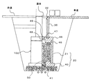
単独タイプの浸透貯水桝の敷設構造について説明する。図1には、実施例1の浸透貯水桝の右側のみ断面で表した一部断面図が示されている。図2には、実施例1に使用される浸透貯水桝の斜視図が示されている。まず、浸透貯水桝100について説明する。図2に示すように、浸透貯水桝100は周囲を壁面で囲われた略直方体に形成され、上端は蓋体が取り付けられるよう開口部11を有している。底面にも雨水を浸透させるため、四角形の底面開口部12を備えている。
Example 1
The laying structure of a single type seepage reservoir will be described. FIG. 1 is a partial cross-sectional view showing only the right side of the infiltration reservoir of Example 1 in cross section. FIG. 2 shows a perspective view of the seepage reservoir used in the first embodiment. First, the
次に、この浸透貯水桝100を用いた敷設構造について説明する。まず、浸透貯水桝100を敷設するために掘削された路面穴に浸透貯水桝100を設置する。このとき、図1のように基礎部110に砕石して基礎部を設けておいてもよいし、地中に直接載置してもよい。その後、底面開口部12に浸透貯水部材50を埋入する。浸透貯水部材50は、一定量の雨水を保水することができ、かつ雨水を浸透透過する機能を有する部材であれば、その素材を特に限定するものではない。好ましくはポーラスコンクリートや単粒度砕石を用いると雨水の浸透性が高く、かつ石の隙間に一定の雨水を貯水することができるため都合がよい。そして、通常の雨水桝と同様に雨水管やオーバーフロー管を接続した後、浸透貯水桝100の周囲を土砂で埋めて完成する。この場合、浸透貯水桝100の側面から雨水は浸透しないので、浸透貯水桝100を完全に固定できるように周囲の土砂を押し固めても構わない。
Next, a laying structure using the
以上のような浸透貯水桝100の敷設構造によれば、雨水は上端の開口部11や雨水管を介して浸透貯水桝100へ集められ、底面に設けられた浸透貯水部材50によって、一定量の雨水は一端貯水され、徐々に浸透貯水部材50を通って底面から地中に排水される。
According to the laying structure of the
この単独タイプの浸透貯水桝100の敷設構造は、いわゆる一般の雨水桝の底面部に雨水の浸透機能と貯水機能を付加したものである。底面部にこのような機能を設けたのは、雨水桝は側面に接続された配水管を通して雨水が集水されるものであるので、桝内部の空間は必ず確保する必要がある。従って、集水桝内部に浸透貯水部材50を投入することはできない。もし、集水桝内部に浸透貯水部材50を埋めれば水が溢れてしまうからである。そこで、本発明は集水桝の底面に底面開口部12を設けて、この底面開口部12に浸透性と貯水性を有する浸透貯水部材50を投入したのである。底面開口部12の大きさや深さを特に限定するものではなく、必要とする貯水量に応じて設定することができる。すなわち貯水量を多くしたいときは、大きく、深い底面開口部12を設ければよい。
This laying structure of the single-
(実施例2)
実施例2における浸透貯水桝100の敷設構造の一部断面図が図3に示されている。実施例2における浸透貯水桝100の桝本体10は、周囲を壁面で囲われた略直方体に形成され、上端は蓋体が取り付けられるよう開口部11を有している。底面は、雨水を浸透させるため全面が開口した底面開口部12を有している。
(Example 2)
FIG. 3 shows a partial cross-sectional view of the laying structure of the
第1ベース部40は、図4に示したように、矩形の平面板をなし中央に四角形の凸部42を備え、桝本体10の底面と嵌合することができる。さらに、その凸部の中央に開口した通水孔41が設けられている。
As shown in FIG. 4, the
以上の如く形成された桝本体10と第1ベース部40は、基礎部に第1ベース部40を敷設した後、その上面に桝本体10が載置され、全体で浸透貯水桝100を形成する。このような別体の第1ベース部40を設けることによって、様々な厚さのものや様々な大きさの通水孔41を備えたものを用意することができ、必要な排水処理量及び貯水処理量に応じて適宜選択して使用することができる。また、このように別体の第1ベース部40を用意しておけば、図5の第1ベース部のように、予め通水孔41に浸透貯水部材50を投入した製品を作製しておくことができるため、現場において通水孔41に浸透貯水部材50を埋設する工程を省くこともできる。
After the
こうして敷設された単独タイプの浸透貯水桝100の敷設構造によれば、底面部に設けられる浸透貯水部材層で一定量の雨水を貯水しつつ、かつその底面部から徐々に雨水が浸みだし適量の雨水が地中へ浸透していくことになる。このとき浸透しきれなかった雨水は、従来通り配水管を通って河川へと導かれることになる。
According to the laying structure of the single type
次に、積み上げタイプの浸透貯水桝の敷設構造について説明する。 Next, the laying structure of the stacked type seepage reservoir will be described.
(実施例3)
図6に本実施例における浸透貯水桝100の斜視図が示されている。図7には、本実施例の右側のみが断面で示された一部断面図が示されている。図12には、本実施例の使用状態が示されている。積み上げタイプの浸透貯水桝100は、図6、7に示すように、上方に設置される通常の雨水桝と同様の大きさを有する上部集水桝30と、その下に設置される上部集水桝30より大きく作製された下部貯水桝20とを備えている。下部貯水桝20は雨水の貯水機能を有するものであるので、多くの雨水を貯水することができるように上部集水桝30と比較して大きな容積を有しているのである。上部集水桝30は、実施例1と同様に周囲を壁面で囲われた略直方体に形成され、上端は蓋体が取り付けられるよう開口部32を有している。底面は雨水を通過させるため底面開口部が設けられている。下部貯水桝20の桝本体21も周囲を壁面で囲われた略直方体に形成され、底面に雨水を浸透させるための底面開口部が設けられている。
(Example 3)
FIG. 6 shows a perspective view of the
下部貯水桝20の下面には、第1ベース部40が設けられている。第1ベース部40は、下部貯水桝20を載置するために板状に形成されていて、下部貯水桝20を安定して固定するためのものである。基本的形状は実施例1に記載した図4と大きさが異なるだけで同様の形状である。また、第1ベース部40は、実施例1と同様に下部貯水桝20の内側の輪郭に沿うように上面内側が凸状に形成されており、第1ベース部40に下部貯水桝20を載置すると嵌合して固定することができる。第1ベース部40の凸部内には、下面と上面を貫通した通水孔41が設けられていて、この通水孔41にも浸透貯水部材50が埋入され浸透貯水機能を有するものとなる。なお、この第1ベースは必須なものではなく、底面に一体に設けてあってもよいし、底面に同様の機能を設けて第1ベース部を省略してもよい。
A
一方、上部集水桝30と下部貯水桝20との間には、第2ベース部45が設けられている。第2ベース部45は、下部貯水桝20の上に上部集水桝30を安定して載置するための連結部材としての機能をするものである。そのため図8に示すように第2ベース部45の下面には下部貯水桝20の上面開口と嵌合するように下面凸部46が設けられ、第2ベース部45の上面には、上部集水桝30の底面開口部23と嵌合するように上面凸部47が設けられている。上面凸部47は、上部集水桝30が下部貯水桝20と比較して小さく形成されているので、その載置位置に応じて上面凸部47が適切な位置、大きさに設けられる。例えば、上部集水桝30を中央に設置したい場合には、図8に示したように中央に上面凸部47が設けられる。また、辺部に設けたい場合には、図9に示したように中央から辺側に上面凸部47が設けられる。さらに、隅部に設けたい場合には、図10に示したように隅部に上面凸部47が設けられる。このように辺部や隅部に上部集水桝30を設ける理由は、例えば、図7において、歩道が私道であった場合に、中央に上部集水桝30を設けると下部貯水桝20が私道内に侵入してしまうからである。この場合辺や隅に設ければ、図11のように端に上部集水桝30が設けられることになるため、下部貯水桝20が私道側に侵入するのを防止することができる。さらに、第2ベース部45の内側に上部集水桝30と下部貯水桝20との間で雨水が通過することができるように通水孔48が形成されている。この通水孔48に上部集水桝30で集水された雨水に混じったゴミを下部貯水桝20に流すことがないように金網や細孔が設けられている鉄板などの濾過部材49を取り付けてもよい。なお、第2ベース部も必ずしも別体に形成する必要はなく、予め下部貯水桝20に第2ベース部と同様の形状のものを一体に形成しておいてもよい。
On the other hand, a
次に、以上のように形成された上部集水桝30、下部貯水桝20、第1ベース部40及び第2ベース部45を用いた浸透貯水桝100の敷設構造について説明する。まず、浸透貯水桝100を敷設するために掘削された路面穴に第1ベース部40を設置する。このとき図7のように基礎部に砕石を敷設しておいてもよい。その後、下部貯水桝20を第1ベース部40の凸部に嵌合するように設置した後、下部貯水桝20内に浸透貯水部材50を埋入する。その後、第2ベース部45の下面凸部46と下部貯水桝20の開口が嵌合するようにして下部貯水桝20に設置した後、上部集水桝30を第2ベース部45の上面凸部47に嵌合するように設置する。こうして浸透貯水桝100を完成させる。その後、雨水管やオーバーフロー管を上部集水桝30に接続し、浸透貯水桝100の周囲を土砂で埋めて完成する。この第3実施例においても、実施例1と同様に、浸透貯水桝100の側面は雨水の浸透性に影響しないので、完全に押し固めて構わない。設置された状態を示す参考図が図12に示されている。なお、第1ベース部40を省略し下部貯水桝を直接基礎部に設置するといった変形をおこなっても良いし、下部貯水桝に予め上部集水桝を設置できるように作製しておいて、第2ベース部45を省略しても構わない。
Next, the laying structure of the
こうして構築された浸透貯水桝100の敷設構造によれば、上部集水桝30は従来の雨水桝と同様の形態を有しているので、従来と同様の雨水を集水する機能を有する。一方で上部集水桝30の下方には、浸透貯水部材50が埋入された下部貯水桝20を有しているので、実施例1と比較して大量の雨水を貯水することができるとともに、余分な雨水は第1ベース部40の下面から地中に雨水を浸透させることができる。しかも雨水は自然落下によって浸透していくので、無理な排水をさせることがなく、自然に適合した量の雨水を浸透させることができるのである。
According to the laying structure of the
100 浸透貯水桝
11 開口部
20 下部貯水桝
21 桝本体
30 上部集水桝
40 第1ベース部
41 通水孔
45 第2ベース部
50 浸透貯水部材
100 Permeated
Claims (6)
掘削された路面穴に、桝本体底面の一部又は全体に底面開口部が設けられてなる浸透貯水桝を設置し、
前記底面開口部に、雨水浸透性かつ一定量の雨水貯水性を有する浸透貯水部材を埋入してなることを特徴とする浸透貯水桝の敷設構造 In the laying structure of seepage reservoirs installed on the road,
In the excavated road surface hole, install a seepage reservoir with a bottom opening provided in part or all of the bottom surface of the main body,
An osmotic water storage laying structure characterized in that a permeable water storage member having rainwater permeability and a certain amount of rainwater storage capacity is embedded in the bottom opening.
掘削された路面孔に、上面から下面まで貫通する通水孔が設けられた第1ベース部を設置し、
該第1ベース部に、底面の一部又は全体に底面開口部が設けられてなる桝本体を設置し、
該第1ベース部の通水孔又は/及び底面開口部に雨水浸透性かつ一定量の雨水貯水性を有する浸透貯水部材を埋入してなることを特徴とする浸透貯水桝の敷設構造。 In the laying structure of seepage reservoirs installed on the road,
In the excavated road surface hole, a first base part provided with a water passage hole penetrating from the upper surface to the lower surface is installed,
In the first base portion, a heel body having a bottom surface opening provided on a part or the whole of the bottom surface is installed,
An osmotic water storage laying structure, characterized in that a permeable water storage member having rainwater permeability and a certain amount of rainwater water storage is embedded in a water passage hole or / and a bottom opening of the first base portion.
掘削された路面孔に、桝本体底面の一部又は全体に底面開口部が設けられてなる下部貯水桝を設置し、
該下部貯水桝に、桝本体底面の一部又は全体に底面開口部が設けられた上部集水桝を設置し、
前記下部貯水桝の内側に雨水浸透性かつ一定量の雨水貯水性を有する浸透貯水部材を埋入してなることを特徴とする浸透貯水桝の敷設構造。 In the laying structure of seepage reservoirs installed on the road,
In the excavated road surface hole, install a lower water storage basin with a bottom surface opening partly or entirely on the bottom surface of the main body,
In the lower reservoir, install an upper catchment basin having a bottom surface opening partly or entirely on the bottom surface of the main body,
An osmotic reservoir laying structure characterized in that a permeable reservoir member having rainwater permeability and a certain amount of rainwater reservoir is embedded inside the lower reservoir.
The osmotic water storage member laying structure according to any one of claims 1 to 5, wherein the osmotic water storage member is made of porous concrete or single-grain crushed stone.
Priority Applications (1)
| Application Number | Priority Date | Filing Date | Title |
|---|---|---|---|
| JP2004263823A JP3876374B2 (en) | 2004-09-10 | 2004-09-10 | Construction structure of seepage reservoir |
Applications Claiming Priority (1)
| Application Number | Priority Date | Filing Date | Title |
|---|---|---|---|
| JP2004263823A JP3876374B2 (en) | 2004-09-10 | 2004-09-10 | Construction structure of seepage reservoir |
Publications (2)
| Publication Number | Publication Date |
|---|---|
| JP2006077493A true JP2006077493A (en) | 2006-03-23 |
| JP3876374B2 JP3876374B2 (en) | 2007-01-31 |
Family
ID=36157169
Family Applications (1)
| Application Number | Title | Priority Date | Filing Date |
|---|---|---|---|
| JP2004263823A Expired - Fee Related JP3876374B2 (en) | 2004-09-10 | 2004-09-10 | Construction structure of seepage reservoir |
Country Status (1)
| Country | Link |
|---|---|
| JP (1) | JP3876374B2 (en) |
Cited By (1)
| Publication number | Priority date | Publication date | Assignee | Title |
|---|---|---|---|---|
| JP2022092307A (en) * | 2020-12-10 | 2022-06-22 | 株式会社フクユー緑地 | Drainage structure and construction method of drainage structure |
-
2004
- 2004-09-10 JP JP2004263823A patent/JP3876374B2/en not_active Expired - Fee Related
Cited By (2)
| Publication number | Priority date | Publication date | Assignee | Title |
|---|---|---|---|---|
| JP2022092307A (en) * | 2020-12-10 | 2022-06-22 | 株式会社フクユー緑地 | Drainage structure and construction method of drainage structure |
| JP7576248B2 (en) | 2020-12-10 | 2024-10-31 | 株式会社フクユー緑地 | Drainage structure and construction method of drainage structure |
Also Published As
| Publication number | Publication date |
|---|---|
| JP3876374B2 (en) | 2007-01-31 |
Similar Documents
| Publication | Publication Date | Title |
|---|---|---|
| JP2009127359A (en) | Drainage structure of gutter | |
| JP5346731B2 (en) | Rainwater penetration facilities | |
| JP2011074563A (en) | Rainwater infiltration system | |
| JP4772662B2 (en) | Osmosis system and construction method thereof | |
| KR20120021802A (en) | Method and structure for getting underground water | |
| CN218713130U (en) | Prevent drainage structures on massif landslide | |
| JPH08260553A (en) | Side ditch structure for infiltrating water | |
| JP3876374B2 (en) | Construction structure of seepage reservoir | |
| KR100379624B1 (en) | Construction method for water storage facilities keeping stable water storage level and preventing floation in underground | |
| JPH10168985A (en) | Structure for promoting infiltration of surface water | |
| JP7429922B2 (en) | storage system | |
| JP2662823B2 (en) | Rainwater penetration structure | |
| JP2014084647A (en) | Drainage system and drainage method | |
| JP3182036U (en) | Permeation side groove | |
| JPH09111814A (en) | Water storage facility | |
| KR101218752B1 (en) | Appraratus for storing and infiltrating rain water | |
| JPH11152785A (en) | Infiltration, facility having water-retention structure | |
| KR100621364B1 (en) | Collection device and construction method of the collection device | |
| JP2007239424A (en) | Overflow infiltration and drainage block construction | |
| JPH1161953A (en) | Rainwater storage seepage tank | |
| JP2562066Y2 (en) | Structure of rainwater storage and infiltration facility | |
| KR200364453Y1 (en) | Knocked-down Double filter Stone-filled drainage, rainwater pipe | |
| JPH0649890A (en) | Structure of underground storage permeation laying | |
| JP2007092293A (en) | Burial structure of manhole conduit | |
| JPH0841956A (en) | Drain infiltrating structure |
Legal Events
| Date | Code | Title | Description |
|---|---|---|---|
| A131 | Notification of reasons for refusal |
Free format text: JAPANESE INTERMEDIATE CODE: A131 Effective date: 20060529 |
|
| A521 | Written amendment |
Free format text: JAPANESE INTERMEDIATE CODE: A523 Effective date: 20060728 |
|
| TRDD | Decision of grant or rejection written | ||
| A01 | Written decision to grant a patent or to grant a registration (utility model) |
Free format text: JAPANESE INTERMEDIATE CODE: A01 Effective date: 20060925 |
|
| A61 | First payment of annual fees (during grant procedure) |
Free format text: JAPANESE INTERMEDIATE CODE: A61 Effective date: 20061017 |
|
| R150 | Certificate of patent or registration of utility model |
Free format text: JAPANESE INTERMEDIATE CODE: R150 |
|
| FPAY | Renewal fee payment (event date is renewal date of database) |
Free format text: PAYMENT UNTIL: 20121110 Year of fee payment: 6 |
|
| S533 | Written request for registration of change of name |
Free format text: JAPANESE INTERMEDIATE CODE: R313533 |
|
| FPAY | Renewal fee payment (event date is renewal date of database) |
Free format text: PAYMENT UNTIL: 20121110 Year of fee payment: 6 |
|
| R350 | Written notification of registration of transfer |
Free format text: JAPANESE INTERMEDIATE CODE: R350 |
|
| FPAY | Renewal fee payment (event date is renewal date of database) |
Free format text: PAYMENT UNTIL: 20151110 Year of fee payment: 9 |
|
| R250 | Receipt of annual fees |
Free format text: JAPANESE INTERMEDIATE CODE: R250 |
|
| LAPS | Cancellation because of no payment of annual fees |