JP2006050163A - Image pickup device - Google Patents
Image pickup device Download PDFInfo
- Publication number
- JP2006050163A JP2006050163A JP2004227211A JP2004227211A JP2006050163A JP 2006050163 A JP2006050163 A JP 2006050163A JP 2004227211 A JP2004227211 A JP 2004227211A JP 2004227211 A JP2004227211 A JP 2004227211A JP 2006050163 A JP2006050163 A JP 2006050163A
- Authority
- JP
- Japan
- Prior art keywords
- image
- data
- information
- unit
- recording
- Prior art date
- Legal status (The legal status is an assumption and is not a legal conclusion. Google has not performed a legal analysis and makes no representation as to the accuracy of the status listed.)
- Pending
Links
Images


Abstract
Description
本発明は、撮像装置、より詳しくは、動画データを複数のブロックに分割して記録し得るようになされた撮像装置に関する。 The present invention relates to an imaging apparatus, and more particularly, to an imaging apparatus configured to be able to divide and record moving image data into a plurality of blocks.
従来から、頭部に装着して映像を観察する表示装置や、頭部に装着して撮影する撮影装置や、あるいはこれらの両方の機能を備えた装置が知られている。 2. Description of the Related Art Conventionally, a display device that is worn on the head and observes an image, a photographing device that is worn on the head and shoots, or a device that has both functions is known.
例えば特開平7−240889号公報に記載の頭部装着型表示装置は、TVカメラ装置により撮影している映像を、頭部に装着した表示装置に表示して、観察しながら撮影を行うことができるとともに、該TVカメラ装置に設けられた制御スイッチを操作することにより、上記表示装置を介した外界光の選択的な取り入れを、必要に応じて行うことができるものとなっている。 For example, a head-mounted display device described in Japanese Patent Laid-Open No. 7-240889 can display an image captured by a TV camera device on a display device mounted on the head and perform imaging while observing the image. In addition, by operating a control switch provided in the TV camera device, it is possible to selectively take in external light through the display device as necessary.
また、特開平11−164186号公報に記載の画像記録装置は、眼鏡型のフレームに撮像部等を設けて、撮像部の撮影レンズが撮影者と同じ方向を向くようにすることで、撮影者の視線と同じ方向の被写体を撮影することができるようにしたものとなっている。さらに、この特開平11−164186号公報には、光透過性を有するケーシング部分を備えたゴーグル型のパーソナル液晶プロジェクタに撮像部を設けることにより、該撮像部により撮影した画像を外界光による被写体に重畳して表示する技術が記載されている。
しかしながら、上記特開平7−240889号公報に記載のものでは、撮影時には、撮影画像を表示装置で観察しながら撮影する操作に専念しなければならないために、例えば、運動会や祭りなどの各種イベントを撮影する場合に、実際の被写体を直接観察するのと異なって自らイベントを楽しむことができず、たいへん負担になっていた。また、閉じた空間で長時間電子的な映像を観察していると、眼で直接見る場合の自然な観察と異なって、疲労を感じることがあるというのは経験的な事実である。 However, in the thing of the said Unexamined-Japanese-Patent No. 7-240889, since it must concentrate on the operation | movement which image | photographs, observing a picked-up image with a display apparatus at the time of imaging | photography, for example, various events, such as a sports day and a festival Unlike direct observation of actual subjects, it was not easy to enjoy the event on its own, which was a heavy burden. Moreover, it is an empirical fact that, when observing electronic images for a long time in a closed space, fatigue may be felt, unlike natural observation when viewing directly with eyes.
また、上記特開平11−164186号公報に記載のものでは、眼鏡型のフレームに撮影部を設けただけでは、被写体を観察するのと、撮影範囲を認識するのとを同時に行うことはできず、一旦、被写体から目を離して別体で設けられたカメラ本体側の画像表示部を確認しなければならない。一方、パーソナル液晶プロジェクタに撮像部を設けた構成では、表示される画像と、透過されてくる被写体と、を同時に視野内に入れることは可能であるが、撮影時には表示される画像の方に意識を集中することになるために、やはり撮影者自身がイベント等を楽しむのは難しい。 Further, in the device described in Japanese Patent Application Laid-Open No. 11-164186, it is not possible to observe the subject and recognize the photographing range at the same time only by providing the photographing unit on the glasses-type frame. Once the eye is away from the subject, the image display unit on the camera body side provided separately must be confirmed. On the other hand, in a configuration in which an image pickup unit is provided in a personal liquid crystal projector, it is possible to put a displayed image and a transmitted subject in the field of view at the same time. It is difficult for photographers themselves to enjoy events and the like.
こうして、上述したような技術では、撮影を行う際に撮影者以外の者と同様の自然な行動をとることは困難であり、撮影動作に拘束されたり撮影の負担を感じたりしていた。 Thus, with the above-described technology, it is difficult to take natural actions similar to those other than the photographer when taking a picture, and it is restricted by the shooting operation or feels a burden of taking a picture.
また、従来の技術では、頭部に装着する装置とそれ以外の装置とを、ケーブルを用いて接続していたために、携帯する際にケーブルが絡まったり、移動する際にケーブルが邪魔になるなどの不便があった。 In addition, in the conventional technology, a device attached to the head and other devices are connected using a cable, so that the cable becomes tangled when carrying it, or the cable becomes an obstacle when moving. There was inconvenience.
本発明は上記事情に鑑みてなされたものであり、負担を感じることなく簡単に撮影を行い得る、携帯に便利で機動性に優れた撮像装置を提供することを目的としている。 The present invention has been made in view of the above circumstances, and an object of the present invention is to provide an imaging device that is easy to carry and excellent in mobility, which can easily perform shooting without feeling a burden.
上記の目的を達成するために、第1の発明による撮像装置は、動画データを複数のブロックに分割して記録するとともに上記動画データの再生順序を示す動画再生プログラムチェーン情報と上記それぞれのブロックの動画データが撮影された時刻からの相対的な経過時間とを記録する動画データ記録手段と、編集前の上記動画データと同時に検出された情報であって該動画データを編集するための生体情報と上記生体情報が検出された時刻からの相対的な経過時間を検出するための情報とを記録する生体情報記録手段と、を具備したものである。 In order to achieve the above object, an image pickup apparatus according to a first invention records moving image data divided into a plurality of blocks and records moving image reproduction program chain information indicating the reproduction order of the moving image data and each of the blocks. Moving image data recording means for recording a relative elapsed time from the time when the moving image data was shot, and information detected at the same time as the moving image data before editing, and biometric information for editing the moving image data; Biometric information recording means for recording information for detecting a relative elapsed time from the time when the biometric information was detected.
また、第2の発明による撮像装置は、上記第1の発明による撮像装置において、上記動画データが、撮影者の頭部に装着された状態のカメラにより撮影して得られたものである。 An image pickup apparatus according to a second aspect of the invention is the image pickup apparatus according to the first aspect of the invention, wherein the moving image data is obtained by photographing with a camera mounted on a photographer's head.
さらに、第3の発明による撮像装置は、上記第1の発明による撮像装置において、上記生体情報が、撮影者の頭部の角速度に係る角速度情報を含む。 Furthermore, an imaging device according to a third invention is the imaging device according to the first invention, wherein the biological information includes angular velocity information relating to an angular velocity of a photographer's head.
第4の発明による撮像装置は、上記第3の発明による撮像装置において、上記角速度情報に基づいて上記動画データに対して行われる編集処理が、記録された画像データの、カッティングと、ぶれ補正と、記録時間の引き延ばしと、電子ズーミングと、の内の少なくとも1つを含む。 An image pickup apparatus according to a fourth invention is the image pickup apparatus according to the third invention, wherein the editing process performed on the moving image data based on the angular velocity information includes cutting and blur correction of recorded image data. , Including at least one of extending recording time and electronic zooming.
第5の発明による撮像装置は、上記第1の発明による撮像装置において、上記生体情報が、撮影者の視線方向に係る視線方向情報を含む。 An imaging device according to a fifth invention is the imaging device according to the first invention, wherein the biological information includes gaze direction information related to a gaze direction of the photographer.
第6の発明による撮像装置は、上記第5の発明による撮像装置において、上記視線方向情報に基づいて上記動画データに対して行われる編集処理が、記録された画像データの電子ズーミングを含む。 An image pickup apparatus according to a sixth invention is the image pickup apparatus according to the fifth invention, wherein the editing process performed on the moving image data based on the line-of-sight direction information includes electronic zooming of recorded image data.
第7の発明による撮像装置は、上記第6の発明による撮像装置において、上記視線方向情報は、視線方向の移動速度と、視線方向の連続的な移動量と、の少なくとも一方を含む情報である。 An image pickup apparatus according to a seventh invention is the image pickup apparatus according to the sixth invention, wherein the line-of-sight direction information is information including at least one of a movement speed in the line-of-sight direction and a continuous movement amount in the line-of-sight direction. .
本発明の撮像装置によれば、携帯に便利で機動性に優れていて、負担を感じることなく簡単に撮影を行うことが可能となる。 According to the imaging apparatus of the present invention, it is convenient to carry and excellent in mobility, and it is possible to easily shoot without feeling a burden.
以下、図面を参照して本発明の実施例を説明する。 Embodiments of the present invention will be described below with reference to the drawings.
図1から図72は本発明の実施例1を示したものであり、図1は画像システムの使用形態を示す斜視図である。 1 to 72 show a first embodiment of the present invention, and FIG. 1 is a perspective view showing a usage form of an image system.
この画像システム1は、図1に示すように、略めがね型をなし画像を撮像する機能を備えた頭部装着部2と、この頭部装着部2に対して無線で通信を行うことにより該頭部装着部2に係る操作入力を遠隔で行うとともに該頭部装着部2により撮像された画像データを無線で受信して記録し編集する機能を備えた画像記録/編集装置4と、に大別される。
As shown in FIG. 1, the
該画像システム1は、静止画像や動画像を撮像する機能を備えたものであるために、撮像装置を兼ねたものとなっている。
Since the
上記頭部装着部2は、シースルー表示時に観察対象である被写体を実質的に直接観察することが可能であるとともに、該被写体の撮像も行うことができるように構成されたものである。この頭部装着部2は、形状が略めがね型をなすことで分かるように、視度補正用の一般的な眼鏡とほぼ同様にして頭部に装着し用いるものとなっており、重量やサイズ等も通常の眼鏡に極力近似するように小型軽量化が図られている。
The head-mounted
上記画像記録/編集装置4は、撮像のための各種操作信号を上記頭部装着部2へ無線で送信するとともに、該頭部装着部2により撮像された画像を無線で受信して記録を行い、さらに記録後の画像を編集し得るように構成されたものである。この画像記録/編集装置4には、後述するような第2操作スイッチ171(図11および図5参照)が設けられていて、この第2操作スイッチ171は、上記頭部装着部2のシースルー表示の制御や撮影動作の制御などの比較的頻繁に行われる操作を、撮影者が遠隔操作により手元で行うためのものである。従って、この画像記録/編集装置4は、例えば片手の掌に収まる程度の小型な大きさとなるように、可能な範囲内での小型軽量化が図られたものとなっている。また、この画像記録/編集装置4は、腰のベルト等に取り付けた状態、あるいは上着の内ポケット等に収納した状態、などの各種の状態でも使用することができるように構成されている。
The image recording /
これらの頭部装着部2と画像記録/編集装置4とは、本実施例では互いに別体として構成されており、これにより、頭部装着部2を小型軽量化することによる装着感の向上、画像記録/編集装置4の採用による操作性の向上、などを図るようにしている。
The
さらに、頭部装着部2と画像記録/編集装置4とは、上述したように、無線で通信するようになっているために、例えば互いにケーブルで接続したときのような取り回しの不便さや拘束感がなく、自由で軽快に操作することができる。頭部に装着して用いる装置は、高い機動性や操作性が要求されるために、このような構成を採用することが特に有効となっている。
Furthermore, since the head-mounted
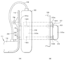
次に、図2から図4を参照して、頭部装着部2の外観および概要について説明する。図2は頭部装着部2を示す正面図、図3は頭部装着部2を示す平面図、図4は頭部装着部2を示す右側面図である。
Next, with reference to FIGS. 2 to 4, the appearance and outline of the
この頭部装着部2は、一般的な眼鏡におけるレンズ、リム、ブリッジ、智などに相当する部分であるフロント部11と、このフロント部11の左右両側から後方(被写体と反対側)に向けて各延設されており該フロント部11に対して折り畳み可能となっているテンプル部12と、を有して構成されている。
The
上記フロント部11は、画像表示用の光学系の一部や視線方向検出用の光学系の一部や電気回路等を内蔵する保持手段たるフレーム部13を有して構成されている。
The
このフレーム部13は、略中央部に被写体までの距離を測定するために用いられる測距手段たる投光用発光部16が、左右両側部に被写体側からの音声をステレオで収録するための第1マイク17および第2マイク18が、それぞれ設けられている。
The
さらに、上記フレーム部13には、左右両眼に各対応するように導光部材たる透明光学部材14,15が取り付けられている。これらの透明光学部材14,15の内の、一方である透明光学部材14は公知の視線方向を検出するために用いられ、他方である透明光学部材15は画像を表示するために用いられるようになっている。そして、これらの透明光学部材14,15は、それぞれの機能を果たすために必要な最小限の大きさとなるように形成されている。
Further, transparent
上記透明光学部材14には、HOE(Holographic Optical Element:ホログラフィー光学素子)24とハーフミラー128とHOE129とがそれぞれ配設されており、上記透明光学部材15にはコンバイナとしてのHOE25が配設されている。
The transparent
加えて、上記フレーム部13には、上記透明光学部材14,15の被写体側に位置するように、視度調整のためのレンズ21,22がそれぞれ着脱可能に取り付けられるようになっている。
In addition,
すなわち、フレーム部13には、上記レンズ21,22を取り付けるための取付手段たるリム20が、例えば中央側と、左眼の左横側と、右眼の右横側と、でそれぞれビス28により取り付けられるようになっている。
That is, a
このリム20には、鼻梁を左右から支持することにより、鼻梁に対してこの頭部装着部2を載置するための一対の鼻パッド19が、一対のクリングス23を介して設けられている。
The
このような構成において、上記ビス28を外すことにより、リム20およびレンズ21,22を容易に取り外すことができるようになっており、また、レンズ21,22を他の視度に対応するものに交換して、再び取り付けることも容易となっている。
In such a configuration, the
このとき、リム20を所定以上の弾力性のある素材により形成すれば、1つのビス28を外すかまたは緩めるだけで、左眼用のレンズ21または右眼用のレンズ22の一方のみを選択的に(独立して)着脱することができて利便性が高まる。
At this time, if the
さらに、フレーム部13の左眼側(つまり、図2や図3における右側)の側面の継手29には、被写体像を撮像するための撮像手段であり測距手段も兼ねたカメラである撮像部30が、台座33を介して、撮影方向を調節可能に固定されるようになっている。
Further, the joint 29 on the side surface of the left side of the frame unit 13 (that is, the right side in FIGS. 2 and 3) is an imaging unit that is an imaging unit for imaging a subject image and also serves as a ranging unit. 30 is fixed via a
この台座33は、ビス34,35により上記継手29に対して取り付けられ、ビス36,37を介して自己の上に上記撮像部30を取り付けるように構成されている。該台座33を介して、撮像部30の上記フロント部11に対する相対的な角度を調整することにより、後述するように、該撮像部30に含まれる撮影光学系31(図10等も参照)の光軸と視軸とを調整することができるようになっている。
The
そして、上記撮像部30の背面側からは、ケーブル38が一旦延出されて、左眼側のテンプル部12の下側を潜った後に、上記フレーム部13に接続されている。これにより、フレーム部13内の電気回路と、撮像部30内の電気回路とが互いに接続されている。
A
上記テンプル部12は、丁番78,79を用いて上記フロント部11と接続されていて、これにより該フロント部11に対して折り畳み可能となっている。すなわち、非使用時には、テンプル部12をフロント部11の中央部に向けて折り曲げ、該フロント部11に沿って折り畳まれた位置を取らせることができるために、小型化して収納や運搬を便利に行うことが可能となっている。また、左右の各テンプル部12の先端部には、耳にかけるための先セルモダン26がそれぞれ設けられている。
The
右眼側のテンプル部12には、後述する角速度センサなどのこの頭部装着部2に係る各種の電子回路の一部と、この頭部装着部2内の各回路へ電源を供給するための電源回路の構成要素である着脱可能な電池と、を収納するための収納部27が設けられている。この収納部27の上面には、当該頭部装着部2による表示をオン/オフするためのスイッチ39が配設されている。そして、該収納部27からは、ケーブル27aが延設されて、上記フレーム部13内の各回路に接続されており、さらには上記撮像部30内の回路を介して、上記画像記録/編集装置4の回路と接続されるようになっている。
The
次に、図5から図9を参照して、画像記録/編集装置4の外観および概要について説明する。図5は操作パネルを閉じた状態の画像記録/編集装置4を示す平面図、図6は操作パネルを閉じた状態の画像記録/編集装置4を示す右側面図、図7は操作パネルを閉じた状態の画像記録/編集装置4を示す左側面図、図8は操作パネルに配置された操作スイッチ類を示す平面図、図9は操作パネルを開いた状態の画像記録/編集装置4を示す斜視図である。
Next, the appearance and outline of the image recording /
この画像記録/編集装置4は、本体部41と、この本体部41に対してヒンジ43を介して開閉自在に設けられた操作パネル42と、を有して構成されている。
The image recording /
上記本体部41は、後述するような各回路を内蔵するとともに、上記操作パネル42を開いたときに観察可能となる位置に液晶モニタとして構成された表示手段であるLCD表示素子(以下、「LCD」と省略する。)48が配設されたものとなっている。このLCD48は、再生時に画像を表示するのに用いられる他に、各種のモードを設定するためのメニュー画面等の表示にも用いられるようになっている。
The
この本体部41の上面側には、図5に示すように、上記操作パネル42が閉じ状態であっても操作可能な辺縁角部に電源スイッチ44が配設され、さらに、該操作パネル42を開閉する際に指先等を掛け易いように、凹部45が形成されている。
On the upper surface side of the
また、この本体部41の右側面には、図6に示すように、ヒンジ46により該本体部41に対して開閉自在となる蓋52が設けられており、該蓋52の係止部52aを本体部41側の被係止部52bに係止させることで、閉じ状態が保たれるようになっている。この蓋52を開くと、該図6に示すように、電源を供給するためのバッテリを着脱自在に挿入するためのバッテリ挿入口55と、テレビと接続するための端子であるAV/S接続端子50と、パーソナルコンピュータ(PC)と接続するための端子であるPC接続端子51と、が露呈する。このように、コード類は、本体部41の右側面において、まとめて接続されるようになっており、他の面からコード類が延出することがなく、コードを取り回すときの煩わしさを軽減することができるようになっている。
Further, as shown in FIG. 6, a
一方、本体部41の左側面にも、図7に示すように、ヒンジ47により該本体部41に対して開閉自在となる蓋53が設けられており、該蓋53の係止部53aを本体部41側の被係止部53bに係止させることで、閉じ状態が保たれるようになっている。この蓋53を開くと、該図7に示すように、着脱式の記録媒体であるディスク249(図11参照)を挿入するためのディスク挿入口54が露呈するようになっている。
On the other hand, as shown in FIG. 7, a
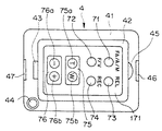
上記操作パネル42は、閉じた状態でも操作可能に露呈する外面側に図5に示すように比較的操作される頻度の高いスイッチ類が配設されていて、さらに、開いた状態でのみ操作可能に露呈する内面側に図8に示すように比較的操作される頻度の低い操作スイッチ類が配置されている。
The
すなわち、上記操作パネル42の外面側には、上記第2操作スイッチ171が配設されている。この第2操作スイッチ171は、図5に示すように、FA/A/Mスイッチ71と、F/Vスイッチ72と、レリーズスイッチ(REL)73と、録画スイッチ(REC)74と、ズームスイッチ75と、露出補正スイッチ76と、を有して構成されている。これらのスイッチ類は、上述したように、撮影動作の際に変更する頻度が比較的高い情報を設定するためのスイッチ類である。
That is, the
上記FA/A/Mスイッチ71は、切換手段であって、所定の焦点距離以上の望遠撮影時に撮影範囲を示す撮影画枠に対応する撮影画像を拡大して電子ビューとしてシースルー表示する動作を、全自動(FA:フルオートモード)で行うか、自動(A:オートモード)で行うか、手動(M:マニュアルモード)で行うか、を切り替えるためものである。上記フルオートモードは、ビデオデータとともに生体情報としての角速度データや視線方向データを記録するモードとなっており、このフルオートモードで記録されたデータが本実施例で説明する画像編集の対象となる。
The FA / A /
上記F/Vスイッチ72は、切換手段であって、上記透明光学部材15におけるシースルー表示を、撮影範囲を示す撮影画枠(F)にするか、あるいは撮像部30からの撮影画像(V)(電子ビュー)にするか、を切り替えるためのものである。
The F /
上記レリーズスイッチ(REL)73は、動画に比して高精細な静止画の撮影を開始するためのものである。 The release switch (REL) 73 is for starting to capture a still image with higher definition than a moving image.
上記録画スイッチ(REC)74は、動画の録画開始と録画停止とを押される毎に切り替えるためのものである。 The recording switch (REC) 74 is for switching each time a moving image recording start and a recording stop are pressed.
上記ズームスイッチ75は、撮影画枠設定手段であって、上記撮影光学系31を含む撮像部30のズーム(光学ズームおよび/または電子ズーム)を、望遠(T:テレ)側に行うためのテレスイッチ75aと、広角(W:ワイド)側に行うためのワイドスイッチ75bと、を含んで構成されている。
The
上記露出補正スイッチ76は、撮影される画像の露出補正をマイナス側に行うためのマイナス露出補正スイッチ76aと、該露出補正をプラス側に行うためのプラス露出補正スイッチ76bと、を含んで構成されている。
The
なお、上記撮影光学系31のズーム動作と、観察者でもある撮影者から観察する撮影画枠の視角の変更と、は連動して行われるように構成されているために、上記ズームスイッチ75は、撮影者から観察する撮影画枠の視角を縮小するためのテレスイッチ75aと、該視角を拡大するためのワイドスイッチ75bと、を有するものであると言い換えることもできる。
Since the zoom operation of the photographic
また、「撮影画枠」とは、上記撮像部30により撮影される被写体の範囲を表す指標である。
The “photographing image frame” is an index representing the range of the subject photographed by the
一方、上記操作パネル42の内面側には、音声を再生するためのスピーカ56と、このスピーカ56から発生される音声のボリュームを大きくするためのスイッチ57と、該ボリュームを小さくするためのスイッチ58と、記録媒体としてのディスク249に記録された画像情報を再生したり一時停止したりするための再生/停止スイッチ59と、画像を逆方向に早送りしてサーチするためのスイッチ61と、画像を順方向に早送りしてサーチするためのスイッチ62と、画像システム1に係る各種の機能や日付などを設定したり、画像編集のための各種操作情報を設定するためのメニュー画面を上記LCD48に表示するためのメニューボタン63と、該メニュー画面に表示されている各項目の内の着目項目を上、下、左、右の各方向へ移動したり表示情報をスクロールしたりするためのメニュー選択スイッチ66,67,68,69と、表示されている着目項目等を確定するための確定スイッチ65と、が配設されている。これらのスイッチ類は、上述したように、撮影動作の際に変更する頻度が比較的低い情報を設定するためのスイッチ類である。
On the other hand, on the inner surface side of the
図10は頭部装着部2の主として電子回路に係る構成を示すブロック図である。
FIG. 10 is a block diagram showing a configuration mainly related to an electronic circuit of the
この画像システム1の構成は、上述したように、撮像機能を有する頭部装着部2と、この頭部装着部2および自己に係る各種操作入力を受けて制御を行うとともに該頭部装着部2により撮影された画像を記録し編集する機能を備えた画像記録/編集装置4(図11)とに大別される。これらの内でも上記頭部装着部2は、さらに、撮像を行うための撮像手段たる撮像部30と、主としてシースルー表示を行うための表示手段であるシースルー画像表示部6と、撮影者の視線方向を検出したり撮影者の頭部の動きに伴う角速度を検出したりするための視線方向/角速度検出部7と、画像記録/編集装置4と無線により信号の授受を行うための受信手段であり送信手段たる通信部8と、当該頭部装着部2内の各回路に電源を供給するための電源回路174と、に分けられる。これら撮像部30とシースルー画像表示部6と視線方向/角速度検出部7とは、何れも、上記通信部8を介して、上記画像記録/編集装置4と通信するようになっている。また、電源回路174は、電池を有して構成されており、この電池は、上述したように、上記収納部27(図2参照)に対して着脱可能に取り付けられるようになっている。
As described above, the configuration of the
上記シースルー画像表示部6は、LEDドライバ112と、LED113と、集光レンズ114と、LCD115と、LCDドライバ117と、HOE116と、HOE25と、投光用LED16aと、LEDドライバ118と、集光レンズ16bと、上記スイッチ39と、第4CPU111と、を有して構成されている。このシースルー画像表示部6は、本実施例においては、観察者の片方の眼(ここでは、具体例として右眼)側にのみ配設されている。従って、観察者は、シースルー画像を、該片眼側のみで観察するようになっている。
The see-through
上記LEDドライバ112は、上記第4CPU111の制御に基づき上記LED113を発光させるものである。
The
上記LED113は、発光源であって投影手段を構成するものであり、上記LEDドライバ112により駆動されて光を発光するようになっている。このLED113は、例えば、R(赤),G(緑),B(青)の3色の光をそれぞれ発光可能なダイオードを含んで構成されている。
The
上記集光レンズ114は、上記投影手段を構成するものであって、このLED113により発光された光を集光するものである。
The condensing
上記LCD115は、上記投影手段を構成するものであって、上記撮影画枠や撮影された映像などを表示するためのものであり、上記集光レンズ114を介したLED113の光により背面側から照明される透過型の液晶表示手段となっている。
The
上記LCDドライバ117は、上記第4CPU111の制御に基づいて、LCD115を駆動して撮影画枠等を表示させるものであり、後述するようなパララックスを補正するための補正手段も兼ねている。
The
上記HOE116は、上記LCD115を介して射出される光を、後述するように収差を補正しながら鉛直下方(図13、図14参照)へ向けて反射する反射光学部材である。
The
上記HOE25は、反射型コンバイナとしての機能を果たすものであり、上記HOE116からの光を撮影者の眼へ向けて反射し回折させることにより、上記LCD115に表示された撮影画枠等を観察可能に投影するとともに、外界光を撮影者の眼へ向けて透過させ得るように構成されたコンバイナである。なお、この実施例1のHOE25は、最小限の大きさとなるように構成された上記透明光学部材15に合わせて、同様に、最小限の大きさとなるように構成されている。
The
上記投光用LED16aは、上記測距を行うための上記投光用発光部16に含まれていて、測距用の光を発光する発光源である。
The light projecting LED 16a is included in the light projecting
上記集光レンズ16bは、上記投光用LED16aにより発光された測距用の光を、被写体に向けて投影するためのものである。 The condensing lens 16b is for projecting the distance measuring light emitted from the light projecting LED 16a toward the subject.
上記LEDドライバ118は、上記第4CPU111の制御に基づいて、上記投光用LED16aを駆動するためのものである。
The
上記スイッチ39は、上記第4CPU111に接続されていて、該スイッチ39が閉じたことが第4CPU111により検出されると、該第4CPU111がこのシースルー画像表示部6の表示を禁止するようになっている。この画像システム1は、撮影動作にとらわれることなく通常の行動をしながら撮影することが可能となるように構成されたものであるために、例えば、歩行時や車の運転時にも使用してしまいがちである。しかし、撮影者がこのような状態にあるときにシースルー表示がされると、その表示に気をとられることもあり得る。従って、これを未然に防止するために、スイッチ39を設けて、シースルー表示を禁止することができるようにしている。なお、このときには表示は禁止されるが、撮影自体は継続することが可能となっている。
The
上記第4CPU111は、制御手段であって、このシースルー画像表示部6内の各回路を制御するものであり、上記撮像部30の後述する第3CPU103と双方向に接続されて連携を取りながら、制御動作を行うようになっている。
The
このようなシースルー画像表示部6の作用は、ほぼ次のようになっている。
The operation of the see-through
第4CPU111は、LEDドライバ112を介してLED113を発光させる。
The
LED113から発光された光は、集光レンズ114により集光されて、LCD115を背面から照明する。
The light emitted from the
LED113は、撮影画枠を表示する場合には、上記R(赤),G(緑),B(青)の3色の光を発光させるダイオードの内の、例えばG(緑)のダイオードのみを発光させる。
The
第4CPU111が撮影範囲を示す撮影画枠に対応する信号を生成してLCDドライバ117へ転送するとともに、発光を行わせる制御信号をLEDドライバ112へ転送すると、LCDドライバ117が、該信号に基づきLCD115を駆動して撮影画枠を表示面上に表示させるとともに、LED113が発光して該LCD115を背面側から照明する。
When the
こうして照明されたLCD115から投影される上記撮影画枠の映像は、収差を補正されながらHOE116により鉛直下方に反射され、HOE25に投影される。
The image of the photographic image frame projected from the
HOE25は、上記HOE116からの光線を、撮影者の眼へ向けて反射する。これにより、撮影者は、撮影範囲を示す撮影画枠を虚像として観察することができる。
The
一方、測距を行う場合には、第4CPU111が、測距用の発光を行わせる制御信号をLEDドライバ118へ転送する。
On the other hand, in the case of performing distance measurement, the
LEDドライバ118は、上記制御信号を受けると、投光用LED16aを発光させる。この投光用LED16aにより発光された測距用の光は、上記集光レンズ16bにより平行光に変換されて、被写体へ向けて投光される。
Upon receiving the control signal, the
こうして投光された照明光は、被写体により反射され、該反射光が上記撮像部30により受光されて、後述するように測距演算が行われることになる。
The illumination light thus projected is reflected by the subject, the reflected light is received by the
次に、上記視線方向/角速度検出部7は、上記シースルー画像表示部6が配設されているのとは反対側の片眼(ここでは、具体例として左眼)側に配設されるようになっている。この視線方向/角速度検出部7は、視線方向検出装置として機能する視線方向検出部と、角速度検出装置として機能する角速度検出部と、に大別される。
Next, the line-of-sight direction / angular
上記視線方向検出部は、LEDドライバ124と、LED125と、集光レンズ126と、反射ミラー127と、ハーフミラー128と、HOE24と、HOE129と、反射ミラー131と、結像レンズ132と、バンドパスフィルタ133と、CCD134と、CCDドライバ135と、CDS/AGC回路136と、A/D変換回路137と、TG138と、を有して構成されている。これらの内のLEDドライバ124、LED125、集光レンズ126、反射ミラー127、およびHOE24は、観察者の眼へ赤外平行光束を投光するための赤外光投影手段たる投光系を構成している。また、上述した内のHOE24、ハーフミラー128、HOE129、反射ミラー131、結像レンズ132、バンドパスフィルタ133、およびCCD134は、観察者の眼から反射された光束を受光するための受光系を構成している。
The line-of-sight direction detection unit includes an LED driver 124, an
また、上記角速度検出部は、角速度センサ141,142と、増幅器143,144と、A/D変換回路145と、を有して構成されている。
The angular velocity detection unit includes
そして、これら視線方向検出部と角速度検出部とを含む視線方向/角速度検出部7全体を制御するためのものとして、第2CPU121が設けられている。
The
上記LEDドライバ124は、上記第2CPU121の制御に基づいて、上記LED125を駆動するためのものである。
The LED driver 124 is for driving the
上記LED125は、LEDドライバ124により駆動されて、視線方向検出用の赤外光を発光する赤外発光ダイオードである。
The
上記集光レンズ126は、LED125により発光された赤外光を、平行光束に変換するものである。
The condensing
上記反射ミラー127は、集光レンズ126により平行光束に変換された赤外光を、鉛直下方(図20、図21参照)へ向けて反射する反射光学部材である。
The
上記ハーフミラー128は、上記反射ミラー127からの赤外光を上記HOE24側へ透過させると共に、該HOE24からの光を水平方向へ反射するものである。
The
上記HOE24は、ハーフミラー128を透過してきた赤外光を観察者の眼へ向けて反射するとともに、該観察者の眼からの光を該ハーフミラー128へ向けて反射するものである。なお、この実施例1のHOE24は、最小限の大きさとなるように構成された上記透明光学部材14に合わせて、同様に、最小限の大きさとなるように構成されている。このHOE24は、赤外域における狭い所定の帯域についての波長選択性を有しており、選択された帯域の赤外光のみについては高い反射特性を示す一方で、それ以外の波長の光線に対しては高い透過特性を示すものとなっている。このようにHOE24は、上記シースルー画像表示部6のHOE25とは全く異なる帯域の波長選択機能を有するものであるが、全体的な視感透過特性(あるいは、平均的な視感透過特性)については該HOE25とほぼ同様となっている。このように、左右の眼に対して平均的に同様の視感透過特性を有する光学素子を配置することにより、違和感を感じることがなく、かつ長時間使用しても眼の疲れを少なくすることができる。
The
上記HOE129は、上記HOE24とハーフミラー128とにより導かれた観察者の眼からの光束を、鉛直上方へ向けて反射するものある。このHOE129は、上記HOE24と同じ波長選択性を有するものとなっている。従って、このHOE129を介することにより、観察者の眼側から入射する光束の内の、上記所定の帯域に含まれる赤外光以外の波長の光線をカットする(つまり、反射することなく透過してしまう。)ことができるようになっている。こうして、後述するようなプルキンエ像を、他の波長域の光線によるノイズの影響を軽減しながら、より高い精度で検出することが可能となっている。なお、光学素子としてHOE129を用いることにより、波長選択性が高まるという利点があるだけでなく、赤外光以外に対して透過性を有しているために、透明光学部材14内に配設しても目立ち難いという利点もある。
The
上記反射ミラー131は、上記HOE129からの光束を水平方向に反射するものである。
The
上記結像レンズ132は、上記反射ミラー131により反射された光束を、上記CCD134の撮像面上に結像するためのものである。
The
上記バンドパスフィルタ133は、上記結像レンズ132により結像される光束の内の、上記所定の帯域の赤外光のみを透過するものである。上述したように、上記HOE129により既に帯域の制限が行われているが、該HOE129を透明光学部材14内に配置した場合には、さらに他の可視光等が混入する可能性があるために、このバンドパスフィルタ133により再度帯域の制限を行うようにしている。こうして、CCD134の前面側にバンドパスフィルタ133を設けることにより、外光ノイズによる影響をさらに軽減することが可能となっている。
The
上記CCD134は、二次元の光電変換手段であって、撮像面が2次元となった撮像素子として構成されており、上述したように結像された観察者の眼の像を光電変換して、電気信号として出力するものである。このCCD134の出力に基づいて、プルキンエ像の位置と瞳孔中心の位置とが後述するように求められ、これらの相対的な位置関係に基づいて視線方向が算出されるようになっている。
The
上記CCDドライバ135は、上記第2CPU121の制御に基づいて、上記CCD134を駆動するためのものである。
The
上記CDS/AGC回路136は、上記CCD134から出力される映像信号に、ノイズ除去や増幅の処理を行うものである。
The CDS /
上記TG138は、上記第2CPU121の制御に基づいて、上記CCDドライバ135と、上記CDS/AGC回路136とへ、連係して動作を行わせるためのタイミング信号をそれぞれ供給するものである。
The
上記A/D変換回路137は、上記CDS/AGC回路136から出力されるアナログの映像信号をデジタルの映像信号に変換するものである。このA/D変換回路137により変換されたデジタルの映像信号は、上記撮像部30の後述する通信制御部173へ出力されるようになっている。
The A /
上記角速度センサ141,142は、上述したように収納部27内に格納されており、互いに独立した方向(例えばヨー方向とピッチ方向)の角速度を検出するためのものである。
The
上記増幅器143,144は、上記角速度センサ141,142の出力をそれぞれ増幅するためのものである。
The
上記A/D変換回路145は、上記増幅器143,144によりそれぞれ増幅された角速度センサ141,142からのアナログ信号を、デジタルデータへそれぞれ変換するものである。このA/D変換回路145により変換されたデジタルデータは、上記第2CPU121へ出力されるようになっている。
The A /
上記第2CPU121は、制御手段であって、この視線方向/角速度検出部7内の各回路を制御するものであり、上記撮像部30の後述する第3CPU103と双方向に接続されて連携を取りながら、制御動作を行うようになっている。この第2CPU121は、メモリとして機能するRAM122と、時間を計測するためのタイマ123と、を内部に有して構成されている。
The
このような視線方向/角速度検出部7の動作原理や作用等については、後で他の図面を参照して説明する。
The operation principle, action, and the like of the line-of-sight direction / angular
上記撮像部30は、撮影光学系31と、ローパスフィルタ86と、CCD87と、CDS/AGC回路88と、A/D変換回路89と、TG(タイミングジェネレータ)90と、CCDドライバ91と、USMドライバ95と、絞りシャッタドライバ96と、AE処理回路97と、AF処理回路98と、上記第1マイク17と、上記第2マイク18と、増幅回路99と、増幅回路100と、A/D変換回路101と、EEPROM102と、メモリ104と、第3CPU103と、を有して構成されている。
The
上記撮影光学系31は、光学的な被写体像を結像するためのものであり、焦点距離可変なズーム光学系として構成されている。
The photographing
上記ローパスフィルタ86は、この撮影光学系31を通過した光束から不要な高周波成分を取り除くためのものである。
The low-
CCD87は、撮像素子であって、このローパスフィルタ86を介して上記撮影光学系31により結像された光学的な被写体像を電気的な信号に変換して出力するものである。
The
上記CDS/AGC回路88は、信号処理手段であって、このCCD87から出力される信号に後述するようなノイズ除去や増幅の処理を行うものである。
The CDS /
上記A/D変換回路89は、信号処理手段であって、このCDS/AGC回路88から出力されるアナログの画像信号をデジタルの画像信号に変換するものである。
The A /
上記メモリ104は、このA/D変換回路89から出力されるデジタルの画像信号を一時的に記憶するためのものである。
The
上記CCDドライバ91は、上記CCD87を制御して駆動するためのものである。
The
上記TG(タイミングジェネレータ)90は、上記CDS/AGC回路88,A/D変換回路89,CCDドライバ91に、タイミングを制御するための信号をそれぞれ供給するものである。このTG90は、上記視線方向/角速度検出部7の第2CPU121と双方向に接続されて、制御されるようになっている。
The TG (timing generator) 90 supplies signals for controlling the timing to the CDS /
上記USMドライバ95は、上記撮影光学系31に含まれる後述するUSM(Ultra Sonic Motor:超音波モータ)92,93,94を選択的に駆動するための駆動回路である。このUSMドライバ95も、上記視線方向/角速度検出部7の第2CPU121により制御されるようになっている。
The
上記絞りシャッタドライバ96は、上記撮影光学系31に含まれる後述する絞りシャッタ84を制御して駆動するための駆動回路である。この絞りシャッタドライバ96は、上記視線方向/角速度検出部7の第2CPU121により制御されるようになっている。
The
上記AE処理回路97は、上記A/D変換回路89の出力に基づいて、露出制御用の算出を行うオート露出処理回路であり、演算結果を上記第3CPU103へ出力するようになっている。
The
上記AF処理回路98は、上記A/D変換回路89の出力に基づいて、オートフォーカス(AF)制御用の算出を行うオートフォーカス処理回路であり、演算結果を上記第3CPU103へ出力するものである。
The AF processing circuit 98 is an autofocus processing circuit that performs calculation for autofocus (AF) control based on the output of the A /
上記第1マイク17および第2マイク18は、上述したように、被写体側からの音声をステレオで収録するためのものである。
The
上記増幅回路99および増幅回路100は、上記第1マイク17および第2マイク18から入力された音声信号をそれぞれ増幅するためのものである。
The
上記A/D変換回路101は、上記増幅回路99および増幅回路100によりそれぞれ増幅されたアナログの音声信号をデジタルの音声信号に変換して上記第3CPU103へ出力するものである。
The A /
上記EEPROM102は、露出制御やオートフォーカス処理等のための各種補正データが画像システム製造時に記録されたものである。このEEPROM102に記録されたデータは、上記第3CPU103により読み出されるようになっている。
The
上記第3CPU103は、この撮像部30内の各回路を制御するための制御手段であり、上記シースルー画像表示部6の第4CPU111や、上記視角方向/角速度検出部7の第2CPU121と連携を取りながら制御動作を行うようになっている。さらに、この第3CPU103は、上記画像記録/編集装置4の後述する第1CPU161と双方向に通信を行って制御されるようになっている。
The
上記撮影光学系31は、さらに詳しくは、フロントレンズ81と、バリエータレンズ82と、コンペンセータレンズ83と、絞りシャッタ84と、フォーカスレンズ85と、USM92,93,94と、を有して構成されている。
More specifically, the photographing
上記フロントレンズ81は、撮影光学系31に含まれる複数のレンズの中で最も被写体側に位置するものである。
The
上記バリエータレンズ82は、この撮影光学系31の焦点距離を変更するためのものである。
The
上記コンペンセータレンズ83は、上記バリエータレンズ82により撮影光学系31の焦点距離を変化させるのに伴うピント位置のずれを、補正するためのものである。
The
上記絞りシャッタ84は、撮影光学系31を通過する光束の通過範囲を規定するための絞りの機能と、該光束の通過時間を規定するためのシャッタの機能と、を兼用するものである。
The
上記フォーカスレンズ85は、この撮影光学系31のピントを調整するためのものであり、ピントが調整されたときには、上記CCD87に被写体像が合焦して結像される。
The
上記USM92,93,94は、上記バリエータレンズ82,コンペンセータレンズ83,フォーカスレンズ85をそれぞれ駆動するための駆動源である。
The
上記通信部8は、通信制御部173と、送受信部172と、を有して構成されている。
The
上記通信制御部173は、フレーム同期(時分割多重方式でフレーム単位に同期をとること。)と、フレームの構成要素であるスロット(このスロットは、属性と属性値のペアを含んで構成されている。)のデータフォーマット処理と、を行うものである。
The
上記送受信部172は、無線送受信用のアンテナや、送信するデジタル信号をアンテナ発信用のアナログ信号に変換したり該アンテナを介して受信した信号をデジタル信号に変換したりするモデムなどを有して構成されている。
The transmission /
このような通信部8の送受信時の動作は次のようになっている。
The operation of the
上記通信制御部173の受信側は、送受信部172のモデムから供給される受信データから、所定のタイミングで1スロット分のデータを取り出す。そして、該通信制御部173の受信側は、このデータの中から同期信号を抽出して、フレーム同期信号を生成し、スクランブル等を解除する。その後、通信制御部173の受信側は、画像記録/編集装置4から送信された、各種の操作信号、あるいは、ディスク249(図11参照)に記録された画像データ、を第3CPU103へ送出する。
The reception side of the
また、上記通信制御部173の送信側は、上記A/D変換回路89からメモリ104を介して出力される映像信号と、上記視角方向/角速度検出部7のA/D変換回路137から出力される撮影者の眼に係る映像信号(生体情報の1つ)と、該視角方向/角速度検出部7の第2CPU121から出力される撮影者の頭部に係る角速度情報(生体情報の1つ)と、上記第3CPU103を介して出力される音声データとを、該第2CPU121から出力されるタイマ情報に基づいて、同一時刻に生成された映像信号と生体情報とが互いに関連性をもつように多重化する。そして、該通信制御部173の送信側は、スクランブル等を付与した後に同期信号を付加して、1スロット分の送信データを作成する。その後、通信制御部173の送信側は、作成した送信データを所定のタイミングでフレーム内の所定スロットに挿入して、送受信部172のモデムに送出する。これにより、送受信部172から、無線によってデータが送信される。
Further, the transmission side of the
次に、図11は、画像記録/編集装置4の構成を示すブロック図である。
Next, FIG. 11 is a block diagram showing a configuration of the image recording /
この画像記録/編集装置4は、図11に示すように、通信部4aと、記録部4bと、再生部4cと、ディスクドライブ部4dと、に大別される構成を備えており、その他に、第1操作スイッチ162と、第2操作スイッチ171と、第1CPU161と、表示部165と、電源回路164と、をさらに備えている。
As shown in FIG. 11, the image recording /
上記通信部4aは、頭部装着部2から送信された動画データ、音声データ、生体情報としての視線方向データや角速度データを受信するとともに、撮影のための各種操作信号や画像記録/編集装置4により再生された動画データや音声データを頭部装着部2へ送信するものである。
The communication unit 4a receives moving image data, audio data, line-of-sight direction data and angular velocity data as biometric information transmitted from the head-mounted
上記記録部4bは、上記通信部4aで受信したデータを、記録媒体としての後述するディスク249に記録するための、動画データ記録手段および生体情報記録手段である。
The recording unit 4b is a moving image data recording unit and a biometric information recording unit for recording data received by the communication unit 4a on a
上記ディスクドライブ部4dは、記録媒体としてのディスク249を回転駆動して、このディスク249に対する情報の読み書きを実行するものであり、動画データ読出手段、生体情報読出手段、動画データ記録手段、生体情報記録手段を兼ねたものとなっている。
The disk drive unit 4d rotates and drives a
上記再生部4cは、上記記録部4bによりディスク249に記録された上記各種データを再生するための、動画データ読出手段および生体情報読出手段である。
The reproducing unit 4c is a moving image data reading unit and a biological information reading unit for reproducing the various data recorded on the
上記第1操作スイッチ162は、頭部装着部2の撮影に係る各種操作を指示入力するための操作手段である。この第1操作スイッチ162は、上記第1CPU161に接続されている。
The
上記第2操作スイッチ171は、画像記録/編集装置4に係る各種操作を入力するための操作手段である。この第2操作スイッチ171は、上記第1CPU161に接続されている。
The
上記表示部165は、第1,第2操作スイッチ162,171による各種操作情報や、再生部4cにより再生された動画等を表示するための表示手段であり、上記図9に示したようなLCD48を含んで構成されている。この表示部165は、上記第1CPU161に接続されて制御されるようになっている。
The
上記電源回路164は、この画像記録/編集装置4内の各回路に電源を供給するためのものであり、例えば着脱式のバッテリ等を含んで構成されている。
The
上記第1CPU161は、この画像記録/編集装置4を制御するのみならず、頭部装着部2の第3CPU103と通信を行うことによりこの画像システム1全体の動作を統括的に制御する制御手段である。この第1CPU161は、さらに、上記再生部4cにより再生された画像データを、該再生部4cにより再生された生体情報に基づいて編集する編集処理手段を兼ねたものとなっている。
The
上記通信部4a、記録部4b、再生部4c、ディスクドライブ部4dの更なる詳細について説明する。 Further details of the communication unit 4a, recording unit 4b, reproduction unit 4c, and disk drive unit 4d will be described.
まず、上記通信部4aは、送受信回路163と、通信制御回路151と、を有して構成されている。
First, the communication unit 4a includes a transmission /
上記記録部4bは、DSP回路152と、画像圧縮回路153と、音声圧縮回路154と、角速度圧縮回路155と、視線方向圧縮回路156と、副映像圧縮回路157と、フォーマッタ158と、バッファメモリ159と、記録再生用データプロセッサ231と、記録再生用バッファメモリ232と、を有して構成されている。
The recording unit 4b includes a
上記再生部4cは、記録再生用データプロセッサ231と、記録再生用バッファメモリ232と、セパレータ233と、動画デコーダ(VDEC)234と、副映像デコーダ(SDEC)235と、音声デコーダ(ADEC)236と、角速度デコーダ(AVDEC(angular velocity decorder))242と、視線方向デコーダ(EDEC(Eye Decorder))243と、生体情報バッファメモリ244と、D/A変換器(DAC)240と、上記スピーカ56と、動画プロセッサ237と、D/A変換器(DAC)238と、モニタTV239と、を有して構成されている。
The playback unit 4 c includes a recording /
すなわち、上記記録再生用データプロセッサ231と記録再生用バッファメモリ232とは、記録部4bと再生部4cとの双方に兼用して含まれる回路部となっている。
That is, the recording / reproducing
ディスクドライブ部4dは、ディスク249に対して画像の記録(録画)を行ったり、該ディスク249に記録されている画像を再生したりするものであり、サーボ回路245と、モータ247と、ピックアップ部246と、システムタイムクロック(STC(System Time Clock))部248と、を有して構成されている。
The disk drive unit 4d records (records) an image on the
上述したような各構成要素の機能について、画像システム1の作用に沿って、該作用とともに説明する。
The function of each component as described above will be described along with the operation along the operation of the
上記撮影光学系31を通過した光束は、ローパスフィルタ86を介して、CCD87の撮像面に結像する。
The light beam that has passed through the photographing
上記画像記録/編集装置4の第1操作スイッチ162により動画記録の操作が行われるか、または、該画像記録/編集装置4のレリーズスイッチ73により静止画撮影の操作が行われると、上記CCD87により被写体像が光電変換されて、アナログの画像信号が出力される。
When the moving image recording operation is performed by the
このCCD87からの画像信号は、CDS/AGC回路88に入力されて、該CDS/AGC回路88内のCDS回路部により公知の相関二重サンプリングなどが行われてリセットノイズが除去されるとともに、該CDS/AGC回路88内のAGC回路部により所定の信号レベルへの増幅が行われて出力される。
The image signal from the
このCDS/AGC回路88からのアナログの画像信号は、続くA/D変換回路89によって、デジタルの画像信号(画像データ)に変換された後に、上記メモリ104に一時的に記憶される。本実施例においては、このA/D変換回路89の出力信号をRAW画像データということにする。すなわち、本実施例におけるRAW画像データは、CCD87からのアナログ出力信号を最初にA/D変換した直後のデジタルデータとして定義され、他のデジタル信号処理等を施す前のデータとなっている。
The analog image signal from the CDS /
これらCDS/AGC回路88、上記A/D変換回路89へは、上記TG90により生成されたタイミング制御信号が入力されるようになっており、該TG90からのタイミング制御信号は、さらに上記CCDドライバ91へも入力される。
The timing control signal generated by the
一方、上記第1マイク17および第2マイク18からの出力信号は、増幅回路99,100によってそれぞれ増幅された後に、A/D変換回路101により所定のサンプリング周期で時分割的にデジタルデータに変換され、第3CPU103へ転送される。第3CPU103は、デジタルデータに変換された音声データを、所定のタイミングで通信制御部173に転送する。
On the other hand, the output signals from the
上記A/D変換回路89からの出力信号である画像データと、上記第1マイク17および第2マイク18からの音声データと、上記視線方向/角速度検出部7からの視線方向データ(視線方向情報)および撮影者の頭部の角速度データと、上記第2CPU121のタイマ123により計時されたタイマ情報と、が通信制御部173により多重化される。
Image data which is an output signal from the A /
この通信制御部173により多重化された信号は、図47に示すように、上記各データが検出された検出開始時刻が先頭に記録されて、次に上記画像データや音声データ等の各種データがそれぞれ所定の間隔で交互に出力される信号となっている。この図47は、通信制御部173から出力される信号の時系列的な構成を示す図である。例えば、画像データ、音声データ、角速度データの取り込み周期をそれぞれ1/30秒とし、視線方向データの取り込み周期を1秒とし、かつ、1秒間のデータを1つのユニットとすると、この単位ユニットには、該図47に示すように、開始時刻データを先頭にして、画像データ、音声データ、および角速度データの3つを一組とするデータが繰り返し30組記録され、最後に視線方向データが記録される。なお、この図47に示したデータの順序は単なる一例であるために、例えば視線方向データを時刻データの直後に記録するようにしてももちろん構わない。
As shown in FIG. 47, the signal multiplexed by the
このようなデジタル化されたデータを含むユニット単位のデータが、複数、上記送受信部172を介して画像記録/編集装置4へ出力される。
A plurality of unit-unit data including such digitized data is output to the image recording /
このように、撮像部30は、CCD87で生成された画像信号のアナログ信号処理を行って、画像データをデジタル信号に変換した後に出力するようになっているために、アナログ信号が該撮像部30から外部に出力されることがない。従って、上記送受信部172などを介して画像信号を伝送する際に受ける可能性があると考えられる外来ノイズにも強い構成となっている。
As described above, the
また、撮像部30は、RAW画像データを出力するようになっているために、色分離やホワイトバランス調整等の信号処理回路を該撮像部30の内部に設ける必要がなく、該撮像部30が設けられている頭部装着部2の小型軽量化を図ることが可能となっている。
Further, since the
上記送受信部172から画像記録/編集装置4へ伝送された信号は、該画像記録/編集装置4内の通信部4aにより、画像データとそれ以外のデータとに再び分離される。
The signal transmitted from the transmission /
送受信回路163により受信され通信制御回路151により分離された動画データは、DSP回路152により、輝度成分Yと、色差成分Cr(またはY−R)と、色差成分Cb(またはY−B)と、に分離される。これらの信号は、画像圧縮回路153により、MPEG2規格に準拠した圧縮処理が施される。
The moving image data received by the transmission /
また、通信制御回路151により分離された、音声データと、生体情報としての角速度データと、視線方向データとは、音声圧縮回路154と、角速度圧縮回路155と、視線方向圧縮回路156とにより、それぞれ所定の圧縮処理が施される。
Also, the audio data, the angular velocity data as biological information, and the line-of-sight direction data separated by the
さらに、第1操作スイッチ162を介して入力された動画のタイトルなどの副映像データは、副映像圧縮回路157により所定の圧縮処理が施される。
Further, the sub-picture data such as a moving picture title input via the
上述したように圧縮処理された動画データと音声データと視線方向データと角速度データと副映像データとは、フォーマッタ158に入力される。
The moving image data, audio data, line-of-sight direction data, angular velocity data, and sub-picture data compressed as described above are input to the
フォーマッタ158は、フォーマット用のバッファメモリ159をワークエリアとして使用しながら、入力された動画データと音声データと視線方向データと角速度データと副映像データとに対してそれぞれ所定の信号処理を行い、後述するフォーマット(ファイル構造)に合致した記録データを記録再生用データプロセッサ231へ出力する。
The
このとき、このフォーマッタ158は、データの最小単位としてのセルを設定し、セル再生情報(C_PBI)を作成する。
At this time, the
次に、フォーマッタ158は、プログラムチェーンを構成するセルの構成と、動画、副映像、および音声の属性等と、を設定し、種々の情報を含めたビデオタイトルセット管理情報VTSI(Video Title Set Information)を作成する。
Next, the
エンコード(圧縮処理)されたビデオデータ(ここに「ビデオデータ」は、後述するように、動画データ、音声データ、および副映像データを総称したものである。)やエンコード(圧縮処理)された生体情報(角速度データ、視線方向データ)は、一定サイズ(2048バイト)のパックに細分化される。これらのパック内には、適宜、PTS(Presentation Time Stamp)、DTS(Decoding Time Stamp)等のMPEG準拠のタイムスタンプが記述される。なお、タイムスタンプとは9000Hzの基準クロックでカウントする32ビットで表記される時間系であり、後述するような、フレームを単位として時、分、秒、フレームをBCD(Binary Coded Decimal)で表記したタイムコードとは区別される。 Encoded (compressed) video data (here, “video data” is a generic term for moving image data, audio data, and sub-picture data, as will be described later) or encoded (compressed) biological body. Information (angular velocity data, line-of-sight direction data) is subdivided into packs of a certain size (2048 bytes). In these packs, MPEG-compliant time stamps such as PTS (Presentation Time Stamp) and DTS (Decoding Time Stamp) are described as appropriate. The time stamp is a time system expressed in 32 bits that is counted by a 9000 Hz reference clock. As described later, the hour, minute, second, and frame are expressed in BCD (Binary Coded Decimal) in units of frames. It is distinguished from time code.
そして、各データのタイムコード順に再生することができるように、VOBU(Video Object Unit)単位でその先頭にナビゲーションパックNV(Navigation Pack)を配置しながら各データセルが配置されて、複数のセルを含んでなるVOB(Video Object)が構成される。このVOBを1つ以上まとめたVOBS(Video Object Set)が、図54に示すようなビデオタイトルセットVTS(Video Title Set)の構造にフォーマットされる。 Each data cell is arranged with a navigation pack NV (Navigation Pack) placed at the head of each VOBU (Video Object Unit) so that the data can be reproduced in the order of the time code of each data. The included VOB (Video Object) is configured. A VOBS (Video Object Set) in which one or more VOBs are collected is formatted into a structure of a video title set VTS (Video Title Set) as shown in FIG.
なお、記録フォーマットについては、後で詳細に説明する。 The recording format will be described later in detail.
記録再生用バッファメモリ232は、記録再生用データプロセッサ231を介してディスク249に書き込まれるデータの内の一定量分をバッファイリングしたり、ディスクドライブ部4dを介してディスク249から再生されたデータの内の一定量分をバッファリングするのに利用される。また、記録再生用バッファメモリ232は、生体情報に基づいてディスク249に記録された動画データを編集する際に、編集対象となる動画データを記憶するためのワークメモリとしても使われる。
The recording /
記録再生用データプロセッサ231は、第1CPU161の制御に従って、フォーマッタ158からの記録用データをディスクドライブ部4dに供給したり、ディスク249から再生された再生信号をディスクドライブ部4dから取り出したり、ディスク249に記録された管理情報を書き換えたりする。
The recording /
上記第1CPU161は、内部に、RAMと、制御プログラムを格納するROMと、を備えており、この制御プログラムに従って動作を行うようになっている。すなわち、第1CPU161は、内部のRAMをワークエリアとして用いて、記録量(録画パック数)検出、残量検出、警告、記録モード変更指示、画像記録/編集装置4全体の制御、その他の処理、を実行する。
The
さらに、第1CPU161は、ディスク249から再生された生体情報としての視線方向データや角速度情報に基づいて所定の編集処理をしたり、セル単位に対して、ズーミング、スムージング、消去の範囲指示、セル切り分け、等の処理も行うようになっている。
Further, the
セパレータ233は、パック構造をなす再生データから、各パックを分離して取り出す。
The
動画デコーダ(VDEC)234は、上記セパレータ233により分離されたビデオパックをデコードする。
The video decoder (VDEC) 234 decodes the video pack separated by the
副映像デコーダ(SDEC)235は、上記セパレータ233により分離された副映像パックの内容をデコードする。
A sub-picture decoder (SDEC) 235 decodes the contents of the sub-picture pack separated by the
音声デコーダ(ADEC)236は、上記セパレータ233により分離された音声パックの内容をデコードする。
An audio decoder (ADEC) 236 decodes the contents of the audio pack separated by the
動画プロセッサ237は、上記動画デコーダ(VDEC)234からの動画データに、副映像デコーダ(SDEC)235からの副映像データを適宜合成して、動画にメニュー、ハイライトボタン、字幕その他の副映像を重ねて出力する。
The
この動画プロセッサ237の出力は、D/A変換器(DAC)238を介してアナログ信号に変換された後に、モニタTV239へ供給される。なお、このモニタTV239は、上記図9に示したようなLCD48を用いても良いし、上記図6に示したようなAV/S接続端子50を介して接続される外付けのモニタであっても構わない。
The output of the moving
また、音声デコーダ(ADEC)236からの出力は、D/A変換器(DAC)240を介してアナログ信号に変換された後に、スピーカ56へ供給される。このスピーカ56も、上記図8や図9に示したスピーカ56をここでは用いているが、外付けのモニタを用いる場合には同様に外付けのスピーカを用いるようにしても構わない。
The output from the audio decoder (ADEC) 236 is converted into an analog signal via a D / A converter (DAC) 240 and then supplied to the
また、上記第1操作スイッチ162のメニューボタン63やメニュー選択スイッチ66,67,68,69、確定スイッチ65などの操作により記録済みの画像が選択されて、上記再生/停止スイッチ59の操作により再生の指示が行われた場合には、ディスク249に記憶されている圧縮されたデータが再生されて、LCD48に表示される。
Further, a recorded image is selected by operating the
一方、上記A/D変換回路89からのデジタル画像データは、該撮像部30内のAE処理回路97とAF処理回路98とへそれぞれ入力される。
On the other hand, the digital image data from the A /
上記AE処理回路97は、1フレーム(1画面)分の画像データの輝度値を算出して重み付け加算する等の処理を行うことにより、被写体の明るさに対応したAE評価値を算出し、算出結果を第3CPU103を介して第2CPU121へ出力する。第2CPU121は、上記AE評価値に基づいて、CCD87の露光時間の制御や、絞りシャッタ84の制御を行うようになっている。
The
また、AF処理回路98は、上記第3CPU103を介した第2CPU121の制御に基づいて、1フレーム(1画面)分の画像データの輝度成分にハイパスフィルタなどを用いて高周波成分を抽出し、抽出した高周波成分の累積加算値を算出する等により高周波域側の輪郭成分等に対応したAF評価値を算出し、算出結果を該第3CPU103を介して第2CPU121へ出力する。第2CPU121は、AF処理回路98により算出された上記AF評価値に基づいて、上記USMドライバ95を介して上記フォーカスレンズ85を駆動し、焦点検出を行って合焦状態を得るようになっている。
Further, the AF processing circuit 98 extracts a high frequency component from the luminance component of the image data for one frame (one screen) using a high-pass filter or the like based on the control of the
上記EEPROM102は、露出制御やオートフォーカス処理等に必要な各種補正データが画像システム製造時に記録されたものであり、第2CPU121は、必要に応じて、このEEPROM102から第3CPU103を介して補正データを読み出し、各種の演算を行うようになっている。
The
次に、図12〜図14を参照して、シースルー画像表示部6の主として光学的な構成について説明する。図12はシースルー画像表示部の光学系の原理を説明するための図、図13はシースルー画像表示部の光学系の構成を示す一部断面を含む正面図、図14はシースルー画像表示部の光学系の構成を示す左側面図である。
Next, a mainly optical configuration of the see-through
このシースルー画像表示部6は、撮影者が実質的に直接観察している被写体上に、撮影範囲を示す撮影画枠を虚像としてスーパーインポーズ表示することができるようになっており、このような表示を、以下では、シースルー表示と呼ぶことにする。なお、「実質的に直接観察している」とは、肉眼で観察している場合だけでなく、ガラスやプラスチックなどで形成された略平板な透明部材を介して観察している場合や、あるいは視度調整用のレンズを介して観察している場合などを含んでいる。
This see-through
まず、図12を参照して、この実施例1におけるシースルー画像表示部6の光学系(以下、「シースルー画像表示光学系」という。)によりシースルー画像を表示する原理について説明する。
First, the principle of displaying a see-through image by the optical system of the see-through
LED113により発光された光は、集光レンズ114により集光されて、LCD115を背面から照明する。LED113は、上述したように、撮影画枠を表示する場合には、例えばG(緑)のダイオードのみを発光させる。
The light emitted from the
第4CPU111は、撮影範囲を示す撮影画枠に対応する信号を生成して、LCDドライバ117へ出力する。LCDドライバ117は、この信号に基づいてLCD115を駆動することにより、該LCD115に撮影画枠を表示させる。
The
上記LED113の光を受けてLCD115から射出された撮影画枠の像は、HOE25によって反射された後に、撮影者の眼に導かれる。こうして、撮影者は、撮影範囲を示す撮影画枠を虚像VIとして観察することができる。なお、この図12では原理を説明しているために、HOE116の図示は省略している。
The image of the photographic image frame received from the
HOE25は、フォトポリマーや重クロム酸ゼラチン等の感光材料を使用した体積位相型のホログラフィー光学素子であり、上記LED113により発光されるR,G,Bの各波長において最大の反射率で光を反射する特性を備えるように設計されている。従って、撮影画枠を表示するときにGの光を発光させる場合には、グリーンの撮影画枠が虚像としてクリアに表示されることになる。HOEは、優れた波長選択性を備えており、上述したR,G,Bの各波長の光線に対しては極めて狭い波長幅において高い反射特性を示す一方で、それ以外の波長の光線に対しては高い透過特性を示す。従って、表示光と同じ波長域の外界光は回折反射されて撮影者の瞳に届かないが、それ以外の波長域の外界光は撮影者の瞳に到達する。一般に、可視光は、波長の帯域幅が広いために、R,G,Bの各波長を含む極めて狭い波長幅の光が到達しなくても、何等支障なく外界像を観察することが可能である。
The
また、このシースルー画像表示部6は、上記撮像部30により撮像された画像をカラー画像としてシースルー表示することも可能となっており、この場合には、LCD115に撮像された映像を表示させるとともに、上記LED113によりR,G,B3色の光を発光させれば良い。これにより、撮像された映像が、HOE25から、撮影者の瞳に虚像として到達することになる。
In addition, the see-through
上記HOE116は、LCD115からの光をHOE25に導くように反射するだけでなく、像面歪曲も補正する機能を備えたものとなっている。なお、ここではHOE116を用いたが、これに代えて、自由曲面の光学素子を用いることも可能である。自由曲面の光学素子は、小型軽量でありながら複雑な収差を補正することができるために、重量をあまり増加させることなく収差の少ないクリアな像を表示することが可能となる。
The
続いて、図13および図14を参照して、上記シースルー画像表示光学系の具体的な配置例を説明する。 Subsequently, a specific arrangement example of the see-through image display optical system will be described with reference to FIGS. 13 and 14.
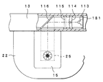
上記フレーム部13の内部における上記透明光学部材15の上部となる位置に、上記LED113,集光レンズ114,LCD115,HOE116が図13に示すように順に配置されている。これらの各部材は、フレーム部13内に設けられた保持枠により挟み込まれるようにして固定されている。このとき、上記LED113は、電気回路基板181に実装された状態で、上記保持枠により固定されるようになっている。また、これらの内のHOE116は、上述したように、LED113からの光を鉛直下方へ向けて反射するように、傾けて配置されている。
The
上記透明光学部材15は、図14に示すように、透明なガラスやプラスチック等により所定の厚みを有するように形成された導光部材182,183と、これらの導光部材182,183の間に挟み込まれながら後方へ向けて光を反射するように傾けて配設された上記HOE25と、を有して構成されている。このような構成において、上記HOE116から反射された光は、HOE25の上側に配置された導光部材182の内部を透過して、該HOE25に到達するようになっている。なお、この導光部材182の内部における光の伝播は、図14に示すように透過のみであっても良いが、透過と内面における全反射とを組み合わせたものであっても構わない。透過と全反射とを組み合わせるような光学設計を行った場合には、透明光学部材15を肉薄にすることが可能となるために、頭部装着部2の軽量化をより一層図ることができる。
As shown in FIG. 14, the transparent
なお、シースルー画像表示光学系は、上述したような各部材の内の、LED113と、集光レンズ114と、LCD115と、HOE116と、HOE25と、導光部材182,183と、を含むものとなっている。
The see-through image display optical system includes the
次に、図15から図19を参照して、被写体と虚像とを同時に眼のピントを合わせて観察し得るようにする構成について説明する。 Next, with reference to FIG. 15 to FIG. 19, a description will be given of a configuration in which a subject and a virtual image can be observed while simultaneously focusing on the eyes.
眼から撮影画枠の虚像までの距離と、眼から被写体までの距離と、の差が大きいと、これらの両方に同時に眼のピントを合わせることができないために、撮影画枠と被写体とを同時に鮮明に観察することができない。 If there is a large difference between the distance from the eye to the virtual image of the shooting image frame and the distance from the eye to the subject, the eye cannot be focused on both of them at the same time. It cannot be observed clearly.
そこで、眼から撮影画枠の虚像までの距離が、眼から被写体までの距離に一致するように設定して、撮影画枠と被写体とを同時に鮮明に観察することができるようにする構成について説明する。 Therefore, a configuration is described in which the distance from the eye to the virtual image of the photographic image frame is set to match the distance from the eye to the subject so that the photographic image frame and the subject can be observed clearly simultaneously. To do.
まず、図15は眼から虚像までの位置を変更する原理を説明するための図である。なお、この図15においては、他の部材等に煩わされることなく原理のみを簡潔に説明するために、上記HOE116等の図示や該HOE116等に係る説明などを省略している。
First, FIG. 15 is a diagram for explaining the principle of changing the position from the eye to the virtual image. In FIG. 15, illustration of the
HOE25の焦点距離をf、LCD115に表示された撮影画枠201の位置からHOE25までの距離をLl、HOE25から虚像VIまでの距離をLi、撮影者が撮影画枠201の対角線の虚像を見込む角度(視角)を2δ、LCD115に表示される撮影画枠の対角線の長さをXlとすると、次の数式1および数式2に示すような関係が成り立つ。
[数1]

[Equation 1]
これらの数式に現れる各変数や定数の内、fはHOE25を設計するときに定まるものであるが、δは撮影者が所望に設定するものであり、虚像までの距離Liが被写体までの距離に一致するようにしたい距離(すなわち、例えば測距により求められる被写体距離)である。従って、これらの値を数式1へ代入することにより、被写体距離と同じ距離の位置に虚像を表示させるためのLCD115の表示位置Llが求まり、さらに、上記各値を数式2へ代入することにより、撮影画枠の視角を撮影画角と一致させるための、LCD115に表示する撮影画枠の大きさXlが求まることになる。
Of the variables and constants appearing in these equations, f is determined when the
図16は、LCD115を虚像距離調整手段たるアクチュエータ252により光軸方向に駆動する構成例を示す図である。この例では、アクチュエータ252として、例えば、電磁モータ、超音波モータ(USM)、静電アクチュエータなど公知のアクチュエータを用いて、上記Llを変更するようにしている。すなわち、LCD115は集光レンズ114の光軸方向に移動可能となるように設けられており、該LCD115を支持する枠部材等に該LCD115を光軸方向に変位させるための虚像距離調整手段たる例えばラック251などが設けられている。このラック251には、アクチュエータ252の回転軸に固定されたピニオンギヤ252a等が噛合して駆動力が伝達されるようになっている。これによって、該アクチュエータ252を所望の量だけ回転させることにより、LCD115を所望の量だけ光軸方向に移動させることができるようになっている。このような構成により、虚像VIまでの距離Liが被写体までの距離に一致するように、上記Llを変更することになる。また、この構成を用いてLlを変更したときには、上記数式2に示すようなXlになるように、視角調整手段たるLCDドライバ117により該LCD115に表示する撮影画枠の大きさを変更することも勿論である。
FIG. 16 is a diagram illustrating a configuration example in which the
なお、上記図16、または次に説明する図17に示す例では、虚像位置を変更すると倍率(被写体を見込む角度2δ)が変化するために、視角調整手段たるLCDドライバ117を用いてLCD115に表示する像の大きさを補正することにより、上記倍率が一定になるように補正を行う。具体的には、LCD115に表示された撮影画枠201の位置からHOE25までの距離Llと、LCD115に表示される撮影画枠201の対角線の長さXlと、の比が一定になるように、LCD115に表示する像の大きさを補正することになる。
In the example shown in FIG. 16 or FIG. 17 described next, since the magnification (angle 2δ at which the subject is viewed) changes when the virtual image position is changed, the display is performed on the
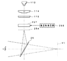
次に、図17は、LCD115の像を一次結像させるようにし、この一次結像の位置を光軸方向に変化させるようにした構成の一例を示す図である。この例では、LCD115を通過した光束の光路上に結像光学系たる結像レンズ253が配設されており、この結像レンズ253によって、該結像レンズ253とHOE25との間の光路上の位置254において、該LCD115の像が一次結像されるようになっている。上記結像レンズ253は、光軸方向に移動可能となるように設けられており、該結像レンズ253を支持する鏡枠等の部材に該結像レンズ253を光軸方向に変位させるための虚像距離調整手段たる例えばラック255などが設けられている。このラック255には、上述と同様に、虚像距離調整手段たるアクチュエータ256の回転軸に固定されたピニオンギヤ256a等が噛合して駆動力が伝達されるようになっている。これによって、該アクチュエータ256を所望の量だけ回転させることにより、結像レンズ253を光軸方向に移動させて、一次結像面の位置254を所望の量だけ光軸方向に移動させることができる。このような構成を用いて、虚像VIまでの距離Liが被写体までの距離に一致するように、上記Llを変更することになる。なお、上記図15で説明した原理におけるLlは、この図17に示す例では、一次結像面の位置254からHOE25までの距離を指すことになる。また、このときにも、LCD115に表示する撮影画枠の大きさを変更するのはいうまでもない。
Next, FIG. 17 is a diagram illustrating an example of a configuration in which an image on the
なお、ここでは、被写体距離に追従して眼から撮影画枠の虚像VIまでの距離を調整するようにしているが、この場合には、撮影者の視線が変化する毎に被写体距離が変化し、撮影画枠の位置を時々刻々と変更することになるために、撮影画枠を高い精度で連続的に調整しないと、視覚的に違和感を生じてしまう可能性がある。また、撮影画枠の位置を時々刻々と調整すると電力消費も大きくなる。そこで、撮影画枠の位置を至近から無限大の距離で数段階(例えば3段階)に分けて調整するようにしてもよい。 Here, the distance from the eye to the virtual image VI of the photographic image frame is adjusted following the subject distance, but in this case, the subject distance changes every time the photographer's line of sight changes. Since the position of the photographic image frame is changed every moment, unless the photographic image frame is continuously adjusted with high accuracy, there is a possibility that a visually uncomfortable feeling may occur. Further, if the position of the photographic image frame is adjusted every moment, the power consumption increases. Therefore, the position of the photographic image frame may be adjusted in several steps (for example, three steps) at an infinite distance from the closest distance.
上記図16や図17に示したような構成例は、LCD115や結像レンズ253をアクチュエータにより機械的に移動させるものであったために、構成がやや複雑であるとともに、アクチュエータ等を配置するスペースが必要になったり、重量が増したりする。さらに、アクチュエータを用いているために、駆動時に雑音が少し発生する可能性があり、このときに発生する雑音が撮影者に不快感を与えることもあり得る。こうした点は、頭部に装着して用いるカメラにおいてはできるだけ解消することが望ましい。次に、図18を参照して説明する構成例は、このような点に鑑みてなされたものである。
In the configuration examples shown in FIGS. 16 and 17, the
図18は、LCDの像を一次結像させるようにし、この一次結像の位置を光軸方向に変化させるようにした構成の他の例を示す図、図19は、上記図18における液体レンズの詳細な構成を示す図である。 FIG. 18 is a diagram showing another example of a configuration in which an image on an LCD is primarily formed and the position of the primary image is changed in the optical axis direction, and FIG. 19 is a liquid lens in FIG. It is a figure which shows the detailed structure of these.
これら図18および図19に示す構成例は、上記図17に示した結像レンズ253に代えて、液体レンズ(FluidFocusレンズ)257を用いるようにしたものである。以下に説明する液体レンズ257は、2004年3月3日にロイヤルフィリップスエレクトロニクス社により発表されたものを用いる例となっている。
18 and 19 uses a liquid lens (Fluid Focus lens) 257 instead of the
まず、図19を参照して、液体レンズ257の構成について説明する。
First, the configuration of the
液体レンズ257は、図19(A),図19(B)に示すように、透明な伝導性液体(Conducting Fluid)265と、この伝導性液体265とは異なる屈折率(異なる光学特性)をもち該伝導性液体265とは混じり合わない(不混和性の)非伝導液体(Insulating Fluid)266とを、透明な短い円筒状部材の内部に封止して構成されている。上記伝導性液体265は例えば水性の液体であり、上記非伝導液体266は例えば油性の液体となっている。そして、これら伝導性液体265と非伝導液体266との境界面が、レンズ面を構成するようになっている。
As shown in FIGS. 19A and 19B, the
上記円筒状部材は、ガラス等で構成された円筒261aと、この円筒261aの底面側を封止するガラス等で構成された円板261bと、該円筒261aの上面側を封止するガラス等で構成された円板261cと、を有して構成されている。
The cylindrical member includes a cylinder 261a made of glass or the like, a disk 261b made of glass or the like that seals the bottom surface side of the cylinder 261a, and glass or the like that seals the upper surface side of the cylinder 261a. And a configured
上記円板261bの上面側外周部から周面にかけて、断面略L字状の電極262bが設けられるとともに、上記円筒261aの内周面、外周面、および上面にかけて、断面略コの字状の電極262aが設けられており、これらは互いに非接触となるように配設されている。
An
上記円筒261aおよび電極262aの内周側には、円筒状の絶縁体263が配設されていて、この絶縁体263の下端側が電極262bに接触して、電極262aと電極262bとが絶縁されるようになっている。
A
この絶縁体263の内周側から上記円板261cの下面側にかけて、疎水性(撥水性)コーティング(Hydrophobic coating)264が設けられている。
A hydrophobic (water repellent)
そして、この疎水性コーティング264の内部に、上記伝導性液体265および非伝導液体266が封止されている。なお、上記電極262bは、伝導性液体265に電気的に接続されるように、疎水性コーティング264よりも内周側に延出されている。
The
このような構成において、上記電極262a,262bに特に電圧を印加しないときには、伝導性液体265が疎水性コーティング264により退けられて、図19(A)に示すように、底面側に集まる略半球状をなし、それ以外の、疎水性コーティング264に接触する部分に非伝導液体266が配分される。
In such a configuration, when no voltage is particularly applied to the
一方、上記電極262aがマイナス、電極262bがプラスとなるように電圧Vを印加すると、図19(B)に示すように、プラスの電荷が上記電極262bから伝導性液体265に伝達される。そして、電極262aの表面にマイナスの電荷が分布するとともに、上記絶縁体263および疎水性コーティング264を介して該電極262aに対向する伝導性液体265の表面にプラスの電荷が分布する。このような電気的誘導によって、伝導性液体265の表面張力(より正確には、伝導性液体265が疎水性コーティング264と接触する界面の張力)が変化する。表面張力が変化すると、伝導性液体265は、疎水性コーティング264の内周面をぬらし始める。このような、電場による疎水性コーティング264の疎水性が弱まるプロセスを、「電子ウェッティング(electrowetting)」という。
On the other hand, when the voltage V is applied so that the electrode 262a is negative and the
こうして、電圧Vを印加することにより、伝導性液体265と非伝導液体266との間のレンズ面の曲率半径が変化するために、レンズの焦点距離が変化する。
Thus, by applying the voltage V, the radius of curvature of the lens surface between the
このような焦点距離の変化は、電極262aと電極262bとの間に印加する電圧を調整することにより、制御することができる。例えば、印加する電圧Vをより高くしてやることにより、分布する電荷量が増えて、図19(A)に示すように凸状(略半球状)をなす伝導性液体265の表面が、完全に平らになったり(レンズ効果なし)、あるいは、図19(B)に示すような凹状になったりする。この図19(B)に示す例では、接触角φが90度よりも小さくなっている。このようにして、収束レンズから発散レンズへスムーズに移行し、またスムーズに元に戻るレンズを実現することができる。
Such a change in focal length can be controlled by adjusting a voltage applied between the electrode 262a and the
図18は、上記図19に示したような液体レンズを用いて、LCD115の像の一次結像の位置を変化させるようにした構成例を示している。
FIG. 18 shows a configuration example in which the primary imaging position of the image of the
すなわち、LCD115とHOE25との間の光路上には、結像光学系であり虚像距離調整手段たる液体レンズ257が配設されていて、この液体レンズ257によるLCD115の像の一次結像面の位置254は、該液体レンズ257に印加する電圧Vを変化させることにより、変更することができるようになっている。
That is, on the optical path between the
すなわち、該液体レンズ257に印加される電圧Vは、虚像距離調整手段たる電圧制御回路258により制御されるように構成されている。
That is, the voltage V applied to the
この電圧制御回路258は、例えば上記第4CPU111に接続されていて、撮影画枠の虚像VIまでの距離Liが、被写体までの距離に一致されるように制御される。
The
なお、このときにも、液体レンズ257の焦点距離を変化させると虚像VIの倍率が変化するために、該液体レンズ257の焦点距離に応じて、LCD115に表示する撮影画枠の大きさを変更することはいうまでもない。
At this time, since the magnification of the virtual image VI changes when the focal length of the
このような、液体レンズ257の焦点距離を変化させて虚像VIまでの距離Liを被写体までの距離に一致させる構成を採用することにより、構成が簡単になって装置をより一層小型軽量化することができる。さらに、アクチュエータが用いられていないために、騒音が発生することはなく、撮影者に不快感を与えることもない。従って、このような構成は、頭部に装着して用いるタイプの頭部装着型カメラや頭部装着型表示装置などの画像システムに、特に有効となる。
By adopting such a configuration in which the focal length of the
なお、上記図18では、虚像VIとして撮影画枠が表示されるときに、該虚像VIの位置を調整する例を示したが、これに限らず、虚像として画像や文字等が表示される場合にも(すなわち、画像や文字を虚像として表示するような表示装置においても)、同様に適用可能であるのはもちろんである。 Note that FIG. 18 shows an example in which the position of the virtual image VI is adjusted when the captured image frame is displayed as the virtual image VI. However, the present invention is not limited to this, and an image, a character, or the like is displayed as a virtual image. Of course, the present invention can be applied in the same manner (that is, even in a display device that displays an image or a character as a virtual image).
次に、図20、図21を参照して、視線方向/角速度検出部7における視線方向検出部の光学系の構成の一例について説明する。図20は視線方向検出部の光学系の一構成例を示す一部断面を含む正面図、図21は視線方向検出部の光学系の一構成例を示す左側面図である。
Next, an example of the configuration of the optical system of the line-of-sight direction detection unit in the line-of-sight direction / angular
上記フレーム部13の内部における上記透明光学部材14の上部となる位置に、上記
LED125,集光レンズ126,反射ミラー127,反射ミラー131,結像レンズ132,バンドパスフィルタ133,CCD134が、図20に示すように、順に配置されている。
The
上記反射ミラー127の下方となる透明光学部材14内には、ハーフミラー128とHOE24とが配設されている。さらに、該ハーフミラー128の側方となる透明光学部材14内には、HOE129が配設されている。
A
このような構成において、上記LED125から赤外光が発光されると、集光レンズ126により平行光束に変換された後に、反射ミラー127により鉛直下方へ反射される。
In such a configuration, when infrared light is emitted from the
この反射ミラー127により反射された赤外光は、透明光学部材14の内部に入って、該透明光学部材14内に配置されているハーフミラー128を透過し、HOE24により観察者の眼へ向けて反射される。
The infrared light reflected by the reflecting
一方、観察者の眼から反射された赤外光は、上記HOE24により上方へ向けて反射され、さらに、ハーフミラー128により側方へ向けて反射される。この反射光は、さらにHOE129により上方へ向けて反射され、フレーム部13内に配設された反射ミラー131に到達する。
On the other hand, the infrared light reflected from the observer's eyes is reflected upward by the
この反射ミラー131により側方へ向けて反射された光は、結像レンズ132とバンドパスフィルタ133とを介して、上記HOE24により反射された赤外光の波長域に係る観察者の眼の像として、CCD134上に結像される。
The light reflected to the side by the reflecting
このCCD134によって変換された画像信号は、上記CDS/AGC回路136、A/D変換回路137、通信制御部173、送受信部172等を介して、上記画像記録/編集装置4へ転送され、該画像記録/編集装置4内の第1CPU161において、後述するように、プルキンエ像の位置と、瞳孔の中心位置と、が求められ、さらにこれらの相対的な関係から視線方向が求められる。
The image signal converted by the
なお、上記ハーフミラー128およびHOE129は、このように例えば透明光学部材14内に配置されるが、このときの位置としては、この頭部装着部2を装着して被写体を観察する観察者の視界に通常入り難いような上部であることが望ましい。
The
これら図20、図21に示したような構成によれば、高い波長選択性と、選択された波長域の光に対する高い反射率と、を有するHOE24を用いるとともに、同様の波長選択性を有するバンドパスフィルタ133をCCD134の前に配置しているために、高いS/N比の信号を得ることが可能になる。
According to the configuration shown in FIGS. 20 and 21, the
そして、このような構成により、被写体を観察している観察者の視線方向を、正確に求めることが可能となる。 With such a configuration, it is possible to accurately determine the line-of-sight direction of the observer who is observing the subject.
続いて、図22、図23を参照して、視線方向/角速度検出部7における視線方向検出部の光学系の構成の他の例について説明する。図22は視線方向検出部の光学系の他の構成例を示す一部断面を含む正面図、図23は視線方向検出部の光学系の他の構成例を示す左側面図である。
Next, another example of the configuration of the optical system of the line-of-sight direction detection unit in the line-of-sight direction / angular
上記図20、図21に示したような構成は、ハーフミラー128およびHOE129が外光に直接さらされることになるために、外光ノイズがCCD134に到達するのを完全に遮断するのは困難である。これに対して、この図22、図23に示すような構成は、観察者の眼へ赤外光を投光する光路と、観察者の眼により反射された赤外光をCCD134により受光する光路と、を完全に分離するようにしたものとなっている。
20 and 21, the
すなわち、この視線方向検出部の光学系においては、上記ハーフミラー128およびHOE129が省略されると共に、HOE24が、上記図20に示したものよりも左右方向にやや長くなるように構成されている。
That is, in the optical system of the line-of-sight direction detection unit, the
そして、上記反射ミラー127により反射された赤外光は、このHOE24の例えば左側部分へ向けて、斜めに入射されるようになっている。HOE24は、この反射ミラー127からの赤外光を、観察者の眼へ向けて、水平方向に少し斜めとなるように投射する。
The infrared light reflected by the
一方、観察者の眼からの反射光は、該HOE24の例えば右側部分により受光されて、上記反射ミラー131へ向けてほぼ鉛直真上に反射される。この反射ミラー131以降の構成等は、上記図20、図21に示したものと同様である。
On the other hand, the reflected light from the observer's eyes is received by, for example, the right side portion of the
これら図22、図23に示したような構成によれば、高い波長選択性と、選択された波長域の光に対する高い反射率と、を有するHOE24を用いるとともに、同様の波長選択性を有するバンドパスフィルタ133をCCD134の前に配置しているために、高いS/N比の信号を得ることが可能になる。そして、外光が照射される透明光学部材14に配置されるのをHOE24のみとしたために、透明光学部材14にハーフミラー128やHOE129が配置されている上記図20、図21の構成に比して、さらに外光ノイズの影響を低減することが可能となる。
According to the configurations shown in FIGS. 22 and 23, the
なお、透明光学部材14内部における光の伝播は、図21や図23に示したように透過のみであっても良いが、上記透明光学部材15内部における光の伝播と同様に、透過と内面における全反射とを組み合わせたものであっても構わない。この透過と全反射とを組み合わせる光学設計を行う場合には、透明光学部材14を肉薄にすることが可能となって、頭部装着部2の軽量化をより一層図ることができる。
The propagation of light inside the transparent
次に、撮像部30を、フレーム部13の側面に対して、ピッチ方向およびヨー方向に相対的に角度調整可能となるように取り付ける構成について、図24および図25を参照して説明する。図24は撮像部30をフレーム部13に取り付ける構成を示す平面図および右側面図、図25は撮像部30を取り付けるためにフレーム部13に設けられた孔の構成を示す右側面図である。
Next, a configuration in which the
本実施例の画像システム1は、撮影者が撮影範囲を示す撮影画枠を指定し、指定された撮影画枠の視角に対応する画角で撮影を行うものであるために、パララックスを補正する必要がある。このパララックスの発生原因として、撮影者の視軸と撮影光軸との水平方向の位置的なずれと、視軸と撮影光軸との角度のずれと、があるが、後者の角度のずれの影響が非常に大きいために、この角度のずれを精密に補正することができるような調整機構(調整手段)を設けたものとなっている。
The
フレーム部13とテンプル部12とは、図24(A)に示すように、丁番78を介して、折り畳み可能に接続されている。この丁番78は、上記フレーム部13から延設されるやや長めの継手29を介して、右眼側の丁番79よりもややフロント部11側から離れた位置に配設されている。
As shown in FIG. 24A, the
上記継手29の側面には、該側面に沿った形状部33aと、該側面から略垂直に立設される形状部33bと、を備えた、正面から見たときに略L字形状をなす調整機構(調整手段)たる台座33が接続されるようになっている。この調整機構は、頭部装着型カメラの調整方法が適用される頭部装着型カメラの調整装置における、フロント部11と撮像部30との相対的な角度を調整するための機構であり、該調整機構を用いることにより、撮像部30に含まれる撮影光学系31の光軸と視軸とを調整することが可能となっている。
The side face of the joint 29 is provided with a shape portion 33a along the side surface and a shape portion 33b erected substantially perpendicularly from the side surface, and an adjustment that is substantially L-shaped when viewed from the front. A
すなわち、上記継手29には、図25に示すように、前方側にピッチ方向調整手段たる孔191が、後方側に該孔191を中心とした円弧状をなすピッチ方向調整手段たる長孔192が、それぞれ穿設されている。これらの孔191,192を介して、ピッチ方向調整手段たるビス34,35をそれぞれ台座33の上記形状部33aに螺合することにより、該台座33が継手29に対して取り付けられている。
That is, as shown in FIG. 25, the joint 29 has a
また、上記台座33の形状部33bには、図24(A)に示すように、前方側にヨー方向調整手段たる孔193が、後方側に該孔193を中心とした円弧状をなすヨー方向調整手段たる長孔194が、それぞれ穿設されている。これらの孔193,194を介して、図24(B)に示すように、ヨー方向調整手段たるビス36,37をそれぞれ撮像部30の底面側に螺合することにより、該撮像部30が台座33に対して取り付けられている。なお、上記撮像部30の背面側からはケーブル38が延出されていて、被写体側に曲折された後に、上記フレーム部13内の電気回路等に接続されている。
Further, in the shape portion 33b of the
このような構成において、ビス34およびビス35をやや緩めた状態で、ビス35が挿通される長孔192内の位置を変更することにより、台座33がビス34を中心として回動し、台座33、ひいてはこの台座33に取り付けられている撮像部30のピッチ方向の角度調整を行うことができる。こうして、所望の位置に調整された後には、上記ビス34およびビス35を固締めすれば良い。
In such a configuration, by changing the position in the
同様に、ビス36およびビス37をやや緩めた状態で、ビス37が挿通される長孔194内の位置を変更することにより、撮像部30がビス36を中心として台座33に対して回動し、該撮像部30のヨー方向の角度調整を行うことができる。こうして、所望の位置に調整された後には、同様に、上記ビス36およびビス37を固締めすることになる。
Similarly, by changing the position in the
このような構成によれば、シースルー画像表示部6と撮像部30との相対的なピッチ方向およびヨー方向の角度調整を行うことが可能となる。さらに、撮像部30が台座を介してフロント部11に固定されているために、テンプル部12を折り畳んでも撮像部30が折り畳まれることはなく、撮像部30とシースルー画像表示部6との相対的な角度ずれが発生する可能性が小さくなる。また、調整機構が簡単であるために、安価に構成することが可能となる。
According to such a configuration, it is possible to adjust the relative angle between the see-through
なお、上述においては、撮像部30と台座33との相対的なヨー方向の角度を調整し、フレーム部13の側面の継手29と台座33との相対的なピッチ方向の角度を調整するようにしたが、これとは逆に、台座33に対する撮像部30の取り付け位置を変更することにより、撮像部30と台座33との相対的なピッチ方向の角度を調整し、台座33に対するフレーム部13の取り付け位置を変更することにより、フレーム部13の側面の継手29と台座33との相対的なヨー方向の角度を調整するように構成することも可能である。
In the above description, the relative angle in the yaw direction between the
続いて、図26から図36を参照して、シースルー画像表示部6による画像の表示例について説明する。
Next, an example of displaying an image by the see-through
まず、図26は、シースルー表示における初期状態の表示例を示す図である。カメラ1の電源を投入するか、またはシステムをリセットしたときに、この図26に示すような表示が行われるようになっている。このときには、図示のように、標準レンズ(例えば、画角が50度であるものとする)に相当する撮影範囲を示す撮影画枠201がシースルー表示される(つまり、撮影者から見たときの視角が50度となるような撮影画枠201がシースルー表示される)ようになっている。
First, FIG. 26 is a diagram illustrating a display example of an initial state in the see-through display. When the
次に、図27は、テレへのズームが行われたときの表示例を示す図である。表示される撮影画枠201が、上記図26に示したよりもテレに対応する撮影範囲を示すものになっている。この撮影画枠201の変更は、上述したように、例えば上記ズームスイッチ75の操作により行われ、このときには撮像部30の撮影画角も該撮影画枠201の視角に一致するように、上記撮影光学系31の焦点距離が変更される。具体的には、上記図26に示したような標準レンズの焦点距離に対応する撮影範囲において、該ズームスイッチ75のテレスイッチ75aを操作することにより、この図27に示すような望遠側への変更が行われる。
Next, FIG. 27 is a diagram illustrating a display example when zooming to tele is performed. The displayed
続いて、図28は、ワイドへのズームおよび露出補正が行われたときの表示例を示す図である。表示される撮影画枠201が、上記図26に示したよりもワイドに対応する撮影範囲を示すものになっているとともに、この撮影画枠201の例えば右下に、露出補正量が情報表示202として表示されている。この図に示す例では、例えば上記露出補正スイッチ76により、+1.0の露出補正が行われたことが示されている。なお、露出補正は、数字で示すに限るものではなく、棒グラフや指標などの各種の表示を用いても構わないことは勿論である。また、この図28に示すような撮影画枠201は、例えば上記図26に示したような標準レンズの焦点距離に対応する撮影範囲において、上記ズームスイッチ75のワイドスイッチ75bを操作することにより、設定される。
Next, FIG. 28 is a diagram illustrating a display example when zoom to wide and exposure correction are performed. The displayed
また、図29は、電子ビュー表示を行うときの表示例を示す図である。例えば上記F/Vスイッチ72によりビューモード(V)が選択されると、この図に示すように、撮像部30で撮像された電子画像203が虚像として撮影者の目に投影されるようになっている。なお、この電子ビューとして表示する画像の大きさは、該画像の解像度により設定することができ、例えば解像度が低い場合は画像を小さく表示すれば良い。
FIG. 29 is a diagram illustrating a display example when electronic view display is performed. For example, when the view mode (V) is selected by the F /
図30は、動画を録画中の表示例を示す図である。例えば上記録画スイッチ74が操作されて録画中となったときには、この図30に示すように、撮影範囲を示す撮影画枠201が表示されるとともに、録画中であることを示す情報表示204が「REC」の文字として、撮影画枠201の例えば右下に表示されるようになっている。この録画中であることを示す表示も、上述と同様に、文字に限るものではない。
FIG. 30 is a diagram illustrating a display example during video recording. For example, when the
図31は、マニュアルモード時の表示例を示す図である。例えば上記FA/A/Mスイッチ71が操作されることによりマニュアルモード(M)に設定されているときには、該マニュアルモード(M)を示す情報表示205が「MANU」の文字として、撮影画枠201の例えば右下に表示されるようになっている。一方、「MANU」の情報表示205が行われていないときには、オートモード(A)であることになる。
FIG. 31 is a diagram illustrating a display example in the manual mode. For example, when the manual mode (M) is set by operating the FA / A /
図32は、フルオートモードで動画を録画中の表示例を示す図である。例えば上記FA/A/Mスイッチ71が操作されることによりフルオートモード(FA)に設定されていて、かつ録画スイッチ74が操作されて録画中となったときには、この図32に示すように、撮影範囲を示す撮影画枠201が表示されるとともに、フルオートモードであることを示す情報表示206が「FA」の文字として、また、録画中であることを示す情報表示207が「REC」の文字として、撮影画枠201の例えば右下に表示されるようになっている。これらのフルオードモードであることや録画中であることを示す表示も、上述と同様に、文字に限るものではない。
FIG. 32 is a diagram illustrating a display example during video recording in the full auto mode. For example, when the full auto mode (FA) is set by operating the FA / A /
図33は、撮影光学系31の焦点距離fが焦点調節可能な下限値k1に達しているにもかかわらず、さらに小さい方へ操作されようとしている場合にシースルー表示される警告表示208の例を示す図である。すなわち、ワイド側へのズーム操作を行ってズームのワイド端に達したときに、依然としてワイド側へのズーム操作が行われている場合に、この警告表示208が撮影範囲を示す撮影画枠201の表示とともに行われる。
FIG. 33 shows an example of a
図34は、撮影光学系31の焦点距離fが焦点調節可能な上限値k2に達しているにもかかわらず、さらに大きい方へ操作されようとしている場合にシースルー表示される警告表示209の例を示す図である。すなわち、テレ側へのズーム操作を行ってズームのテレ端に達したときに、依然としてテレ側へのズーム操作が行われている場合に、この警告表示209が撮影範囲を示す撮影画枠201の表示とともに行われる。
FIG. 34 shows an example of a
図35は、静止画を撮影する操作が行われたときの表示例を示す図である。このときには、撮影範囲を示す撮影画枠201が表示されるとともに、静止画を記録したことを示す情報表示210が「REL」の文字として、撮影画枠201の例えば右下に表示されるようになっている。この静止画を記録したことを示す表示も、上述と同様に、文字に限るものではない。
FIG. 35 is a diagram illustrating a display example when an operation for capturing a still image is performed. At this time, the
図36は、キャリブレーションモードにおける表示例を示す図である。例えば、上記第1操作スイッチ162のメニューボタン63やメニュー選択スイッチ66,67,68,69、確定スイッチ65などを操作することによりキャリブレーションモードが選択されると、この図36に示すような表示を行うようになっている。すなわち、ここでは、キャリブレーションモードであることを示す情報表示211が、「CAL」の文字として、視野の例えば右下に表示されるとともに、さらに、キャリブレーション用の指標P1〜P5が、後述するように、順次点滅して表示されるようになっている。これらの内の、指標P1は視野の中央部に、指標P2は視野の上部に、指標P3は視野の右側部に、指標P4は視野の下部に、指標P5は視野の左側部に、それぞれ表示される。
FIG. 36 is a diagram illustrating a display example in the calibration mode. For example, when the calibration mode is selected by operating the
なお、上述したような各表示において、通常の情報表示は上記LED113の中の例えばG(緑)のダイオードを発光させることにより行い、警告表示は上記LED113の中の例えばR(赤)のダイオードを発光させることにより行うようにすると良い。
In each display as described above, normal information display is performed by causing, for example, a G (green) diode in the
次に、図37〜図39を参照して、上述したような被写体までの距離に基づくパララックスの補正の原理について説明する。図37は被写体と撮影光学系とCCDとの光学的な関係を説明するための図、図38はHOEとこのHOEにより形成される虚像と眼との光学的な関係を説明するための図、図39はパララックスを補正するのに必要な虚像のシフト量を説明するための図である。 Next, the principle of parallax correction based on the distance to the subject as described above will be described with reference to FIGS. FIG. 37 is a diagram for explaining the optical relationship between the subject, the photographing optical system, and the CCD, and FIG. 38 is a diagram for explaining the optical relationship between the HOE, the virtual image formed by the HOE, and the eye. FIG. 39 is a diagram for explaining the shift amount of the virtual image necessary for correcting the parallax.
図37に示すように、CCD87の撮像領域の水平方向のサイズをh2、撮影光学系31の焦点距離をf、撮影光学系31の主点からCCD87までの距離をf+x、撮影光学系31の主点から被写体Oまでの距離をL2、CCD87で撮影される被写体Oの水平方向の長さをH2、水平方向の撮影画角をθ2、とすると、次の数式3に示すような関係式が成り立つ。
[数3]
[Equation 3]
一方、図38に示すように、撮影者の瞳Pの位置から撮影範囲を示す水平方向の撮影画枠の位置(虚像VI)までの距離をL1、該撮影画枠の水平方向の長さをH1、瞳Pの位置から水平方向の長さH1でなる該撮影画枠を見込む角度(視角)をθ1とすると、次の数式4に示すような関係式が成り立つ。
[数4]
[Equation 4]
撮影者が設定した撮影範囲で撮影するためには、撮影画角と視角が等しくなること、すなわち、θ2=θ1であることが必要である。このθ2=θ1が成り立つ条件の下では、数式3の右辺と数式4の右辺とが等しくなるために、撮影光学系31の焦点距離fは、次の数式5に示すように求められる。
[数5]
[Equation 5]
一方、レンズの結像原理から、次の数式6が成り立つ。
[数6]
[Equation 6]
これら数式5と数式6とから、xを消去することにより、次の数式7が導かれる。
[数7]
[Equation 7]
この数式7から、被写体距離L2を求めることができれば焦点距離fを求めることができることがわかる。
From
ここで、通常の被写体においてはh2/L2≪H1/L1の関係が成立するために、計算を簡略化したいときや、被写体距離を求める手段を備えていないときは、次の数式8により近似値を求めることができる。
[数8]
[Equation 8]
次に、パララックスの補正原理について、図39を参照して説明する。 Next, the parallax correction principle will be described with reference to FIG.
まず、パララックスの補正の原理を説明する際の前提条件として、撮影光学系31の光軸方向と撮影者の視軸の方向とは、ともに顔面に対して垂直であるものとし、これらの光軸と視軸とは距離Xだけ隔てて配置されているものとする。ここに、パララックスは、光軸と視軸とが距離Xだけ離れていることに起因して発生するものである。なお、光軸と視軸とが相対的に傾いている場合には、大きなパララックスを生ずる要因となり得るために、これらは平行となるように調整する必要がある。このために、上記図24、図25に示したような調整機構を用いて、光軸と視軸との調整を行うようになっている。
First, as a precondition for explaining the principle of parallax correction, it is assumed that the optical axis direction of the photographing
図39の実線および点線に示すように、もし、撮影範囲を示す撮影画枠の虚像VI0までの距離と、被写体Oまでの距離と、が同じであれば、撮影者が観察している範囲と撮像部30が撮像している範囲とのずれ量(パララックス)は、Xとなって不変である。しかし、実際には、撮影者の瞳Pから虚像VI1までの距離L1は、撮影光学系の主点から被写体Oまでの距離L2と異なるために、虚像としての撮影画枠が示す範囲を実際の撮像範囲に合致させるためのパララックス補正量X’は、次の数式9に示すようになる。
[数9]
[Equation 9]
撮影画枠の虚像VI1の倍率(つまり、LCD115上に表示される像に対する虚像の大きさの比)の逆数をβとすると、パララックスを補正するために、LCD115上に表示する像のシフト量SPは、次の数式10に示すようになる。
[数10]
[Equation 10]
従って、第4CPU111は、この数式10で表わされる量SPだけ、LCD115に表示する像の位置をシフトさせるように、上記LCDドライバ117を制御することになる。これにより、虚像VI1の位置が距離X’だけシフトされて虚像VI2となり、図39の2点鎖線に示すように、虚像の撮影画枠が示す範囲が、実際の撮像範囲に一致する。
Accordingly, the
このように、パララックス補正を行うためのシフト量SPは、被写体距離L2に依存しているために、被写体距離が異なる毎に、随時行うことが基本となる。 Thus, since the shift amount SP for performing the parallax correction depends on the subject distance L2, it is basically performed whenever the subject distance is different.
しかしながら、例えば、β=1/100、L1=2m、L2=2m、X=4cmの場合を例に取ると、シフト量SPは0.4mmとなるが、このパララックス補正量を次のような数式11、
[数11]
[Equation 11]
なお、以上の説明においては、被写体距離L2を三角測距の原理に基づいて求めるようになっている。すなわち、投光用LED16aの光を被写体へ投光して、該被写体から反射した光を上記CCD87で撮像し、該CCD87上の像の位置から、三角測距の原理に基づいて求めるようになっている。
In the above description, the subject distance L2 is obtained based on the principle of triangulation. That is, the light emitted from the LED for projection 16a is projected onto the subject, the light reflected from the subject is imaged by the
また、L2は視線方向の被写体距離であるために、投光用LED16aを、視線検出を行う眼になるべく近い位置に配置して、公知の投光方向を制御する手段により、視線方向(θ)に投光するようにすれば良い。 Since L2 is the subject distance in the line-of-sight direction, the LED 16a for light projection is arranged as close as possible to the eye for detecting the line-of-sight, and the line-of-sight direction (θ) is controlled by a known means for controlling the light projection direction. You should make it light up.
さらに、上述したような三角測距の原理に基づいて被写体距離を求める代わりに、オートフォーカスを行ったときのフォーカスレンズ85の位置から被写体距離L2を求めるようにしても構わない。すなわち、被写体の位置が無限大であると仮定して、上記図11に示したようなAF処理回路98により、視線方向(θ)と同じ画角の所定範囲にある被写体の画像信号の高周波成分が最大になる位置に、フォーカスレンズ85を駆動し(いわゆるコントラスト方式による焦点検出を行い)、このフォーカスレンズ85の位置から逆に被写体距離L2を求めるようにすれば良い。この場合には、視線方向(θ)の被写体と、上記AF処理の対象となる視線方向(θ)と同じ画角の被写体と、は厳密には一致しないが、被写体はある大きさを有するために実用上の問題が生じることはない。
Furthermore, instead of obtaining the subject distance based on the principle of triangulation as described above, the subject distance L2 may be obtained from the position of the
続いて、図40を参照して、撮像部30と視線方向/角速度検出部7の視線方向検出部とが所定距離だけ隔てて配置されていることに起因して生じるパララックスを考慮する技術について説明する。図40は、視線方向にある被写体を撮像部から見るときの角度の関係を示す図である。
Subsequently, referring to FIG. 40, a technique that takes into account the parallax caused by the
例えば、視線方向/角速度検出部7により検出された視線方向にある被写体に、撮像部30の撮影光学系31のピントを合わせようとする場合を考える。被写体までの距離が遠い場合には、撮像部30から見た撮影者の視線方向にある被写体は、撮影者が実際に注視している被写体にほぼ一致するが、被写体までの距離が近くなると、これらにずれが生じてくる。従って、ずれた位置にある被写体にピントを合わせたとしても、撮影者が注視している被写体にピントが合うとは限らない。図40は、このようなパララックスが生じているときの位置関係の例を示している。
For example, consider a case where the subject of the imaging
今、撮影者が、撮影光学系31の光軸と平行な視軸に対して角度θをなす方向の、距離Lにある被写体Oを注視しているものとする。このときに、撮影光学系31の光軸と撮影者の瞳との間の距離をXe とする。また、撮影光学系31の光軸と、撮影光学系31の主点Hと被写体Oを結ぶ直線と、のなす角度をθ’とする。すると、次の数式12が成り立つ。
[数12]
[Equation 12]
従って、視線方向/角速度検出部7により検出された視線方向θと、AF処理回路98等により検出された被写体距離Lと、設計的に定まるXe と、をこの数式12に代入して上記角度θ’を求め、この求めた角度θ’の方向に該当する被写体に撮影光学系31のピントを合わせるようにすればよい。なお、被写体距離Lが大きい場合には、数式12の右辺の第2項を無視することができるために、θ’≒θとなり、つまりパララックスの影響をほぼ考えなくて良いことが分かる。
Accordingly, the line-of-sight direction θ detected by the line-of-sight direction /
なお、上記被写体距離Lは、上述したように、三角測距により求めたものでも良いし、あるいはコントラスト方式により焦点検出を行った結果に基づいて求めたものであっても構わない。 The subject distance L may be obtained by triangulation as described above, or may be obtained based on the result of focus detection by the contrast method.
次に、以上説明したような画像システムの動作について、図48および図49を参照して説明する。図48は画像システムの動作の一部を示すフローチャート、図49は画像システムの動作の他の一部を示すフローチャートである。これら図48および図49は、画像システムの動作の流れを、図面の都合上、2図に分割して示したものである。 Next, the operation of the image system as described above will be described with reference to FIGS. 48 and 49. FIG. FIG. 48 is a flowchart showing a part of the operation of the image system, and FIG. 49 is a flowchart showing another part of the operation of the image system. FIG. 48 and FIG. 49 show the flow of the operation of the image system divided into two diagrams for convenience of drawing.
この画像システム1の電源を投入するか、またはシステムをリセットすると、標準レンズ(上述したように、例えば、画角が50度となる。)に相当する撮影範囲を示す撮影画枠を、上記シースルー画像表示部6により上記図26に示したようにシースルー表示する(ステップS1)。
When the power of the
次に、上記第2CPU121に内蔵されているタイマ123をチェックすることにより、所定時間が経過したか否かを判断する(ステップS2)。
Next, it is determined whether or not a predetermined time has elapsed by checking a
ここで、所定時間が経過していると判断された場合には、図8に示したような第1操作スイッチ162や、図10に示したような第2操作スイッチ171などの各種スイッチの入力状況をモニタする(ステップS3)。
Here, if it is determined that the predetermined time has elapsed, input of various switches such as the
なお、上記ステップS2におけるタイマは、所定時間が経過して上記ステップS3に移行した時点で、再度、計時を開始するものとなっている。そして、タイマによる計時が所定時間に達していないときには、上記ステップS3におけるスイッチのモニタは行わないようになっている。このように、タイマをチェックしながら所定の時間間隔でスイッチの入力状況を確認することにより、各CPUの負荷を軽減することができるとともに、スイッチのチャタリングによる誤動作を防止することも可能となっている。なお、後述するステップS14,S20,S25のタイマは、上記ステップS2におけるタイマと同様の機能を果たすものとなっている。 The timer in step S2 starts counting again when the predetermined time has passed and the process proceeds to step S3. When the time measured by the timer has not reached the predetermined time, the switch is not monitored in step S3. In this way, by checking the switch input status at predetermined time intervals while checking the timer, it is possible to reduce the load on each CPU and to prevent malfunction due to switch chattering. Yes. Note that the timers in steps S14, S20, and S25, which will be described later, perform the same functions as the timers in step S2.
上記ステップS3の処理が終了したら、次に、後述するような危険防止のサブルーチンを実行する(ステップS4)。 When the process of step S3 is completed, a danger prevention subroutine as described later is executed (step S4).
このステップS4の処理が終了するか、または上記ステップS2において所定時間が経過していないと判断された場合には、画像システム1が、オートモード(A)もしくはマニュアルモード(M)の何れかに設定されているか、または、これらのモード以外(つまりフルオートモード(FA))に設定されているか、を判断する(ステップS5)。このモード設定は、上述したように、FA/A/Mスイッチ71の操作により行われるものである。
When the process of step S4 ends or when it is determined in step S2 that the predetermined time has not elapsed, the
ここで、オートモード(A)でもマニュアルモード(M)でもなく、つまりフルオートモード(FA)であると判断されたときは、録画スイッチ74により録画モードに設定されているか否かを判断する(ステップS6)。 Here, when it is determined that neither the auto mode (A) nor the manual mode (M), that is, the full auto mode (FA) is determined, it is determined whether or not the recording mode is set by the recording switch 74 ( Step S6).
ここで、もし録画モードに設定されていないときには、上記ステップS2へ戻って、上述したような処理を繰り返して行う。 Here, if the recording mode is not set, the process returns to step S2 and the above-described processing is repeated.
また、上記ステップS6において、録画モードに設定されていると判断された場合には、標準撮影画枠に設定するとともに、フルオートモードであることを示す情報表示206(文字「FA」)と、録画中であることを示す情報表示207(文字「REC」)と、を上記図32に示したようにシースルー表示する(ステップS7)。 If it is determined in step S6 that the recording mode is set, the information display 206 (character “FA”) indicating that the recording mode is set and the full auto mode is set, An information display 207 (character “REC”) indicating that recording is in progress is displayed as shown in FIG. 32 (step S7).
そして、動画データ、角速度データ、視線方向データ、音声データを、上記ディスク249等に記録してから(ステップS8)、上記ステップS2へ戻って、上述したような処理を繰り返して行う。
Then, after moving image data, angular velocity data, line-of-sight direction data, and audio data are recorded on the
一方、上記ステップS5において、オートモード(A)またはマニュアルモード(M)の何れかが設定されていると判断された場合には、露出補正が設定されているか否かを判断する(ステップS9)。 On the other hand, if it is determined in step S5 that either the auto mode (A) or the manual mode (M) is set, it is determined whether exposure correction is set (step S9). .
ここで、露出補正が設定されていると判断された場合には、例えば図28に示したように、設定されている露出補正量(補正値)を情報表示202としてシースルー表示する(ステップS10)。 If it is determined that exposure correction is set, for example, as shown in FIG. 28, the set exposure correction amount (correction value) is displayed as a see-through display as the information display 202 (step S10). .
このステップS10の処理が終了するか、または上記ステップS9において露出補正が設定されていないと判断された場合には、画像システム1が、撮像部30で撮像された画像をシースルー表示するビューモード(V)に設定されているか、または、撮影範囲である撮影画枠のみを表示するフレームモード(F)に設定されているかを判断する(ステップS11)。このモード設定は、上述したように、F/Vスイッチ72の操作により行われるものである。
When the process of step S10 ends or when it is determined in step S9 that the exposure correction is not set, the
ここで、モードがフレームモード(F)に設定されていると判断されたときには、次に、画像システム1が、オートモード(A)に設定されているか、または、マニュアルモード(M)に設定されているか、を判断する(ステップS12)。このモード設定は、上述したように、FA/A/Mスイッチ71の操作により行われるものである。
Here, when it is determined that the mode is set to the frame mode (F), the
ここに、オートモード(A)は、撮影光学系31の焦点距離が所定値以上であるときは、フレームモード(F)に設定されていても、撮像部30により撮像された画像を自動的に拡大してシースルー表示するモードとなっている。このような表示を行うことにより、望遠撮影においても面倒な操作を行うことなく被写体の詳細を容易に確認することができるとともに、通常の焦点距離(上記所定値未満の焦点距離)においては撮影範囲を示す撮影画枠が表示されるのみであるために、長時間の撮影においても違和感なく撮影を行うことが可能となる。
Here, in the auto mode (A), when the focal length of the photographing
一方、マニュアルモードは、上述したように、上記シースルー表示を行うか否かをマニュアルで設定するものであり、通常は撮影画枠の表示のみを行うモードである。 On the other hand, as described above, the manual mode is a mode in which whether or not to perform the see-through display is manually set, and is usually a mode in which only the photographing image frame is displayed.
上記ステップS12において、マニュアルモード(M)が選択されていると判断された場合には、上記図31に示したように「MANU」の情報表示205を行う(ステップS13)。
If it is determined in step S12 that the manual mode (M) is selected, the “MANU”
そして、タイマをチェックすることにより、所定時間が経過したか否かを判断する(ステップS14)。 Then, it is determined whether or not a predetermined time has elapsed by checking the timer (step S14).
ここで、所定時間が経過している場合には、上記ステップS4の危険防止の処理において、後述する図50のステップS41で求めた被写体までの距離に基づき、撮影者の観察している範囲と撮像部30による撮影範囲とのずれであるパララックスを補正するために必要な補正値を上述したような原理に基づき算出する(ステップS15)。
Here, when the predetermined time has elapsed, in the risk prevention process in step S4, based on the distance to the subject obtained in step S41 in FIG. A correction value necessary for correcting the parallax, which is a deviation from the imaging range by the
そして、このステップS15で算出された補正値に基づいて、正しい位置に撮影画枠を表示するように、撮影画枠の表示を更新する(ステップS16)。このような処理を行うことにより、被写体距離が変化した場合にも、正確に撮影範囲を表示することができるようになっている。なお、このステップS16においては、HOE25から上記撮影範囲を表わす撮影画枠の虚像までの距離も、上記図15〜図18に示したような手段の何れかにより調整するようになっている。
Based on the correction value calculated in step S15, the display of the photographic image frame is updated so that the photographic image frame is displayed at the correct position (step S16). By performing such processing, the shooting range can be accurately displayed even when the subject distance changes. In step S16, the distance from the
一方、上記ステップS12において、オートモード(A)に設定されていると判断されたときは、次に、撮影光学系31の焦点距離が所定値αよりも大きい望遠側に設定されているか否かを判断する(ステップS17)。
On the other hand, if it is determined in step S12 that the auto mode (A) is set, then whether or not the focal length of the photographing
ここで、撮影光学系31の焦点距離が所定値α以下であると判断された場合には、上記ステップS14の処理に移行する。また、撮影光学系31の焦点距離が所定値αよりも大きいと判断された場合、あるいは上記ステップS11において、ビューモード(V)が設定されていると判断された場合には、撮像部30により撮像した電子画像をシースルー画像表示部6により被写体に重畳してシースルー表示する(ステップS18)。
If it is determined that the focal length of the photographic
このステップS18の処理が終了した場合、上記ステップS16の処理が終了した場合、または上記ステップS14において所定時間が経過していないと判断された場合には、撮影者が上記画像記録/編集装置4のワイドスイッチ75bを操作することにより、撮影画枠の大きさを広く(W)したか否かを判断する(ステップS19)。
When the process of step S18 is completed, when the process of step S16 is completed, or when it is determined that the predetermined time has not elapsed in step S14, the photographer uses the image recording /
ここで、撮影画枠の大きさを広く(W)する操作が行われていると判断された場合には、タイマをチェックすることにより、所定時間が経過しているか否かを判断する(ステップS20)。 Here, when it is determined that an operation for widening (W) the size of the photographic image frame is performed, it is determined whether or not a predetermined time has elapsed by checking a timer (step S20).
そして、所定時間が経過していると判断された場合には、撮影光学系31の焦点距離fが、焦点調節可能な下限値k1に達しているにもかかわらず、さらにこの下限値k1よりも小さい方へ操作されようとしているか否かを判断する(ステップS21)。
If it is determined that the predetermined time has elapsed, the focal length f of the photographing
ここで、焦点調節可能な下限値k1よりも小さい方へ操作されようとしている場合には上記図33に示したように、シースルーにより警告表示208を行う(ステップS22)。また、焦点距離fが焦点調節可能な下限値k1にまだ達していない場合には、撮影光学系31のバリエータレンズ82を駆動することにより焦点距離fを小さくして、撮影者が設定した撮影範囲になるように撮影光学系31の焦点距離を設定する(ステップS23)。
Here, when the operation is to be made to be smaller than the lower limit k1 at which the focus can be adjusted, as shown in FIG. 33, a
一方、上記ステップS19において、撮影画枠の大きさを広く(W)する操作が行われていないと判断された場合には、上記画像記録/編集装置4のテレスイッチ75aを介して、撮影画枠の大きさを狭く(T)する操作が行われているか否かを判断する(ステップS24)。
On the other hand, if it is determined in step S19 that an operation to widen (W) the size of the photographic image frame has not been performed, the photographic image is transmitted via the teleswitch 75a of the image recording /
ここで、撮影画枠の大きさを狭く(T)する操作が行われていると判断された場合には、タイマをチェックすることにより、所定時間が経過しているか否かを判断する(ステップS25)。 Here, if it is determined that an operation for reducing (T) the size of the photographic image frame is performed, it is determined whether or not a predetermined time has elapsed by checking a timer (step S1). S25).
そして、所定時間が経過していると判断された場合には、撮影光学系31の焦点距離fが、焦点調節可能な上限値k2に達しているにもかかわらず、さらにこの上限値k2よりも大きい方へ操作されようとしているか否かを判断する(ステップS26)。
If it is determined that the predetermined time has elapsed, the focal length f of the photographing
ここで、焦点調節可能な上限値k2よりも大きい方へ操作されようとしている場合には上記図34に示したように、シースルーにより警告表示209を行う(ステップS27)。また、焦点距離fが焦点調節可能な上限値k2にまだ達していない場合には、撮影光学系31のバリエータレンズ82を駆動することにより焦点距離fを大きくして、撮影者が設定した撮影範囲になるように撮影光学系31の焦点距離を設定する(ステップS28)。
Here, if it is about to be operated to a value larger than the upper limit k2 at which the focus can be adjusted, as shown in FIG. 34, a
上記ステップS24において撮影画枠の大きさを狭く(T)する操作が行われていないと判断された場合、上記ステップS20あるいはステップS25において所定時間が経過していないと判断された場合、または、上記ステップS22,S23,S27、あるいはステップS28の処理が終了した場合、には、画像記録/編集装置4の第2操作スイッチ171に含まれる録画スイッチ74による動画記録の操作(あるいは、第1操作スイッチ162による動画記録の操作)が行われて録画モードが設定された否かを判断する(ステップS29)。
If it is determined in step S24 that an operation for reducing (T) the size of the photographic image frame has not been performed, if it is determined in step S20 or step S25 that a predetermined time has not elapsed, or When the process of step S22, S23, S27 or step S28 is completed, the moving image recording operation (or the first operation) by the
ここで、録画モードが設定されている場合には、図30に示したように、「REC」の文字による情報表示204をシースルーにより行ってから(ステップS30)、録画を開始する(ステップS31)。
Here, when the recording mode is set, as shown in FIG. 30, the
このステップS31の処理が終了するか、または、上記ステップS29において録画モードが設定されていないと判断された場合には、画像記録/編集装置4の第2操作スイッチ171に含まれるレリーズスイッチ73による静止画撮影の操作(あるいは、第1操作スイッチ162による静止画撮影の操作)が行われたか否かを判断する(ステップS32)。
When the processing of step S31 ends or when it is determined in step S29 that the recording mode is not set, the
ここで、静止画撮影の操作が行われたと判断される場合には、まず、静止画像の記録を行ってから(ステップS33)、図35に示したように、静止画の記録が行われたことを示す「REL」の文字による情報表示210をシースルーにより行う(ステップS34)。
If it is determined that a still image shooting operation has been performed, a still image is first recorded (step S33), and then a still image is recorded as shown in FIG. The
このステップS34が終了するか、または、上記ステップS32においてレリーズスイッチ73による静止画撮影の操作が行われていないと判断される場合には、上記ステップS2の処理に戻って、上述したような動作を繰り返して行う。
If this step S34 is completed or if it is determined in step S32 that the operation of taking a still image by the
図50は、上記図48のステップS4に示した危険防止のサブルーチンの詳細を示すフローチャートである。 FIG. 50 is a flowchart showing details of the danger prevention subroutine shown in step S4 of FIG.
上述したように、スイッチ39を操作することにより、シースルー画像の表示を所望に禁止することができるようにして安全を図るようにしているが、これに代えて、またはこれと共に、撮影者の状態を検出して、検出された状態に応じて撮影動作中のシースルー表示を自動的に禁止するようにしたものである。
As described above, by operating the
この危険防止の処理を開始すると、まず、被写体までの距離を測定する(ステップS41)。このときの測距原理は、次のようになっている。 When this danger prevention process is started, first, the distance to the subject is measured (step S41). The distance measurement principle at this time is as follows.
フレーム部13の中央部に配置された投光用発光部16の投光用LED16aから発光された光束は、集光レンズ16bによりほぼ平行光束となって射出され、被写体に照射される。この光は、該被写体によって反射され、撮影光学系31を介してCCD87の撮像面に入射する。
The light beam emitted from the light projecting LED 16a of the light projecting
このときに、集光レンズ16bと撮影光学系31との間の距離をL、撮影光学系31の主点からCCD87の撮像面までの距離をf1、被写体からの反射光のCCD87の撮像面上における結像位置と撮影光学系31の光軸が該撮像面に交差する位置との距離を△L、とすると、被写体までの距離Rは、公知の三角測距の原理に基づいて、次の数式13により求めることができる。
[数13]
[Equation 13]
このようにして求めた距離Rを、第2CPU121の内部に設けられたRAM122に一時的に記憶する。
The distance R thus obtained is temporarily stored in a
続いて、上記角速度センサ141,142により、独立な2軸周りの角速度を検出して、上記RAM122に一時的に記憶する(ステップS42)。
Subsequently, the
次に、今回取得した測距結果と、以前に取得した測距結果と、を比較して、撮影者の前方にある物体が相対的に近づいているか否かを判断する(ステップS43)。 Next, the distance measurement result acquired this time is compared with the distance measurement result acquired previously, and it is determined whether or not an object in front of the photographer is relatively approaching (step S43).
ここで、前方の物体が近づいていると判断された場合には、さらに、今回取得した被写体までの距離Lが、所定の距離k3よりも近い距離となっているか否かを判断する(ステップS44)。 If it is determined that the object ahead is approaching, it is further determined whether or not the distance L to the subject acquired this time is closer than the predetermined distance k3 (step S44). ).
ここで、上記距離Lが所定の距離k3よりも近いと判断されたときには、所定の警告マークを上記シースルー画像表示部6によりシースルー表示する(ステップS45)。なお、ここでは、前方の物体までの距離のみを考慮して、該前方の物体の移動速度は考慮していないが、上記ステップS43において、前方物体までの距離を求めるとともにさらに移動速度(近接してくるスピード)も求めて、該移動速度に応じて上記所定の距離k3を適応的に設定するようにしても良い。この場合には、前方物体が近接してくるスピードが速いほど、上記所定の距離k3を大きくするように設定する。そして、前方物体の移動速度は、上記距離Lを所定時間間隔で検出することにより、測定することが可能である。 Here, when it is determined that the distance L is closer than the predetermined distance k3, a predetermined warning mark is displayed on the see-through image display unit 6 (step S45). Here, only the distance to the front object is considered and the moving speed of the front object is not considered, but in step S43, the distance to the front object is obtained and the moving speed (close The predetermined distance k3 may be set adaptively according to the moving speed. In this case, the predetermined distance k3 is set to be larger as the speed at which the front object approaches is faster. The moving speed of the front object can be measured by detecting the distance L at predetermined time intervals.
一方、上記ステップS43において、前方の物体は近づいていないと判断された場合には、さらに、上記角速度データに基づいて撮影者が歩行中であるか否かを判断する(ステップS46)。 On the other hand, if it is determined in step S43 that the object ahead is not approaching, it is further determined whether or not the photographer is walking based on the angular velocity data (step S46).
すなわち、人が歩行しているとき、または人が走行しているときの、頭部に装着した角速度センサ141,142からの出力の特徴パターンを、予めEEPROM102に記憶しておく。そして、該角速度センサ141,142からの出力パターンが、該歩行時または走行時の特徴パターンと一致するときに、撮影者が歩行(または走行)していると判断するようになっている。
That is, the feature pattern of the output from the
このステップS46において、撮影者が歩行(または走行)していると判断されたときは、上記ステップS45へ行って、上述したように警告表示を行う。 If it is determined in step S46 that the photographer is walking (or running), the process proceeds to step S45 to display a warning as described above.
また、上記ステップS44において、前方物体までの距離Lが所定の距離k3以上であると判断された場合、あるいは、上記ステップS46において、撮影者が歩行(または走行)していないと判断された場合には、危険はないとして、上記ステップS45の警告表示は行わない。 Further, when it is determined in step S44 that the distance L to the front object is equal to or greater than the predetermined distance k3, or when it is determined in step S46 that the photographer is not walking (or running). No warning is displayed in step S45, assuming that there is no danger.
こうして、ステップS45の処理が終了するか、または上記ステップS44あるいはステップS46において危険がないと判断された場合には、この危険防止の処理を終了して、上記図48に示した処理に復帰する。 In this way, when the process of step S45 ends or when it is determined that there is no danger in step S44 or step S46, this danger prevention process ends and the process returns to the process shown in FIG. .
なお、上述では警告表示を行っているが、この警告表示に代えて、強制的に(自動的に)シースルー画像表示部6によるシースルー表示をオフにするようにしても構わない。
In the above description, warning display is performed. However, instead of this warning display, the see-through display by the see-through
また、上述では、角速度センサ141,142の出力値のパターンを所定の特徴パターンと比較して撮影者の状態を検出したが、より簡易的な手段としては、角速度センサ141,142の出力値が所定時間継続して所定値以上であるときに、警告表示を行ったり、シースルー表示を禁止したりすることも考えられる。
In the above description, the pattern of the output values of the
さらに、上述では、撮影者の状態として、撮影者が歩行もしくは走行している状態を例に挙げたが、これらに限らず、危険を防止することが望ましい状態に対応することができるようにすると良い。例えば、前方物体との相対的な速度に基づいて、自動車等を運転中であるか否かを判断し、運転中であると判断された場合にも、所定の警告を行ったり、シースルー表示を禁止したりするようにすると良い。このときには、運転中であって危険を防止することが望ましい状態であるか、または、列車やバス等に乗車中であって特に警告等を行う必要はない状態であるか、をより精度良く判別するために、上記角速度センサ141,142の出力を用いたり、その他のセンサ等を設けてさらに検出精度を高めるようにすると良い。
Furthermore, in the above description, the state where the photographer is walking or running is taken as an example of the state of the photographer. However, the present invention is not limited thereto, and it is possible to cope with a state where it is desirable to prevent danger. good. For example, based on the relative speed with the front object, it is determined whether or not a car or the like is being driven, and even when it is determined that the vehicle is being driven, a predetermined warning or a see-through display is displayed. It is better to ban it. At this time, it is more accurately determined whether it is in a state where it is desirable to prevent danger while driving, or whether it is in a state where it is on a train or bus and there is no need to give a warning or the like. In order to achieve this, the output of the
そして、上記撮影中における前方物体との衝突等の危険を防止する技術は、頭部装着型カメラとして構成された画像システムに適用するに限るものではなく、シースルー表示機能を有する頭部装着型の表示装置として構成された画像システムに対しても適用可能であり、さらには、その他の一般的なカメラや表示装置に対しても広く適用することが可能である。 The technique for preventing a danger such as a collision with a front object during photographing is not limited to being applied to an image system configured as a head-mounted camera, but is a head-mounted type having a see-through display function. The present invention can be applied to an image system configured as a display device, and can be widely applied to other general cameras and display devices.
このような危険防止機能を設けることにより、画像システム1を、安全に使用することが可能となる。このような機能は、通常の行動をしながら簡単に撮影を行うことができる本実施例の画像システム1において、特に有効となっている。
By providing such a risk prevention function, the
次に、図41〜図44を参照して、視線方向検出の原理について説明する。 Next, the principle of gaze direction detection will be described with reference to FIGS.
図41は、照明光束の光軸Lmと眼の視線方向の視軸Lm’とが一致しているときの、該光軸Lmおよび視軸Lm’を含む面による眼の断面図である。この図41において、点Oを中心とする大きな円弧は眼球221を、点O’を中心とする円弧は角膜222を、角膜222を示す円弧が眼球221を示す円弧と交差する点から伸びる線分は虹彩223を、それぞれ示している。
FIG. 41 is a cross-sectional view of the eye taken along a plane including the optical axis Lm and the visual axis Lm ′ when the optical axis Lm of the illumination light beam coincides with the visual axis Lm ′ in the eye viewing direction. In FIG. 41, a large arc centered at the point O is the
このような眼に対して、光軸をLmとする平行光束を照射すると、角膜222の曲率中心O’と角膜222の頂点Kとのほぼ中点の位置に、光点Pi(以下、「プルキンエ像」という。)を生ずる。
When such an eye is irradiated with a parallel light flux having an optical axis of Lm, a light spot Pi (hereinafter, “Purkinje”) is positioned at a substantially midpoint between the center of curvature O ′ of the
角膜222を照明する光束の光軸Lmと、眼の視線方向を示す視軸Lm’と、が一致している場合には、図41に示すように、虹彩223中の円形孔でなる瞳孔の中心と、プルキンエ像Piと、角膜222の曲率中心O’と、眼球221の回旋中心Oと、は上記光軸Lm上にある。そして、プルキンエ像Piは、上記瞳孔の中心位置に生じている。このときに、眼を正面から観察すると、プルキンエ像Piの反射率は大きいために明るい光像として観察され、これに対して、瞳孔や虹彩の反射率は大幅に小さいために暗く観察される。
When the optical axis Lm of the light beam that illuminates the
図42は、光軸Lmに垂直に交差する線を横軸として、眼の像を上記視線方向/角速度検出部7により撮像したときのCCD134の出力信号を縦軸方向にプロットした図である。
FIG. 42 is a diagram in which the output signal of the
図示のように、虹彩223の像IRはその周囲の眼球221の像部分よりも暗く、瞳孔の像PLは虹彩223の像IRよりもさらに暗い。これらに対して、プルキンエ像Piは突出して明るい。従って、このような明るさの分布を検出することにより、プルキンエ像の虹彩(または瞳孔)の中心からの位置を求めることが可能となっている。
As illustrated, the image IR of the
一方、図43は、照明光束の光軸Lmと眼の視線方向の視軸Lm’とが交差しているときの、該光軸Lmおよび視軸Lm’を含む面による眼の断面図である。 On the other hand, FIG. 43 is a cross-sectional view of the eye by a plane including the optical axis Lm and the visual axis Lm ′ when the optical axis Lm of the illumination light beam intersects the visual axis Lm ′ in the eye line-of-sight direction. .
眼球221が、回旋中心O周りに光軸Lmに対して角度θだけ回旋すると、瞳孔の中心位置とプルキンエ像Piの位置との間に相対的なずれが生じる。今、角膜の曲率中心O’から瞳孔の中心iまでの距離をLxとすると、光軸Lmの方向から見たときの瞳孔中心iとプルキンエ像PiとのCCD134の撮像面上における距離d(図43においては実距離であるように図示しているが、より正確には距離dは撮像面上の距離であるものとする。)は、次の数式14により表わされる。
When the
[数14]
図44は、光軸Lmおよび視軸Lm’に交差し該光軸Lmに垂直な線を横軸として、眼の像を上記視線方向/角速度検出部7により撮像したときのCCD134の出力信号を縦軸方向にプロットした図である。
FIG. 44 shows the output signal of the
図示のように、プルキンエ像Piは、虹彩(または瞳孔)の中心に対して、上記距離dだけずれた位置に検出される。 As shown in the figure, the Purkinje image Pi is detected at a position shifted from the center of the iris (or pupil) by the distance d.
従って、上記眼の像を視線方向検出部の受光系により結像して撮像し、撮像された画像データに画像処理を行って、プルキンエ像Piの位置と虹彩(または瞳孔)の中心位置との距離dを求めることにより、視線方向θを求めることが可能となる。なお、上記図20または図22に示したような受光系を介してCCD134に結像される像は、上下左右に非対称な、歪んだ画像となるが、このような幾何特性をEEPROM102等に予め補正情報として記憶しておき、この補正情報に基づいて上記歪みを補正した後に、上記数式14に基づいて視線方向を示す角度θを演算することになる。
Therefore, the image of the eye is formed by the light receiving system of the line-of-sight direction detection unit and imaged, image processing is performed on the captured image data, and the position of the Purkinje image Pi and the center position of the iris (or pupil) are determined. By obtaining the distance d, the line-of-sight direction θ can be obtained. The image formed on the
次に、上記距離dを求めるための画像処理について詳細に説明する。 Next, image processing for obtaining the distance d will be described in detail.
上述した原理においては、一次元の視線方向検出について述べたが、実際には二次元の視線方向を検出する必要がある。図45は、2次元の撮像素子から得られる眼の像を示す図である。この図45に示すように、瞳孔の中心をOp、プルキンエ像をPi、瞳孔中心Opを通る所定の中心線をLp、この中心線Lpと、該瞳孔中心Opとプルキンエ像Piとを結ぶ直線と、のなす角をγ、とそれぞれすると、瞳孔中心Opとプルキンエ像Piとの距離が上記数式14における距離dに対応する。従って、この距離dに基づき観察者の眼への赤外光の投光方向(以下「基準視軸」と呼ぶ)を基準とする視線方向(傾き角)θを求めることができ、また、上記γが眼球の回転方向を表わしている。こうして、CCD134に結像される2次元像における、瞳孔中心Opの位置と、プルキンエ像Piの位置と、を検出することができれば、上記θとγとで表される二次元の視線方向を求めることが可能となる。
In the above-described principle, one-dimensional gaze direction detection has been described, but in practice it is necessary to detect a two-dimensional gaze direction. FIG. 45 is a diagram illustrating an eye image obtained from a two-dimensional image sensor. As shown in FIG. 45, the center of the pupil is Op, the Purkinje image is Pi, the predetermined center line passing through the pupil center Op is Lp, and the center line Lp is a straight line connecting the pupil center Op and the Purkinje image Pi. And γ, respectively, the distance between the pupil center Op and the Purkinje image Pi corresponds to the distance d in
次に、図51は、このような瞳孔中心Opの位置とプルキンエ像Piの位置とを求める処理を示すフローチャートである。 Next, FIG. 51 is a flowchart showing processing for obtaining the position of the pupil center Op and the position of the Purkinje image Pi.
この処理を開始すると、まず、視線方向/角速度検出部7のCCD134により光電変換して得られた観察者の眼の画像データを、画像記録/編集装置4の第1CPU161内に設けられたRAM等に記憶する(ステップS51)。そして、この画像データに基づいて、該第1CPU161により、以下に示すような処理を行う。
When this processing is started, first, image data of an observer's eye obtained by photoelectric conversion by the
なお、外光によるノイズ成分を除去するために、観察者の眼に赤外光を投光する前にまずCCD134の画像データを取り込んでおき、その後に、観察者の眼に赤外光を投光したときのCCD134の画像データを取り込んで、後者の画像データから前者の画像データを減算することにより、S/Nを改善した画像データを生成し、この画像データに基づいて、以下に示すような処理を行うようにしても良い。
In order to remove noise components due to external light, the
また、上述では、CCD134から得られた画像データを画像記録/編集装置4内の第1CPU161へ転送するようにしているが、例えば、視線方向/角速度検出部7におけるA/D変換回路137の後段にバッファメモリ等を設けて、該画像データをこのバッファメモリに記憶し、例えば第2CPU121により以下のような処理を行うようにしても構わない。このように構成すれば、視線検出に係る画像データを上記画像記録/編集装置4へ転送することなく直ちに処理することができるために、より短い時間で視線方向を検出することが可能となり、視線方向が変化したときの追従性が高まる。
In the above description, the image data obtained from the
次に、取得した画像データから、プルキンエ像を検出し、該プルキンエ像の位置(例えば、図46に示すようなX座標およびY座標。ここに、図46に示す例では、上記中心線Lpの方向にX軸を、該中心線Lpに垂直な方向にY軸を、それぞれとっている。)を求める(ステップS52)。上述したようにプルキンエ像は、他の画像部分に比べて極めて明るいために、例えば所定の閾値THPiを設定して、この閾値THPiよりも明るい領域をプルキンエ像として判定する処理を採用することができる。もちろん、プルキンエ像を判定する処理はこれに限らず、その他の画像処理も採用することが可能である。また、プルキンエ像の位置は、上記閾値THPiよりも明るい領域の重心を採用しても良いし、あるいは、出力データのピーク位置を採用することも可能である。 Next, a Purkinje image is detected from the acquired image data, and the position of the Purkinje image (for example, an X coordinate and a Y coordinate as shown in FIG. 46. Here, in the example shown in FIG. 46, the center line Lp The X axis is taken in the direction and the Y axis is taken in the direction perpendicular to the center line Lp) (step S52). As described above, since the Purkinje image is extremely brighter than other image portions, for example, a predetermined threshold value THPi is set, and a process of determining an area brighter than the threshold value THPi as a Purkinje image can be employed. . Of course, the processing for determining the Purkinje image is not limited to this, and other image processing can also be employed. As the position of the Purkinje image, the center of gravity of an area brighter than the threshold value THPi may be employed, or the peak position of output data may be employed.
続いて、プルキンエ像であると判定された画素の画素データを、該プルキンエ像の近傍の画素の画素データに基づいて、該プルキンエ像が発生しなかった場合の画素データに置き換える(ステップS53)。具体的には、画素データの値を、プルキンエ像の位置を中心にして二次元方向に追跡し、画素データの変曲点を検出する。そして、この変曲点を結んでできる閉じた境界線の内部の像をプルキンエ像であるとして、このプルキンエ像の画像データの値を、その境界線の外側の近隣画像データと置き換える処理を行う。このときに、プルキンエ像に係る複数の近傍同士の間に画素データのレベルの傾きが存在する場合には、線形補間等を行うことによりレベルを補正して、プルキンエ像と置き換える画像データが、その近傍の画像データと滑らかなレベル変化で接続されるようにすると良い。 Subsequently, pixel data of a pixel determined to be a Purkinje image is replaced with pixel data when the Purkinje image is not generated based on pixel data of a pixel in the vicinity of the Purkinje image (step S53). Specifically, the value of pixel data is traced in a two-dimensional direction around the position of the Purkinje image, and an inflection point of the pixel data is detected. Then, assuming that the image inside the closed boundary line formed by connecting the inflection points is the Purkinje image, the image data value of the Purkinje image is replaced with the neighboring image data outside the boundary line. At this time, if there is an inclination of the level of the pixel data between a plurality of neighborhoods related to the Purkinje image, the image data to be replaced with the Purkinje image by correcting the level by performing linear interpolation or the like is used. It is preferable to connect to neighboring image data with a smooth level change.
さらに、図46に示すように、プルキンエ像Piを中心として所定の領域Sdを設定する(ステップS54)。図46はプルキンエ像を中心として眼の像に設定される所定の領域を示す図である。なお、この図46に示す例では、上記所定の領域Sdを、一辺が上記X座標に平行となり他辺が上記Y座標に平行となるような正方形としているが、これに限るものではなく、例えば円形の領域であっても構わない。なお、この所定の領域Sdの大きさは、プルキンエ像Piが瞳孔中心Opから最大に変位した場合にも瞳孔全体の像が含まれるように、設定される。この設定は、領域Sdが例えば図46に示したような正方形をなすときには、図示のような一辺の半分の長さLdを指定することにより行われる。また、領域Sdが円形であるときには、その半径を指定することにより行われる。 Further, as shown in FIG. 46, a predetermined region Sd is set around the Purkinje image Pi (step S54). FIG. 46 is a diagram showing a predetermined area set in the eye image around the Purkinje image. In the example shown in FIG. 46, the predetermined region Sd is a square having one side parallel to the X coordinate and the other side parallel to the Y coordinate. However, the present invention is not limited to this. It may be a circular area. The size of the predetermined region Sd is set so that the entire pupil image is included even when the Purkinje image Pi is displaced to the maximum from the pupil center Op. This setting is performed by designating a length Ld that is half of one side as shown when the region Sd has a square shape as shown in FIG. 46, for example. Further, when the area Sd is circular, the radius is designated.
そして、正方形をなす上記領域Sdに含まれる画素データの内の最小値Vmin を検出する(ステップS55)。 Then, the minimum value Vmin in the pixel data included in the area Sd forming a square is detected (step S55).
次に、上記最小値Vmin に所定値αを加えた値Vmin +αを設定する。ただし、この値Vmin +αは、虹彩領域の画像データのレベルよりも低い値となるような範囲内で設定される。そして、この値Vmin +α以下の画素データを有する画素のX座標およびY座標を検出する(ステップS56)。なお、ここで検出された画素の集合でなる領域をS’とする。 Next, a value Vmin + α obtained by adding a predetermined value α to the minimum value Vmin is set. However, this value Vmin + α is set within a range that is lower than the level of the image data in the iris region. Then, the X coordinate and the Y coordinate of the pixel having the pixel data equal to or smaller than this value Vmin + α are detected (step S56). Note that an area formed by a set of detected pixels is S ′.
そして、このステップS56により求めた領域S’の重心の位置を求めて、これを瞳孔中心の位置とする(ステップS57)。ここでは、具体的には、領域S’に含まれる全ての画素について、X座標の平均値と、Y座標の平均値と、を求めて、これを瞳孔中心の位置とすることになる。 Then, the position of the center of gravity of the area S ′ obtained in step S56 is obtained, and this is set as the position of the pupil center (step S57). Here, specifically, the average value of the X coordinate and the average value of the Y coordinate are obtained for all the pixels included in the region S ′, and this is set as the position of the pupil center.
なお、上述では、瞳孔中心の位置を求めるのに、瞳孔に該当する画素の重心を採用したが、これに限らず、瞳孔に該当する画素領域の、X座標の最大位置と最小位置との中点、およびY座標の最大位置と最小位置との中点、を求めて、これを瞳孔中心としても良い。瞳孔はほぼ円形をなしているために、眼球が回旋したときの画像は楕円形となる。従って、このような処理を行うことも可能となっている。 In the above description, the center of gravity of the pixel corresponding to the pupil is used to obtain the position of the pupil center. However, the present invention is not limited to this, and the center of the X coordinate between the maximum position and the minimum position of the pixel area corresponding to the pupil is used. It is also possible to obtain a point and the midpoint between the maximum position and the minimum position of the Y coordinate and use this as the pupil center. Since the pupil has a substantially circular shape, the image when the eyeball rotates is elliptical. Therefore, it is possible to perform such processing.
上述したような処理を行うことにより、プルキンエ像のX座標およびY座標と、瞳孔中心のX座標およびY座標と、を求めることができる。 By performing the processing described above, the X and Y coordinates of the Purkinje image and the X and Y coordinates of the pupil center can be obtained.
なお、上記処理の説明における画素は、CCD134の撮像面に構成されている実際の画素であっても良いし、隣接する複数の画素をひとまとめとして考えた仮想的な画素であっても構わない。例えば、複数の画素をひとまとめの画素とする場合には、処理時間を短縮することができる利点がある。
The pixels in the above description of the processing may be actual pixels configured on the imaging surface of the
ところで、眼の各器官の大きさは、年齢毎に、性別毎に、あるいは人種毎に異なり、ひいては個人毎に異なるといえる。また、視線方向検出部を製作する際の個体差(機器毎の個体差)や、頭部装着部2の装着の仕方、などによっても、視線方向検出部の眼との相対的な位置関係が微妙に変化する。従って、上記数式14に基づいた一律的なパラメータにより求めた視線方向は、全ての撮影者に対して正確であるとはいえない。
By the way, it can be said that the size of each organ of the eye differs for each age, for each sex, for each race, and for each individual. Also, the relative positional relationship between the eye direction detection unit and the eye depends on the individual difference (individual difference for each device) at the time of manufacturing the eye direction detection unit, the manner in which the
このような理由から、本実施例の画像システム1では、視線方向検出に係るキャリブレーションを、必要に応じて所望に行うことができるようになっている。これにより、使用者毎の最適化を行うことが可能である。
For this reason, in the
図52は、視線方向検出に係るキャリブレーションの処理を示すフローチャートである。 FIG. 52 is a flowchart showing a calibration process related to the gaze direction detection.
例えば、上記第1操作スイッチ162のメニューボタン63やメニュー選択スイッチ66,67,68,69、確定スイッチ65などを操作することによりキャリブレーションモードを選択すると、このキャリブレーション処理が開始される。
For example, when the calibration mode is selected by operating the
処理を開始すると、まず、上記図36に示したようなキャリブレーション用の指標P1〜P5の内の何れを表示させるかを設定する(ステップS61)。 When the process is started, first, which of the calibration indices P1 to P5 as shown in FIG. 36 is displayed is set (step S61).
そして、設定した指標を例えば点滅してシースルー表示する(ステップS62)。この表示は、上述したように、視線方向検出部を含む視線方向/角速度検出部7が配設されている側の眼とは異なる側の眼により観察可能となっている。
Then, the set index is displayed, for example, by blinking (step S62). As described above, this display can be observed by an eye on the side different from the eye on which the line-of-sight direction / angular
例えば、まず指標P1を点滅させて、この指標P1を注視するように、観察者を促す。観察者は、指標P1を注視した状態となったら、所定のキー操作を行う。このキー操作入力を検出すると、上記CCD134により画像データを取り込んで、上記数式14に基づき、瞳孔中心iとプルキンエ像Piとの間の距離dを演算する(ステップS63)。このときに、指標P1を注視することにより得られた距離dの値をd1とする。
For example, first, the indicator P1 is blinked, and the observer is prompted to watch the indicator P1. When the observer is in a state of gazing at the index P1, the observer performs a predetermined key operation. When this key operation input is detected, image data is taken in by the
そして、上記指標P1〜P5の全てについて上記ステップS61〜S63の処理が終了したか否かを判断する(ステップS64)。 And it is judged whether the process of said step S61-S63 was complete | finished about all the said parameter | index P1-P5 (step S64).
ここで、まだ、全ての指標P1〜P5について処理が終了していない場合には、上記ステップS61へ行って、次の指標について、上述したような処理を行うことにより、全ての指標P1〜P5に各係る距離d1〜d5を算出する。 Here, if the processing has not been completed for all the indexes P1 to P5, the process proceeds to step S61, and the processing as described above is performed for the next index, whereby all the indexes P1 to P5 are obtained. The distances d1 to d5 related to the above are calculated.
ここで、上記数式14は理想的な場合にのみ成立する式であり、実際には、上述したような種々の誤差を考慮する必要がある。そこで、上記数式14を修正して、
[数15]
![]()
[Equation 15]
![]()
この数式15において、角度θは、指標P1〜P5の表示位置により予め設定される値(指標P1〜P5に各対応して、それぞれ角度θ1〜θ5とする。)である。また、距離dは、視線方向検出部により実際に検出される値(上述した距離d1〜d5)である。さらに、Lxは、個人毎に異なる値であるものとする。
In
この数式15に、既知である上記角度θ1〜θ5と、上記ステップS63において各求めた距離d1〜d5と、上述したような結像レンズ132の結像倍率β1 と、を代入することにより、ΔdとLxとを未知数とする5つの数式(一次式)が求められる。2つの未知数Δd,Lxを求めるためには、これらの未知数を含む2つの一次式を連立すれば良いために、可能な解の組として、5C2=10(組)の解が求められることになる。そして、これらの解の組に所定の統計演算を行うことにより、各個人毎のパラメータとして最も確からしいと考えられるΔdおよびLxを求める(ステップS65)。
By substituting into the
その後、このようにして求めたΔdおよびLxを、上記EEPROM102に記憶してから(ステップS66)、このキャリブレーションの処理を終了する。 Thereafter, Δd and Lx determined in this way are stored in the EEPROM 102 (step S66), and the calibration process is terminated.
なお、実際に視線方向を検出するに当たっては、上述したようなキャリブレーションによって求めたΔdおよびLxと、実際に検出した瞳孔中心iとプルキンエ像Piとの距離dと、を上記数式15に代入し、視線方向θを算出して求めることになる。
In actually detecting the direction of the line of sight, Δd and Lx obtained by the calibration as described above and the distance d between the pupil center i and the Purkinje image Pi actually detected are substituted into the
このようにして求めた視線方向のデータは、撮影時にリアルタイムで利用することができると共に、撮影後に例えば後述するような画像編集を行う際に利用することもできる。従って、動画データを記録するときには、後述するように、求めた視線方向を、検出されたタイム情報に関連付けて、動画データとともに記録するようになっている。 The line-of-sight data obtained in this way can be used in real time at the time of shooting, and can also be used for image editing as described later after shooting. Therefore, when recording moving image data, as will be described later, the obtained line-of-sight direction is associated with the detected time information and recorded together with the moving image data.
撮影時にリアルタイムで視線方向データを利用する例としては、撮像部30の撮影光学系31のピントを、視線方向の被写体に自動的に合わせることが挙げられる。この場合には、CCD87に結像される被写体像の中の、上記視線方向に対応する部分を中心とした所定範囲について焦点検出を行うようにすればよい。このときには、上記図40を参照して説明したように、パララックスを考慮すると良い。
An example of using the gaze direction data in real time at the time of shooting is to automatically adjust the focus of the shooting
次に、記録媒体であるディスク249のファイル構成について説明する。
Next, the file structure of the
図53はディスク249の論理構造を示す図である。
FIG. 53 is a diagram showing the logical structure of the
ディスク249に構成される物理セクタは、セクタアドレスにより昇順に配置されていて、セクタアドレスに含まれる識別情報に基づいて、図53(A)に示すように、リードイン領域LIと、このリードイン領域LIに続くボリューム領域VSと、このボリューム領域VSに続くリードアウト領域LOと、に大別することができるようになっている。
The physical sectors configured on the
上記リードイン領域LIは、ディスク再生装置の読み出し開始時の動作安定用データ等が記録される領域である。 The lead-in area LI is an area in which data for stabilizing operation at the start of reading of the disk reproducing apparatus is recorded.
これに対してリードアウト領域LOは、再生装置に再生終了を告知するために用いられる領域であり、それ以外の意味のあるデータは記録されていない。 On the other hand, the lead-out area LO is an area used for notifying the reproduction apparatus of the end of reproduction, and no other meaningful data is recorded.
また、上記ボリューム領域VSは、アプリケーションを構成するデジタルデータが格納される領域であり、所属する物理セクタを論理セクタとして、管理が行われるようになっている。この論理セクタは、データ記録領域の先頭の物理セクタを0番として、連続する物理セクタに連番を付与した単位で識別される。図53(B)は、ボリューム領域VSに構成されている(n+1)個のセクタでなる論理セクタ群(LS#0〜LS#n)を示している。
The volume area VS is an area in which digital data constituting an application is stored, and management is performed using the physical sector to which the volume area VS belongs as a logical sector. This logical sector is identified by a unit in which consecutive physical sectors are assigned serial numbers, with the first physical sector in the data recording area being 0. FIG. 53B shows a logical sector group (
このボリューム領域VSは、図53(C)に示すように、さらに、ボリューム管理領域VFSとファイル領域FDSとに分割される。 As shown in FIG. 53C, the volume area VS is further divided into a volume management area VFS and a file area FDS.
上記ボリューム管理領域VFSは、複数の論理ブロックをファイルとして管理するためのファイルシステム管理情報が格納される領域である。ここに、ファイルシステム管理情報とは、複数のファイルのそれぞれのファイル名と、各ファイルが占めている論理ブロック群のアドレスと、の対応付けを明示した情報のことである。ディスク再生装置は、このファイルシステム管理情報を手掛かりとして、ファイル単位のディスクアクセスを実現するようになっている。すなわち、ファイル名が与えられると、全てのシステム管理情報を参照して、該ファイル名のファイルが占めている全ての論理ブロック群を算出し、これらの論理ブロック群にアクセスして、所望のデジタルデータ(つまり、該ファイル名のファイルに含まれるデジタルデータ)のみを取り出すようになっている。 The volume management area VFS is an area in which file system management information for managing a plurality of logical blocks as files is stored. Here, the file system management information is information that clearly indicates the correspondence between the file names of a plurality of files and the addresses of logical block groups occupied by the files. The disk playback device realizes disk access in units of files using the file system management information as a clue. That is, when a file name is given, all system management information is referred to, all logical block groups occupied by the file with the file name are calculated, these logical block groups are accessed, and a desired digital Only data (that is, digital data included in the file having the file name) is extracted.
図53(D)は、ファイル領域FDSの構成を示したものである。ファイル領域FDSは、この図53(D)に示すように、ビデオマネージャVMG(Video Manager)と、複数のビデオタイトルセットVTS(図示の例では、k個のビデオタイトルセットVTS)と、が格納される領域である。このファイル領域FDSは、複数の連続ファイルを含んで構成されており、上述したファイルシステム管理情報に基づいて、記録されている場所が算出されるようになっている。 FIG. 53D shows the structure of the file area FDS. As shown in FIG. 53D, the file area FDS stores a video manager VMG (Video Manager) and a plurality of video title sets VTS (k video title sets VTS in the illustrated example). Area. The file area FDS includes a plurality of continuous files, and the recorded location is calculated based on the file system management information described above.
上記ビデオタイトルセットVTSは、タイトルと称される1つ以上のアプリケーションをグループ化して格納することにより、共有する映像データを効率良く管理することができるようになっている。 The video title set VTS can manage video data to be shared efficiently by grouping and storing one or more applications called titles.
上記ビデオマネージャVMG(Video Manager)は、複数のビデオタイトルセットVTSに格納される全てのタイトルからユーザが再生すべきタイトルを選択するための、メニューに関する情報を格納する領域となっている。 The video manager VMG (Video Manager) is an area for storing information about a menu for the user to select a title to be reproduced from all titles stored in a plurality of video title sets VTS.
次に、図54は、ビデオタイトルセットVTSのファイル構成を示す図である。 Next, FIG. 54 is a diagram showing a file structure of the video title set VTS.
図54(A)に示すビデオタイトルセットVTSは、より詳しくは図54(B)に示すように、ビデオタイトルセット管理情報VTSI(Video Title Set Information)と、プレゼンテーションデータとしてVTSM_VOBS(Video Object Set for VTS Menu)と、複数のビデオオブジェクトVOB(VOB#1〜VOB#m)と、を格納して構成されている。
More specifically, as shown in FIG. 54B, the video title set VTS shown in FIG. 54A includes video title set management information VTSI (Video Title Set Information) and presentation data VTSM_VOBS (Video Object Set for VTS). Menu) and a plurality of video objects VOB (
上記ビデオタイトルセット管理情報VTSI(Video Title Set Information)は、複数のビデオオブジェクトVOBの再生順序を管理するためのナビゲーションデータとして記録されるものである。 The video title set management information VTSI (Video Title Set Information) is recorded as navigation data for managing the playback order of a plurality of video objects VOB.
上記VTSM_VOBS(Video Object Set for VTS Menu)は、タイトルに対するメニューのプレゼンテーションデータとして記録されるものである。 The VTSM_VOBS (Video Object Set for VTS Menu) is recorded as menu presentation data for a title.
複数のビデオオブジェクトVOB(VOB#1〜VOB#m)は、VTSタイトル用ビデオオブジェクトセットVTSTT_VOBS(VOBS for Title)を構成するものである。各ビデオオブジェクトVOB(VOB#1〜VOB#m)は、少なくとも1つの動画データを含み、さらに、音声データ、副映像データ、生体情報としてのデジタル化された頭部の角速度データ(または頭部の傾きを表わす情報)や視線方向データ、を含み得るように構成されている。なお、以下においては、動画データ、音声データ、副映像データを総称したものをビデオデータと呼ぶことにする。
A plurality of video objects VOB (
そして、該ビデオオブジェクトVOBは、上記ビデオデータと、生体情報と、これらの管理情報と、を含むマルチメディア化されたデータである。 The video object VOB is multimedia data including the video data, biometric information, and management information thereof.
各ビデオオブジェクトVOBは、図54(C)に示すように、1つまたは2つ以上のセルC#1〜C#qを含んで構成されている。
Each video object VOB is configured to include one or more
ビデオオブジェクトVOBを構成する各セルCは、さらに図54(D)に示すように、1つまたは2つ以上のビデオオブジェクトユニットVOBU(Video Object Unit)#1〜VOBU#rを含んで構成されている。このビデオオブジェクトユニットVOBUは、約0.5秒〜約1.0秒程度の再生データとなっている。 As shown in FIG. 54D, each cell C constituting the video object VOB is configured to include one or more video object units VOBU (Video Object Unit) # 1 to VOBU # r. Yes. This video object unit VOBU is reproduction data of about 0.5 seconds to about 1.0 seconds.
各ビデオオブジェクトユニットVOBUは、ビデオエンコードのリフレッシュ周期であるグループオブピクチャー(GOP)の複数個と、それに相当する時間の音声および副映像と、を含んで構成されている。 Each video object unit VOBU includes a plurality of group of pictures (GOP), which are video encoding refresh periods, and audio and sub-pictures corresponding to the time.
すなわち、ビデオオブジェクトユニットVOBUは、図54(E)に示すように、先頭にナビゲーションパックNV(Navigation Pack)を含み、さらに、動画パックV1,V2と、音声パックA1,A2と、副映像パックS1,S2と、を例えば含む、複数種別のパックデータにより構成されている。 That is, as shown in FIG. 54 (E), the video object unit VOBU includes a navigation pack NV (Navigation Pack) at the head, and further includes video packs V1, V2, audio packs A1, A2, and sub-picture pack S1. , S2 for example, and is composed of a plurality of types of pack data.
上記パックデータは、それぞれ所定のデータサイズとして構成されており、これら種類別のパックデータをそれぞれ集めて再統合することにより、各々、動画データ、音声データ、副映像データを構成するデジタルデータ列が復元されるようになっている。 Each of the pack data is configured as a predetermined data size, and by collecting and reintegrating each type of pack data, digital data sequences constituting moving image data, audio data, and sub-video data are respectively obtained. It has been restored.
次に、図55は、ビデオタイトルセット管理情報VTSIの構成を示す図である。 Next, FIG. 55 is a diagram showing a configuration of the video title set management information VTSI.
ビデオタイトルセット管理情報VTSIは、図54(B)に示したように、ビデオタイトルVTSの先頭に記録されている。 The video title set management information VTSI is recorded at the head of the video title VTS as shown in FIG.
図55(A)に示すこのビデオタイトルセット管理情報VTSIは、図55(B)に示すように、主に、VTSI管理テーブルVTSI_MATと、VTSプログラムチェーン(VTSPGC)情報管理テーブルVTS_PGCITと、を含んで構成されている。 As shown in FIG. 55B, this video title set management information VTSI shown in FIG. 55A mainly includes a VTSI management table VTSI_MAT and a VTS program chain (VTPSGC) information management table VTS_PGCIT. It is configured.
そして、再生時に上記ビデオタイトルセット管理情報VTSIを参照することにより、例えば、編集前の原画像データである「オリジナルビデオ」と、編集後の画像データである「編集済ビデオデータ」と、編集処理用のデータである生体情報としての「角速度データ」や「視線方向データ」等と、の一連のストリームデータを再生するようになっている。 Then, by referring to the video title set management information VTSI at the time of reproduction, for example, “original video” that is original image data before editing, “edited video data” that is image data after editing, and editing processing A series of stream data such as “angular velocity data” and “line-of-sight direction data” as biometric information, which is data for use, is reproduced.
上記VTSI管理テーブルVTSI_MATは、ビデオタイトルセットVTSの内部構成や、ビデオタイトルセットVTSの格納場所等が記述されているテーブルである。 The VTSI management table VTSI_MAT is a table that describes the internal structure of the video title set VTS, the storage location of the video title set VTS, and the like.
上記VTSPGC情報管理テーブルVTS_PGCITは、図55(C)に示すように、動画データの再生順序を制御するプログラムチェーン(PGC)を表すk個(kは255以下の自然数)のPGC情報(VTS_PGCI#1〜VTS_PGCI#k)(動画再生プログラムチェーン情報)を記録したテーブルである。 As shown in FIG. 55C, the VTPSGC information management table VTS_PGCIT includes k pieces (k is a natural number of 255 or less) of PGC information (VTS_PGCI # 1) representing a program chain (PGC) that controls the reproduction order of moving image data. ~ VTS_PGCI # k) (moving picture playback program chain information).
各エントリーのプログラムチェーン(PGC)情報VTS_PGCIは、セルの再生順を記述した複数のセル再生情報C_PBI(C_PBI#1〜#n)を記録したものである。例えば、プログラムチェーンVTS_PGCI#1には、編集前のビデオデータの再生順を制御する情報を記述することができ、プログラムチェーンVTS_PGCI#2には、編集後のビデオデータの再生順を制御する情報を記述することができる。
The program chain (PGC) information VTS_PGCI of each entry is a record of a plurality of cell playback information C_PBI (
すなわち、PGC情報(VTS_PGCI#1〜VTS_PGCI#k)の各々は、図55(D)に示すようにプログラムチェーン一般情報(PGC_GI)を含み、さらに、、プログラムチェーンコマンドテーブル(PGC_CMDT)と、プログラムチェーンプログラムマップ(PGC_PGMAP)と、セル再生情報テーブル(C_PBIT)と、セル位置情報テーブル(C_POSIT)と、を含んで構成されている。
That is, each of the PGC information (
上記プログラムチェーン一般情報PGC_GIは、より詳しくは、プログラムチェーンの内容(PGC_CNT)と、プログラムチェーンの再生時間(PGC_PB_TM(PGC Playback Time))と、プログラムチェーンのナビゲーション制御情報(PGC_NV_CTL)と、等が記録されている。 More specifically, the program chain general information PGC_GI records program chain contents (PGC_CNT), program chain playback time (PGC_PB_TM (PGC Playback Time)), program chain navigation control information (PGC_NV_CTL), and the like. Has been.
ここに、プログラムチェーンの内容PGC_CNTは、そのプログラムチェーン内のプログラム数およびセル数(最大255)を示している。例えば、ビデオオブジェクトVOBなしのプログラムチェーンでは、プログラム数は「0」となる。 Here, the content PGC_CNT of the program chain indicates the number of programs and the number of cells (up to 255) in the program chain. For example, in the program chain without the video object VOB, the number of programs is “0”.
また、プログラムチェーンの再生時間PGC_PB_TMは、そのプログラムチェーン内のプログラムの合計再生時間をタイムコード(時間、分、秒、およびビデオのフレーム数)で示したものである。このプログラムチェーンの再生時間PGC_PB_TMには、ビデオフレームのタイプを示すフラグ(tc_flag)も記述されており、このフラグの内容によって、フレームレート(毎秒25フレームあるいは毎秒30フレーム)等が指定されるようになっている。 The program chain playback time PGC_PB_TM is a time code (hour, minute, second, and number of video frames) indicating the total playback time of the programs in the program chain. In the program chain playback time PGC_PB_TM, a flag (tc_flag) indicating the type of the video frame is also described. The frame rate (25 frames per second or 30 frames per second) or the like is specified by the contents of the flag. It has become.
さらに、上記プログラムチェーンのナビゲーション制御情報PGC_NV_CTLは、現在再生中のプログラムチェーンの次に再生すべきプログラムチェーン番号を示すNext_PGCNと、ナビゲーションコマンドによって引用されるプログラムチェーン番号(PGCN)を示すPrevious_PGCNと、そのプログラムチェーンからリターンすべきプログラムチェーン番号を示すGoUp_PGCNと、シーケンシャル再生、ランダム再生、シャッフル再生等のプログラムの再生モードを示す「PG Playback mode」と、そのプログラムチェーンの再生後のスチル時間を示す「Still time value」と、を含んで構成されたものである。 Further, the navigation control information PGC_NV_CTL of the program chain includes Next_PGCN indicating the program chain number to be reproduced next to the program chain currently being reproduced, Previous_PGCN indicating the program chain number (PGCN) cited by the navigation command, and GoUp_PGCN indicating the program chain number to be returned from the program chain, “PG Playback mode” indicating the playback mode of the program such as sequential playback, random playback, shuffle playback, and “Still” indicating the still time after playback of the program chain time value ".
エントリーされたPGC情報C_PBI#jの各々は、セル再生処理情報と、セル情報テーブルと、を含んで構成されている。 Each of the entered PGC information C_PBI # j includes cell reproduction processing information and a cell information table.
ここに、上記セル再生処理情報は、再生時間と、繰り返し回数などのセルの再生に必要な処理情報と、を含んで構成されている。 Here, the cell reproduction processing information includes a reproduction time and processing information necessary for cell reproduction such as the number of repetitions.
すなわち、PGC情報C_PBI#jの各々は、図55(E)に示すように、セルブロックモードCBM(cell block mode)と、セルブロックタイプCBT(cell block type)と、シームレス再生フラグSPF(seamless playback flag)と、インターリーブブロック配置フラグIAF(interleaved allocation flag)と、STC再設定フラグSTCDF(STC resetting flag)と、セル再生時間C_PBTM(Cell Playback Time)と、シームレスアングル切替フラグSACF(seamless angle change flag)と、セル先頭VOBU開始アドレスC_FVOBU_SAと、セル終端VOBU開始アドレスC_LVOBU_SAと、を有して構成されている。 That is, each of the PGC information C_PBI # j includes a cell block mode CBM (cell block mode), a cell block type CBT (cell block type), and a seamless playback flag SPF (seamless playback) as shown in FIG. flag), interleaved block arrangement flag IAF (interleaved allocation flag), STC resetting flag STCDF (STC resetting flag), cell playback time C_PBTM (Cell Playback Time), and seamless angle switching flag SACF (seamless angle change flag) And a cell start VOBU start address C_FVOBU_SA and a cell end VOBU start address C_LVOBU_SA.
上記セルブロックモードCBMは、複数のセルが1つの機能ブロックを構成しているか否かを示すものである。機能ブロックを構成する各セルのセル再生情報は、連続的にPGC情報内に配置されていて、その先頭に配置されるセル再生情報のCBMには「ブロックの先頭セル」を示す値が、その最後に配置されるセル再生情報のCBMには「ブロックの最後のセル」を示す値が、そしてこれらの間に配置されるセル再生情報のCBMには「ブロック内のセル」を示す値が、それぞれ記録されている。セルブロックタイプCBTは、セルブロックモードCBMで示されるブロックの種類を示すものとなっている。 The cell block mode CBM indicates whether or not a plurality of cells constitute one functional block. The cell reproduction information of each cell constituting the functional block is continuously arranged in the PGC information, and the value indicating “the first cell of the block” is displayed in the CBM of the cell reproduction information arranged at the head thereof. A value indicating “the last cell of the block” is stored in the CBM of the cell playback information arranged last, and a value indicating “cell in the block” is stored in the CBM of the cell playback information arranged therebetween. Each is recorded. The cell block type CBT indicates the type of block indicated by the cell block mode CBM.
上記シームレス再生フラグSPFは、映像、音声、副映像等のマルチメディアデータを、各データおよび情報を中断することなく再生するためのフラグである。すなわち、シームレス再生フラグSPFは、該セルが、前に再生されるセルまたはセルブロックと、シームレスに接続して再生するか否かを示すフラグとなっている。ここで、対象となるセルを、前セルまたは前セルブロックとシームレスに接続して再生する場合には、該セルのセル再生情報のSPFにはフラグ値1が設定される。一方、シームレスに接続して再生しない場合には、フラグ値0が設定される。
The seamless reproduction flag SPF is a flag for reproducing multimedia data such as video, audio, and sub-video without interrupting each data and information. That is, the seamless playback flag SPF is a flag indicating whether or not the cell is seamlessly connected to a previously played cell or cell block for playback. Here, when the target cell is seamlessly connected to the previous cell or the previous cell block for playback, the
上記インターリーブブロック配置フラグIAFは、該セルがインターリーブ領域に配置されているか否かを示すフラグである。このインターリーブブロック配置フラグIAFは、該セルがインターリーブ領域に配置されている場合にはフラグ値1を設定し、そうでない場合にはフラグ値0を設定するようになっている。 The interleave block arrangement flag IAF is a flag indicating whether or not the cell is arranged in the interleave area. The interleave block arrangement flag IAF is set to a flag value of 1 when the cell is arranged in the interleave area, and to a flag value of 0 otherwise.
上記STC再設定フラグSTCDFは、同期をとる際に使用するSTC部248(図11参照)をセルの再生時に再設定する必要があるか否かを示す情報である。このSTC再設定フラグSTCDFは、再設定が必要な場合にはフラグ値1を設定し、そうでない場合にはフラグ値0を設定するようになっている。
The STC reset flag STCDF is information indicating whether or not the STC unit 248 (see FIG. 11) used for synchronization needs to be reset during cell playback. The STC reset flag STCDF is set to a
上記セル再生時間C_PBTMは、セルの再生時間をタイムコードで表記したものである。 The cell playback time C_PBTM is a time code indicating the playback time of a cell.
上記セル先頭VOBU開始アドレスC_FVOBU_SAは、文字通り、セル先頭VOBU開始アドレスを示したものであり、VTSタイトル用ビデオオブジェクトセットVTSTT_VOBSの先頭セルの論理セクタからの距離をセクタ数で示している。 The cell head VOBU start address C_FVOBU_SA literally indicates the cell head VOBU start address, and indicates the distance from the logical sector of the head cell of the VTS title video object set VTSTT_VOBS by the number of sectors.
上記セル終端VOBU開始アドレスC_LVOBU_SAは、文字通り、セル終端VOBU開始アドレスを示したものであり、その値は、VTSタイトル用ビデオオブジェクトセットVTSTT_VOBSの先頭セルの論理セクタからの距離をセクタ数で示している。 The cell end VOBU start address C_LVOBU_SA literally indicates the cell end VOBU start address, and the value indicates the distance from the logical sector of the first cell of the video object set VTSTT_VOBS for VTS title. .
次に、図56は、動画パックのデータ構造を示す図である。 Next, FIG. 56 is a diagram showing a data structure of a moving picture pack.
動画パック(V)は、図56に示すように、MPEG(Moving Picture Coding Experts Group)に規定されたパックヘッダPKHと、パケットヘッダPTHと、ビデオデータフィールドと、を含むデータ構造となっていて、1パック当たり2Kバイト(byte)のデータサイズとなっている。 As shown in FIG. 56, the video pack (V) has a data structure including a pack header PKH defined in MPEG (Moving Picture Coding Experts Group), a packet header PTH, and a video data field. The data size is 2 Kbytes (byte) per pack.
上記パックヘッダPKHは、パックスタートコード、システムクロックリファレンスSCR(System Clock Reference)、マルチプレクス(MUX:Multiplex)レートといったMPEG準拠のデータが記述されている。 The pack header PKH describes MPEG-compliant data such as a pack start code, a system clock reference (SCR), and a multiplex (MUX) rate.
また、上記パケットヘッダPTHは、ストリームID、パケット長、PTS(Presentation Time Stamp)、DTS(Decoding Time Stamp)等のMPEG準拠のデータが記述されている。 The packet header PTH describes MPEG-compliant data such as a stream ID, a packet length, a PTS (Presentation Time Stamp), and a DTS (Decoding Time Stamp).
上記パケットヘッダPTH内のストリームIDには、このパックが形成するエレメンタリストリームが動画ストリームであることを示すコードが設定されている。動画パックのシステムクロックリファレンスSCRおよびPTSは、音声パックの復号処理との同期調整、および副映像パックの復号処理との同期調整に用いられるものである。具体的には、ディスク再生装置側のビデオデコーダは、システムクロックリファレンスSCRに基づいて基準クロックの時間合わせを行い、データフィールド内の動画データを復号して、PTSに記載されている時間が、基準クロックにより計時されるのを待機する。そして、基準クロックが当該時間を計時したところで、その復号結果をディスプレイ側へ出力する。このようなPTSの記載内容に基づく出力待ちにより、ビデオデコーダは、副映像出力との同期誤差、および音声出力との同期誤差を解消することができるようになっている。 The stream ID in the packet header PTH is set with a code indicating that the elementary stream formed by this pack is a moving image stream. The system clock references SCR and PTS of the moving picture pack are used for synchronization adjustment with the audio pack decoding process and synchronization adjustment with the sub-picture pack decoding process. Specifically, the video decoder on the disc playback device side adjusts the time of the reference clock based on the system clock reference SCR, decodes the moving image data in the data field, and the time described in the PTS Wait to be timed by the clock. When the reference clock times the time, the decoding result is output to the display side. By waiting for output based on the description content of the PTS, the video decoder can eliminate the synchronization error with the sub-picture output and the synchronization error with the audio output.
図57は、音声パックのデータ構造を示す図である。 FIG. 57 shows the data structure of an audio pack.
この音声パックA1〜A3のデータ構造は、上述した動画パックのデータ構造と、基本的には同様となっている。この音声パックA1〜A3のデータ構造が上記動画パックのデータ構造と異なっている点は、パケットヘッダPTH内のストリームIDが音声パックであることを示す値に設定されている点と、データフィールドの先頭8ビットにサブストリームIDが設けられている点と、の2点である。 The data structure of the audio packs A1 to A3 is basically the same as the data structure of the moving picture pack described above. The data structure of the audio packs A1 to A3 is different from the data structure of the moving picture pack because the stream ID in the packet header PTH is set to a value indicating that it is an audio pack. There are two points: a substream ID is provided in the first 8 bits.
図58は、副映像パックのデータ構造を示す図である。 FIG. 58 shows the data structure of the sub-picture pack.
この副映像パックのデータ構造は、上述した音声パックのデータ構造と、基本的には同様である。 The data structure of the sub-picture pack is basically the same as the data structure of the audio pack described above.
図59は、角速度パックのデータ構造を示す図である。 FIG. 59 shows the data structure of the angular velocity pack.
この図59に示す角速度パック(V)のデータ構造は、上述した動画パックのデータ構造と、基本的には同様である。しかし、この角速度パックのデータは、動画データを編集するためのデータとして使用するのみであるために、PTS(Presentation Time Stamp)、DTS(Decoding Time Stamp)等のMPEG準拠のデータとしては適当な値を設定すれば良い。 The data structure of the angular velocity pack (V) shown in FIG. 59 is basically the same as the data structure of the moving picture pack described above. However, since the data of the angular velocity pack is only used as data for editing moving image data, it is an appropriate value as MPEG-compliant data such as PTS (Presentation Time Stamp) and DTS (Decoding Time Stamp). Should be set.
図60は、視線方向パック(V)のデータ構造を示す図である。 FIG. 60 is a diagram illustrating a data structure of the line-of-sight direction pack (V).
この図60に示す視線方向パックのデータ構造は、上述した角速度パックのデータ構造と、基本的には同様である。 The data structure of the line-of-sight direction pack shown in FIG. 60 is basically the same as the data structure of the angular velocity pack described above.
図61は、ナビゲーションパックNVの構造を示す図である。 FIG. 61 is a diagram showing the structure of the navigation pack NV.
図61(A)に示すナビゲーションパックNVは、上記図54(E)に示したように、ビデオオブジェクトユニットVOBUの先頭に必ず1つ配置されており、ビデオオブジェクトユニットVOBUの再生が行われる間、有効な管理情報が格納される。上述したような、動画パック、音声パック、副映像パック、生体情報パックとしての角速度パック、生体情報パックとしての視線方向パック、がそれぞれ1パケットで構成されるのに対して、このナビゲーションパックNVは2パケットで構成される点が異なっている。ナビゲーションパックNVを構成する2パケットの内の、1つをPCIパケット(Presentation Control Information Packet)、他の1つをDSIパケット(Data Search Information)と称する。すなわち、ナビゲーションパックNVのデータ構造は、動画パックや音声パック等とは異なり、図61(B)に示すように、パックヘッダ(PKH)、システムヘッダ(SYSH)、PCIパケットのパケットヘッダ(PTH)、PCIパケットのデータフィールド、DSIパケットのパケットヘッダ(PTH)、DSIパケットのデータフィールド、を有して構成されている。 As shown in FIG. 54 (E), one navigation pack NV shown in FIG. 61 (A) is always arranged at the head of the video object unit VOBU, and while the video object unit VOBU is played back, Valid management information is stored. As described above, the video pack, the audio pack, the sub-picture pack, the angular velocity pack as the biometric information pack, and the line-of-sight direction pack as the biometric information pack are each composed of one packet. The difference is that it consists of two packets. One of the two packets constituting the navigation pack NV is called a PCI packet (Presentation Control Information Packet), and the other is called a DSI packet (Data Search Information). That is, the data structure of the navigation pack NV is different from that of a video pack, an audio pack, etc., as shown in FIG. 61B, the pack header (PKH), system header (SYS), and PCI packet packet header (PTH). , A PCI packet data field, a DSI packet header (PTH), and a DSI packet data field.
上記システムヘッダ(SYSH)には、このナビゲーションパックNVを先頭に持つビデオオブジェクトユニットVOBU全体に必要とされる転送レートや、動画ストリーム、音声ストリーム、副映像ストリーム毎に必要とされる転送レートや、バッファサイズ管理情報が、MPEGに準拠して格納されている。 In the system header (SYS), the transfer rate required for the entire video object unit VOBU having the navigation pack NV at the head, the transfer rate required for each video stream, audio stream, sub-video stream, Buffer size management information is stored in conformity with MPEG.
また、ナビゲーションパックNVの2個のパケットヘッダのストリームIDには、ナビゲーションパックであることを示す識別コードが設定されている。 In addition, an identification code indicating a navigation pack is set in the stream IDs of the two packet headers of the navigation pack NV.
上記DSIパケットは、早送り再生や巻き戻し再生等の飛び先情報などを含む情報で構成されている。 The DSI packet is composed of information including jump destination information such as fast forward playback and rewind playback.
上記PCIパケットは、図61(C)に示すように、所属するビデオオブジェクトユニットVOBUの再生開始時間VOBU_S_PTM(Presentation Start Time of VOBU)や終了時間VOBU_E_PTM(Presentation End Time of VOBU)、セル経過時間C_ELTM(Cell Elapse Time)等を示すPCI一般情報、ユーザからの指示を受け付けるためのメニューにおけるメニュー項目のための制御情報である「ハイライト情報」、などを含んで構成されている。 As shown in FIG. 61C, the PCI packet includes a playback start time VOBU_S_PTM (Presentation Start Time of VOBU), an end time VOBU_E_PTM (Presentation End Time of VOBU), a cell elapsed time C_ELTM ( PCI general information indicating Cell Elapse Time), “highlight information” that is control information for a menu item in a menu for receiving an instruction from the user, and the like.
上記ビデオオブジェクトユニットVOBUの再生開始時間VOBU_S_PTMは、PCI情報が含まれるビデオオブジェクトユニットVOBUの再生開始時間をタイムスタンプで表記したものである。 The playback start time VOBU_S_PTM of the video object unit VOBU is a time stamp indicating the playback start time of the video object unit VOBU including the PCI information.
上記ビデオオブジェクトユニットVOBUの再生終了時間VOBU_E_PTMは、PCI情報が含まれるビデオオブジェクトユニットVOBU内の再生終了時間をタイムスタンプで表記したものである。 The playback end time VOBU_E_PTM of the video object unit VOBU is a time stamp indicating the playback end time in the video object unit VOBU including the PCI information.
上記セル経過時間C_ELTMは、セルの最初のビデオフレームから、ビデオオブジェクトユニットVOBUの最初のビデオフレームまでの相対的な再生時間を、タイムコード(BCD(Binary Coded Decimal)形式の時間、分、秒、およびフレーム)で記述したものである。 The cell elapsed time C_ELTM indicates the relative playback time from the first video frame of the cell to the first video frame of the video object unit VOBU, as a time code (time in BCD (Binary Coded Decimal) format, minutes, seconds, And frame).
ナビゲーションパックNVのパケットヘッダのストリームIDには、プライベートストリームであることを示す識別コードが設定されている。 In the stream ID of the packet header of the navigation pack NV, an identification code indicating a private stream is set.
なお、上述したように、この画像記録/編集装置4に適用されるディスク249の再生時間に関連する情報として、プログラムチェーンPGC内のプログラムの合計再生時間をタイムコードで示したPGC_PB_TM、セルの再生時間をタイムコードで表記したセル再生時間C_PBTM、タイムスタンプで表記されたビデオオブジェクトユニットVOBUの再生開始時間VOBU_S_PTMや終了時間VOBU_E_PTM、およびセル経過時間C_ELTMがある。
As described above, as information related to the playback time of the
次に、ディスク249へのデータの記録動作について説明する。
Next, a data recording operation on the
まず、第1CPU161が第1操作スイッチ162から録画命令を受けると、ディスクドライブ部4dを介して管理データを読み込み、ディスク249上における書き込む領域を決定する。
First, when the
次に、決定された領域に対して、データを書き込めるように管理領域に管理用のデータを設定し、動画、音声、角速度、視線方向等のデータの書き込みスタートアドレスをディスクドライブ部4dに設定して、上記データを記録する準備を行う。 Next, management data is set in the management area so that data can be written in the determined area, and data write start addresses such as video, audio, angular velocity, and line-of-sight direction are set in the disk drive unit 4d. To prepare for recording the data.
続いて、第1CPU161は、STC部248に時間のリセットを行わせる。ここに、STC部248は、システムのタイマとなっており、該STC部248で計測されている値を基準にして、録画や再生を行うようになっている。
Subsequently, the
第1CPU161は、さらにその他の各種設定についても行う。
The
頭部装着部2により撮像が行われて、該頭部装着部2の送受信部172のモデムから動画像が送信されると、画像記録/編集装置4では、通信部4aの送受信回路163により受信を行う。そして、該送受信回路163は、受信データから所定のタイミングで1スロット分のデータを取り出し、この1スロット分のデータの中から同期信号を抽出して、フレーム同期信号を生成する。さらに、該送受信回路163は、スクランブル等を解除した後に、再び動画データ、音声データ、視線方向データ、角速度データに分離する。
When imaging is performed by the
上記通信制御回路151は、分離された各データの内の、動画データをDSP回路152を介して画像圧縮回路153へ、音声データを音声圧縮回路154へ、角速度データを角速度圧縮回路155へ、視線方向データを視線方向圧縮回路156へ、それぞれ出力する。
Of the separated data, the
フォーマッタ158は、上記各圧縮回路で圧縮された信号を2Kバイト(byte)単位でパケット化し、フォーマッタ158へ出力する。ここに、フォーマッタ158は、STC部248の値に従って、各パケットのPTS(Presentation Time Stamp)、DTS(Decoding Time Stamp)を必要に応じて決定する。
The
さらに、フォーマッタ158は、パケットデータをバッファメモリ159へ一時的に保存して、その後に、入力された各パケットデータをパック化し、グループオブピクチャーGOP毎に、頭にナビゲーションパックNVを追加して、記録再生用データプロセッサ231へ出力する。
Further, the
上記記録再生用データプロセッサ231は、所定数のパック毎にまとめてディスクドライブ部4dへ出力する。ただし、ディスクドライブ部4dがディスク249への記録準備ができていない場合には、記録しようとするデータを、一時的に、記録再生用バッファメモリ232へ転送して、データを記録する準備ができるまで待機する。そして、ディスクドライブ部4dがディスク249への記録準備ができた段階で、該記録再生用バッファメモリ232からデータを読み出して記録を開始する。
The recording / reproducing
次に、図62は、ビデオデータの編集処理を示すフローチャートである。 FIG. 62 is a flowchart showing video data editing processing.
例えば、第1操作スイッチ162のメニューボタン63やメニュー選択スイッチ66,67,68,69、確定スイッチ65など(図8参照)を操作することにより編集モードが選択されると、この編集処理が開始されるようになっている。
For example, when the editing mode is selected by operating the
第1CPU161は、編集命令を受けると、ディスクドライブ部4dを介して生体情報(角速度データ、または視線方向データ)に関する管理領域のデータを、記録再生用データプロセッサ231を介して読み込み、再生するアドレスを決定する(ステップS71)。
Upon receiving the editing command, the
次に、第1CPU161は、ステップS71で決定した再生するデータのアドレスと、リード命令とを、ディスクドライブ部4dへ転送する。
Next, the
すると、ディスクドライブ部4dは、受信したアドレスとリード命令とに基づいて、ディスク249からセクタデータを読み出し、記録再生用データプロセッサ231によりエラー訂正を行った後の角速度データおよび視線方向データを、生体情報バッファメモリ244に記憶させる。
Then, the disk drive unit 4d reads the sector data from the
こうして生体情報バッファメモリ244に記憶された角速度データおよび視線方向データは、第1CPU161の制御に基づいて、解析が行われる(ステップS72)。なお、以下では、角速度データおよび視線方向データの解析を、「生体情報の解析」と呼ぶことにする。
The angular velocity data and the line-of-sight direction data thus stored in the biological
この生体情報の解析について、図64を参照して詳細に説明する。図64は、生体情報の解析処理を示すフローチャートである。 The analysis of the biological information will be described in detail with reference to FIG. FIG. 64 is a flowchart showing a biometric information analysis process.
この生体情報の解析処理を開始すると、所定のビデオデータに対応する視線方向データを読み出す(ステップS81)。 When this biometric information analysis process is started, line-of-sight direction data corresponding to predetermined video data is read (step S81).
そして、読み出した視線方向データに基づいて、注視時間が所定時間t1以上であるか否かを判断する(ステップS82)。ここで注視しているか否かは、視線方向を表わすベクトルの大きさの変化が所定量以内であれば、一定の方向を注視しているものとする。 Then, based on the read gaze direction data, it is determined whether or not the gaze time is equal to or longer than the predetermined time t1 (step S82). Here, whether or not the user is gazing is determined to be gazing at a certain direction if the change in the magnitude of the vector representing the sight line direction is within a predetermined amount.
ここで注視時間が所定以上であると判断された場合には、この時間区間のビデオデータにズームアップ処理を行うための編集データを記録する(ステップS83)。 If it is determined that the gaze time is greater than or equal to the predetermined time, edit data for performing zoom-up processing is recorded on the video data in this time interval (step S83).
ここに、図63は、編集データの記録形式を示す図である。 FIG. 63 is a diagram showing the recording format of the edit data.
この編集データは、先頭にシリアル番号Noが記録され、その後に、編集開始時間EDT_STM(Edit Start Time)と、編集終了時間EDT_ETM(Edit End Time)と、編集内容データEDT_DATと、が順に記録される。 In this edit data, serial number No is recorded at the head, and thereafter, edit start time EDT_STM (Edit Start Time), edit end time EDT_ETM (Edit End Time), and edit content data EDT_DAT are sequentially recorded. .
上記シリアル番号Noは、編集処理の必要な時間区間毎にシリアルに付与される番号である。 The serial number No is a number assigned serially for each time section that requires editing processing.
上記編集開始時間EDT_STM(Edit Start Time)は、ビデオデータの撮影開始から編集区間の最初のビデオデータを撮影するまでの相対的な時間経過を示すものである。 The edit start time EDT_STM (Edit Start Time) indicates the relative time elapsed from the start of video data capture until the first video data in the edit section is captured.
なお、この編集を行うための編集開始時間EDT_STMは、次のようにして求める。上述したように、生体情報に関するプログラムチェーンPGC内のプログラムの合計再生時間として、タイムコードで表記されたPGC_PB_TM(この時間は、ビデオデータに関するPGC_PB_TMと等しい。)がある。生体情報バッファメモリ244に記録された生体情報のデータ量は、記録開始からの時間経過に比例するものとすると、生体情報(角速度データ、または視線方向データ)の全体のデータ量と、生体情報の検出開始時刻に対応するデータ初期位置から編集開始位置までのデータ量と、の関係に基づき、上記PGC_PB_TMを比例配分して、ビデオデータの記録開始から編集開始位置までの相対的な時間経過である編集開始時間EDT_STMを求めることができる。
The edit start time EDT_STM for performing this edit is obtained as follows. As described above, there is PGC_PB_TM expressed in time code (this time is equal to PGC_PB_TM related to video data) as the total playback time of programs in the program chain PGC related to biometric information. Assuming that the amount of biometric data recorded in the biometric
さらに、上記編集終了時間EDT_ETM(Edit End Time)は、ビデオデータの撮影開始から編集区間の最後のビデオデータを撮影するまでの相対的な時間経過を示すものである。この編集終了時間EDT_ETMは、上記編集開始時間EDT_STMと同様にして求められる。 Further, the editing end time EDT_ETM (Edit End Time) indicates a relative time elapsed from the start of video data shooting until the last video data in the editing section is shot. This edit end time EDT_ETM is obtained in the same manner as the edit start time EDT_STM.
そして、上記編集内容データEDT_DATは、ズームアップ、カッティング、スムージングなどの編集処理の内容を示すデータである。上記ステップS83はズームアップ処理であるために、ズームアップ処理に固有のデータが編集内容データEDT_DATとして記録される。 The editing content data EDT_DAT is data indicating the content of editing processing such as zooming up, cutting, and smoothing. Since step S83 is a zoom-up process, data unique to the zoom-up process is recorded as edited content data EDT_DAT.
図64の説明に再び戻って、上記ステップS83におけるズームアップ処理の編集データ記録が終了するか、または、上記ステップS82において注視時間がt1以下であると判断されたときには、上記2方向(すなわち、ヨー方向とピッチ方向)の角速度データを読み出す(ステップS84)。 Returning to the description of FIG. 64, when the edit data recording of the zoom-up process in step S83 is completed, or when it is determined in step S82 that the gaze time is t1 or less, the two directions (that is, The angular velocity data in the yaw direction and the pitch direction are read (step S84).
そして、読み出した角速度データに基づいて、所定の編集処理を実行することになるが、図64のフローチャートに沿って説明を進める前に、この編集処理の基本的な考え方について、図68〜図70を参照して説明する。図68は角速度の時間変化を示す線図、図69は角速度の絶対値の時間変化を示す線図、図70は角速度の時間積分値の変化の様子を示す線図である。なお、これら図68〜図70は、横軸にプロットした時間が、同一位置において同一時間を示すように図示している。また、図70に示す角速度の時間積分(ΣωΔt)は、振幅に該当している。 Then, a predetermined editing process is executed based on the read angular velocity data. Before proceeding with the description along the flowchart of FIG. 64, the basic concept of this editing process will be described with reference to FIGS. Will be described with reference to FIG. 68 is a diagram showing the time change of the angular velocity, FIG. 69 is a diagram showing the time change of the absolute value of the angular velocity, and FIG. 70 is a diagram showing the change of the time integral value of the angular velocity. In FIGS. 68 to 70, the time plotted on the horizontal axis shows the same time at the same position. Further, the angular velocity time integral (ΣωΔt) shown in FIG. 70 corresponds to the amplitude.
編集処理の基本的な考え方は、次のようになっている。まず、ごく短い時間t2以下の角速度ωの変化は、ノイズであるとして無視する。次に、所定時間t3(ここにt3は、上記t2よりも長い時間である。)を閾値として、持続時間tがこのt3に満たないときは短い周期の振動(つまり、ぶれ)であると判断し、t3以上のときはぶれでない方向の変化であると判断する。そして、ぶれであると判断されたときは、可能であればぶれ補正を行い、不可能であればカッティング処理を行う。同様に、ぶれでない方向の変化であると判断されたときは、可能であればスムージング処理(急激に画像が流れるのを補正して、滑らかな変化にする編集処理であり、記録時間の引き延ばしとなっている。)を行い、不可能であればカッティング処理を行う。 The basic idea of the editing process is as follows. First, the change in the angular velocity ω for a very short time t2 or less is ignored as noise. Next, with a predetermined time t3 (here, t3 is longer than the above t2) as a threshold, when the duration t is less than t3, it is determined that the vibration has a short period (that is, shake). If it is equal to or greater than t3, it is determined that there is a change in the direction that is not shaken. When it is determined that there is a shake, a shake correction is performed if possible, and a cutting process is performed if impossible. Similarly, if it is determined that the change is not in the direction of blurring, if possible, smoothing processing (editing processing that corrects the sudden flow of the image to make a smooth change and extends the recording time) If not possible, the cutting process is performed.
このような考え方に基づいて、図68〜図70に示したような区間A,B,Cの3つのケースについて、具体的に説明する。 Based on such an idea, three cases of sections A, B, and C as shown in FIGS. 68 to 70 will be specifically described.
区間Aは、図69に示すように、持続時間tが所定時間t3以上であって、ぶれでない方向の変化と考えられ、かつ、角速度の絶対値|ω|が、スムージング処理を行うことが可能な程度の大きさであるために、該スムージング処理の編集データの記録を行う。 In section A, as shown in FIG. 69, the duration t is equal to or greater than the predetermined time t3, which is considered to be a change in the direction of no blur, and the absolute value | ω | of the angular velocity can be smoothed. Since the size is so large, edit data of the smoothing process is recorded.
区間Bは、持続時間tが所定時間t3よりも小さく、ぶれであると考えられ、かつ、角速度の絶対値|ω|が、ぶれ補正を行うことが可能な程度の大きさであるために、ぶれ補正処理の編集データの記録を行う。 In the section B, the duration t is smaller than the predetermined time t3 and is considered to be shake, and the absolute value of the angular velocity | ω | is large enough to perform shake correction. Record edit data for shake correction processing.
区間Cは、持続時間tが所定時間t3よりも小さく、ぶれであると考えられるが、角速度の絶対値|ω|が、ぶれ補正を行うのに適さない程大きいために、この区間の画像をカッティング処理するための編集データの記録を行う。 The interval C has a duration t smaller than the predetermined time t3 and is considered to be shaken. However, the absolute value of the angular velocity | ω | is so large that it is not suitable for shake correction. Record edit data for cutting.
上記スムージング処理、カッティング処理、ぶれ補正処理のための各編集データEDIT_DATは、上記ズームアップ処理の編集データと基本的に同様であるが、該編集データEDIT_DATは、それぞれの編集処理に対応したデータとなっている。 The edit data EDIT_DAT for the smoothing process, the cutting process, and the shake correction process are basically the same as the edit data for the zoom-up process. However, the edit data EDIT_DAT includes data corresponding to each edit process. It has become.
また、図示はしないが、持続時間tが所定時間t3以上であって、ぶれでない方向の変化と考えられるが、角速度の絶対値|ω|が、スムージング処理を行うのに適さない程大きい場合にも、該区間の画像をカッティングするように編集データを記録する。 Although not shown, it is considered that the duration t is equal to or longer than the predetermined time t3 and it is considered that the direction is not shaken. However, when the absolute value of the angular velocity | ω | is not large enough to perform the smoothing process. Also, edit data is recorded so as to cut the image of the section.
さらに、区間Aの前の時間区間や、区間Aと区間Bとの間の区間などは、角速度の絶対値|ω|が、ぶれ補正を不要とする程小さく、かつスムージング処理を不要とする程小さいために、特に編集処理の対象とはならない。 Further, in the time interval before the interval A, the interval between the interval A and the interval B, etc., the absolute value of the angular velocity | ω | is so small that the blur correction is unnecessary and the smoothing process is unnecessary. Because it is small, it is not a subject of editing.
なお、上述したような考え方に基づいてカッティングを行うと、例えば、図71に示すような孤立した画像が残る可能性がある。図71は、カッティングを行った後に孤立した画像が残っている様子を示す図であり、時間軸に沿って画像が存在するか否かを2値で示している。この図71に示す例では、区間C1、区間C2、区間C3の3つの区間がカッティングされているが、区間C2における画像SL1、区間C3における画像SL2,SL3が、それぞれ孤立した画像として残っている。このような画像については、後述するように、除去するカッティング処理を行うような編集データを記録する。 If cutting is performed based on the above-described concept, for example, an isolated image as shown in FIG. 71 may remain. FIG. 71 is a diagram illustrating a state in which an isolated image remains after cutting, and indicates in binary whether or not an image exists along the time axis. In the example shown in FIG. 71, three sections of section C1, section C2, and section C3 are cut, but image SL1 in section C2 and images SL2 and SL3 in section C3 remain as isolated images. . For such an image, as will be described later, edit data for performing a cutting process to be removed is recorded.
再び図64の説明に戻って、上述したような基本的な考え方に基づくステップS85以降の処理について説明する。 Returning to the description of FIG. 64 again, the processing after step S85 based on the basic concept as described above will be described.
2軸方向の角速度の内の、少なくとも一方の角速度ωの変化の持続時間tが、t2<t<t3を満たすか否かを判断し、この条件を満たすときは、さらに角速度の絶対値|ω|が、ω1<|ω|<ω2(ω1はぶれ補正が必要な角速度の下限値、ω2はぶれ補正が可能な角速度の上限値)を満たすか否かを判断する(ステップS85)。 It is determined whether or not the duration t of the change in at least one of the angular velocities in the biaxial directions satisfies t2 <t <t3. When this condition is satisfied, the absolute value of the angular velocity | ω It is determined whether or not | satisfies ω1 <| ω | <ω2 (ω1 is the lower limit value of the angular velocity that needs to be corrected and ω2 is the upper limit value of the angular velocity that can be corrected) (step S85).
ここで、ステップS85の条件が満たされている場合には、公知の画像処理によりぶれ補正処理を行うような編集データを記録する。(ステップS86)。このときの記録形式は、上記ステップS83で説明したものと同様である。 Here, when the condition of step S85 is satisfied, edit data for performing blur correction processing by known image processing is recorded. (Step S86). The recording format at this time is the same as that described in step S83.
また、上記ステップS85の条件が満たされない場合には、上記角速度ωの変化の持続時間tが、t3≦tを満たすか否かを判断し、この条件を満たすときは、さらに角速度の絶対値|ω|が、ω3<|ω|<ω4(ω3はスムージングが必要な角速度の下限値、ω4はスムージングが可能な角速度の上限値)を満たすか否かを判断する(ステップS87)。 If the condition of step S85 is not satisfied, it is determined whether or not the duration t of the change in the angular velocity ω satisfies t3 ≦ t. If this condition is satisfied, the absolute value of the angular velocity | It is determined whether or not ω | satisfies ω3 <| ω | <ω4 (ω3 is a lower limit value of angular velocity that requires smoothing, and ω4 is an upper limit value of angular velocity that can be smoothed) (step S87).
ここで、ステップS87の条件が満たされている場合には、上述したようなスムージング処理を行うような編集データを記録する(ステップS88)。このときの記録形式は、上記ステップS83で説明したものと同様である。 Here, when the condition of step S87 is satisfied, the edit data for performing the smoothing process as described above is recorded (step S88). The recording format at this time is the same as that described in step S83.
一方、上記ステップS87の条件が満たされない場合には、角速度ωの変化の持続時間tがt2<t<t3を満たし、かつ角速度の絶対値|ω|がω2≦|ω|を満たすケースと、角速度ωの変化の持続時間tがt3≦tを満たし、かつ角速度の絶対値|ω|がω4≦|ω|を満たすケースと、の何れか一方に該当するか否かを判断する(ステップS89)。 On the other hand, when the condition of step S87 is not satisfied, the duration t of the change in the angular velocity ω satisfies t2 <t <t3, and the absolute value | ω | of the angular velocity satisfies ω2 ≦ | ω | It is determined whether the duration t of the change in the angular velocity ω satisfies t3 ≦ t and the absolute value | ω | of the angular velocity satisfies ω4 ≦ | ω | (step S89). ).
ここで、ステップS89の条件が満たされている場合には、該区間をカッティング処理するような編集データを記録する(ステップS90)。このときの記録形式は、上記ステップS83で説明したものと同様である。 Here, if the condition of step S89 is satisfied, edit data for cutting the section is recorded (step S90). The recording format at this time is the same as that described in step S83.
また、上記ステップS89の条件が満たされていない場合は、次のような3つのケースが考えられる。 Further, when the condition of step S89 is not satisfied, the following three cases are conceivable.
第1のケースは、持続時間tがぶれ(t2<t<t3)に相当するが、角速度の絶対値|ω|が下限値ω1以下のときである。このときには、補正が必要なぶれであるとは見なされず、そのまま無編集となる。 The first case corresponds to the case where the duration t corresponds to the fluctuation (t2 <t <t3), but the absolute value | ω | of the angular velocity is not more than the lower limit value ω1. At this time, it is not considered that the shake needs to be corrected, and no editing is performed as it is.
第2のケースは、持続時間tがぶれでない方向の変化(t3≦t)に相当するが、角速度の絶対値|ω|が下限値ω3以下の時である。このときには、方向の変化が十分に緩やかであってスムージングが不要であると見なされ、そのまま無編集となる。 The second case corresponds to a change in the direction in which the duration t is not shaken (t3 ≦ t), but is when the absolute value of the angular velocity | ω | is equal to or less than the lower limit value ω3. At this time, the direction change is considered to be sufficiently gradual and smoothing is unnecessary, and no editing is performed.
第3のケースは、角速度ωの変化の持続時間tがt2以下(つまり、t≦t2)であって、ノイズに相当する場合である。このノイズは、通常の区間に存在する場合と、カッティング処理された区間に存在する場合(つまり、上記図71に示したような孤立点として残る場合)と、があり得るが、これらの内の孤立点については、次に説明するような処理が行われる。 The third case is a case where the duration t of the change in the angular velocity ω is t2 or less (that is, t ≦ t2) and corresponds to noise. This noise can be present in a normal section or in a section that has been subjected to the cutting process (that is, when it remains as an isolated point as shown in FIG. 71). For isolated points, the following processing is performed.
すなわち、上記ステップS86、ステップS88、ステップS90の何れかの処理が終了するか、または上記ステップS89の条件が満たされない場合には、次に、孤立点の除去(カッティング)をするような編集データを記録する(ステップS91)。 That is, if any one of the processes in step S86, step S88, and step S90 ends, or if the condition in step S89 is not satisfied, the edited data is such that the isolated point is removed (cutting) next. Is recorded (step S91).
このステップS91の処理を終えた後は、上記ステップS62に示したような処理へリターンする。 After the process of step S91 is completed, the process returns to the process shown in step S62.
なお、この図64に示したような生体情報の解析例においては、生体情報としての視線方向情報の注視時間に基づきズームアップの編集データを記録したり、あるいは生体情報としての角速度情報の大きさや持続時間に基づき、カッティング、スムージング、ぶれ補正などを行うようにしているが、生体情報の解析は、このような例に限られるものではない。例えば、角速度データの時間的な変動パターンに基づいて、撮影者が歩行中であるか否かを判断し、歩行中であると判断されたときには、通常よりも広角側にズーミング処理を行うようにすることが考えられる。また、これとは逆に、歩行中であると判断されたときには、画像の変動を抑制するように画像の一部を切り出して、切り出した画像を望遠側にズーミング(拡大)するようにしても良い。このような処理を行うことにより、画像の変動を少なくして、視覚的に違和感のない動画像を再生することが可能となる。 In the analysis example of the biometric information as shown in FIG. 64, zoom-up editing data is recorded based on the gaze time of the gaze direction information as the biometric information, or the size of the angular velocity information as the biometric information is recorded. Although cutting, smoothing, shake correction, and the like are performed based on the duration, the analysis of biological information is not limited to such an example. For example, based on the temporal variation pattern of the angular velocity data, it is determined whether or not the photographer is walking, and when it is determined that the photographer is walking, zooming processing is performed on the wide angle side than usual. It is possible to do. Conversely, when it is determined that the user is walking, a part of the image is cut out so as to suppress the fluctuation of the image, and the cut out image is zoomed (enlarged) to the telephoto side. good. By performing such processing, it is possible to reproduce a moving image that is visually uncomfortable with less fluctuation of the image.
図62に戻って、ステップS72の処理が終了したら、次に、このステップS72で記録された編集データ(図63参照)を順に読み出す。そして、読み出した編集データの内の、編集開始時間EDT_STMと編集終了時間EDT_ETMとに基づき、ディスク249から編集区間のビデオデータを読み出す(ステップS73)。 Returning to FIG. 62, when the processing in step S72 is completed, the editing data (see FIG. 63) recorded in step S72 is read in order. Then, based on the editing start time EDT_STM and the editing end time EDT_ETM in the read editing data, the video data of the editing section is read from the disc 249 (step S73).
そして、対象となる時間区間のビデオデータに対して所定の編集処理を実行する(ステップS74)。 Then, a predetermined editing process is executed on the video data in the target time section (step S74).
ここで、このような処理の流れについて説明する。 Here, the flow of such processing will be described.
本実施例においては、上記編集開始時間EDT_STM(Edit Start Time)と編集終了時間EDT_ETM(Edit End Time)とにより特定される所定時間区間のビデオデータに対して、カッティング、スムージング、ズーミングなどの画像処理を施す。このために、ビデオデータに対して編集を施すべき時間区間を、次のようにして求めるようになっている。 In this embodiment, image processing such as cutting, smoothing, and zooming is performed on video data in a predetermined time interval specified by the edit start time EDT_STM (Edit Start Time) and the edit end time EDT_ETM (Edit End Time). Apply. For this purpose, a time interval in which video data should be edited is obtained as follows.
すなわち、第1CPU161は、まず、プログラムチェーンのセル(セルナンバー:k)の再生時間C_PBTMを順次加算して、再生開始からの経過時間PB_ELTM(Playback Elapse Tim)(セルナンバーkに対応して、PB_ELTM(k))を求める毎に、上記編集開始時間EDT_STM、または編集終了時間EDT_ETMと比較して行き、丁度PB_ELTM(n)>EDT_STM(またはEDT_ETM)となる直前のセル(セルナンバー:n−1)までの経過時間PB_ELTM(n−1)を求める。
That is, the
次に、上記経過時間PB_ELTM(n−1)に、セルナンバーがn−1のセル内のビデオオブジェクトユニットVOBU(セル内のユニットナンバー:m)のナビゲーションパック内のセル経過時間C_ELTMであるC_ELTM(m)を加算して、再生開始からセルナンバーが(n−1)のセル内のビデオオブジェクトユニットVOBU(セル内のユニットナンバー:m)の最初のビデオフレームまでの相対的な経過時間(PB_ELTM(n−1)(m))を求める。 Next, in the elapsed time PB_ELTM (n−1), C_ELTM (C_ELTM (which is the cell elapsed time C_ELTM in the navigation pack of the video object unit VOBU (unit number in the cell: m)) in the cell having the cell number n−1. m) is added, and the relative elapsed time (PB_ELTM () from the start of playback to the first video frame of the video object unit VOBU (unit number: m in the cell) in the cell whose cell number is (n-1). n-1) (m)).
そして、上記経過時間PB_ELTM(n−1)(m)を演算する毎に、上記編集開始時間EDT_STM、または編集終了時間EDT_ETMと比較して行き、丁度PB_ELTM(n−1)(m)>EDT_STM(またはEDT_ETM)となる直前のビデオオブジェクトユニットVOBU(ユニットナンバー:m−1)の最初のビデオフレームまでの経過時間PB_ELTM(n−1)(m−1)を求める。これにより、ビデオオブジェクトユニットVOBUの経過時間単位(約0.5秒)の精度で、生体情報に基づく編集処理を行うべきビデオデータの属するビデオオブジェクトユニットVOBU(ユニットナンバー:m)を特定することが可能になる。 Then, every time the elapsed time PB_ELTM (n−1) (m) is calculated, it is compared with the editing start time EDT_STM or the editing end time EDT_ETM, and just PB_ELTM (n−1) (m)> EDT_STM ( Alternatively, the elapsed time PB_ELTM (n−1) (m−1) until the first video frame of the video object unit VOBU (unit number: m−1) immediately before becoming EDT_ETM) is obtained. Thereby, the video object unit VOBU (unit number: m) to which the video data to be edited based on the biological information belongs can be specified with an accuracy of the elapsed time unit (about 0.5 seconds) of the video object unit VOBU. It becomes possible.
さらに、ビデオオブジェクトユニットVOBU内の正確な位置を特定するためには、ビデオオブジェクトユニットVOBUの再生時間である再生開始時間VOBU_S_PTMと終了時間VOBU_E_PTMとの差と、ビデオデータの撮影開始から編集区間の最初のビデオデータを撮影するまでの相対的な時間経過である上記編集開始時間EDT_STM(または編集終了時間EDT_ETM))と経過時間PB_ELTM(n−1)(m−1)との差と、に基づき、比例配分によりビデオオブジェクトユニットVOBU内のフレームを特定することが可能となる。 Further, in order to specify an accurate position in the video object unit VOBU, the difference between the reproduction start time VOBU_S_PTM and the end time VOBU_E_PTM, which is the reproduction time of the video object unit VOBU, and the start of the video data recording start time Based on the difference between the edit start time EDT_STM (or edit end time EDT_ETM)) and the elapsed time PB_ELTM (n−1) (m−1), which is a relative time lapse until the video data of Proportional distribution makes it possible to specify the frames in the video object unit VOBU.
同様にして、ビデオデータの撮影開始から編集区間の最後のビデオデータを撮影するまでの相対的な時間経過である上記編集終了時間EDT_ETMを求めることができる。 Similarly, the editing end time EDT_ETM, which is a relative time elapsed from the start of video data shooting until the last video data of the editing section is shot, can be obtained.
図72は、編集開始時間と編集終了位置とが2つのセルにまたがっているときの一例を示す図である。 FIG. 72 is a diagram showing an example when the edit start time and the edit end position extend over two cells.
図72(A)は、ビデオデータ再生開始位置C#1から編集開始位置(セルC#iの所定位置)までの時間である編集開始時間EDT_STMと、ビデオデータ再生開始位置C#1からこの編集区間の編集終了位置(セルC#(i+1)の所定位置)までの時間である編集終了時間EDT_STMと、の一例を示したものである。
FIG. 72A shows the edit start time EDT_STM, which is the time from the video data playback start
この図72(A)に示すようなケースでは、編集区間が2つのセルに渡っているが、もちろんこれは一例であって、実際には様々なケースが考えられる。 In the case as shown in FIG. 72A, the editing section extends over two cells. Of course, this is merely an example, and various cases can be considered in practice.
次に、編集区間が含まれるセル全体のビデオデータを読み出して、上記編集区間のビデオデータに対して、図63に示したような編集内容データEDT_DATに記録された、ズームアップ、カッティング、スムージングなどの編集処理の内容に対応した編集処理を実行する。 Next, the video data of the entire cell including the editing section is read out, and zoom-up, cutting, smoothing, etc. recorded in the editing content data EDT_DAT as shown in FIG. 63 for the video data in the editing section. The editing process corresponding to the contents of the editing process is executed.
次に、所定区間に編集処理が施された上記セルのデータを、編集前のビデオデータとは異なるセルに記録する。図72は、図72(A)に示すような編集前のセルC#iとC#(i+1)に記録されたビデオデータの、上記編集区間内におけるビデオデータに編集処理を施して、新たに図72(B)に示すようなセルC#jを作成して記録する例を示したものである。 Next, the data of the cell subjected to the editing process in a predetermined section is recorded in a cell different from the video data before editing. FIG. 72 shows the video data recorded in the cells C # i and C # (i + 1) before editing as shown in FIG. An example of creating and recording a cell C # j as shown in FIG. 72 (B) is shown.
この例では、編集前の2つのセルのビデオデータを編集データとして1つのセルに記録した場合を示しているが、これに限らず任意の数のセルに分割して記録するようにしても構わない。 In this example, the video data of two cells before editing is recorded in one cell as editing data. However, the present invention is not limited to this, and the video data may be divided and recorded in an arbitrary number of cells. Absent.
ここで、図65〜図67を参照して、上記ズームアップに関する編集処理(ズームアップ処理)について説明する。図65はX方向の視線位置の時間変化を示す図、図66はY方向の視線位置の時間変化を示す図、図67はズーミングの時間変化を示す図である。なお、これら図65〜図67は、横軸にプロットした時間が、同一位置において同一時間を示すように図示している。 Here, with reference to FIGS. 65 to 67, the editing process (zoom-up process) related to the zoom-up will be described. FIG. 65 is a diagram showing a temporal change in the visual line position in the X direction, FIG. 66 is a diagram showing a temporal change in the visual line position in the Y direction, and FIG. 67 is a diagram showing a temporal change in zooming. In FIGS. 65 to 67, the time plotted on the horizontal axis shows the same time at the same position.
ここに、X軸とY軸は、視線方向を示すベクトル空間を記述する互いに直交する2軸である。そして、ΔX,ΔYを、X方向,Y方向のそれぞれに対する所定の視線位置変化量であるとする。 Here, the X axis and the Y axis are two axes orthogonal to each other that describe a vector space indicating the line-of-sight direction. Further, ΔX and ΔY are assumed to be predetermined gaze position change amounts with respect to the X direction and the Y direction, respectively.
このとき、X方向,Y方向の視線位置変化が各々ΔX,ΔY以下で、かつ注視時間が上記所定時間t1以上であるときは、図67に示すように、注視点に向けて画像をゆっくりと拡大して行く。つまり、注視点が徐々に画像の中央にくるように、拡大とトリミング(拡大領域の変更)とを同時に実行して行く。一定の拡大量に達したところでその状態をしばらく維持し、再び、注視時間の終了t0に向けてゆっくりと元の倍率(標準の画角)へ戻して行く。 At this time, when the line-of-sight position changes in the X direction and the Y direction are ΔX and ΔY or less and the gaze time is the predetermined time t1 or more, as shown in FIG. 67, the image is slowly directed toward the gaze point. Expand. That is, enlargement and trimming (change of the enlarged area) are performed simultaneously so that the gazing point gradually comes to the center of the image. When a certain amount of magnification is reached, the state is maintained for a while and then slowly returned to the original magnification (standard angle of view) toward the end of the gaze time t0.
例えば、ズームアップ処理については次のように行う。まず、編集データEDIT_DATを読み出す。この編集データEDIT_DATが、上記図64のステップS83において記録されたデータである場合には、編集処理がズームアップ処理であることが検出される。そこで、DDT_STM、S_FN、DDT_ETM、E_FN等のデータに基づき、ビデオデータの編集区間を検出して、検出した編集区間のビデオデータに対して、上述したようなズームアップ処理を施す。 For example, the zoom-up process is performed as follows. First, edit data EDIT_DAT is read. If the editing data EDIT_DAT is the data recorded in step S83 in FIG. 64, it is detected that the editing process is a zoom-up process. Therefore, based on data such as DDT_STM, S_FN, DDT_ETM, and E_FN, an edit section of the video data is detected, and the zoom-up process as described above is performed on the video data in the detected edit section.
なお、注視をしている途中で、瞬間的に視線方向が他に移動して再び元の注視方向へ戻ることがあるが、このような視線の動きについてはノイズであるとして、注視時間の考慮に入れないような処理を行うようにしている。このような処理は、公知の移動平均とノイズ処理とにより簡単に実行することができるために、その詳細な内容については説明を省略する。 In the middle of gaze, the gaze direction may momentarily move elsewhere and return to the original gaze direction again. Considering the gaze time as such gaze movement is noise. Processing that is not possible to enter. Since such a process can be easily executed by a known moving average and noise process, a detailed description thereof will be omitted.
また、スムージング処理の具体的な方法としては、動画像を構成するコマ(フレーム画像)同士の間に、挿入位置の前または後のコマを、スムージングの程度に応じた数だけ挿入する方法が挙げられる。ただし、この方法では、スムージングの程度が大きくなる(画像の時間変化を引き伸ばす)ほどぎこちない動きになるために、挿入位置の前後のコマの画像データに基づいて動きを補間するようなコマを作成し、作成したコマを挿入するようにすると良い。 Further, as a specific method of the smoothing process, there is a method of inserting a frame before or after the insertion position in a number corresponding to the degree of smoothing between frames (frame images) constituting a moving image. It is done. However, with this method, since the movement becomes so awkward that the degree of smoothing increases (stretches the temporal change of the image), a frame that interpolates the movement based on the image data of the frame before and after the insertion position is created. It is better to insert the created frame.
さらに、ぶれ補正処理の具体的な方法としては、ぶれ方向とぶれ量とを検出して、これらのぶれ方向とぶれ量とに基づいて、画像データを切り出すという公知の技術を用いることができる。 Furthermore, as a specific method of the blur correction process, a known technique of detecting a blur direction and a blur amount and cutting out image data based on the blur direction and the blur amount can be used.
再び、図62に戻って説明を続ける。 Returning again to FIG. 62, the description will be continued.
上記ステップS74の処理が終了したら、次に、上記編集区間のビデオデータが含まれるセル全体のビデオデータに対応する編集処理後のビデオデータを、編集処理前のビデオデータとは異なるセルに記憶する(ステップS75)。 When the process of step S74 is completed, the edited video data corresponding to the video data of the entire cell including the video data in the editing section is stored in a cell different from the video data before the editing process. (Step S75).
そして、プログラムチェーンの変更を行う。すなわち、編集前のプログラムチェーン情報においては、上記編集区間に対応するセルとして、編集前のセルを読み出すようになっている。そこで、編集区間に対応するセルとして、該編集前のセルに代えて編集後のセルを読み出すように変更することで、編集処理後のビデオデータの再生順を表わすプログラムチェーンを作成する。これにより、プログラムチェーンを参照するだけで、編集後のビデオデータを自動的に再生することが可能となる。 Then, the program chain is changed. That is, in the program chain information before editing, the cell before editing is read as the cell corresponding to the editing section. Therefore, a program chain representing the reproduction order of the video data after the editing process is created by changing the cell corresponding to the editing section to read the edited cell instead of the cell before the editing. As a result, the edited video data can be automatically reproduced simply by referring to the program chain.
上記図72に示した例について具体的に述べると、編集処理後のビデオデータは、…,C#(i−1),C#j,C#(i+2),C#(i+3),…の順に再生されることになる。 The example shown in FIG. 72 will be described in detail. The video data after the editing process is as follows: C # (i−1), C # j, C # (i + 2), C # (i + 3),. It will be played in order.
このように編集処理後のビデオデータとして、編集処理が施されたセルのデータのみを記録すれば良いために、編集処理前の動画データとの重複を最小限にすることができ、記録容量の節約を図ることができる。これは特に、大容量の記録容量を必要とする動画データの記録において、高い効果を得ることができる。 As described above, since it is only necessary to record the data of the cell subjected to the editing process as the video data after the editing process, it is possible to minimize the overlap with the video data before the editing process, and to reduce the recording capacity. You can save money. This is particularly effective in recording moving image data that requires a large recording capacity.
上記ステップS75の処理が終了したら、次に、全ての編集処理が終了したか否かを判断する(ステップS76)。 When the process of step S75 is completed, it is next determined whether or not all editing processes have been completed (step S76).
このステップS76において、全ての編集処理が終了したと判断されるまでは、上記ステップS73へ行って、上述したような処理を繰り返して行う。 Until it is determined in step S76 that all editing processes have been completed, the process proceeds to step S73 and the above-described process is repeated.
一方、該ステップS76において、全ての編集処理が終了したと判断された場合には、次に、編集処理後のビデオデータのPGC情報の記録を行う(ステップS77)。 On the other hand, if it is determined in step S76 that all editing processes have been completed, then PGC information of the video data after the editing process is recorded (step S77).
このステップS77においては、編集後のビデオデータを再生するためにビデオタイトルセット管理情報VTSI(Video Title Set Information)のVTSPGC情報管理テーブルVTS_PGCITに、編集後のビデオデータの再生順を制御するためのプログラムチェーン(PGC)を表すPGC情報(例えばVTS_PGCI#2)を作成し、既にディスク249に記録されているビデオタイトルセット管理情報VTSI(Video Title Set Information)に追加記録する。
In this step S77, a program for controlling the reproduction order of the edited video data in the VTSPGC information management table VTS_PGCIT of the video title set management information VTSI (Video Title Set Information) in order to reproduce the edited video data. PGC information (for example, VTS_PGCI # 2) representing a chain (PGC) is created and additionally recorded in video title set management information VTSI (Video Title Set Information) already recorded on the
編集後のビデオデータの再生順が記録されたPGC情報(VTS_PGCI#2)は、上述したように、編集前のビデオデータの再生順が記録されたPGC情報(例えばVTS_PGCI#1)の内の、編集処理を施した時間区間のセルを再生する代わりに、上記ステップS75で記録された編集処理後のビデオデータを再生するように作成されたPGC情報である。 As described above, the PGC information (VTS_PGCI # 2) in which the playback order of the video data after editing is recorded is the PGC information (for example, VTS_PGCI # 1) in which the playback order of the video data before editing is recorded. The PGC information is created so as to reproduce the video data after the editing process recorded in step S75, instead of reproducing the cell in the time section subjected to the editing process.
こうして、画質が劣化すると考えられるケースにおいて、可能な範囲内で画質を向上する補正を行い、補正が不可能である場合にはカッティングするようにしているために、品質が良く見易い画像を得ることができる。そして、この編集処理を自動的に行うようにしているために、使用者が面倒な操作を行う必要がなく、簡便となる。 In this way, in a case where image quality is considered to deteriorate, correction is performed to improve the image quality within the possible range, and cutting is performed when correction is impossible, so an image with good quality and easy to see can be obtained. Can do. Since the editing process is automatically performed, the user does not need to perform a troublesome operation, which is simple.
次に、ビデオデータの再生について説明する。 Next, playback of video data will be described.
ビデオデータを再生するときのデータ処理は、以下のように行われる。 Data processing when reproducing video data is performed as follows.
まず、第1CPU161は、再生命令を受けると、記録再生用データプロセッサ231とディスクドライブ部4dとを介して、ビデオデータに関する管理領域のデータを読み込み、再生するアドレスを決定する。
First, when the
次に、第1CPU161は、先ほど決定された再生するデータのアドレスとリード命令とを、ディスクドライブ部4dへ転送する。
Next, the
すると、ディスクドライブ部4dは、受信したアドレスとリード命令とに基づいて、ディスク249からセクタデータを読み出し、記録再生用データプロセッサ231によりエラー訂正を行った後に、パックデータにしてセパレータ233へ転送する。
Then, the disk drive unit 4d reads the sector data from the
セパレータ233は、受信したパックデータを、動画データと音声データと副映像データとに分離して、それぞれのデータの種類に応じて転送する。つまり、受信したデータが、動画パケットデータ(MPEG2データ)である場合には動画デコーダ(VDEC)234へ、音声パケットデータである場合には音声デコーダ(ADEC)236へ、副映像パケットデータである場合には副映像デコーダ(SDEC)235へ、角速度パケットデータ(AVDEC)である場合には角速度デコーダ(AVDEC)242へ、視線方向パケットデータ(EDEC)である場合には視線方向デコーダ(EDEC)243へ、それぞれ転送する。また、ナビゲーションパックNVは、第1CPU161が処理する際に必要となるために、該第1CPU161の内部メモリであるRAM等へ保存する。
The
各パケットデータは、転送が開始されるときに、ヘッダに含まれているPTS(Presentation Time Stamp)がSTC部248へロードされる(すなわち、第1CPU161がナビゲーションパックNV内のPTSをSTC部248へセットするか、または、動画デコーダ(VDEC)234が動画データのPTSを自動的にSTC部248へセットする)。
When transfer of each packet data is started, a PTS (Presentation Time Stamp) included in the header is loaded into the STC unit 248 (that is, the
その後、各デコーダは、パケットデータ内のPTSの値に同期して(PTSとSTC部248の値とを比較しながら)再生処理を行い、映像デコーダ(VDEC)234からの映像データと副映像デコーダ(SDEC)235からの副映像データとが動画プロセッサ237により適宜合成されて、モニタTV239、または表示部165により音声字幕付きの動画として再生される。
Thereafter, each decoder performs reproduction processing in synchronization with the value of PTS in the packet data (comparing the value of PTS with the value of STC unit 248), and the video data from video decoder (VDEC) 234 and the sub-picture decoder The sub-picture data from (SDEC) 235 is appropriately combined by the moving
なお、上述では、生体情報としての角速度データや視線方向データも動画データと同様の記録フォーマットで記録するようにした。しかし、生体情報は動画データと異なり編集処理にのみ利用されるものであるために、必ずしも動画データと同様のフォーマットで記録する必要はない。ただし、他のフォーマットで記録される場合には、生体情報が、その検出された時刻からの相対的な時間経過がわかるように記録されている必要がある。例えば、生体情報は、そのヘッダに検出開始から検出終了までの時間を記録しておき、生体情報の記録容量が記録開始からの時間経過に比例するように記録しても良い。このような記録を行うことにより、生体情報の記録や読み出しがより簡単になる。 In the above description, the angular velocity data and the line-of-sight direction data as biometric information are recorded in the same recording format as the moving image data. However, since the biometric information is used only for editing processing unlike the moving image data, it is not necessarily recorded in the same format as the moving image data. However, in the case of recording in another format, the biometric information needs to be recorded so that the relative time elapse from the detected time can be known. For example, the biometric information may be recorded so that the time from the start of detection to the end of detection is recorded in the header and the recording capacity of the biometric information is proportional to the passage of time from the start of recording. By performing such recording, it is easier to record and read biological information.
また、上述では、記録媒体としてDVDなどの光ディスクを用いているが、もちろんこれに限るものではなく、例えば半導体メモリ等の記録媒体を用いるようにしても構わない。 In the above description, an optical disk such as a DVD is used as a recording medium. However, the present invention is not limited to this. For example, a recording medium such as a semiconductor memory may be used.
さらに、上述では、生体情報として、頭部の角速度と、視線方向と、を用いたが、撮影者の撮影意図を表す情報であれば、これらに限らず、その他の情報を用いるようにしても構わない。 Furthermore, in the above description, the angular velocity of the head and the line-of-sight direction are used as the biological information. However, the information is not limited to this as long as it represents information about the photographer's intention to shoot, and other information may be used. I do not care.
このような実施例1によれば、撮影者自身の動きに関連する生体情報を記録しておき、記録された生体情報に基づいて、記録された画像データに対し事後的に所定の編集処理を行うことが可能となるようにしたために、カメラの構成を簡単にすることが可能になると共に、撮影者は、撮影動作に専念する必要なく撮影を行うことができる。従って、撮影者は撮影の負担を感じることなく、撮影者以外の者と同様の自然な行動をとることができる。 According to the first embodiment, biological information related to the movement of the photographer himself / herself is recorded, and a predetermined editing process is subsequently performed on the recorded image data based on the recorded biological information. Since the camera can be configured, the configuration of the camera can be simplified, and the photographer can perform shooting without having to concentrate on the shooting operation. Therefore, the photographer can take the same natural action as a person other than the photographer without feeling the burden of photographing.
そして、画像編集を撮影者の生体情報に基づいて行うようにしたために、撮影者の意図に添った画像編集を自動的に行うことが可能となる。記録後の画像データに対して編集処理を行う場合には、撮影中にリアルタイムで編集処理を行う場合に必要となる例えば予測処理等の複雑な処理が不要となるために、比較的簡単に編集処理を行うことが可能となる。 Since the image editing is performed based on the photographer's biological information, it is possible to automatically perform image editing in accordance with the photographer's intention. When editing image data after recording, it is relatively easy to edit because it eliminates the need for complicated processing such as prediction processing, which is necessary when editing in real time during shooting. Processing can be performed.
加えて、編集後の画像を表示することができるために、見易い状態となった画像を楽しむことが可能となる。 In addition, since the edited image can be displayed, it is possible to enjoy an image that is easy to view.
さらに、動画データおよび生体情報がブロック(セル)に分割して記録されているために、該ブロックデータを読み出すだけで、編集処理をブロック単位で容易に行うことができる。 Furthermore, since the moving image data and the biological information are divided and recorded in blocks (cells), the editing process can be easily performed in units of blocks only by reading the block data.
このとき、編集処理後の動画データとして、編集処理が施されたセルのデータのみを記録するようにしているために、編集処理前の動画データとの重複を最小限にすることができ、記録容量の節約を図ることができる。そして、再生順序を示すプログラムチェーン情報を記録し、再生時にこのプログラムチェーン情報を用いて再生を行うようにしているために、編集処理前のセルの位置を、編集処理後のセルの位置に書き換えるだけで、容易に編集処理後の動画データの再生を行うことができる。 At this time, since only the data of the cell subjected to the editing process is recorded as the moving image data after the editing process, the overlap with the moving image data before the editing process can be minimized, and the recording is performed. Capacity can be saved. Since the program chain information indicating the playback order is recorded and playback is performed using this program chain information during playback, the cell position before the editing process is rewritten to the cell position after the editing process. Thus, it is possible to easily reproduce the moving image data after the editing process.
また、撮像部と視線方向/角速度検出部とを撮影者の頭部に装着し得るようにしたために、撮影者の観察している被写体を高い精度で検出することが可能となる。 In addition, since the imaging unit and the line-of-sight direction / angular velocity detection unit can be mounted on the photographer's head, the subject that the photographer is observing can be detected with high accuracy.
さらに、撮影者の頭部自体の回転を角速度により検出するようにしたために、頭部のぶれに起因する画像ぶれの補正や、カッティングや、記録時間の引き延ばしなどの編集処理を自動的に行うことが可能となる。 Furthermore, since the rotation of the photographer's head itself is detected based on the angular velocity, editing processing such as correction of image blur due to head shake, cutting, and extended recording time is automatically performed. Is possible.
そして、撮影者の注視点の方向である視線方向を検出するようにしたために、電子ズーミング(拡大/縮小)やトリミングなどの編集処理を自動的に行うことが可能となる。このとき、視線方向情報として、視線方向の移動速度と、視線方向の連続的な移動量と、の少なくとも一方を含むようにしたために、撮影者の意志をより忠実に反映することができる。 Since the gaze direction, which is the direction of the photographer's gazing point, is detected, editing processing such as electronic zooming (enlargement / reduction) and trimming can be automatically performed. At this time, since the line-of-sight direction information includes at least one of the movement speed in the line-of-sight direction and the continuous movement amount in the line-of-sight direction, the will of the photographer can be reflected more faithfully.
また、視線方向/角速度検出部と、撮像部と、のパララックスを考慮して、視線方向/角速度検出部により検出された視線方向θに対応する撮像部からみた角度θ’を求めるようにしているために、被写体が近距離にある場合でも、撮影者の視線方向に対応する撮像部による撮影範囲(撮像される画像における撮影者の注視点)を正確に把握することが可能となり、視線方向情報に基づく編集処理等を正確に行うことができる。 Further, in consideration of the parallax between the line-of-sight direction / angular velocity detection unit and the imaging unit, an angle θ ′ viewed from the imaging unit corresponding to the line-of-sight direction θ detected by the line-of-sight direction / angular velocity detection unit is obtained. Therefore, even when the subject is at a short distance, it is possible to accurately grasp the shooting range (the photographer's point of sight in the captured image) corresponding to the photographer's line-of-sight direction. Editing processing based on information can be performed accurately.
さらに、自然な行動をしながら観察が可能な頭部装着型表示装置は、例えば歩行中や車の運転中などにも使用してしまいがちである。このような状態で使用すると、表示手段に表示される撮影情報等の表示に気をとられて、前方物体と衝突したりする可能性があるが、本実施例の画像システムは、このような使用状態を検出して、検出時には警告を行ったり表示を禁止したりするようにしたために、未然に防止することができる。 Furthermore, a head-mounted display device that allows observation while performing natural behavior tends to be used, for example, while walking or driving a car. When used in such a state, the imaging system or the like displayed on the display means may be distracted and may collide with a front object. Since the use state is detected and a warning is given or display is prohibited at the time of detection, this can be prevented in advance.
また、視線検出を行う際に、他の領域に比べて極めて明るい角膜反射光を利用しているために、瞳孔の存在するおよその位置を、簡単に求めることができる。このとき、角膜反射光を得るための照明として、赤外線を照射するLEDを用いているために、観察者による被写体の観察を妨げることはない。 In addition, when performing line-of-sight detection, corneal reflected light that is extremely brighter than other regions is used, so that the approximate position of the pupil can be easily obtained. At this time, since an LED that emits infrared rays is used as illumination for obtaining corneal reflected light, observation of the subject by the observer is not hindered.
さらに、角膜反射光の位置を含む所定範囲の領域の中から、最小値を有する画素を検出し、この最小値に所定の値を加えた値(これは、該最小の画素値よりも大きく、虹彩の画素値よりも小さい所定値である。)を閾値として、該閾値よりも画素値が小さい画素群を瞳孔の像に属する画素群として判別しているために、瞳孔の領域を簡単にかつ精度良く求めることができる。 Further, the pixel having the minimum value is detected from the region of the predetermined range including the position of the corneal reflection light, and a value obtained by adding the predetermined value to the minimum value (this is larger than the minimum pixel value, Since a pixel group having a pixel value smaller than the threshold value is determined as a pixel group belonging to the pupil image, the pupil region can be easily and It can be obtained with high accuracy.
そして、瞳孔の領域の重心を瞳孔中心としているために、画素データの中に幾らかのノイズが含まれていたとしても、瞳孔中心の位置を確実に精度良く求めることが可能となる。 Since the center of the pupil region is the center of the pupil, even if some noise is included in the pixel data, the position of the pupil center can be obtained accurately and accurately.
加えて、上述したようにして求めた瞳孔中心の位置と、角膜反射光の位置と、に基づいて、視線方向を簡単にかつ精度良く求めることができる。 In addition, the line-of-sight direction can be easily and accurately obtained based on the position of the pupil center obtained as described above and the position of the corneal reflected light.
また、視度調整用のレンズを透明光学部材の前面にそれぞれ配置するようにしたために、視力が異なる観察者でも、実質的に直接観察する(すなわち、この場合には、視度調整用のレンズを介して観察する)被写体に所定の画像を重ねて観察することができる。 In addition, since the diopter adjusting lenses are arranged on the front surface of the transparent optical member, even observers with different visual acuity can observe substantially directly (that is, in this case, the diopter adjusting lens). It is possible to superimpose a predetermined image on the subject.
さらに、簡単な構成で、デザイン的に美しく自然な感じの略めがね型の撮像装置を構成することが可能となる。 In addition, it is possible to configure an eyeglass-type imaging device that has a simple configuration and is beautiful in design and natural.
そして、視度調整用のレンズを透明光学部材とは別々に簡単に取り外すことができるように構成したために、表示装置毎にユーザーに応じた視度調整を容易に行うことが可能となる。加えて、このときには、左眼と右眼の視力が異なっていたとしても、各眼に合わせたレンズを装着することが可能となる。 Since the diopter adjustment lens can be easily detached separately from the transparent optical member, diopter adjustment according to the user can be easily performed for each display device. In addition, at this time, even if the visual acuity of the left eye and the right eye is different, it is possible to wear a lens suitable for each eye.
加えて、透明光学部材と撮像部とはフレーム部に一体的に保持されているために、視度調整用のレンズを交換しても、これら透明光学部材と撮像部との角度調整等をその度に行う必要がなく、使い勝手の良い視度調整用レンズ付頭部装着型カメラとなる。 In addition, since the transparent optical member and the imaging unit are integrally held by the frame unit, even if the diopter adjustment lens is replaced, the angle adjustment between the transparent optical member and the imaging unit can be performed. This is a user-friendly head mounted camera with a diopter adjustment lens.
また、頭部装着部と画像記録/編集装置とを無線で接続して、画像データや操作信号を授受するようにしたために、コード等に煩わされることなく、軽快に使用することが可能となる。こうして、携帯に便利で機動性に優れた頭部装着型カメラとなる。 Further, since the head-mounted unit and the image recording / editing apparatus are connected wirelessly so as to exchange image data and operation signals, it can be used easily without being bothered by a code or the like. . Thus, a head-mounted camera that is convenient to carry and excellent in mobility is obtained.
さらに、シースルー画像表示部において、LCDの画像を液体レンズを用いて一次結像させるようにしたために、該画像を、所望の距離の位置に虚像として表示することが可能となる。そして、液体レンズを採用したことにより、構成が簡単となって装置の小型軽量化を図ることができ、アクチュエータ等を用いていないために、動作中の騒音が発生する心配もない。従って、頭部に装着して用いる装置に、特に有効に用いることができる。 Furthermore, in the see-through image display unit, the image on the LCD is primarily imaged by using a liquid lens, so that the image can be displayed as a virtual image at a desired distance. By adopting the liquid lens, the configuration can be simplified and the apparatus can be reduced in size and weight, and since no actuator or the like is used, there is no fear of noise during operation. Therefore, the present invention can be used particularly effectively for an apparatus that is mounted on the head.
なお、本発明は上述した実施例に限定されるものではなく、発明の主旨を逸脱しない範囲内において種々の変形や応用が可能であることは勿論である。 In addition, this invention is not limited to the Example mentioned above, Of course, a various deformation | transformation and application are possible within the range which does not deviate from the main point of invention.
本発明は、撮像装置、より詳しくは、動画データを複数のブロックに分割して記録し得るようになされた撮像装置に好適に利用することができる。 INDUSTRIAL APPLICABILITY The present invention can be suitably used for an imaging apparatus, more specifically, an imaging apparatus configured to be able to record moving image data divided into a plurality of blocks.
1…画像システム
2…頭部装着部
4…画像記録/編集装置
4a…通信部
4b…記録部(動画データ記録手段、生体情報記録手段)
4c…再生部(動画データ読出手段、生体情報読出手段)
4d…ディスクドライブ部(動画データ読出手段、生体情報読出手段、動画データ記録手段、生体情報記録手段)
6…シースルー画像表示部(表示手段)
7…視線方向/角速度検出部
8…通信部(受信手段、送信手段)
11…フロント部
12…テンプル部
13…フレーム部
14,15…透明光学部材
16…投光用発光部
16a…投光用LED
16b…集光レンズ
17…第1マイク
18…第2マイク
19…鼻パッド
20…リム
21,22…視度調整用のレンズ
24,25…ホログラフィー光学素子(HOE)
26…先セルモダン
27…収納部
30…撮像部(撮像手段、測距手段、カメラ)
31…撮影光学系
33…台座
34,35,36,37…ビス
39…スイッチ
41…本体部
42…操作パネル
44…電源スイッチ
48…LCD表示素子(表示手段)
50…AV/S接続端子
51…PC接続端子
54…ディスク挿入口
55…バッテリ挿入口
56…スピーカ
59…再生/停止スイッチ
61,62…スイッチ
63…メニューボタン
65…確定スイッチ
66,67,68,69…メニュー選択スイッチ
71…FA/A/Mスイッチ
72…F/Vスイッチ
73…レリーズスイッチ
74…録画スイッチ
75…ズームスイッチ
76…露出補正スイッチ
78,79…丁番
87…CCD(撮像素子)
88…CDS/AGC回路
89…A/D変換回路
90…タイミングジェネレータ(TG)
91…CCDドライバ
92,93,94…超音波モータ(USM)
95…USMドライバ
96…絞りシャッタドライバ
97…オート露出処理回路(AE処理回路)
98…オートフォーカス処理回路(AF処理回路)
102…EEPROM
103…第3CPU
104…メモリ
111…第4CPU
112…LEDドライバ
113…LED
114…集光レンズ
115…LCD表示素子
116…ホログラフィー光学素子(HOE)
117…LCDドライバ
118…LEDドライバ
121…第2CPU(制御手段)
122…RAM
123…タイマ
124…LEDドライバ
125…LED
126…集光レンズ
127…反射ミラー
128…ハーフミラー
129…ホログラフィー光学素子(HOE)
131…反射ミラー
132…結像レンズ
133…バンドパスフィルタ
134…CCD
135…CCDドライバ
136…CDS/AGC回路
137…A/D変換回路
138…TG
141,142…角速度センサ
151…通信制御回路
152…DSP回路
153…画像圧縮回路
154…音声圧縮回路
155…角速度圧縮回路
156…視線方向圧縮回路
157…副映像圧縮回路
158…フォーマッタ
159…バッファメモリ
161…第1CPU(制御手段、編集処理手段)
162…第1操作スイッチ
163…送受信回路
164…電源回路
165…表示部
171…第2操作スイッチ
172…送受信部
173…通信制御部
174…電源回路
181…電気回路基板
182,183…導光部材
191,193…孔
192,194…長孔
201…撮影画枠
202,204,205,206,207,210,211…情報表示
203…電子画像
208,209…警告表示
231…記録再生用データプロセッサ
232…記録再生用バッファメモリ
233…セパレータ
234…映像デコーダ(VDEC)
235…副映像デコーダ(SDEC)
236…音声デコーダ(ADEC)
237…動画プロセッサ
238…D/A変換器(DAC)
239…モニタTV
240…D/A変換器(DAC)
242…角速度デコーダ(AVDEC)
243…視線方向デコーダ(EDEC)
244…生体情報バッファメモリ
245…サーボ回路
246…ピックアップ部
247…モータ
248…STC部
249…ディスク(記録媒体)
251,255…ラック
252,256…アクチュエータ
253…結像レンズ
254…一次結像面の位置
257…液体レンズ
258…電圧制御回路
261a…円筒
261b,261c…円板
262a,262b…電極
263…絶縁体
264…疎水性コーティング
265…伝導性液体
266…非伝導液体
代理人 弁理士 伊 藤 進
DESCRIPTION OF
4c... Reproduction unit (moving image data reading means, biological information reading means)
4d... Disk drive section (moving image data reading means, biometric information reading means, moving image data recording means, biometric information recording means)
6 ... See-through image display section (display means)
7 ... Gaze direction / angular
DESCRIPTION OF
16b ... Condensing
26: Cell modern 27: Storage unit 30: Imaging unit (imaging means, distance measuring means, camera)
DESCRIPTION OF
50 ... AV /
88 ... CDS /
91 ...
95 ...
98 ... Autofocus processing circuit (AF processing circuit)
102 ... EEPROM
103 ... 3rd CPU
104 ...
112 ...
114 ... Condensing
117 ...
122 ... RAM
123 ... Timer 124 ...
126 ... Condensing
131 ...
135 ...
141, 142 ...
162 ...
235 ... Sub-picture decoder (SDEC)
236 ... Audio decoder (ADEC)
237 ...
239 ... Monitor TV
240 ... D / A converter (DAC)
242 ... Angular velocity decoder (AVDEC)
243 ... Gaze direction decoder (EDEC)
244 ... Biological
251, 255 ... rack 252,256 ... actuator 253 ...
Agent Patent Attorney Susumu Ito
Claims (7)
編集前の上記動画データと同時に検出された情報であって該動画データを編集するための生体情報と、上記生体情報が検出された時刻からの相対的な経過時間を検出するための情報と、を記録する生体情報記録手段と、
を具備したことを特徴とする撮像装置。 The video data is divided into a plurality of blocks and recorded, the video playback program chain information indicating the playback order of the video data, the relative elapsed time from the time when the video data of each of the blocks was shot, Video data recording means for recording
Information detected at the same time as the video data before editing and biometric information for editing the video data; information for detecting a relative elapsed time from the time when the biometric information was detected; Biometric information recording means for recording
An imaging apparatus comprising:
Priority Applications (3)
| Application Number | Priority Date | Filing Date | Title |
|---|---|---|---|
| JP2004227211A JP2006050163A (en) | 2004-08-03 | 2004-08-03 | Image pickup device |
| CNB2005100589479A CN100350792C (en) | 2004-04-14 | 2005-03-25 | Image capturing apparatus |
| US11/103,247 US7447330B2 (en) | 2004-04-14 | 2005-04-11 | Image capturing apparatus |
Applications Claiming Priority (1)
| Application Number | Priority Date | Filing Date | Title |
|---|---|---|---|
| JP2004227211A JP2006050163A (en) | 2004-08-03 | 2004-08-03 | Image pickup device |
Publications (2)
| Publication Number | Publication Date |
|---|---|
| JP2006050163A true JP2006050163A (en) | 2006-02-16 |
| JP2006050163A5 JP2006050163A5 (en) | 2007-05-31 |
Family
ID=36028221
Family Applications (1)
| Application Number | Title | Priority Date | Filing Date |
|---|---|---|---|
| JP2004227211A Pending JP2006050163A (en) | 2004-04-14 | 2004-08-03 | Image pickup device |
Country Status (1)
| Country | Link |
|---|---|
| JP (1) | JP2006050163A (en) |
Cited By (7)
| Publication number | Priority date | Publication date | Assignee | Title |
|---|---|---|---|---|
| JP2006050164A (en) * | 2004-08-03 | 2006-02-16 | Olympus Corp | Image editing apparatus, image editing program and recording medium |
| US8107771B2 (en) | 2007-03-19 | 2012-01-31 | Sony Corporation | Image processing apparatus and image processing method |
| US8363910B2 (en) | 2007-03-08 | 2013-01-29 | Sony Corporation | Image processing device, image processing method, and program |
| US8456536B2 (en) | 2007-03-26 | 2013-06-04 | Sony Corporation | Image processing apparatus, image processing method and program with sightline detection |
| US8482651B2 (en) | 2007-02-15 | 2013-07-09 | Sony Corporation | Image processing device and image processing method |
| US8872929B2 (en) | 2007-06-25 | 2014-10-28 | Sony Corporation | Picture imaging apparatus and imaging control method |
| CN105806307A (en) * | 2016-05-13 | 2016-07-27 | 中国航空工业集团公司西安飞机设计研究所 | Test method for motion relative to target of carrier |
Citations (7)
| Publication number | Priority date | Publication date | Assignee | Title |
|---|---|---|---|---|
| JPH07240889A (en) * | 1994-03-01 | 1995-09-12 | Olympus Optical Co Ltd | Head mount type video image display device with image pickup device |
| JPH08191411A (en) * | 1994-11-08 | 1996-07-23 | Matsushita Electric Ind Co Ltd | Scene discrimination method and representative image recording and display device |
| JPH11164186A (en) * | 1997-11-27 | 1999-06-18 | Fuji Photo Film Co Ltd | Image recorder |
| JP2003116102A (en) * | 2002-08-08 | 2003-04-18 | Sony Corp | Editing method and editing apparatus |
| JP2003178078A (en) * | 2001-12-12 | 2003-06-27 | Matsushita Electric Ind Co Ltd | Additional indicator data to image and voice data, and its adding method |
| JP2004056397A (en) * | 2002-07-18 | 2004-02-19 | Canon Inc | Image processing apparatus and method |
| JP2006050164A (en) * | 2004-08-03 | 2006-02-16 | Olympus Corp | Image editing apparatus, image editing program and recording medium |
-
2004
- 2004-08-03 JP JP2004227211A patent/JP2006050163A/en active Pending
Patent Citations (7)
| Publication number | Priority date | Publication date | Assignee | Title |
|---|---|---|---|---|
| JPH07240889A (en) * | 1994-03-01 | 1995-09-12 | Olympus Optical Co Ltd | Head mount type video image display device with image pickup device |
| JPH08191411A (en) * | 1994-11-08 | 1996-07-23 | Matsushita Electric Ind Co Ltd | Scene discrimination method and representative image recording and display device |
| JPH11164186A (en) * | 1997-11-27 | 1999-06-18 | Fuji Photo Film Co Ltd | Image recorder |
| JP2003178078A (en) * | 2001-12-12 | 2003-06-27 | Matsushita Electric Ind Co Ltd | Additional indicator data to image and voice data, and its adding method |
| JP2004056397A (en) * | 2002-07-18 | 2004-02-19 | Canon Inc | Image processing apparatus and method |
| JP2003116102A (en) * | 2002-08-08 | 2003-04-18 | Sony Corp | Editing method and editing apparatus |
| JP2006050164A (en) * | 2004-08-03 | 2006-02-16 | Olympus Corp | Image editing apparatus, image editing program and recording medium |
Cited By (7)
| Publication number | Priority date | Publication date | Assignee | Title |
|---|---|---|---|---|
| JP2006050164A (en) * | 2004-08-03 | 2006-02-16 | Olympus Corp | Image editing apparatus, image editing program and recording medium |
| US8482651B2 (en) | 2007-02-15 | 2013-07-09 | Sony Corporation | Image processing device and image processing method |
| US8363910B2 (en) | 2007-03-08 | 2013-01-29 | Sony Corporation | Image processing device, image processing method, and program |
| US8107771B2 (en) | 2007-03-19 | 2012-01-31 | Sony Corporation | Image processing apparatus and image processing method |
| US8456536B2 (en) | 2007-03-26 | 2013-06-04 | Sony Corporation | Image processing apparatus, image processing method and program with sightline detection |
| US8872929B2 (en) | 2007-06-25 | 2014-10-28 | Sony Corporation | Picture imaging apparatus and imaging control method |
| CN105806307A (en) * | 2016-05-13 | 2016-07-27 | 中国航空工业集团公司西安飞机设计研究所 | Test method for motion relative to target of carrier |
Similar Documents
| Publication | Publication Date | Title |
|---|---|---|
| US7447330B2 (en) | Image capturing apparatus | |
| JP2005252732A (en) | Imaging device | |
| JP4364047B2 (en) | Display device, imaging device | |
| JP4364002B2 (en) | Head-mounted camera and photographing method using head-mounted camera | |
| JP5595499B2 (en) | Monocular stereoscopic imaging device | |
| WO2015040935A1 (en) | Imaging device, imaging method, and image display program | |
| JP2009075610A (en) | See-through type display device with hazard prevention function and hazard prevention method when see-through type display device is used | |
| JP6478534B2 (en) | Focus control device, imaging device, interchangeable lens, focus control method, and focus control program | |
| US20140176682A1 (en) | Stereoscopic image capture device and method | |
| JP2006050163A (en) | Image pickup device | |
| US8379135B2 (en) | Zoom lens and imaging apparatus including focus cam for converting rotation amounts into focus lens group movement | |
| JP2002372661A (en) | Photographic lens | |
| JP2008123257A (en) | Remote operation support system and display control method | |
| JP2006050164A (en) | Image editing apparatus, image editing program and recording medium | |
| JP2000201289A (en) | Image input-output device and image acquiring method | |
| JP2005303842A (en) | Head-mounting camera | |
| JPH1066106A (en) | Double-eye camera system | |
| JP2005252734A (en) | Head-mounted camera | |
| JP5581838B2 (en) | Automatic focusing control device, electronic camera and automatic focusing control method | |
| JP2005252735A (en) | Head-mounted display having danger prevention function | |
| JP2006050165A (en) | Information display apparatus | |
| JP2005245791A (en) | Direction detector for line of vision | |
| JP2007219069A (en) | Image display | |
| JP2005221887A (en) | Display device and imaging device | |
| JP2005277567A (en) | Image recording device |
Legal Events
| Date | Code | Title | Description |
|---|---|---|---|
| A521 | Request for written amendment filed |
Free format text: JAPANESE INTERMEDIATE CODE: A523 Effective date: 20070406 |
|
| A621 | Written request for application examination |
Free format text: JAPANESE INTERMEDIATE CODE: A621 Effective date: 20070423 |
|
| A131 | Notification of reasons for refusal |
Free format text: JAPANESE INTERMEDIATE CODE: A131 Effective date: 20080819 |
|
| A02 | Decision of refusal |
Free format text: JAPANESE INTERMEDIATE CODE: A02 Effective date: 20081216 |