JP2006013502A - Lithographic apparatus and device manufacturing method - Google Patents
Lithographic apparatus and device manufacturing method Download PDFInfo
- Publication number
- JP2006013502A JP2006013502A JP2005181472A JP2005181472A JP2006013502A JP 2006013502 A JP2006013502 A JP 2006013502A JP 2005181472 A JP2005181472 A JP 2005181472A JP 2005181472 A JP2005181472 A JP 2005181472A JP 2006013502 A JP2006013502 A JP 2006013502A
- Authority
- JP
- Japan
- Prior art keywords
- gas
- substrate
- purge
- lithographic apparatus
- support structure
- Prior art date
- Legal status (The legal status is an assumption and is not a legal conclusion. Google has not performed a legal analysis and makes no representation as to the accuracy of the status listed.)
- Pending
Links
Images


Classifications
-
- G—PHYSICS
- G03—PHOTOGRAPHY; CINEMATOGRAPHY; ANALOGOUS TECHNIQUES USING WAVES OTHER THAN OPTICAL WAVES; ELECTROGRAPHY; HOLOGRAPHY
- G03F—PHOTOMECHANICAL PRODUCTION OF TEXTURED OR PATTERNED SURFACES, e.g. FOR PRINTING, FOR PROCESSING OF SEMICONDUCTOR DEVICES; MATERIALS THEREFOR; ORIGINALS THEREFOR; APPARATUS SPECIALLY ADAPTED THEREFOR
- G03F7/00—Photomechanical, e.g. photolithographic, production of textured or patterned surfaces, e.g. printing surfaces; Materials therefor, e.g. comprising photoresists; Apparatus specially adapted therefor
- G03F7/70—Microphotolithographic exposure; Apparatus therefor
- G03F7/708—Construction of apparatus, e.g. environment aspects, hygiene aspects or materials
- G03F7/70908—Hygiene, e.g. preventing apparatus pollution, mitigating effect of pollution or removing pollutants from apparatus
- G03F7/70933—Purge, e.g. exchanging fluid or gas to remove pollutants
-
- G—PHYSICS
- G03—PHOTOGRAPHY; CINEMATOGRAPHY; ANALOGOUS TECHNIQUES USING WAVES OTHER THAN OPTICAL WAVES; ELECTROGRAPHY; HOLOGRAPHY
- G03F—PHOTOMECHANICAL PRODUCTION OF TEXTURED OR PATTERNED SURFACES, e.g. FOR PRINTING, FOR PROCESSING OF SEMICONDUCTOR DEVICES; MATERIALS THEREFOR; ORIGINALS THEREFOR; APPARATUS SPECIALLY ADAPTED THEREFOR
- G03F7/00—Photomechanical, e.g. photolithographic, production of textured or patterned surfaces, e.g. printing surfaces; Materials therefor, e.g. comprising photoresists; Apparatus specially adapted therefor
- G03F7/20—Exposure; Apparatus therefor
- G03F7/2041—Exposure; Apparatus therefor in the presence of a fluid, e.g. immersion; using fluid cooling means
-
- G—PHYSICS
- G03—PHOTOGRAPHY; CINEMATOGRAPHY; ANALOGOUS TECHNIQUES USING WAVES OTHER THAN OPTICAL WAVES; ELECTROGRAPHY; HOLOGRAPHY
- G03F—PHOTOMECHANICAL PRODUCTION OF TEXTURED OR PATTERNED SURFACES, e.g. FOR PRINTING, FOR PROCESSING OF SEMICONDUCTOR DEVICES; MATERIALS THEREFOR; ORIGINALS THEREFOR; APPARATUS SPECIALLY ADAPTED THEREFOR
- G03F7/00—Photomechanical, e.g. photolithographic, production of textured or patterned surfaces, e.g. printing surfaces; Materials therefor, e.g. comprising photoresists; Apparatus specially adapted therefor
- G03F7/70—Microphotolithographic exposure; Apparatus therefor
- G03F7/70216—Mask projection systems
- G03F7/70341—Details of immersion lithography aspects, e.g. exposure media or control of immersion liquid supply
-
- G—PHYSICS
- G03—PHOTOGRAPHY; CINEMATOGRAPHY; ANALOGOUS TECHNIQUES USING WAVES OTHER THAN OPTICAL WAVES; ELECTROGRAPHY; HOLOGRAPHY
- G03F—PHOTOMECHANICAL PRODUCTION OF TEXTURED OR PATTERNED SURFACES, e.g. FOR PRINTING, FOR PROCESSING OF SEMICONDUCTOR DEVICES; MATERIALS THEREFOR; ORIGINALS THEREFOR; APPARATUS SPECIALLY ADAPTED THEREFOR
- G03F7/00—Photomechanical, e.g. photolithographic, production of textured or patterned surfaces, e.g. printing surfaces; Materials therefor, e.g. comprising photoresists; Apparatus specially adapted therefor
- G03F7/70—Microphotolithographic exposure; Apparatus therefor
- G03F7/708—Construction of apparatus, e.g. environment aspects, hygiene aspects or materials
- G03F7/70808—Construction details, e.g. housing, load-lock, seals or windows for passing light in or out of apparatus
Abstract
Description
本発明は、リソグラフィ装置およびデバイス製造方法に関する。 The present invention relates to a lithographic apparatus and a device manufacturing method.
リソグラフィ装置は、基板の目標部分上に所望のパターンを付ける機械である。リソグラフィ装置は、例えば、集積回路(IC)の製造に使うことができる。その場合、マスクのような、パターニング装置を使ってこのICの個々の層に対応する回路パターンを創成してもよく、このパターンを、放射線感応材料(レジスト)の層のある基板(例えば、シリコンウエハ)上の目標部分(例えば、一つまたは幾つかのダイの一部を含む)に結像することができる。一般的に、単一基板が隣接する目標部分のネットワークを含み、それらを順次露出する。既知のリソグラフィ装置には、全パターンをこの目標部分上に一度に露出することによって各目標部分を照射する、所謂ステッパと、このパターンを投影ビームによって与えられた方向(“走査”方向)に走査することによって各目標部分を照射し、一方、この基板をこの方向と平行または逆平行に同期して走査する、所謂スキャナがある。 A lithographic apparatus is a machine that applies a desired pattern onto a target portion of a substrate. A lithographic apparatus can be used, for example, in the manufacture of integrated circuits (ICs). In that case, a patterning device, such as a mask, may be used to create a circuit pattern corresponding to an individual layer of the IC, which may be applied to a substrate (eg, silicon) with a layer of radiation sensitive material (resist). Can be imaged onto a target portion (eg, including part of one or several dies) on the wafer. In general, a single substrate will contain a network of adjacent target portions that are successively exposed. In known lithographic apparatus, a so-called stepper irradiates each target portion by exposing the entire pattern onto the target portion at once and scans this pattern in the direction given by the projection beam (the “scan” direction) Thus, there is a so-called scanner that irradiates each target portion while scanning the substrate in synchronization with the direction parallel or antiparallel.
この基板を照射するために使う放射線は、汚染物質−それは、例えば、基板上のフォトレジスト層のガス放出によって、そして、このリソグラフィ装置に入る周囲空気によっても持込まれるかも知れない−と組合わさって、投影システムの光学部品、例えば、レンズを劣化させ、それがこのビームの全体的透過率の減少を生じ、基板照明の均一性を損ねるかも知れない。 The radiation used to illuminate the substrate is combined with contaminants, which may be introduced, for example, by outgassing of a photoresist layer on the substrate and also by ambient air entering the lithographic apparatus. Deteriorating the optical components of the projection system, eg, the lens, which may result in a decrease in the overall transmission of this beam and compromise the uniformity of the substrate illumination.
この問題に対応するために、パージシステムが開発されている。パージシステム、例えば、パージフードの機能は、投影システムおよび/または照明システムのある素子の化学物質汚染を防止または減少することである。これは、望ましくない原因物質の濃度を露出スリットで、例えば、典型的には1000を超える倍率に稀釈するように、典型的には投影システムの素子の外面または表面に沿ってガスを吹込むことによって行う。しかし、稀釈率は、リソグラフィ装置の型式、システム仕様およびガスの品質に依って、100ないし10000の間で変動するかも知れない。 Purge systems have been developed to address this problem. The function of a purge system, such as a purge hood, is to prevent or reduce chemical contamination of certain elements of the projection system and / or illumination system. This typically involves blowing a gas along the outer surface or surface of an element of the projection system so as to dilute the concentration of the undesired causative agent at the exposure slit, for example, typically at a magnification greater than 1000. To do. However, the dilution rate may vary between 100 and 10,000 depending on the type of lithographic apparatus, system specifications and gas quality.
パージしたシステムでは、投影システムおよび照明システムの内部素子は密閉した区画室に配置してあるので、それらは満足にパージしてあるかも知れないが、劣化は、特に、投影ビームと出合う最初の光学素子およびこの投影ビームがこの投影システムを通過するときにそれと出合う最後の光学素子である、この投影システムの最初および最後の光学素子の表面に汚染が起ることによって生じる問題であり続ける。光学素子性能の劣化に繋がるかも知れない光学素子の汚染には、例えば、光学素子の表面で成長する樹枝状塩構造体がある。例えば、或る期間、典型的には数年、を超えて強い放射線を受ける光学素子は、塩構造体で汚染されるようになる。それで、従来のパージフードは、典型的には外底および上レンズ面の表面に沿って洗浄ガスを供給するように配置する。従来のパージフードは、固定位置に取付けてあり、例えば、投影システムまたは計測フレームのような基準フレームに固定してある。上述のように、パージフードの性能は、典型的には稀釈率として表し、それはパージした容積の内部および外部汚染物質の比であり、通常は1000のオーダである。 In a purged system, the internal elements of the projection system and illumination system are located in a sealed compartment so that they may be purged satisfactorily, but degradation is notably the first optical encounter with the projection beam. It continues to be a problem caused by contamination on the surface of the first and last optical elements of the projection system, the last optical element that encounters the element and the projection beam as it passes through the projection system. Contamination of optical elements that may lead to degradation of optical element performance includes, for example, dendritic salt structures that grow on the surface of the optical element. For example, optical elements that receive intense radiation for a period of time, typically more than a few years, become contaminated with salt structures. Thus, conventional purge hoods are typically arranged to supply cleaning gas along the surfaces of the outer bottom and top lens surfaces. A conventional purge hood is mounted in a fixed position and is fixed to a reference frame such as, for example, a projection system or a measurement frame. As noted above, purge hood performance is typically expressed as a dilution factor, which is the ratio of internal and external contaminants in the purged volume, usually on the order of 1000.
しかし、従来のパージフードは、欠点があるかも知れない、特に、このパージフードの性能は、パージフードと基板および/またはパージフードと基板ホルダの間の隙間によってマイナスに影響されるかも知れない。その結果、パージフードの性能は、基板ホルダの位置に依存しおよびこのリソグラフィ装置で干渉計式測定部品を状態調節するために提供するガスシャワーによっても影響される。例えば、例として基板を交換するとき、基板ホルダがない場合、この稀釈によって測定した性能は悪いかも知れない。更に、このパージフードによって生じる動的外乱、例えば、流れ誘発振動が投影システムの性能に影響するかも知れない。従来の稀釈率は、光学素子表面で水分レベルを、塩構造体の生成を阻止するのを助けるのが分っている、1単分子層未満に相当する100万分の10(10ppm)の十分下に減らすには十分でないかも知れない。 However, conventional purge hoods may have drawbacks, in particular the performance of the purge hood may be negatively affected by the gap between the purge hood and the substrate and / or the purge hood and the substrate holder. As a result, the performance of the purge hood depends on the position of the substrate holder and is also influenced by the gas shower provided to condition the interferometric measurement component in this lithographic apparatus. For example, when replacing a substrate as an example, if there is no substrate holder, the performance measured by this dilution may be poor. In addition, dynamic disturbances caused by this purge hood, such as flow induced vibrations, may affect the performance of the projection system. Conventional dilution rates are well below 10 parts per million (10 ppm), equivalent to less than one monolayer, which is known to help prevent moisture levels at the surface of the optical element from forming salt structures. It may not be enough to reduce it.
更に、基板とパージフードの間の隙間を小さくすることは、基板テーブルと投影システムの間の公差のために満足に達成できないかも知れない。類似の状況は、液体供給システムと基板の間に小さい隙間を維持すべきで、この隙間の少なくとも一部を液体で満たす浸漬リソグラフィ装置でも直面するかも知れない。その上、サーボ制御が効かなくなったとき基板テーブルが上方に動き、それで基板とパージフード、または液体供給システムの間の隙間が小さいとき、基板を損傷するかも知れない。
同様の問題は、照明器と支持構造体の間に起きるかも知れない。
Furthermore, reducing the gap between the substrate and the purge hood may not be satisfactorily achieved due to tolerances between the substrate table and the projection system. A similar situation should be encountered with an immersion lithographic apparatus that should maintain a small gap between the liquid supply system and the substrate and that fills at least a portion of this gap with liquid. In addition, the substrate table may move upward when servo control is disabled, so that the substrate may be damaged when the gap between the substrate and the purge hood or liquid supply system is small.
Similar problems may arise between the illuminator and the support structure.
本発明の態様は、例えば、リソグラフィ装置で利用できる非常に限られたスペース内で従来のパージフード、または浸漬リソグラフィ液体供給システムが直面するこれらの問題に対応することである。 An aspect of the present invention is to address these problems faced by conventional purge hoods or immersion lithographic liquid supply systems, for example, in a very limited space available in a lithographic apparatus.
本発明の一態様によれば、放射線のビームを調節するように構成した照明システム、およびパターニング装置を支持するように構成した支持構造体を含むリソグラフィ装置が提供される。このパターニング装置は、この放射線のビームの断面にパターンを与えるのに役立つ。この装置は、基板を保持するように構成した基板テーブル、このパターン化したビームを基板の目標部分上に投影するように構成した投影システム、およびある容積に流体を提供するように構成した流体供給システムも含む。この容積は、投影システムの少なくとも一部および/または照明システムの少なくとも一部を含む。この装置は、更に、この流体供給システムを基板テーブル、基板、支持構造体、パターニング装置、またはその任意の組合せに結合するように構成した結合装置を含む。この様にして、流れ誘発ノイズから生ずる投影システムおよび照明システムの少なくとも一つの障害を軽減する。 According to one aspect of the invention, there is provided a lithographic apparatus that includes an illumination system configured to condition a beam of radiation and a support structure configured to support a patterning device. The patterning device serves to pattern the cross section of the beam of radiation. The apparatus includes a substrate table configured to hold a substrate, a projection system configured to project the patterned beam onto a target portion of the substrate, and a fluid supply configured to provide fluid to a volume. Includes systems. This volume includes at least part of the projection system and / or at least part of the illumination system. The apparatus further includes a coupling device configured to couple the fluid supply system to the substrate table, substrate, support structure, patterning device, or any combination thereof. In this way, at least one obstacle of the projection system and the illumination system resulting from flow induced noise is mitigated.
或る実施例では、この流体供給システムがパージ容積にガスを提供するように構成したガスパージシステムを含み、このパージ容積は、この投影システムの少なくとも一部、この照明システムの少なくとも一部、またはその両方を含む。この様にして、ガスパージシステムで流れ誘発ノイズによって起る障害が軽減するかも知れない。 In some embodiments, the fluid supply system includes a gas purge system configured to provide gas to the purge volume, the purge volume comprising at least a portion of the projection system, at least a portion of the illumination system, or the Includes both. In this way, disturbances caused by flow-induced noise in the gas purge system may be reduced.
或る実施例では、この流体供給システムが投影システムと基板の局部領域との間のスペースに液体を提供するように構成した液体供給システムを含む。この様にして、液体供給システムで流れ誘発ノイズによって起る障害が軽減するかも知れない。 In some embodiments, the fluid supply system includes a liquid supply system configured to provide liquid to a space between the projection system and a local region of the substrate. In this way, disturbances caused by flow-induced noise in the liquid supply system may be reduced.
或る実施例では、この基板テーブル、支持構造体、パターニング装置、またはその任意の組合せが第1方向および第2の異なる方向が定める区域に配置してあり、そして、流体供給システムが、この区域に対してある角度で伸びる第3方向で基板テーブル、支持構造体、パターニング装置、またはその任意の組合せに結合してある。 In certain embodiments, the substrate table, support structure, patterning device, or any combination thereof is disposed in an area defined by a first direction and a second different direction, and the fluid supply system is disposed in the area. Coupled to the substrate table, support structure, patterning device, or any combination thereof in a third direction extending at an angle to the substrate.
更に、この第1、第2、および第3方向は、実質的に相互に垂直である。更なる実施例では、この流体供給システムが、使用中、この第3方向、この第1方向周りの回転方向、およびこの第2方向周りの回転方向にこの基板テーブル、基板、支持構造体、パターニング装置、またはその任意の組合せに柔軟に結合してある。この様にして、流体供給システムが基板および/またはパターニング装置の第3方向の運動に追従するように構成してもよい。更に、基板テーブル、基板、支持構造体、パターニング装置、またはその任意の組合せ、と流体供給システムの間の衝突を防ぐために、保護装置を設けてもよい。 Further, the first, second and third directions are substantially perpendicular to each other. In a further embodiment, the fluid supply system is in use in the third direction, the direction of rotation about the first direction, and the direction of rotation about the second direction, the substrate table, the substrate, the support structure, the patterning in use. Flexiblely coupled to the device, or any combination thereof. In this way, the fluid supply system may be configured to follow the movement of the substrate and / or patterning device in the third direction. In addition, protective devices may be provided to prevent collisions between the substrate table, the substrate, the support structure, the patterning device, or any combination thereof, and the fluid supply system.
或る実施例では、この流体供給システムが、使用中、この第1方向、第2方向、および第3方向周りの回転方向にこの投影システム、照明システム、基準フレーム、またはその任意の組合せに堅く結合してある。この様にして、この投影システム、照明システム、またはその両方への障害を軽減しながら、それでも第3方向に幾らかの柔軟性を許容して、流体供給システムをしっかりと取付けてもよい。 In some embodiments, the fluid supply system is rigid to the projection system, illumination system, reference frame, or any combination thereof in use in directions of rotation about the first, second, and third directions during use. It is connected. In this way, the fluid supply system may be securely attached, while still allowing some flexibility in the third direction, while reducing obstacles to the projection system, the illumination system, or both.
或る実施例では、結合装置がガスベアリングを含む。この様にして、流体供給システムと基板テーブル、基板、支持構造体、パターニング装置、またはその任意の組合せの間に、高い許容値を要することなく安定な隙間を達成してもよい。更に、このガスベアリングは、流体供給システムを、衝突の危険を冒すことなく、基板テーブル、基板、支持構造体、パターニング装置、またはその任意の組合せに非常に近く配置できるようにするかも知れず、それでこのリソグラフィ装置の他の領域、例えば、投影システムおよび照明システムの周りに多くのスペースを提供する。 In some embodiments, the coupling device includes a gas bearing. In this way, a stable clearance may be achieved without requiring high tolerances between the fluid supply system and the substrate table, substrate, support structure, patterning device, or any combination thereof. In addition, the gas bearing may allow the fluid supply system to be placed very close to the substrate table, substrate, support structure, patterning device, or any combination thereof without risking a collision, It thus provides a lot of space around other areas of the lithographic apparatus, for example the projection system and the illumination system.
或る実施例で、このガスベアリングは、この流体供給システムから漏れる流体を防ぐために、またはその代りに周囲ガスがこの流体供給システムに入るのを防ぐために、シールを設けるように構成してある。この様にして、この流体供給システムとこの基板、基板テーブル、支持構造体、パターニング装置、またはその任意の組合せの間の最小隙間を達成するかも知れず、それで稀釈率の向上、例えば、10000を超える稀釈率をもたらす。 In certain embodiments, the gas bearing is configured to provide a seal to prevent fluid leaking from the fluid supply system or alternatively to prevent ambient gas from entering the fluid supply system. In this way, a minimum gap between the fluid supply system and the substrate, substrate table, support structure, patterning device, or any combination thereof may be achieved, thus increasing the dilution rate, for example 10,000. Bring over dilution rate.
更に、ガスパージシステムを含む流体供給システムの場合、シールがガスシャワーによってこの容積内に障害がないことを保証する。更に、このシールは、基板テーブル交換中に稀釈率を増すために閉鎖板を使うことを可能にするかも知れない。高稀釈率は、水分をこの投影システムおよび照明システムの光学素子から、従来の“乾式”リソグラフィシステムで十分に低いレベル、例えば、100万分の2〜3(2〜3ppm)に遠ざけるかも知れない。 Furthermore, in the case of a fluid supply system including a gas purge system, the seal ensures that there is no obstruction in this volume by the gas shower. In addition, this seal may allow a closure plate to be used to increase dilution during substrate table exchange. A high dilution rate may move moisture away from the optics of the projection system and illumination system to a sufficiently low level, e.g., 2-3 parts per million (2-3 ppm), in conventional "dry" lithography systems.
或る実施例では、このガスベアリングが実質的に密閉した流体区画室を設けるように構成してある。この様にして、稀釈率が更に向上するかも知れない。
或る実施例では、基板テーブル、支持構造体、またはその両方が、それぞれ、この基板およびパターニング装置を受けるように構成した窪みを備える。更に、これらの窪みは、それぞれ、深さが、基板およびパターニング装置の少なくとも一つの厚さと実質的に等しい。更に、使用中、このパターン化したビームを受けるように配置した基板の表面がこの基板テーブルの表面と実質的に同じ高さである。この様にして、走査中、この流体供給システムは、基板は勿論、基板テーブルの上を、結合装置に何も調整する必要なく、同等に良く動き得るかも知れない。更に、使用中、放射線のビームを受けるように配置したパターニング装置の表面は、支持構造体の表面と実質的に同じ高さである。この様にして、パターニング装置の露出中、この流体供給システムは、パターニング装置は勿論、支持構造体の上を、結合装置に何も調整する必要なく、同等に良く動き得るかも知れない。
In some embodiments, the gas bearing is configured to provide a substantially sealed fluid compartment. In this way, the dilution rate may be further improved.
In certain embodiments, the substrate table, the support structure, or both comprise a recess configured to receive the substrate and the patterning device, respectively. Furthermore, each of these depressions is substantially equal in depth to at least one thickness of the substrate and the patterning device. Further, in use, the surface of the substrate positioned to receive the patterned beam is substantially flush with the surface of the substrate table. In this way, during scanning, the fluid supply system may move equally well over the substrate table as well as the substrate, without having to adjust anything to the coupling device. Further, in use, the surface of the patterning device arranged to receive the beam of radiation is substantially level with the surface of the support structure. In this way, during exposure of the patterning device, the fluid supply system may move equally well over the support structure as well as the patterning device without having to adjust anything to the coupling device.
或る実施例で、このガスベアリングは、使用中、このパターン化したビームを受けるように配置した基板の表面とこの流体供給システムの間に少なくとも一つの安定した且つ小さい隙間を提供する。この様にして、流体供給システムと、特に、パターニング装置の間の衝突の機会が改善されるかも知れない。小さく且つ安定した隙間を設けることによって、効果的流体供給が容易になるかも知れない。 In some embodiments, the gas bearing provides at least one stable and small clearance between the surface of the substrate positioned to receive the patterned beam and the fluid supply system during use. In this way, the chance of collision between the fluid supply system and in particular the patterning device may be improved. By providing a small and stable gap, an effective fluid supply may be facilitated.
或る実施例で、このガスベアリングは、使用中、この放射線ビームを受けるように配置したこのパターニング装置の表面とこの流体供給システムの間に少なくとも一つの安定した且つ小さい隙間を提供する。この様にして、流体供給システムと、特に、パターニング装置の間の衝突の機会が改善されるかも知れない。小さく且つ安定した隙間を設けることによって、効果的流体供給が容易になるかも知れない。 In some embodiments, the gas bearing provides at least one stable and small gap between the surface of the patterning device arranged to receive the radiation beam and the fluid supply system during use. In this way, the chance of collision between the fluid supply system and in particular the patterning device may be improved. By providing a small and stable gap, an effective fluid supply may be facilitated.
或る実施例で、このガスベアリングは、投影ビームを受けるように配置したこの基板の表面とこの流体供給システムの間の隙間の寸法を制御するために、ガスの流量および/または圧力を調整するように構成した制御要素を含む。この様にして、流体供給システムと、特に、基板の間の衝突の機会が改善、即ち、減少されるかも知れない。 In some embodiments, the gas bearing adjusts the gas flow rate and / or pressure to control the size of the gap between the surface of the substrate positioned to receive the projection beam and the fluid supply system. A control element configured as described above. In this way, the chance of collision between the fluid supply system and in particular the substrate may be improved, i.e. reduced.
或る実施例で、このガスベアリングは、放射線ビームを受けるように配置したこのパターニング装置の表面とこの流体供給システムの間の隙間の寸法を制御するためにガスの流量および/または圧力を調整するように構成した制御要素を含む。この様にして、流体供給システムと、特に、パターニング装置の間の衝突の機会が改善、即ち、減少されるかも知れない。 In some embodiments, the gas bearing adjusts the gas flow rate and / or pressure to control the size of the gap between the surface of the patterning device and the fluid supply system positioned to receive the radiation beam. A control element configured as described above. In this way, the chance of collision between the fluid supply system and in particular the patterning device may be improved, i.e. reduced.
或る実施例で、このガスベアリングは、流体供給システムがこの基板、基板テーブルまたはその両方の表面の上を、この基板テーブルが配置してある第1および第2方向が定める区域にある角度で伸びる第3方向に十分な剛性で、浮動するように、このガスベアリングにガスを供給するように構成したガス供給、このガスベアリングからガスを除去するように構成した少なくとも部分真空、およびこのガス供給およびこの少なくとも部分真空を合同して制御するように構成した制御要素を含む。この様にして、流体供給システムと基板テーブル、基板、またはその両方の間に、実質的調整を要することなくおよびこの装置に複雑さを実質的に付加することなく、安定な結合をもたらすことができる。 In one embodiment, the gas bearing is at an angle where the fluid supply system is in an area defined by first and second directions in which the substrate table is positioned over the surface of the substrate, the substrate table, or both. A gas supply configured to supply gas to the gas bearing to float with sufficient rigidity in a third extending direction, at least a partial vacuum configured to remove gas from the gas bearing, and the gas supply And a control element configured to jointly control the at least partial vacuum. In this way, a stable coupling can be provided between the fluid supply system and the substrate table, the substrate, or both without substantial adjustment and without adding substantial complexity to the apparatus. it can.
或る実施例で、このガスベアリングは、パージシステムが少なくともパターニング装置および支持構造体の表面の上を、この支持構造体が配置してある第1および第2方向が定める区域にある角度で伸びる第3方向に十分な剛性で、浮動するように、このガスベアリングにガスを供給するように構成したガス供給、このガスベアリングからガスを除去するように構成した少なくとも部分真空、およびこのガス供給およびこの少なくとも部分真空を合同して制御するように構成した制御要素を含む。この様にして、流体供給システムとパターニング装置、またはその両方の間に、実質的調整を要することなくおよびこの装置に複雑さを実質的に付加することなく、安定な結合をもたらすことができる。 In one embodiment, the gas bearing extends at an angle at which the purge system is at least above the surface of the patterning device and the support structure and in an area defined by first and second directions in which the support structure is located. A gas supply configured to supply gas to the gas bearing to float with sufficient rigidity in a third direction, at least a partial vacuum configured to remove gas from the gas bearing, and the gas supply and A control element configured to control the at least partial vacuum jointly is included. In this way, a stable coupling can be provided between the fluid supply system and the patterning device, or both, without requiring substantial adjustment and without substantially adding complexity to the device.
或る実施例で、このパージシステムは、パージフードを含み、およびこのガスベアリングは、このパージフードを第3方向に挙げるように構成したアクチュエータを含み、この第3方向は、この基板テーブル、支持構造体、またはその両方が配置してある区域にある角度の方向に伸びる。この様にして、必要なとき、例えば、基板テーブルまたは基板の交換を行うとき、パージフードを都合よく挙げることができる。 In one embodiment, the purge system includes a purge hood and the gas bearing includes an actuator configured to raise the purge hood in a third direction, the third direction including the substrate table, support Extends in the direction of an angle in the area where the structure, or both, is located. In this way, a purge hood can be conveniently cited when needed, for example when performing a substrate table or substrate exchange.
或る実施例で、このパージシステムは、パージフードを含み、およびこの装置は、更に、この結合装置に関連して、このパージフードを第3方向に挙げさせるように構成したアクチュエータを含み、この第3方向は、この基板テーブル、支持構造体、またはその両方が配置してある区域にある角度の方向に伸びる。この様にして、この装置に複雑さを実質的に付加することなく、パージフードを都合よく挙げることができる。或る実施例で、このアクチュエータは、磁石にこのパージフードを挙げさせる。 In certain embodiments, the purge system includes a purge hood, and the apparatus further includes an actuator configured to cause the purge hood to be raised in a third direction in relation to the coupling device. The third direction extends in an angular direction in the area where the substrate table, the support structure, or both are located. In this way, a purge hood can be conveniently listed without substantially adding complexity to the apparatus. In some embodiments, the actuator causes the magnet to raise the purge hood.
或る実施例では、この第1、第2および第3方向が、それぞれ、X、YおよびZ方向に対応する。更に、このY方向は、走査方向でもよく、このX方向およびY方向は、使用中、この基板テーブル、基板、またはその両方が配置してある平面を形成し、並びにこのZ方向は、この平面に実質的に垂直な方向に伸びてもよい。 In some embodiments, the first, second, and third directions correspond to the X, Y, and Z directions, respectively. Further, the Y direction may be a scanning direction, and the X and Y directions form a plane on which the substrate table, the substrate, or both are located during use, and the Z direction is the plane. It may extend in a direction substantially perpendicular to.
或る実施例で、このパージシステムは、パージフードを含み、この結合装置は、このパージフードをこの基板テーブル、または支持構造体に関して結合するように構成してあり、それでこの基板テーブルおよび基板、または支持構造体およびパターニング装置の、それぞれ、この基板テーブルおよび支持構造体が、それぞれ、配置してある区域にある角度で伸びる第3方向の運動にこのパージフードが追従する。この様にして、衝突を避けてもよい。 In some embodiments, the purge system includes a purge hood, and the coupling device is configured to couple the purge hood with respect to the substrate table, or support structure, so that the substrate table and substrate, Alternatively, the purge hood follows the movement of the support structure and the patterning device, respectively, in a third direction in which the substrate table and the support structure, respectively, extend at an angle in the area in which they are located. In this way, collisions may be avoided.
或る実施例で、このガスベアリングは、結合領域に加圧ガスを提供できるガス出口を含む。この様にして、十分な結合を達成してもよい。
或る実施例で、このガスベアリングは、この結合領域から加圧ガスを除去できる部分真空を含む。この様にして、結合を改善してもよい。
或る実施例で、この結合装置は、ガスベアリングを含み、および、このパージ容積を周囲環境から孤立させるように、この基板テーブル、基板、支持構造体、パターニング装置、またはその任意の組合せとパージシステムの間に最小ガス隙間をもたらすために制御要素を設ける。この様にして、パージ容積の周囲環境からの汚染および周囲環境のパージ容積からの汚染を減少または防止できる。
In some embodiments, the gas bearing includes a gas outlet that can provide pressurized gas to the coupling region. In this way, sufficient bonding may be achieved.
In some embodiments, the gas bearing includes a partial vacuum that can remove pressurized gas from the coupling region. In this way, bonding may be improved.
In some embodiments, the coupling device includes a gas bearing and purges with the substrate table, substrate, support structure, patterning device, or any combination thereof to isolate the purge volume from the ambient environment. Control elements are provided to provide a minimum gas gap between the systems. In this way, contamination from the ambient environment of the purge volume and contamination from the ambient purge volume can be reduced or prevented.
或る実施例で、この液体供給システムは、この投影システムの下からの液体の漏れを少なくとも減らすように構成したシール部材を含む。或る実施例では、このシール部材がこの基板テーブル、基板、支持構造体、パターニング装置、またはその任意の組合せに結合してある。 In certain embodiments, the liquid supply system includes a seal member configured to at least reduce liquid leakage from under the projection system. In some embodiments, the seal member is coupled to the substrate table, substrate, support structure, patterning device, or any combination thereof.
本発明の第2態様によれば、デバイス製造方法であって、パターン化した放射線のビームをリソグラフィ装置の投影システムを使って基板の目標部分上に投影する工程、および、流体供給システムを使って流体をある容積に提供する工程、を含む方法が提供される。この容積は、この投影システムの少なくとも一部、照明システムの少なくとも一部、またはその両方を含む。この方法は、この流体供給システムをこの基板、この基板を保持する基板テーブル、このパターン化したビームを作るために使うパターニング装置、このパターニング装置を保持する支持構造体、またはその任意の組合せに結合する工程も含む。 According to a second aspect of the present invention, there is provided a device manufacturing method for projecting a patterned beam of radiation onto a target portion of a substrate using a projection system of a lithographic apparatus, and using a fluid supply system Providing a fluid to a volume is provided. The volume includes at least part of the projection system, at least part of the illumination system, or both. The method couples the fluid supply system to the substrate, a substrate table that holds the substrate, a patterning device that is used to create the patterned beam, a support structure that holds the patterning device, or any combination thereof. Including the step of.
この本文では、ICの製造でリソグラフィ装置を使用することを具体的に参照するかも知れないが、ここで説明するリソグラフィ装置は、集積光学システム、磁区メモリ用誘導検出パターン、液晶ディスプレイ(LCD)、薄膜磁気ヘッド等の製造のような、他の用途があるかも知れないことを理解すべきである。当業者には、そのような代替用途の関係で、ここで使う“ウエハ”または“ダイ”という用語のどれも、それぞれ、より一般的な用語“基板”または“目標部分”と同義と考えてもよいことが分るだろう。ここで言及する基板は、露出の前または後に、例えば、トラック(典型的には基板にレジストの層を付け且つ露出したレジストを現像する器具)または計測若しくは検査器具で処理してもよい。該当すれば、この開示をそのようなおよびその他の基板処理器具に適用してもよい。更に、この基板を、例えば、多層ICを創るために、二度以上処理してもよく、それでここで使う基板という用語は既に多重処理した層を含む基板も指すかも知れない。 Although this text may specifically refer to the use of a lithographic apparatus in the manufacture of ICs, the lithographic apparatus described herein includes integrated optical systems, inductive detection patterns for magnetic domain memories, liquid crystal displays (LCDs), It should be understood that there may be other applications such as the manufacture of thin film magnetic heads and the like. Those skilled in the art will consider any of the terms “wafer” or “die” used herein to be synonymous with the more general terms “substrate” or “target portion”, respectively, in the context of such alternative applications. You will find good things. The substrate referred to herein may be processed before or after exposure, for example, with a track (typically a tool that applies a layer of resist to the substrate and develops the exposed resist) or a metrology or inspection tool. Where applicable, this disclosure may be applied to such and other substrate processing tools. Further, the substrate may be processed more than once, for example to create a multi-layer IC, so the term substrate used herein may also refer to a substrate that already contains multiple processed layers.
ここで使用する“放射線”および“ビーム”という用語は、紫外(UV)放射線(例えば、波長365、248、193、157または126nmの)および超紫外(EUV)放射線(例えば、5〜20nmの範囲の波長を有する)、並びにイオンビームまたは電子ビームのような、粒子ビームを含むあらゆる種類の電磁放射線を包含する。 As used herein, the terms “radiation” and “beam” refer to ultraviolet (UV) radiation (eg, of wavelength 365, 248, 193, 157 or 126 nm) and extreme ultraviolet (EUV) radiation (eg, in the range of 5-20 nm. As well as all types of electromagnetic radiation, including particle beams, such as ion beams or electron beams.
ここで使う“パターニング装置”という用語は、投影ビームの断面に、この基板の目標部分に創るようなパターンを与えるために使うことができる装置を指すと広く解釈すべきである。この投影ビームに与えたパターンは、基板の目標部分の所望のパターンと厳密には対応しなくてもよいことに注目すべきである。一般的に、投影ビームに与えたパターンは、集積回路のような、この目標部分に創るデバイスの特別の機能層に対応するだろう。 As used herein, the term “patterning device” should be broadly construed to refer to a device that can be used to provide a cross-section of the projection beam with a pattern to be created on a target portion of the substrate. It should be noted that the pattern imparted to the projection beam may not exactly correspond to the desired pattern of the target portion of the substrate. In general, the pattern imparted to the projection beam will correspond to a particular functional layer in a device being created in this target portion, such as an integrated circuit.
パターニング装置は、透過性でも反射性でもよい。パターニング装置の例には、マスク、プログラム可能ミラーアレイ、およびプログラム可能LCDパネルがある。マスクは、リソグラフィでよく知られ、二値、交互位相シフト、および減衰位相シフトのようなマスク型、並びに種々のハイブリッドマスク型がある。プログラム可能ミラーアレイの一例は、小型ミラーのマトリックス配置を使用し、入射放射線ビームを異なる方向に反射するようにその各々を個々に傾斜することができ、この様にして反射ビームをパターン化する。パターニング装置の各例で、支持構造体は、フレームまたはテーブルでもよく、例えば、それらは必要に応じて固定または可動でもよく、パターニング装置が、例えば投影システムに関して、所望の位置にあることを保証してもよい。ここで使う“レチクル”または“マスク”という用語のどれも、より一般的な用語“パターニング装置”と同義と考えてもよい。 The patterning device may be transmissive or reflective. Examples of patterning devices include masks, programmable mirror arrays, and programmable LCD panels. Masks are well known in lithography and include mask types such as binary, alternating phase shift, and attenuated phase shift, as well as various hybrid mask types. An example of a programmable mirror array uses a matrix arrangement of small mirrors, each of which can be individually tilted to reflect the incident radiation beam in different directions, thus patterning the reflected beam. In each example of a patterning device, the support structure may be a frame or a table, for example, they may be fixed or movable as required to ensure that the patterning device is at a desired position, for example with respect to the projection system. May be. Any use of the terms “reticle” or “mask” herein may be considered synonymous with the more general term “patterning device.”
ここで使う“投影システム”という用語は、例えば使用する露出放射線に対して、または浸漬液の使用または真空の使用のような他の要因に対して適宜、屈折性光学システム、反射性光学システム、および反射屈折性光学システムを含む、種々の型式の投影システムを包含するように広く解釈すべきである。ここで使う“投影レンズ”という用語のどれも、より一般的な用語“投影システム”と同義と考えてもよい。 As used herein, the term “projection system” refers to a refractive optical system, a reflective optical system, as appropriate, for example, to the exposure radiation used or to other factors such as the use of immersion liquid or the use of vacuum, And should be interpreted broadly to encompass various types of projection systems, including catadioptric optical systems. Any use of the term “projection lens” herein may be considered as synonymous with the more general term “projection system”.
この照明システムも放射線の投影ビームを指向し、成形し、または制御するための屈折性、反射性、および反射屈折性光学要素を含む、種々の型式の光学要素も包含してよく、そのような要素も以下で集合的または単独に“レンズ”とも呼ぶかも知れない。 The illumination system may also include various types of optical elements, including refractive, reflective, and catadioptric optical elements for directing, shaping, or controlling a projection beam of radiation, such as Elements may also be referred to below collectively or singly as “lenses”.
このリソグラフィ装置は、二つ(二段)以上の基板テーブル(および/または二つ以上のマスクテーブル)を有する型式でもよい。そのような“多段”機械では、追加のテーブルを並列に使ってもよく、または準備工程を一つ以上のテーブルで行い、一方他の一つ以上のテーブルを露出用に使ってもよい。 The lithographic apparatus may be of a type having two (dual stage) or more substrate tables (and / or two or more mask tables). In such “multi-stage” machines, additional tables may be used in parallel, or the preparatory process may be performed on one or more tables, while one or more other tables may be used for exposure.
このリソグラフィ装置は、投影システムの最終素子と基板の間のスペースを埋めるように、この基板を比較的屈折率の高い液体、例えば水の中に浸漬する型式でもよい。浸漬液をこのリソグラフィ装置の他のスペース、例えば、マスクと投影システムの最初の素子との間にも加えてよい。浸漬法は、投影システムの開口数を増すために、この技術でよく知られている。 The lithographic apparatus may be of a type in which the substrate is immersed in a relatively high refractive index liquid, such as water, so as to fill a space between the final element of the projection system and the substrate. An immersion liquid may also be added to other spaces in the lithographic apparatus, for example, between the mask and the first element of the projection system. Immersion techniques are well known in the art for increasing the numerical aperture of projection systems.
次に、この発明の実施例を、例としてだけ、添付の概略図を参照して説明し、それらの図面で対応する参照記号は対応する部品を指す。 Embodiments of the invention will now be described, by way of example only, with reference to the accompanying schematic drawings, in which corresponding reference symbols indicate corresponding parts, and in which:
図1は、本発明の特定の実施例によるリソグラフィ装置を概略的に描く。この装置は、放射線(例えば、UV放射線またはEUV放射線)の投影ビームPBを供給するための照明システム(照明器)IL、パターニング装置(例えば、マスク)MAを支持し、且つこのパターニング装置を部材PLに関して正確に位置決めするために第1位置決め装置PMに結合された第1支持構造体(例えば、マスクテーブル)MT、基板(例えば、レジストを塗被したウエハ)Wを保持し、且つこの基板を部材PLに関して正確に位置決めするために第2位置決め装置PWに結合された基板テーブル(例えば、ウエハテーブル)WT、およびパターニング装置MAによって投影ビームPBに与えたパターンを基板Wの目標部分C(例えば、一つ以上のダイを含む)上に結像するための投影システム(例えば、屈折性投影レンズ)PLを含む。 FIG. 1 schematically depicts a lithographic apparatus according to a particular embodiment of the invention. This apparatus supports an illumination system (illuminator) IL, a patterning device (eg mask) MA for supplying a projection beam PB of radiation (eg UV radiation or EUV radiation) and a patterning device PL A first support structure (e.g. mask table) MT, substrate (e.g. resist coated wafer) W, which is coupled to the first positioning device PM for precise positioning with respect to A substrate table (eg, a wafer table) WT coupled to the second positioning device PW for accurate positioning with respect to PL, and a pattern imparted to the projection beam PB by the patterning device MA for a target portion C (eg, one Projection system (eg, refractive projection lens) for imaging on (including two or more dies) Including L.
ここに描くように、この装置は、(例えば、透過性のマスクを使用する)透過型である。その代りに、この装置は、(例えば、上に言及した型式のプログラム可能ミラーアレイを使用する)反射型でもよい。 As depicted herein, the apparatus is of a transmissive type (eg, using a transmissive mask). Alternatively, the device may be reflective (eg, using a programmable mirror array of the type referred to above).
照明器ILは、放射線源SOから放射線のビームを受ける。この線源とリソグラフィ装置は、例えば、線源がエキシマレーザであるとき、別々の存在であってもよい。そのような場合、この線源がリソグラフィ装置の一部を形成するとは考えられず、放射線ビームは、線源SOから、例えば適当な指向ミラーおよび/またはビーム拡大器を含むビーム送出システムBDを使って、照明器ILへ送られる。他の場合、例えば、線源が水銀灯であるとき、線源がこの装置の一部分であってもよい。この線源SOと照明器ILは、もし必要ならビーム送出システムBDと共に、放射線システムと呼んでもよい。 The illuminator IL receives a beam of radiation from a radiation source SO. The source and the lithographic apparatus may be separate entities, for example when the source is an excimer laser. In such a case, the source is not considered to form part of the lithographic apparatus, and the radiation beam is used from the source SO using, for example, a beam delivery system BD including a suitable directing mirror and / or beam expander. And sent to the illuminator IL. In other cases, for example when the source is a mercury lamp, the source may be part of the apparatus. This source SO and illuminator IL may be referred to as a radiation system, together with a beam delivery system BD if necessary.
照明器ILは、ビームの角強度分布を調整するための調整装置AMを含んでもよい。一般的に、この照明器の瞳面での強度分布の少なくとも外側および/または内側半径方向範囲(普通、それぞれ、σ外側およびσ内側と呼ぶ)を調整できる。その上、照明器ILは、一般的に、インテグレータINおよびコンデンサCOのような、種々の他の部品を含む。この照明器は、その断面に所望の均一性および強度分布を有する、投影ビームPBと呼ぶ、状態調節した放射線ビームを提供する。 The illuminator IL may include an adjusting device AM for adjusting the angular intensity distribution of the beam. In general, at least the outer and / or inner radial extent (commonly referred to as σ outer and σ inner, respectively) of the intensity distribution at the pupil plane of the illuminator can be adjusted. In addition, the illuminator IL typically includes various other components, such as an integrator IN and a capacitor CO. This illuminator provides a conditioned radiation beam, called projection beam PB, having the desired uniformity and intensity distribution in its cross section.
投影ビームPBは、マスクテーブルMT上に保持したマスクMAに入射する。マスクMAを通り抜けてから、この投影ビームPBは、システムPLを通過し、それがこのビームを基板Wの目標部分C上に集束する。第2位置決め装置PWおよび位置センサIF(例えば、干渉計式装置)を使って、基板テーブルWTを、例えば、異なる目標部分CをビームPBの経路に配置するように、正確に動かすことができる。同様に、例えば、マスクMAをマスクライブラリから機械的に検索してから、または走査中に、第1位置決め装置PMおよびもう一つの位置センサ(図1にはっきりとは図示せず)を使ってマスクMAをビームPBの経路に関して正確に配置することができる。一般的に、物体テーブルMTおよびWTの移動は、位置決め装置PMおよびPWの一部を形成する、長ストロークモジュール(粗位置決め)および短ストロークモジュール(微細位置決め)を使って実現する。しかし、ステッパの場合は(スキャナと違って)、マスクテーブルMTを短ストロークアクチュエータに結合するだけでもよく、または固定してもよい。マスクMAおよび基板Wは、マスク整列マークM1、M2および基板整列マークP1、P2を使って整列してもよい。 The projection beam PB is incident on the mask MA held on the mask table MT. After passing through the mask MA, the projection beam PB passes through the system PL, which focuses the beam onto the target portion C of the substrate W. Using the second positioning device PW and the position sensor IF (e.g. an interferometric device), the substrate table WT can be moved precisely, e.g. so as to place different target portions C in the path of the beam PB. Similarly, for example, after mechanically retrieving the mask MA from the mask library, or during scanning, the mask using the first positioning device PM and another position sensor (not explicitly shown in FIG. 1). The MA can be accurately positioned with respect to the path of the beam PB. In general, the movement of the object tables MT and WT is realized using a long stroke module (coarse positioning) and a short stroke module (fine positioning) which form part of the positioning devices PM and PW. However, in the case of a stepper (unlike a scanner), the mask table MT may only be coupled to a short stroke actuator or may be fixed. Mask MA and substrate W may be aligned using mask alignment marks M1, M2 and substrate alignment marks P1, P2.
図示する装置は、以下の好適モードで使うことができる。
1. ステップモードでは、投影ビームに与えた全パターンを目標部分C上に一度に(即ち、単一静的露出で)投影する間、マスクテーブルMTおよび基板テーブルWTを本質的に固定して保持する。次に基板テーブルWTをXおよび/またはY方向に移動して異なる目標部分Cを露出できるようにする。ステップモードでは、露出領域の最大サイズが単一静的露出で結像する目標部分Cのサイズを制限する。
2. 走査モードでは、投影ビームに与えたパターンを目標部分C上に投影(即ち、単一動的露出で)しながら、マスクテーブルMTおよび基板テーブルWTを同期して走査する。マスクテーブルMTに対する基板テーブルWTの速度および方向は、投影システムPLの(縮)倍率および像反転特性によって決る。走査モードでは、露出領域の最大サイズが単一動的露出での目標部分の(非走査方向の)幅を制限し、一方走査運動の長さが目標部分の(走査方向の)高さを決める。
3. もう一つのモードでは、プログラム可能パターニング装置を保持するマスクテーブルMTを本質的に固定し、投影ビームに与えたパターンを目標部分C上に投影しながら、基板テーブルWTを動かしまたは走査する。このモードでは、一般的にパルス化した放射線源を使用し、プログラム可能パターニング装置を基板テーブルWTの各運動後または走査中の連続する放射線パルスの間に必要に応じて更新する。この作動モードは、上に言及した型式のプログラム可能ミラーアレイのような、プログラム可能パターニング装置を利用するマスクレス・リソグラフィに容易に適用できる。
The illustrated apparatus can be used in the following preferred modes.
1. In step mode, the mask table MT and the substrate table WT are held essentially fixed while the entire pattern imparted to the projection beam is projected onto the target portion C at once (ie, with a single static exposure). The substrate table WT is then moved in the X and / or Y direction so that a different target portion C can be exposed. In step mode, the maximum size of the exposure area limits the size of the target portion C imaged with a single static exposure.
2. In the scan mode, the mask table MT and the substrate table WT are scanned synchronously while a pattern imparted to the projection beam is projected onto the target portion C (ie, with a single dynamic exposure). The speed and direction of the substrate table WT relative to the mask table MT depends on the (reduction) magnification and image reversal characteristics of the projection system PL. In scan mode, the maximum size of the exposed area limits the width (in the non-scan direction) of the target portion with a single dynamic exposure, while the length of the scanning motion determines the height (in the scan direction) of the target portion.
3. In another mode, the mask table MT holding the programmable patterning device is essentially fixed and the substrate table WT is moved or scanned while the pattern imparted to the projection beam is projected onto the target portion C. In this mode, a pulsed radiation source is typically used and the programmable patterning device is updated as needed after each movement of the substrate table WT or during successive radiation pulses during the scan. This mode of operation can be readily applied to maskless lithography that utilizes programmable patterning device, such as a programmable mirror array of a type as referred to above.
上に説明した使用モードの組合せおよび/または変形または全く異なった使用モードも使ってよい。やはり図1に示すのは、流体供給システム、例えば、ガスパージシステム10または図2ないし図8を参照して更に詳しく説明する液体供給システムである。本発明の一つ以上の実施例を以下に特にガスパージシステム10を含む従来の“乾式”リソグラフィ装置を参照して説明する。しかし、この発明の一つ以上の実施例を、液体供給システムを含む浸漬リソグラフィ装置に同等に良く適用可能である。特に、この液体供給システムは、投影システムの最終素子と基板の間に少なくとも部分的に液体を含むように構成したシール部材を含んでもよい。更に、このシール部材は、基板テーブル、基板、支持構造体、パターニング装置またはその任意の組合せに結合してもよい。
Combinations and / or variations on the above described modes of use or entirely different modes of use may also be employed. Also shown in FIG. 1 is a fluid supply system, such as a
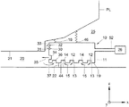
図2は、この発明の実施例によるガスパージシステム10を含むリソグラフィ装置を描く。特に、図2は、パージシステム10をパージフード11を含むように示す。パージシステム10は、パージ容積20内にガスの実質的に層流のパージ流を提供するように構成してある。パージシステム10、特に、パージフード11は、投影システムPLに対するパージフード11の移動をX、YおよびRz方向に典型的に制限するように、堅い結合装置18によって投影システムPLに堅く結合してある。代替実施例では、パージフード11を、基準または計測フレーム(図示せず)のような、リソグラフィ装置の別の部品に堅く結合してもよい。Z方向は、図2に示し、XおよびY軸が形成する平面に垂直な軸である。更に、それは、投影ビームの平均伝播方向にほぼ相当する。Rz方向は、Z軸周りの回転方向を表すための通常の表記法である。パージシステム10は、更に、柔軟な結合装置16によって投影システムPLにZ、RxおよびRy方向に柔軟に結合してあり、このRxおよびRy方向は、図2に示し、それぞれ、XおよびY軸周りの回転方向のための通常の表記法に相当する。代替実施例では、この柔軟な結合装置16を、基準または計測フレーム(図示せず)のような、リソグラフィ装置の別の部品に結合してもよい。
FIG. 2 depicts a lithographic apparatus that includes a
更に、結合装置12、14が、パージフード11を基板W、基板テーブルWT、またはその両方に結合するためにガスベアリング12および任意に、少なくとも部分真空14の形の実現方式で設けてある。以下に更に詳しく議論するように、図2に示す実施例では、このガスベアリングを参照数字12でおよび真空を参照数字14で示す。しかし、特定の実施例に依っては、ガスベアリングおよび真空のそれぞれの位置を交換してもよい。例えば、代替実施例では、パージフード11のパージ容積20側に真空をおよびパージフード11の周囲環境25側にガスベアリングを配置することによって、パージガスが減りまたは周囲環境25へ放出するのを防ぐことができる。これは、リソグラフィ装置のこの環境に放出したパージガスは測定システム、例えば、図1に示す、干渉形式測定システムIFに影響するかも知れないことが分っているので、有利である。或る実施例では、真空リングを設けてパージフードの容積20に最も近い内側縁をシールする。この様にして、ガスがガスベアリングからパージ容積20に入るのを防ぎまたは減らしながら、パージガスを除去することができる。更に、外真空リングを設けてパージフードの外側縁を周囲環境25からシールしてもよい。この様にして、パージガスまたはガスベアリングからのガスを、干渉形式測定システムIFのような敏感な部品がある周囲環境25へ殆どまたは全く放出しないかも知れない。それで、或る実施例では、パージフードの内側縁をシールするように構成した真空結合装置およびパージフードの外側縁をシールするように構成した真空結合装置を真空リングとして配置し構築する。
Furthermore,
ガスは、ガス供給管52によって結合装置12、14へ供給し、排気管53によって排除する。結合装置12、14は、制御要素26、典型的には調整器によって制御する。この制御要素26は、パージシステム10へおよび、任意に、パージシステムからのガス流の流量および/または圧力を制御するために配置してある。典型的には、この制御要素は、パージシステムと基板テーブル、基板、支持構造体、パターニング装置、またはその任意の組合せとの間の結合を制御する。或る実施例で、この制御要素は、このパージ容積を周囲環境から孤立させるように、基板テーブルWT、基板W、支持構造体MT、パターニング装置MA、またはその任意の組合せとパージシステム10の間に最小ガス隙間を提供するように整えてある。
The gas is supplied to the
更に、制御要素26は、パージシステム10と基板テーブルWT、基板W、支持構造体MT、パターニング装置MA、またはその任意の組合せの間に所定のガス隙間をもたらすために、ガスベアリング12がこの結合に与えるガス圧および/または真空を制御することによってこのガスベアリングを制御してもよい。
In addition, the
或る実施例では、パージフード11の中に、少なくとも部分真空または排気装置がガスベアリング12のどちらかの側に設けてあり、即ち、第1排気装置がパージフード11のパージ容積20側の方に配置してあり、更なる排気装置がパージフード11の環境25側の方に配置してあり、およびガスベアリング12がこの第1排気装置と第2排気装置の間に設けてある。この様にして、パージガスが環境25に漏れるのを防ぎまたは減らしながら、ガスベアリングに使うガスのどれも投影システムの一つ以上の光学素子と接触するようになるのを防ぐ。それで、ガスベアリング12に高精製ガスを使う必要がないかも知れない。更に、汚染物質のような、環境影響物がパージ容積20に入るのを防ぎまたは減らすかも知れない。
In some embodiments, at least a partial vacuum or exhaust device is provided in the
或る実施例で、結合装置12、14は、パージフード11と基板W、基板テーブルWT、またはその両方の間でZ、RxおよびRy方向の少なくとも一つに柔軟な結合をもたらす。そのような柔軟な結合を設けることによって、基板Wまたは基板テーブルWTのZ方向のどんな運動もパージフード11が追従することができる。言換えれば、パージフード11は、基板テーブルWTの表面上をZ方向に十分な剛性で浮動し、多分基板テーブルWTおよび、特に、基板Wとのあらゆる有害な衝突を避ける。以下に詳しく説明するように、ガス、例えば、パージガスを基板Wとパージフード11の間のガスベアリングとして使うことによって安定な隙間22を提供する。柔軟な結合12、14の剛性を増すために、少なくとも部分真空14も設けてもよい。この様にして、結合の安定性を増し、パージフードと基板W、基板テーブルWT、またはその両方の間に高い設計許容値なしに安定な隙間22を達成できる。この少なくとも部分真空14は、パージガスを環境に放出できないとき、例えば、リソグラフィ装置の測定システム、例えば、図1に示す、干渉形式測定システムIFに影響するかも知れないので、それを排出するために付加的に使ってもよい。
In some embodiments, the
図2で、パージ容積20は、投影システムPLの一部の近くの領域に設けてある。投影ビームPBが投影システムPLを出るのに通過する投影システムPLの表面21は、パージガスを設ける投影システムPLの特別な部分である。この様にして、投影システムPLの出口面21領域に有り得る汚染物質の濃度を、この投影システムPLの汚染を避けるために低減する。概して、パージフード11と投影システムPLの間の自由空間は、二三ミリメートルのオーダである。図5に更に詳しく示すように、ノズル52を介してパージガスをパージフード11内に噴射する。
In FIG. 2, the
図3は、この発明の更なる実施例によるガスパージシステムを含むリソグラフィ装置を描く。特に、図3では、図2に示した剛性結合18を更なるガスベアリング30、31、32、33で置換えてある。ガス出口32が加圧ガス33の流れをもたらし、ガスベアリングとする。更に、少なくとも部分真空30が設けてあってガス31を排出し、それによって出口32がもたらすベアリングの剛性を増す。それで、堅いガスベアリング30、31、32、33がパージフード11を投影システムPLにX、YおよびRz方向に堅く結合する。更に、以下に更に詳しく説明するように、パージ容積20と環境25の間にシールを設ける。更に、パージ容積20と加圧ガス33の間にシールを設ける。そのような構成は、加圧ガス、例えば、清浄乾燥空気(CDA)の清浄度がパージガス、例えば、浄化CDAのそれに劣る環境では有利かも知れない。それで、この特別の実施例では、清浄でない加圧ガスがパージ容積20を汚染するのを防ぎまたは減少するかも知れない。或る実施例では、特定の用途および必要なベアリングによって、ガスを室30から供給し、室32から排出してもよい。
FIG. 3 depicts a lithographic apparatus including a gas purge system according to a further embodiment of the invention. In particular, in FIG. 3, the
ガス出口34は、パージガス35をパージ容積20の中へ供給する。少なくとも部分真空36がパージ容積20からパージガス37を排出する。図2ではガスベアリング12、14は、単一ガス出口12および少なくとも部分真空14を含むが、図3に示す更なる実施例では、複数のガス出口12および少なくとも部分真空14を備える。この様にして、ガスベアリングの安定性および柔軟性を更に制御できる。更に、パージフード11付近に位置する、測定システムの外乱を最小化でき、およびパージ容積20に使うガスの清浄度の制御をより良く維持するかも知れない。図示する例では、ガス出口12が隙間22に加圧ガス流13をもたらし、一方隣接する少なくとも部分真空入口14がこのガス流の少なくとも一部を15で排出する。同様に、後続のガス出口12が更なるガス流をもたらし、および後続の隣接する少なくとも部分真空入口14がこのガス流の少なくとも一部を15で排出する。図示する例では、二つのガス出口12および二つのガス入口14があるが、ガスベアリング12、14は、一つ以上のガス出口および/またはガス入口を含んでもよい。入口/出口の位置は、周囲ガス17がパージ容積20に入るようになり且つ測定システムに影響するかも知れない環境に放出するのを防ぐように最適化してもよい。
The
ガスベアリング12、14は、パージガス35によってパージされるパージ容積20と環境25の間にシール44を形成してもよい。同様に、ガスベアリング30、31、32、33もパージ容積20と環境25の間にシールを備えてもよい。この様にして、別の状況では、例えば、リソグラフィ装置の他の部品または一般的に環境に与える影響のために、実行できる選択肢ではないかも知れないパージガスを、本発明の実施例に従って、パージ容積20をシールして実質的に密閉したパージ区画室を設けるので、ベアリングガスとして使ってもよい。これらのパージガスは、例えば、有毒ガスまたは干渉計システムの性能を乱すガスでもよい。
The
任意に、図3に示すように、余分な真空室36を設けて、パージガスがガスベアリング真空入口14に入る前にそれらを殆ど除去する。更に、排出したガスをリサイクルしてもよい。
Optionally, as shown in FIG. 3, an
或る実施例では、それぞれ、過圧力および真空を供給する一つまたは二つの室12、14を使う代りに、ガスベアリング、シールおよびパージガスの添加/除去の機能を与えるために、圧力および真空を伴う室の任意のアレイを使ってもよい。或る実施例では、流れの方向を反転するようにこのアレイを配置してもよい。特に、流れをパージ容積20の内側から環境25の方へ向けるようにする。或る実施例では、流れの方向の組合せを用意してもよい。この様にして、選択した流れ方向に依って、例えば、それぞれ、パージガスおよびガスベアリングガスの性質並びに環境によって決るかも知れないユーザの意向に依って、環境からパージ環境へ行くガスまたはパージ環境から環境へ行くガスのシールを効果的に制御してもよい。
In one embodiment, instead of using one or two
室を、均一且つ安定なガスの流れを提供するために基板W、基板テーブルWT、またはその両方に隣接するパージフードの表面19に設けた多孔性材料の領域で置換えてもよい。典型的に、このガスの流れもよく混合する。その様にして、ガスベアリングを更に調整でき、ベアリングの相対剛性および/または柔軟性を制御できる。或る実施例では、これらの室が小さい孔のリングでもよい。そのような構成は、加圧ガス用に使うのに適するかも知れない。或る実施例では、ガスベアリング30、31、32、33を、図2に示すように、剛性結合18で置換える場合、またはパージ容積20と環境25の間のシールを更に改良するために、柔軟なシール46も設けてもよい。
The chamber may be replaced with a region of porous material provided on the
図4は、この発明の実施例によるガスパージシステムの詳細を描く。特に、図4は、基板W、基板テーブルWT、またはその両方に向いた、図2に示すパージフード11の表面19を示す。特に、加圧ガスを供給する領域42がこの表面19に設けてあり、そして、少なくとも部分真空を供給する領域40がこの表面に設けてある。これらの領域40、42は、図4に示すように、リング形でもよい。この様に、真空リングおよびガス供給リングを設けてパージフードを、それぞれ、所望に位置でシールしおよび結合してもよい。先に述べたように、真空リング40は、それぞれ、パージフードの内縁および外縁をシールするために設けてもよい。ガス供給リング42は、パージフードと基板W、基板テーブルWT、またはその両方の間に隙間を形成する。これらのリングは、同心に配置してもよい。或る実施例では、パージガスをパージ容積20の中に噴射し、排気管および/または真空管から除去する。特別な実施例では、最内端真空リング40がパージガス用排出として特に適する。この様にして、パージガスが環境へ漏れるのを防ぎまたは減らす。更に、流れパターンをこの真空リングから加える真空に依って制御できるので、この性能が向上するかも知れない。
FIG. 4 depicts details of a gas purge system according to an embodiment of the present invention. In particular, FIG. 4 shows the
加圧ガスを供給するための領域42は、上記でガス室12とも呼ぶが、加圧ガスを供給する複数のガス出口12を含む。少なくとも部分真空を供給するための領域40は、上記で真空室14とも呼ぶが、ガスを隙間22から排出する複数の入口14を含む。同様に、領域41は、パージガス排気管に相当し、上記で真空室とも呼ぶが、ガスをパージ容積20から排出する複数の入口36を含む。上述のように、領域40、42もまたはその代りに多孔質材料の領域を含んでもよい。多孔性の程度は、所望するガスベアリングに依る。例えば、加圧ガス供給領域42の多孔性は、真空領域40の多孔性より高いかも知れない。図示する実施例では、ガス出口12が典型的にガス入口14より断面積が小さい。この様にして、供給ガスの圧力を正確に制御できる。同様に、入口14に関する出口12の分布も変動するかも知れない。例えば、ベアリングによって供給するガスの圧力を調整するために、入口14に関して高い密度の出口12を設けてもよい。図示する実施例では、ガス出口12の分布がガス入口14の分布とほぼ同じである。基板W、基板テーブルWT、またはその両方に隣接するパージフード11の表面19は、図示する実施例ではほぼ円形である。しかし、表面19の形状は、特定のパージフード11の設計に従って変動してもよい。表面19の中央に設けてあるのは、投影ビームPBが基板Wに入射するようになる前に通過する孔45である。図示する実施例では、この孔45がほぼ円形である。しかし、この孔45は、例えば、投影システムPLが送出する投影ビームおよびパージフード11の設計に従って別の形でもよい。図4に、二つの室の間の領域49を示す。この領域49に、パージフード11および基板/基板テーブルがそれらを分離する隙間22が小さく、互いに接近して配置してある。この様にして、この領域49に高流速が起る。この高流速領域49は、パージフード11と環境25の間のシール効果を更に改善するかも知れない。
The
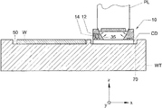
図5ないし図8は、この発明の更なる実施例によるガスパージシステムを含むリソグラフィ装置を描く。図5ないし図7を参照して、例えば走査中に、パージフード11を使用中であるが、一部基板テーブルWTに隣接し且つ一部基板Wに隣接するように配置してもよい。この問題に取組むために、パージフード11に隣接する基板テーブルWTの表面51が、或る実施例では、平坦である。更に、基板テーブルWTの表面51が、或る実施例では、それがパージフード11に隣接するとき、基板Wの表面54とほぼ同じ高さである。即ち、基板テーブルWTの表面の高さと基板Wの表面の高さがほぼ等しい。これは、図5ないし図7に示す実施例では、基板テーブルWTに配置した、基板Wを受けるように構成した窪み50を設けることによって達成する。この窪み50は、深さがZ方向の基板Wの寸法にほぼ等しく、即ち、基板Wの厚さにほぼ等しい。基板Wは、この窪みに配置してある。窪み50は、基板Wがこの窪み50のかなりの部分を満たすように設けてあるが、基板がこの窪み50を完全に満たす必要はない。基板Wの周りの隙間55は、異なるサイズの基板を同じ窪み50に収容できるようにするために、許される。窪み50の側面と基板または基板テーブルの間に漏れが起るかも知れない。そのような漏れは、例えば、パージフード11が基板Wの縁の上を動くとき、周囲大気にパージ容積に入らせるかまたはパージガスにこのパージ容積から漏れ出させるかも知れない。この問題は、窪み50の側面の周りにガス入口/出口のアレイを設け、パージガスをこの窪み50の側面の周りの入口/出口のアレイから吹込みまたは吸出すことによって対応してもよい。更に、図5は、パージガス、ガスベアリングガス、またはその両方を供給するガス供給管52を示す。図示する実施例では、パージガスとガスベアリングガスの両方を同じ供給管52から給する。
5-8 depict a lithographic apparatus including a gas purge system according to a further embodiment of the invention. Referring to FIGS. 5 to 7, for example, the
図6は、リソグラフィ装置が走査および/または露出作業をしている、更なる実施例を示す。走査中、パージフード11は、基板Wの上を動く。一旦基板Wを放射線に露出すると、基板テーブルWT交換が起り、基板が配置してある基板テーブルを更なる基板が配置してある更なる基板テーブルと取替える。この手続を、例えば、二段リソグラフィ装置で行う。その代りに、一旦基板Wの走査を完了すると、それを窪み50から除去してもよい。そこで走査用の次の基板Wを続いて窪み50に配置する。
FIG. 6 shows a further embodiment in which the lithographic apparatus is performing a scanning and / or exposure operation. During scanning, the
図6ないし図8に、基板テーブルWT交換の例を示す。基板テーブルWTを交換するために、パージフード11の真空を任意に除去してもよいが、これは必要ではない。以下に説明するように、閉鎖板を使う実施例に対しては、基板テーブルWTを交換する間典型的には真空を保ち続ける。その上、またはその代りに、図6に示すように、一つ以上のアクチュエータ60が設けてある。アクチュエータ60は、結合装置62によって投影システムPLにおよび更なる結合装置64によってパージフード11に結合する。アクチュエータ60が作動すると、基板テーブルWTの交換を行うべきとき、パージフード11を挙げさせる。或る実施例では、アクチュエータが、必要なとき基板テーブルWTまたは基板Wを交換させるように、磁石装置に選択的にパージフード11を挙げさせるかも知れない。
FIGS. 6 to 8 show examples of substrate table WT replacement. In order to replace the substrate table WT, the vacuum in the
図7は、引継ぎを行うリソグラフィ装置、即ち、基板テーブルWTの交換を行えるように基板テーブルWTを投影システムPLおよびパージシステム10に関して動かす場合を示す。基板テーブルWTの交換中投影システムPLを汚染から保護するために、閉鎖板CDを設けてパージフード11と投影システムPLの間の開口45を覆う。特に、浸漬リソグラフィでは基板テーブルWTの交換中投影システムを湿潤状態に保つために閉鎖板を用意する。閉鎖板を使って、基板テーブルWT交換中、液体、例えば、水を含ませまたは流れ続けさせられる。この閉鎖板CDは、典型的には、基板テーブルWTに配置した更なる窪み70に設ける。基板W同様、窪み70は、深さが閉鎖板CDの厚さにほぼ等しく、それでこの閉鎖板CDを、使用中、窪み70に配置するとき、基板テーブルWTの表面が閉鎖板CDの表面と同じ高さである。或る実施例では、一旦真空を図6で解放し、および任意に、アクチュエータ60を作動させると、基板テーブルWTをパージシステム10が結合してある投影システムPLに関して、図7に示すように、投影システムPLが窪み70に配置してある閉鎖板CDに隣接するような位置へ動かす。或る実施例では、この閉鎖板まで動かすために真空を解放することは必要なく、パージフードを挙げるためにアクチュエータを使うことも必要ない。特に、閉鎖板および基板が基板テーブル表面と同じ高さに配置してある実施例では、それらを一つの側から他の側へ簡単に動かし得る。閉鎖板を拾い上げるためには、加圧ガスを典型的に止める。これは、閉鎖板を然るべき位置にクランプするので、真空が典型的に残り続ける。
FIG. 7 shows the lithographic apparatus performing the takeover, ie the movement of the substrate table WT relative to the projection system PL and the
一旦閉鎖板に隣接する所定の位置になると、少なくとも部分真空14は、閉鎖板CDを、図8に示すように、開口45に吸引させるように作動する。この真空を使って円板CDを基板テーブルWT内のその収納位置から持上げ、それをパージフード11に固定しておく。一旦閉じると、基板テーブルWTを、図8に示すように、除去する。続いて、別の基板テーブルWTを用意する。この閉鎖板CDがパージフード11を閉じ、この様にして基板テーブルWTがないとき高い稀釈率を保証する。これは、基板テーブルWTまたは基板W交換中に投影システムを清浄におよび/または乾かしておくために有用である。
Once in place, adjacent to the closure plate, at least the
この発明は、使用するパージガスに関して限定されないが、上に説明した全ての実施例で、パージガスは、例えば、非常に純粋な窒素N2、またはHe、Ne、Ar、Kr、およびXeのグループから選択したガス、またはこれらのガスのどれかの二つ以上の混合物を含んでもよい。使用するガス組成は、投影ビームの波長のUV放射線に実質的に透明で、或る実施例では、温度および圧力の同じ条件(例えば、標準クリーンルーム条件)の下でおよび同じ波長の放射線を使って測定したときに、空気と実質的に同じ屈折率をものである。或る実施例で、この屈折率は、干渉形式変位測定装置IF(図1に示す)で使う放射線ビームの波長で空気のそれと同じである。マスクおよび/または基板ステージでのパージガスの圧力は、大気圧でもよく、または入ってくる空気でこのシステムが汚されるよりは漏れが生じてもガスの流出になるように、大気圧より高くてもよい。ガスの混合物には、空気、濾過空気、圧搾濾過空気、窒素、および精製CDAがあるが、これに限定されない。 The invention is not limited with respect to the purge gas used, but in all the embodiments described above, the purge gas is selected, for example, from the group of very pure nitrogen N 2 or He, Ne, Ar, Kr, and Xe Or a mixture of two or more of any of these gases. The gas composition used is substantially transparent to UV radiation at the wavelength of the projection beam, and in certain embodiments, under the same conditions of temperature and pressure (eg, standard clean room conditions) and using radiation of the same wavelength When measured, it has substantially the same refractive index as air. In one embodiment, this refractive index is the same as that of air at the wavelength of the radiation beam used in the interferometric displacement measuring device IF (shown in FIG. 1). The pressure of the purge gas at the mask and / or substrate stage may be atmospheric pressure or higher than atmospheric pressure so that there is a leak or gas outflow than the system is contaminated with incoming air. Good. Gas mixtures include, but are not limited to, air, filtered air, compressed filtered air, nitrogen, and purified CDA.
ガスベアリングに使うガスの組成は、パージガスのものと同じまたは類似の性質のものでもよい。ガスベアリングが同じガス組成を使うという必要条件はない。しかし、パージガス用とガスベアリングガス用に同じガス供給を使うならば、別々のガス供給が必要ないかも知れないので、ガス供給が簡単になる。特に、ガスベアリング用にはどんな種類のガス、例えば、窒素、圧搾空気、または濾過圧搾空気を使ってもよい。このガスを供給する圧力は、隙間22の所望の寸法、このパージシステム、特に、パージフードの質量、およびガス出口の面積に依るだろう。このガス圧は、典型的には、6bar以下の範囲にある。他の要因を実質的に一定に保つならば、ガスベアリング出口から送出するガスの圧力が高ければ高いほど、隙間22の寸法が大きい。調整器を設けて、隙間22の十分に正確な寸法を維持するためにガスベアリングを通るガス流を調整する。この様にして、ガスベアリングが柔軟な結合をもたらす。或る実施例では、ガス出口の前のガス体積を増やして、より安定なベアリングを得るために各ガス出口での圧力の均等な分布を保証する。隙間22の寸法は、典型的には約100μm未満である。非浸漬リソグラフィでのZ方向の隙間の典型的寸法は、30〜200μmの範囲内にある。浸漬リソグラフィで、Z方向の隙間22の典型的寸法は、30μmの範囲内にある。特に、約10ないし50μmの間である。しかし、調整器を使って、この隙間の寸法を所望の運転条件に従って変えることができ、その条件は、例えば、一つの基板内かまたは異なる厚さの異なる基板間の基板の表面平坦度によって決り得る。従来のエアベアリングでのこの隙間の典型的寸法は、8〜15μmのオーダである。
The composition of the gas used in the gas bearing may be of the same or similar nature as that of the purge gas. There is no requirement that gas bearings use the same gas composition. However, if the same gas supply is used for the purge gas and the gas bearing gas, the gas supply is simplified because a separate gas supply may not be required. In particular, any type of gas may be used for the gas bearing, such as nitrogen, compressed air, or filtered compressed air. The pressure at which this gas is supplied will depend on the desired size of the
約6barのガス圧に対する、ガスベアリング12、14の加圧ガスに加えて少なくとも部分真空を用意する実施例では、−0.4〜−0.8barの近似範囲の真空を用意する。この必要な真空は、特定のパージフード11に関して所望のガスベアリングおよびこのパージフードと基板テーブルWT、基板W、またはその両方の間に維持すべき隙間22に依ることが分るだろう。
In an embodiment where at least a partial vacuum is provided in addition to the pressurized gas of the
これらの図に示す実施例では、基板ステージ付近で使うためのパージシステムを示し、説明する。しかし、その上、本発明の実施例は、レチクルステージMT、即ち、パターニング装置MA用の支持構造体MTに用途がある。それで、更なる実施例では、ガスパージシステム10をパージ容積20にガスを提供するために用意し、このパージ容積20は、照明システムILの少なくとも一部を含む。パージシステム10を支持構造体MTおよび/またはパターニング装置MAに結合するために結合装置を設けてもよい。この様にして、基板ステージに関して説明した利点をマスクステージMTとも共有してよい。
In the embodiments shown in these figures, a purge system for use near the substrate stage is shown and described. In addition, however, embodiments of the present invention find use in reticle stage MT, ie, support structure MT for patterning device MA. Thus, in a further embodiment, a
或る実施例では、支持構造体MTおよび/またはパターニング装置MAが第1および第2の異なる方向が定める区域に配置してある。パージシステム10は、この区域に対してある角度を成して伸びる第3方向でこの支持構造体MTおよび/またはパターニング装置MAに結合してある。或る実施例で、このパージシステムは、支持構造体MTおよび/またはパターニング装置MAにこの第3方向、この第1方向周りの回転方向、この第2方向周りの回転方向、またはその任意の組合せで柔軟に結合してある。或る実施例で、このパージシステム10は、照明システムILに第1方向、第2方向、この第3方向周りの回転方向、またはその任意の組合せで堅く結合してある。
In one embodiment, the support structure MT and / or the patterning device MA are arranged in areas defined by first and second different directions. The
或る実施例では、支持構造体MTは、パターニング装置を受けるように構成した窪みを備え、例えば、その窪みは、深さがこのパターニング装置の厚さにほぼ等しい。或る実施例で、この窪みは、この窪みの周辺の周りに拡がる縁を有し、この装置は、更に、パージフードがこのパターニング装置の縁の上を動くとき、ガスがパージ容積へまたはパージ容積から漏れるのを防ぐために、この窪みの縁の周りに設けたガス入口および/またはガス出口の配列を含む。或る実施例で、投影ビームを受けるように構成したパターニング装置MAの表面は、支持構造体MTの表面と同じ高さである。或る実施例で、このガスベアリングは、使用中、投影ビームを受けるように構成したパターニング装置の表面とパージシステムの間に安定な隙間をもたらす。或る実施例で、このガスベアリングは、投影ビームを受けるように構成したパターニング装置の表面とパージシステムの間の隙間の寸法を制御するために、ガスの流量および/または圧力を調整するための制御要素、典型的には調整器を含む。特に、このガスベアリングは、このパージシステムがパターニング装置、支持構造体、またはその両方の表面の上を、この支持構造体が配置してある第1および第2方向が定める区域にある角度で置かれた第3方向に十分な剛性で、浮動するように、この結合にガスを供給するためのガス供給、この結合からガスを除去するための少なくとも部分真空、およびこのガス供給およびこの少なくとも部分真空を合同して制御するように構成した制御要素を含む。 In certain embodiments, the support structure MT includes a recess configured to receive the patterning device, for example, the recess is approximately equal in depth to the thickness of the patterning device. In some embodiments, the recess has an edge that extends around the periphery of the recess, and the apparatus further includes gas to or from the purge volume as the purge hood moves over the edge of the patterning device. In order to prevent leakage from the volume, an arrangement of gas inlets and / or gas outlets provided around the edge of the recess is included. In some embodiments, the surface of the patterning device MA configured to receive the projection beam is flush with the surface of the support structure MT. In some embodiments, the gas bearing provides a stable clearance between the surface of the patterning device configured to receive the projection beam and the purge system during use. In some embodiments, the gas bearing is for adjusting the flow rate and / or pressure of the gas to control the size of the gap between the surface of the patterning device configured to receive the projection beam and the purge system. It includes a control element, typically a regulator. In particular, the gas bearing is positioned at an angle where the purge system is above the patterning device, the support structure, or both, in an area defined by first and second directions in which the support structure is located. A gas supply to supply gas to the bond, at least a partial vacuum to remove gas from the bond, and a gas supply and the at least partial vacuum to float with sufficient rigidity in the third direction The control element comprised so that it may control jointly is included.
或る実施例では、このパージシステムは、パージフードを含み、このパージフードは、支持構造体および/またはパターニング装置に結合してある。或る実施例で、このパージシステムは、パージフードを含み、このガスベアリングは、このパージフードを第3方向に挙げるように構成したアクチュエータを含み、この第3方向は、支持構造体が配置してある区域にある角度の方向に伸びる。この装置は、更に、結合装置に関連して、このパージフードを、支持構造体が配置してある区域にある角度の方向に伸びる第3方向に挙げさせるように構成したアクチュエータを含んでもよい。このアクチュエータは、磁石にパージフード11を挙げさせてもよい。パージシステムと支持構造体および/またはパターニング装置の間の結合を制御するために、制御要素も設けてもよい。特に、この結合装置は、ガスベアリングおよび、このパージ容積を周囲環境から孤立させるように、支持構造体および/またはパターニング装置とパージシステムの間に最小ガス隙間をもたらすように構成した制御要素を含んでもよい。
In some embodiments, the purge system includes a purge hood that is coupled to the support structure and / or patterning device. In one embodiment, the purge system includes a purge hood, and the gas bearing includes an actuator configured to raise the purge hood in a third direction, wherein the support structure is disposed in the third direction. It extends in the direction of an angle in a certain area. The apparatus may further include an actuator configured in connection with the coupling device to cause the purge hood to be raised in a third direction extending in a direction of an angle in the area where the support structure is located. In this actuator, the magnet may include the
本発明の特定の実施例を上に説明したが、本発明を説明した以外の方法で実施してもよいことが分るだろう。この説明は、本発明を限定することを意図しない。 While specific embodiments of the invention have been described above, it will be appreciated that the invention may be practiced otherwise than as described. This description is not intended to limit the invention.
10 流体供給システム、液体供給システム、ガスパージシステム
11 パージフード
12 結合装置、ガスベアリング
14 結合装置、ガスベアリング
20 容積、パージ容積
22 隙間
25 周囲環境、外部環境
26 制御要素
44 シール
46 シール
50 窪み
60 アクチュエータ
C 目標部分
IL 照明システム
MA パターニング装置
MT 支持構造体
PL 投影システム
W 基板
WT 基板テーブル
DESCRIPTION OF
Claims (40)
放射線のビームの断面にパターンを与えるのに役立つパターニング装置を保持するように構成した支持構造体、
基板を保持するように構成した基板テーブル、
パターン化したビームをこの基板の目標部分上に投影するように構成した投影システム、
該投影システムの少なくとも一部、照明システムの少なくとも一部、またはその両方を含む容積に流体を提供するように構成した流体供給システム、および
この流体供給システムをこの基板テーブル、基板、支持構造体、パターニング装置、またはその任意の組合せに結合するように構成した結合装置、を含むリソグラフィ装置。 An illumination system configured to regulate the beam of radiation,
A support structure configured to hold a patterning device that serves to pattern the cross-section of the beam of radiation;
A substrate table configured to hold a substrate;
A projection system configured to project a patterned beam onto a target portion of the substrate;
A fluid supply system configured to provide fluid to a volume including at least a portion of the projection system, at least a portion of the illumination system, or both; and the fluid supply system comprising the substrate table, the substrate, a support structure, A lithographic apparatus, comprising: a patterning device, or a coupling device configured to couple to any combination thereof.
パターン化した放射線のビームをリソグラフィ装置の投影システムを使って基板の目標部分上に投影する工程、
流体供給システムを使って流体を、この投影システムの少なくとも一部、照明システムの少なくとも一部、またはその両方を含む容積に提供する工程、および
この流体供給システムをこの基板、この基板を保持する基板テーブル、このパターン化したビームを作るために使うパターニング装置、このパターニング装置を保持する支持構造体、またはその任意の組合せに結合する工程、を含む方法。 A device manufacturing method comprising:
Projecting a patterned beam of radiation onto a target portion of a substrate using a projection system of a lithographic apparatus;
Providing a fluid to a volume containing at least a portion of the projection system, at least a portion of the illumination system, or both using a fluid supply system; and the substrate for holding the substrate, the substrate Coupling to a table, a patterning device used to create the patterned beam, a support structure holding the patterning device, or any combination thereof.
Applications Claiming Priority (1)
| Application Number | Priority Date | Filing Date | Title |
|---|---|---|---|
| US10/873,650 US7057702B2 (en) | 2004-06-23 | 2004-06-23 | Lithographic apparatus and device manufacturing method |
Related Child Applications (1)
| Application Number | Title | Priority Date | Filing Date |
|---|---|---|---|
| JP2007300911A Division JP5064979B2 (en) | 2004-06-23 | 2007-11-20 | Lithographic apparatus and device manufacturing method |
Publications (2)
| Publication Number | Publication Date |
|---|---|
| JP2006013502A true JP2006013502A (en) | 2006-01-12 |
| JP2006013502A5 JP2006013502A5 (en) | 2007-08-09 |
Family
ID=34938361
Family Applications (2)
| Application Number | Title | Priority Date | Filing Date |
|---|---|---|---|
| JP2005181472A Pending JP2006013502A (en) | 2004-06-23 | 2005-06-22 | Lithographic apparatus and device manufacturing method |
| JP2007300911A Expired - Fee Related JP5064979B2 (en) | 2004-06-23 | 2007-11-20 | Lithographic apparatus and device manufacturing method |
Family Applications After (1)
| Application Number | Title | Priority Date | Filing Date |
|---|---|---|---|
| JP2007300911A Expired - Fee Related JP5064979B2 (en) | 2004-06-23 | 2007-11-20 | Lithographic apparatus and device manufacturing method |
Country Status (7)
| Country | Link |
|---|---|
| US (1) | US7057702B2 (en) |
| EP (1) | EP1610183A3 (en) |
| JP (2) | JP2006013502A (en) |
| KR (1) | KR100695553B1 (en) |
| CN (2) | CN1713075B (en) |
| SG (2) | SG118391A1 (en) |
| TW (1) | TWI277837B (en) |
Cited By (4)
| Publication number | Priority date | Publication date | Assignee | Title |
|---|---|---|---|---|
| JP2012182450A (en) * | 2011-02-28 | 2012-09-20 | Asml Netherlands Bv | Fluid handling structure, lithography apparatus and manufacturing method of device |
| JP2015522843A (en) * | 2012-07-06 | 2015-08-06 | エーエスエムエル ネザーランズ ビー.ブイ. | Lithographic apparatus |
| KR20190043168A (en) * | 2016-08-30 | 2019-04-25 | 상하이 마이크로 일렉트로닉스 이큅먼트(그룹) 컴퍼니 리미티드 | Apparatus and method for preventing lens contamination |
| US10983448B2 (en) | 2017-07-21 | 2021-04-20 | Shanghai Micro Electronics Equipment (Group) Co., Ltd. | Objective lens protection device, objective lens system and lithographic device |
Families Citing this family (37)
| Publication number | Priority date | Publication date | Assignee | Title |
|---|---|---|---|---|
| JP3977324B2 (en) | 2002-11-12 | 2007-09-19 | エーエスエムエル ネザーランズ ビー.ブイ. | Lithographic apparatus |
| WO2004090634A2 (en) * | 2003-04-10 | 2004-10-21 | Nikon Corporation | Environmental system including vaccum scavange for an immersion lithography apparatus |
| EP1611486B1 (en) | 2003-04-10 | 2016-03-16 | Nikon Corporation | Environmental system including a transport region for an immersion lithography apparatus |
| SG139736A1 (en) | 2003-04-11 | 2008-02-29 | Nikon Corp | Apparatus having an immersion fluid system configured to maintain immersion fluid in a gap adjacent an optical assembly |
| TWI442694B (en) * | 2003-05-30 | 2014-06-21 | Asml Netherlands Bv | Lithographic apparatus and device manufacturing method |
| KR101931923B1 (en) | 2003-06-19 | 2018-12-21 | 가부시키가이샤 니콘 | Exposure device and device producing method |
| EP1703548B1 (en) * | 2004-01-05 | 2010-05-12 | Nikon Corporation | Exposure apparatus, exposure method, and device producing method |
| US7589822B2 (en) | 2004-02-02 | 2009-09-15 | Nikon Corporation | Stage drive method and stage unit, exposure apparatus, and device manufacturing method |
| KR101250155B1 (en) | 2004-03-25 | 2013-04-05 | 가부시키가이샤 니콘 | Exposure apparatus and method for manufacturing device |
| US7486381B2 (en) | 2004-05-21 | 2009-02-03 | Asml Netherlands B.V. | Lithographic apparatus and device manufacturing method |
| US7522261B2 (en) * | 2004-09-24 | 2009-04-21 | Asml Netherlands B.V. | Lithographic apparatus and device manufacturing method |
| US7119876B2 (en) * | 2004-10-18 | 2006-10-10 | Asml Netherlands B.V. | Lithographic apparatus and device manufacturing method |
| US7583357B2 (en) * | 2004-11-12 | 2009-09-01 | Asml Netherlands B.V. | Lithographic apparatus and device manufacturing method |
| US20070132976A1 (en) * | 2005-03-31 | 2007-06-14 | Nikon Corporation | Exposure apparatus, exposure method, and method for producing device |
| US7411654B2 (en) * | 2005-04-05 | 2008-08-12 | Asml Netherlands B.V. | Lithographic apparatus and device manufacturing method |
| US7834974B2 (en) | 2005-06-28 | 2010-11-16 | Asml Netherlands B.V. | Lithographic apparatus and device manufacturing method |
| US7170583B2 (en) * | 2005-06-29 | 2007-01-30 | Asml Netherlands B.V. | Lithographic apparatus immersion damage control |
| US7432513B2 (en) * | 2005-10-21 | 2008-10-07 | Asml Netherlands B.V. | Gas shower, lithographic apparatus and use of a gas shower |
| US8125610B2 (en) | 2005-12-02 | 2012-02-28 | ASML Metherlands B.V. | Method for preventing or reducing contamination of an immersion type projection apparatus and an immersion type lithographic apparatus |
| US7728952B2 (en) * | 2007-01-25 | 2010-06-01 | Taiwan Semiconductor Manufacturing Company, Ltd. | Method and system for closing plate take-over in immersion lithography |
| US8654305B2 (en) * | 2007-02-15 | 2014-02-18 | Asml Holding N.V. | Systems and methods for insitu lens cleaning in immersion lithography |
| US8817226B2 (en) * | 2007-02-15 | 2014-08-26 | Asml Holding N.V. | Systems and methods for insitu lens cleaning using ozone in immersion lithography |
| NL1035908A1 (en) | 2007-09-25 | 2009-03-26 | Asml Netherlands Bv | Lithographic apparatus and device manufacturing method. |
| JP2009094145A (en) * | 2007-10-04 | 2009-04-30 | Canon Inc | Exposure device and method, and device manufacturing method |
| NL2005586A (en) * | 2009-12-02 | 2011-06-06 | Asml Netherlands Bv | Lithographic apparatus and sealing device for a lithographic apparatus. |
| EP2381310B1 (en) | 2010-04-22 | 2015-05-06 | ASML Netherlands BV | Fluid handling structure and lithographic apparatus |
| WO2012027406A2 (en) * | 2010-08-24 | 2012-03-01 | Nikon Corporation | Vacuum chamber assembly for supporting a workpiece |
| NL2008695A (en) | 2011-05-25 | 2012-11-27 | Asml Netherlands Bv | Lithographic apparatus comprising substrate table. |
| JP5809364B2 (en) * | 2011-11-22 | 2015-11-10 | エーエスエムエル ネザーランズ ビー.ブイ. | Exposure equipment |
| US9568828B2 (en) * | 2012-10-12 | 2017-02-14 | Nikon Corporation | Exposure apparatus, exposing method, device manufacturing method, program, and recording medium |
| NL2014893A (en) * | 2014-07-04 | 2016-03-31 | Asml Netherlands Bv | Lithographic apparatus and a method of manufacturing a device using a lithographic apparatus. |
| US11397385B2 (en) | 2016-06-17 | 2022-07-26 | Taiwan Semiconductor Manufacturing Company, Ltd | Apparatus and a method of forming a particle shield |
| EP3620858B1 (en) * | 2018-09-10 | 2023-11-01 | Canon Kabushiki Kaisha | Exposure apparatus and method of manufacturing article |
| JP2022544905A (en) * | 2019-08-20 | 2022-10-24 | エーエスエムエル ネザーランズ ビー.ブイ. | Substrate holder, lithographic apparatus and method |
| EP3919978A1 (en) * | 2020-06-05 | 2021-12-08 | Taiwan Semiconductor Manufacturing Co., Ltd. | Apparatus and a method of forming a particle shield |
| US11740564B2 (en) * | 2020-06-18 | 2023-08-29 | Taiwan Semiconductor Manufacturing Company, Ltd. | Lithography apparatus and method using the same |
| CN113262956B (en) * | 2021-07-21 | 2021-10-15 | 四川洪芯微科技有限公司 | Semiconductor wafer surface treatment device |
Family Cites Families (13)
| Publication number | Priority date | Publication date | Assignee | Title |
|---|---|---|---|---|
| JPS57153433A (en) * | 1981-03-18 | 1982-09-22 | Hitachi Ltd | Manufacturing device for semiconductor |
| US5900354A (en) * | 1997-07-03 | 1999-05-04 | Batchelder; John Samuel | Method for optical inspection and lithography |
| EP1041605A4 (en) * | 1997-08-29 | 2005-09-21 | Nikon Corp | Temperature adjusting method and aligner to which this method is applied |
| AU4653999A (en) * | 1999-07-16 | 2001-02-05 | Nikon Corporation | Exposure method and system |
| WO2001084241A1 (en) * | 2000-05-03 | 2001-11-08 | Silicon Valley Group, Inc. | Non-contact seal using purge gas |
| JP2001358056A (en) * | 2000-06-15 | 2001-12-26 | Canon Inc | Exposure apparatus |
| TWI222668B (en) * | 2001-12-21 | 2004-10-21 | Nikon Corp | Gas purging method and exposure system, and device production method |
| US6788477B2 (en) * | 2002-10-22 | 2004-09-07 | Taiwan Semiconductor Manufacturing Co., Ltd. | Apparatus for method for immersion lithography |
| EP1420298B1 (en) | 2002-11-12 | 2013-02-20 | ASML Netherlands B.V. | Lithographic apparatus |
| DE60335595D1 (en) * | 2002-11-12 | 2011-02-17 | Asml Netherlands Bv | Immersion lithographic apparatus and method of making a device |
| EP1429188B1 (en) * | 2002-11-12 | 2013-06-19 | ASML Netherlands B.V. | Lithographic projection apparatus |
| SG2011031200A (en) * | 2002-12-10 | 2014-09-26 | Nippon Kogaku Kk | Exposure apparatus and device manufacturing method |
| EP1503244A1 (en) * | 2003-07-28 | 2005-02-02 | ASML Netherlands B.V. | Lithographic projection apparatus and device manufacturing method |
-
2004
- 2004-06-23 US US10/873,650 patent/US7057702B2/en active Active
-
2005
- 2005-06-20 SG SG200503932A patent/SG118391A1/en unknown
- 2005-06-20 SG SG200718993-9A patent/SG138618A1/en unknown
- 2005-06-22 TW TW094120867A patent/TWI277837B/en not_active IP Right Cessation
- 2005-06-22 JP JP2005181472A patent/JP2006013502A/en active Pending
- 2005-06-23 KR KR1020050054233A patent/KR100695553B1/en not_active IP Right Cessation
- 2005-06-23 CN CN200510079476.XA patent/CN1713075B/en not_active Expired - Fee Related
- 2005-06-23 EP EP05076479A patent/EP1610183A3/en not_active Withdrawn
- 2005-06-23 CN CN2010102497928A patent/CN101916050B/en not_active Expired - Fee Related
-
2007
- 2007-11-20 JP JP2007300911A patent/JP5064979B2/en not_active Expired - Fee Related
Cited By (8)
| Publication number | Priority date | Publication date | Assignee | Title |
|---|---|---|---|---|
| JP2012182450A (en) * | 2011-02-28 | 2012-09-20 | Asml Netherlands Bv | Fluid handling structure, lithography apparatus and manufacturing method of device |
| US8830441B2 (en) | 2011-02-28 | 2014-09-09 | Asml Netherlands B.V. | Fluid handling structure, a lithographic apparatus and a device manufacturing method |
| JP2015522843A (en) * | 2012-07-06 | 2015-08-06 | エーエスエムエル ネザーランズ ビー.ブイ. | Lithographic apparatus |
| US9513568B2 (en) | 2012-07-06 | 2016-12-06 | Asml Netherlands B.V. | Lithographic apparatus |
| US10788763B2 (en) | 2012-07-06 | 2020-09-29 | Asml Netherlands B.V. | Lithographic apparatus |
| KR20190043168A (en) * | 2016-08-30 | 2019-04-25 | 상하이 마이크로 일렉트로닉스 이큅먼트(그룹) 컴퍼니 리미티드 | Apparatus and method for preventing lens contamination |
| KR102212629B1 (en) * | 2016-08-30 | 2021-02-04 | 상하이 마이크로 일렉트로닉스 이큅먼트(그룹) 컴퍼니 리미티드 | Lens contamination prevention device and method |
| US10983448B2 (en) | 2017-07-21 | 2021-04-20 | Shanghai Micro Electronics Equipment (Group) Co., Ltd. | Objective lens protection device, objective lens system and lithographic device |
Also Published As
| Publication number | Publication date |
|---|---|
| SG118391A1 (en) | 2006-01-27 |
| KR20060048484A (en) | 2006-05-18 |
| TW200612207A (en) | 2006-04-16 |
| JP5064979B2 (en) | 2012-10-31 |
| KR100695553B1 (en) | 2007-03-14 |
| CN101916050B (en) | 2013-11-20 |
| US7057702B2 (en) | 2006-06-06 |
| JP2008072139A (en) | 2008-03-27 |
| CN1713075A (en) | 2005-12-28 |
| TWI277837B (en) | 2007-04-01 |
| SG138618A1 (en) | 2008-01-28 |
| EP1610183A2 (en) | 2005-12-28 |
| CN101916050A (en) | 2010-12-15 |
| US20050286032A1 (en) | 2005-12-29 |
| CN1713075B (en) | 2010-08-04 |
| EP1610183A3 (en) | 2007-10-31 |
Similar Documents
| Publication | Publication Date | Title |
|---|---|---|
| JP5064979B2 (en) | Lithographic apparatus and device manufacturing method | |
| US9182679B2 (en) | Lithographic apparatus and device manufacturing method | |
| JP4322865B2 (en) | Lithographic apparatus and device manufacturing method | |
| JP4939283B2 (en) | Lithographic apparatus and device manufacturing method | |
| KR101234684B1 (en) | Lithographic apparatus and device manufacturing method | |
| KR100730056B1 (en) | Lithographic apparatus, reticle exchange unit and device manufacturing method | |
| JP2008131041A (en) | Lithographic equipment and method for manufacturing device |
Legal Events
| Date | Code | Title | Description |
|---|---|---|---|
| RD03 | Notification of appointment of power of attorney |
Free format text: JAPANESE INTERMEDIATE CODE: A7423 Effective date: 20060904 |
|
| RD05 | Notification of revocation of power of attorney |
Free format text: JAPANESE INTERMEDIATE CODE: A7425 Effective date: 20070313 |
|
| A521 | Request for written amendment filed |
Free format text: JAPANESE INTERMEDIATE CODE: A523 Effective date: 20070516 |
|
| A521 | Request for written amendment filed |
Free format text: JAPANESE INTERMEDIATE CODE: A523 Effective date: 20070627 |
|
| A871 | Explanation of circumstances concerning accelerated examination |
Free format text: JAPANESE INTERMEDIATE CODE: A871 Effective date: 20070627 |
|
| A975 | Report on accelerated examination |
Free format text: JAPANESE INTERMEDIATE CODE: A971005 Effective date: 20070713 |
|
| A131 | Notification of reasons for refusal |
Free format text: JAPANESE INTERMEDIATE CODE: A131 Effective date: 20070720 |
|
| A601 | Written request for extension of time |
Free format text: JAPANESE INTERMEDIATE CODE: A601 Effective date: 20071019 |
|
| A602 | Written permission of extension of time |
Free format text: JAPANESE INTERMEDIATE CODE: A602 Effective date: 20071024 |
|
| A521 | Request for written amendment filed |
Free format text: JAPANESE INTERMEDIATE CODE: A523 Effective date: 20071120 |
|
| A02 | Decision of refusal |
Free format text: JAPANESE INTERMEDIATE CODE: A02 Effective date: 20071219 |
|
| A521 | Request for written amendment filed |
Free format text: JAPANESE INTERMEDIATE CODE: A523 Effective date: 20080416 |
|
| A521 | Request for written amendment filed |
Free format text: JAPANESE INTERMEDIATE CODE: A523 Effective date: 20080416 |
|
| A911 | Transfer to examiner for re-examination before appeal (zenchi) |
Free format text: JAPANESE INTERMEDIATE CODE: A911 Effective date: 20080423 |
|
| A912 | Re-examination (zenchi) completed and case transferred to appeal board |
Free format text: JAPANESE INTERMEDIATE CODE: A912 Effective date: 20080516 |
|
| A601 | Written request for extension of time |
Free format text: JAPANESE INTERMEDIATE CODE: A601 Effective date: 20090116 |
|
| A602 | Written permission of extension of time |
Free format text: JAPANESE INTERMEDIATE CODE: A602 Effective date: 20090122 |