JP2005536726A - Acoustic inspection device - Google Patents
Acoustic inspection device Download PDFInfo
- Publication number
- JP2005536726A JP2005536726A JP2004529887A JP2004529887A JP2005536726A JP 2005536726 A JP2005536726 A JP 2005536726A JP 2004529887 A JP2004529887 A JP 2004529887A JP 2004529887 A JP2004529887 A JP 2004529887A JP 2005536726 A JP2005536726 A JP 2005536726A
- Authority
- JP
- Japan
- Prior art keywords
- inspection apparatus
- transducer
- unit
- computer
- pulse
- Prior art date
- Legal status (The legal status is an assumption and is not a legal conclusion. Google has not performed a legal analysis and makes no representation as to the accuracy of the status listed.)
- Pending
Links
Images


Classifications
-
- G—PHYSICS
- G01—MEASURING; TESTING
- G01N—INVESTIGATING OR ANALYSING MATERIALS BY DETERMINING THEIR CHEMICAL OR PHYSICAL PROPERTIES
- G01N29/00—Investigating or analysing materials by the use of ultrasonic, sonic or infrasonic waves; Visualisation of the interior of objects by transmitting ultrasonic or sonic waves through the object
- G01N29/34—Generating the ultrasonic, sonic or infrasonic waves, e.g. electronic circuits specially adapted therefor
- G01N29/348—Generating the ultrasonic, sonic or infrasonic waves, e.g. electronic circuits specially adapted therefor with frequency characteristics, e.g. single frequency signals, chirp signals
-
- G—PHYSICS
- G01—MEASURING; TESTING
- G01N—INVESTIGATING OR ANALYSING MATERIALS BY DETERMINING THEIR CHEMICAL OR PHYSICAL PROPERTIES
- G01N29/00—Investigating or analysing materials by the use of ultrasonic, sonic or infrasonic waves; Visualisation of the interior of objects by transmitting ultrasonic or sonic waves through the object
- G01N29/02—Analysing fluids
- G01N29/024—Analysing fluids by measuring propagation velocity or propagation time of acoustic waves
-
- G—PHYSICS
- G01—MEASURING; TESTING
- G01N—INVESTIGATING OR ANALYSING MATERIALS BY DETERMINING THEIR CHEMICAL OR PHYSICAL PROPERTIES
- G01N29/00—Investigating or analysing materials by the use of ultrasonic, sonic or infrasonic waves; Visualisation of the interior of objects by transmitting ultrasonic or sonic waves through the object
- G01N29/04—Analysing solids
- G01N29/06—Visualisation of the interior, e.g. acoustic microscopy
- G01N29/0609—Display arrangements, e.g. colour displays
-
- G—PHYSICS
- G01—MEASURING; TESTING
- G01N—INVESTIGATING OR ANALYSING MATERIALS BY DETERMINING THEIR CHEMICAL OR PHYSICAL PROPERTIES
- G01N29/00—Investigating or analysing materials by the use of ultrasonic, sonic or infrasonic waves; Visualisation of the interior of objects by transmitting ultrasonic or sonic waves through the object
- G01N29/04—Analysing solids
- G01N29/07—Analysing solids by measuring propagation velocity or propagation time of acoustic waves
-
- G—PHYSICS
- G01—MEASURING; TESTING
- G01N—INVESTIGATING OR ANALYSING MATERIALS BY DETERMINING THEIR CHEMICAL OR PHYSICAL PROPERTIES
- G01N29/00—Investigating or analysing materials by the use of ultrasonic, sonic or infrasonic waves; Visualisation of the interior of objects by transmitting ultrasonic or sonic waves through the object
- G01N29/22—Details, e.g. general constructional or apparatus details
- G01N29/222—Constructional or flow details for analysing fluids
-
- G—PHYSICS
- G01—MEASURING; TESTING
- G01N—INVESTIGATING OR ANALYSING MATERIALS BY DETERMINING THEIR CHEMICAL OR PHYSICAL PROPERTIES
- G01N29/00—Investigating or analysing materials by the use of ultrasonic, sonic or infrasonic waves; Visualisation of the interior of objects by transmitting ultrasonic or sonic waves through the object
- G01N29/22—Details, e.g. general constructional or apparatus details
- G01N29/223—Supports, positioning or alignment in fixed situation
-
- G—PHYSICS
- G01—MEASURING; TESTING
- G01N—INVESTIGATING OR ANALYSING MATERIALS BY DETERMINING THEIR CHEMICAL OR PHYSICAL PROPERTIES
- G01N29/00—Investigating or analysing materials by the use of ultrasonic, sonic or infrasonic waves; Visualisation of the interior of objects by transmitting ultrasonic or sonic waves through the object
- G01N29/22—Details, e.g. general constructional or apparatus details
- G01N29/32—Arrangements for suppressing undesired influences, e.g. temperature or pressure variations, compensating for signal noise
- G01N29/326—Arrangements for suppressing undesired influences, e.g. temperature or pressure variations, compensating for signal noise compensating for temperature variations
-
- G—PHYSICS
- G01—MEASURING; TESTING
- G01N—INVESTIGATING OR ANALYSING MATERIALS BY DETERMINING THEIR CHEMICAL OR PHYSICAL PROPERTIES
- G01N2291/00—Indexing codes associated with group G01N29/00
- G01N2291/02—Indexing codes associated with the analysed material
- G01N2291/028—Material parameters
- G01N2291/02881—Temperature
-
- G—PHYSICS
- G01—MEASURING; TESTING
- G01N—INVESTIGATING OR ANALYSING MATERIALS BY DETERMINING THEIR CHEMICAL OR PHYSICAL PROPERTIES
- G01N2291/00—Indexing codes associated with group G01N29/00
- G01N2291/04—Wave modes and trajectories
- G01N2291/044—Internal reflections (echoes), e.g. on walls or defects
Abstract
【課題】液体または固体のバルク物質を収容する(密封または非密封)容器を試験するように特に適合された超音波検査装置を提供する。
【解決手段】この装置は、全体として手持ちピストルの形状をなし、トランスデューサの前側接触面が容器の前壁に位置決めされる。この装置から送信された超音波パルスは、調査中の容器の後壁から反射する。受信したエコーパルスをデジタル波形に変換する。この波形を、温度、パルスの移動距離および移動時間に関して解析して、この液体その他の物質の特徴を確認し、それによって容器内の物質を特定する。An ultrasonic inspection apparatus is particularly adapted to test containers (sealed or unsealed) containing liquid or solid bulk material.
The device is generally in the form of a hand-held pistol, and the front contact surface of the transducer is positioned on the front wall of the container. Ultrasonic pulses transmitted from this device are reflected from the rear wall of the container under investigation. The received echo pulse is converted into a digital waveform. This waveform is analyzed with respect to temperature, pulse travel distance and travel time to identify the characteristics of this liquid or other material, thereby identifying the material in the container.
Description
本発明は、超音波検査に関し、より詳細には、超音波を利用した非侵入・非侵襲音響検査用の装置および方法に関する。 The present invention relates to ultrasonic inspection, and more particularly to an apparatus and method for non-invasive and non-invasive acoustic inspection using ultrasonic waves.
本発明は、米国エネルギー省と締結した契約第DE−AC0676RLO1830号を受け、政府援助によって行われた。政府は、本発明の一定の権利を有する。 This invention was made with government support under Contract DE-AC0676RLO1830 signed with the US Department of Energy. The government has certain rights in the invention.
多くの業界では、容器(container)の内容物を確認することが望ましいか、または必要であり、それらの応用例は国内外に存在する。国内の応用例は極めて多く、例えば、法執行、軍事、ボーダーコントロール、輸送・出荷などがそうである。国際社会では、国境検査、訓練および条約協定の活動が際立った応用例である。他の応用例には、不法な薬物の製造および密輸を防ぎ、租税および関税を徴収し、在庫を効果的に維持し、条約の遵守を検証しかつ確実にするための活動が含まれる。さらに、所与の産業におけるニーズは、広範かつ複雑に多様化している。例えば、食品加工から化学製品の在庫管理に至る各産業において、材料の品質および加工管理は、製品の性能および安全性の高い基準を実現するための中核をなすものである。 In many industries, it is desirable or necessary to check the contents of containers, and their applications exist both at home and abroad. There are numerous domestic applications such as law enforcement, military, border control, transportation and shipping. In the international community, border inspection, training and treaty agreement activities are prominent applications. Other applications include activities to prevent illegal drug production and smuggling, collect taxes and customs duties, effectively maintain inventory, verify and ensure compliance with the Convention. Furthermore, the needs in a given industry are extensive and complex. For example, in industries ranging from food processing to chemical product inventory management, material quality and process control are central to achieving high standards of product performance and safety.
国内外の境界線を越えて輸送されるものを含めて、国内外ともに大量の容器が出荷されるので、容器を非侵入的に取り調べるための比較的高速かつ効果的な方法が特に求められている。望ましくは、この取調べは、容器内の物質(例えば、液体、固体、バルク物質など)を特定するだけでなく、容器内に入っていないはずの物体の存在を確認することができるように実施し得るべきである。例えば、密輸品を含む梱包物が、液体の容器内に隠蔽されて、すなわち沈められて、あるいはその他の方法でバルク物質中に隠されて国境を越えて密輸されることがある。 Large quantities of containers are shipped both domestically and abroad, including those that are transported across national and international boundaries, and there is a particular need for a relatively fast and effective method for non-intrusive inspection of containers. Yes. Desirably, this interrogation should be performed not only to identify the material in the container (eg, liquid, solid, bulk material, etc.), but also to confirm the presence of objects that should not have been in the container. Should get. For example, a package containing smuggled goods may be concealed across a border, concealed in a liquid container, ie, submerged, or otherwise concealed in bulk material.
超音波には、ある種の利点がある。その1つは、液体を含めて、X線検査法では検査し得ないことが多い密な物質を容易に貫通し得るということである。したがって、超音波は、医療業務および工業的な品質管理などの多様な業界で、物質内の欠陥の検出および液体の充填レベルの判定などの応用例に適用されている。 Ultrasound has certain advantages. One is that it can easily penetrate dense materials, including liquids, which often cannot be examined by X-ray examination. Therefore, ultrasonic waves are applied to applications such as detection of defects in substances and determination of liquid filling levels in various industries such as medical services and industrial quality control.
そうではあるが、多様な容器の非侵入・非侵襲の試験や調査を行う超音波システムを提供することが長い間求められていた。ここで求められている試験は、簡便、迅速、かつ確実に行うことができ、全体的な検査プロセスが扱いやすいものである。現在のシステムは、コストおよび時間がかかる直接サンプリング並びに試験所での解析に大きく依存している。目的、使いやすさ、コスト、サイズおよび柔軟性の観点から、本発明の実施形態は独特なものである。 Nevertheless, there has long been a need to provide an ultrasound system that performs non-invasive and non-invasive testing and investigation of various containers. The tests required here can be performed simply, quickly and reliably, and the whole inspection process is easy to handle. Current systems rely heavily on costly and time consuming direct sampling and laboratory analysis. From the standpoint of purpose, ease of use, cost, size and flexibility, embodiments of the present invention are unique.
本発明は、様々なタイプの(密封、非密封)容器並びにその容器内の物質の非破壊/非侵襲での検査、取調べおよび調査を行うのに適した超音波装置である。本明細書において「容器」という用語は、出荷や輸送、或いは一時的な保管のために、対象となる物質を収容する容器その他の入れ物を意味する。容器には、例えば、密封されていない開放型のドラム缶や容器;閉鎖型・密封型のドラム缶や容器;自動車その他の車両内に隠されたパネル式コンパートメントなどの野外用容器;輸送用の車両や船舶内の貨物倉;バルク物質を出荷、収容或いは輸送するための容器;チューブ、パイプおよび通風路などのフロー構造およびシステム;プロセス監視用のステーションおよびシステムなどが含まれる。さらには、タンカー、出荷コンテナ、貨物専用コンテナ(すなわち、コメックス・ボックス(comex boxes))、野外貨物倉その他の商品輸送コンパートメントなど、出荷・輸送業界で使用する多様な容器も含まれる。より広い意味では、容器は、空洞その他のチャンバが存在し得るバルク物質自体を含み得ることも当業者には明らかであろう。例えば、容器は、中空チャンバを有する金属インゴットやタール用の樽など、外見上は無害な商品品目の範囲を含み得る。あるいは、容器は、密輸品を収容する密封梱包物が隠蔽されている、バルクソリッドまたは液体を収容する55ガロン(209リットル)のドラム缶を含み得る。 The present invention is an ultrasound device suitable for performing various types of (sealed, non-sealed) containers and non-destructive / non-invasive inspection, investigation and investigation of the materials within the containers. As used herein, the term “container” means a container or other container that contains a material of interest for shipping, transportation, or temporary storage. Containers include, for example, unsealed open drums and containers; closed and sealed drums and containers; outdoor containers such as panel compartments hidden in automobiles and other vehicles; Includes cargo holds in ships; containers for shipping, containing or transporting bulk materials; flow structures and systems such as tubes, pipes and ventilation paths; stations and systems for process monitoring. It also includes a variety of containers used in the shipping and transportation industry, including tankers, shipping containers, freight containers (ie comex boxes), outdoor cargo holds and other commodity transport compartments. It will also be apparent to those skilled in the art that, in a broader sense, the container may contain the bulk material itself in which cavities and other chambers may exist. For example, the container may include a range of seemingly harmless commodity items, such as a metal ingot having a hollow chamber or a tar barrel. Alternatively, the container may include a 55 gallon (209 liter) drum can containing bulk solids or liquids, concealed in a sealed package containing the smuggled goods.
本明細書で示すように、容器は、単一区画および複数区画の収納用の入れ物も含み得る。例えば、簡単な容器は、入れ物、収納用のうつわ、容器内のチャンバ、或いはバルク物質(例えば、55ガロン(209リットル)のドラム缶、車両内に隠されたコンパートメント、バルク物質内の密輸品の梱包物など)を部分的に画定するために、少なくとも前壁および後壁を含み得る。より複雑な容器は、物質を輸送または出荷するのに使用する様々なプロセスやフローシステムあるいはパイプを含み得る。 As indicated herein, containers may also include single compartment and multi-compartment storage containers. For example, a simple container can be a container, a container for storage, a chamber in the container, or a bulk material (eg 55 gallon (209 liter) drum), a compartment hidden in the vehicle, a smuggling package in the bulk material At least a front wall and a rear wall. More complex containers may include various processes, flow systems or pipes used to transport or ship materials.
本発明の一実施形態は、うつわ、入れ物、および様々なフローシステムなど、各種容器の非侵入/非侵襲での取調べまたは調査を行うための検査装置である。本発明は、容器内の物質のタイプを確認し得るだけでなく、密封された容器の空洞内に隠された梱包物を非侵入で検出することができる。この装置は、手動モードおよび自動モードの両方で構成かつ動作させることができる。 One embodiment of the present invention is an inspection device for non-intrusive / non-invasive interrogation or investigation of various containers, such as containers, containers, and various flow systems. The present invention not only can identify the type of material in the container, but can also detect non-intrusive packages hidden within the sealed container cavity. The device can be configured and operated in both manual and automatic modes.
手動モードでは、本発明は、サイズ、深さ、物理的な制約、アクセスしやすさの問題、商業用の積荷であること、物理的な障害物、寸法が均一でないこと、または他の制約のために取調べまたはアクセスを容易に行うことができないような、容器、入れ物、チャンバ或いはシステムを調査するのに適している。容器を手作業で取り調べる際の場所の決定や最良の目標の選択は、対象となる利用者の判断による。 In manual mode, the present invention eliminates size, depth, physical constraints, accessibility issues, commercial loads, physical obstructions, non-uniform dimensions, or other constraints. Therefore, it is suitable for investigating containers, containers, chambers or systems that cannot be easily interrogated or accessed. The decision of the location and the choice of the best target for manual inspection of the container is at the discretion of the intended user.
自動化構成では、本発明は、様々なプロセスおよびフローシステムで使用する容器内の内容物の、オンラインまたはリアルタイムでの監視、取調べ、或いは調査を行うための検査装置として使用し得る。例えば、この検査装置は、パイプの外側に取り付けることもできるし、あるいは、フロー・コンテインメント・システム(flow containment system)を取り囲むスプール片(spool piece)の一部として含めることもでき、それによって、パイプやフローシステムを流れる物質の物理的な特性の検査、監視、或いは試験をリアルタイムで行うことができる。この検査装置は、監視や制御用途など、他の関連するリアルタイムのプロセスや制御システムで使用することもできる。 In an automated configuration, the present invention may be used as an inspection device for on-line or real-time monitoring, inspection, or investigation of the contents in containers used in various process and flow systems. For example, the inspection device can be attached to the outside of the pipe, or it can be included as part of a spool piece that encloses a flow containment system, thereby Inspection, monitoring or testing of physical properties of materials flowing through pipes or flow systems can be performed in real time. The inspection device can also be used in other related real-time processes and control systems, such as monitoring and control applications.
上記のことから、様々な用途で使用されるように適合させることができる本発明の特徴や構成要素が、本発明のより広い範囲に含まれることが理解されよう。 From the foregoing, it will be appreciated that features and components of the invention that can be adapted for use in a variety of applications fall within the broader scope of the invention.
本発明の好ましい一実施形態では、この検査装置は、ハウジング部、検知部、回路部、温度センサおよびコンピュータを備える。 In a preferred embodiment of the present invention, the inspection apparatus includes a housing part, a detection part, a circuit part, a temperature sensor, and a computer.
検知部は、ハウジング部に取り付けられ、1つ(または複数)の送信超音波パルスを送信し、1つ(または複数)の反射超音波パルスを受信し、この反射超音波パルスの1つ(または複数)の反射波形を表す1つ(または複数)のアナログ信号を提供するように構成される。この検知部はさらに、トランスデューサを配置する場所(トランスデューサ設置部)が設けられたトランスデューサ・アセンブリを備える。 The detector is attached to the housing and transmits one (or more) transmitted ultrasound pulses, receives one (or more) reflected ultrasound pulses, and one (or more) of the reflected ultrasound pulses (or It is configured to provide one (or more) analog signals representing the reflected waveform (s). The detection unit further includes a transducer assembly provided with a place for placing the transducer (transducer installation unit).
回路部は、検知部用の1つ(または複数)の電気パルスを生成し、検知部からアナログ信号を受信し、このアナログ信号を、反射超音波パルスの1つ(または複数)の波形を表す1つ(または複数)のデジタル信号に変換するように構成される。 The circuit unit generates one (or more) electrical pulses for the detection unit, receives an analog signal from the detection unit, and represents the analog signal as one (or more) waveform of the reflected ultrasound pulse. It is configured to convert to one (or more) digital signal.
温度センサは、容器のチャンバ内のある量の物質の温度を確認し、温度出力を提供するように構成される。この温度出力は通常、アナログ信号であり、その後デジタル信号に変換されることになる。 The temperature sensor is configured to check the temperature of an amount of material within the container chamber and provide a temperature output. This temperature output is usually an analog signal and then converted to a digital signal.
コンピュータは、容器のチャンバ内を移動する送信パルスおよび反射パルスにより、パルスの速度情報を求めて、これを容器内の物質および/または物体の特定に結び付けることができるように、前記デジタル信号および前記温度出力を受信し、これらを、送信パルスの移動距離および移動時間と相互に関連付けるように構成される。 The computer uses the transmitted and reflected pulses moving through the chamber of the container to determine the velocity information of the pulse and associate this with the identification of the substance and / or object within the container. The temperature outputs are received and configured to correlate these with the travel distance and travel time of the transmitted pulse.
ここで開示する実施形態では、トランスデューサ・アセンブリは、少なくとも2つのトランスデューサ、すなわち、高周波数帯域において1つ(または複数)のパルスをより良好に送信し得る第1高周波トランスデューサと、低周波数帯域において1つ(または複数)のパルスをより良好に送信し得る第2低周波トランスデューサを備える。さらに、検知部は、トランスデューサ・アセンブリの設置部に一方のトランスデューサを取り付けて、1つ(または複数)の超音波パルスを送信し得るように構成される。 In the embodiments disclosed herein, the transducer assembly includes at least two transducers: a first high frequency transducer that can better transmit one (or more) pulses in the high frequency band and a first in the low frequency band. A second low frequency transducer capable of better transmitting one (or more) pulses. In addition, the sensing unit is configured to attach one transducer to the installation portion of the transducer assembly and transmit one (or more) ultrasonic pulse.
ハウジング部の好ましい形状は、全体としてピストル形状をなすものである。ハウジング部は、水平方向に延びて前端および後端を有する上部ハウジング部を備える。検知部は、この上部ハウジング部の前方端部に配置され、回路部は、上部ハウジング部の後方部分に配置される。このハウジング部はさらに、上部ハウジング部に連結される上端と、下端とを有するハンドグリップ部を備える。ハンドグリップ部には、このハンドグリップ部を握る利用者によって操作可能になるように、トリガ部が設けられている。好ましい形態では、ハンドグリップ部の上端は、上部ハウジング部の後端より前方に位置し、かつ上部ハウジング部の前端より後方に位置する。このハンドグリップ部は、上部ハウジング部の前後に亘って延びる長手方向軸から下向きかつ後向きに適度に傾いて、上部ハウジング部から下向きに延びる長手方向の位置合わせ軸を有する。 A preferable shape of the housing portion is a pistol shape as a whole. The housing part includes an upper housing part extending in the horizontal direction and having a front end and a rear end. The detection part is arranged at the front end of the upper housing part, and the circuit part is arranged at the rear part of the upper housing part. The housing portion further includes a hand grip portion having an upper end connected to the upper housing portion and a lower end. The hand grip portion is provided with a trigger portion so that it can be operated by a user who holds the hand grip portion. In a preferred embodiment, the upper end of the handgrip part is located in front of the rear end of the upper housing part and is located rearward of the front end of the upper housing part. The handgrip portion has a longitudinal alignment axis that is moderately inclined downward and rearward from the longitudinal axis extending across the front and rear of the upper housing portion and extending downward from the upper housing portion.
好ましい形態では、この水平に延びる上部ハウジング部は、コンピュータを配置可能な取付台として構成された上面部を有する。望ましくは、このコンピュータは、ハウジングのハンドグリップ部を握っている操作者が容易に観察可能な上部グラフィック・インターフェースを有する。コンピュータを支持する取付台は、上部ハウジング部の上部後方表面部分に沿って位置する。 In a preferred form, the horizontally extending upper housing portion has an upper surface portion configured as a mount on which the computer can be placed. Preferably, the computer has an upper graphic interface that is easily observable by an operator holding the handgrip portion of the housing. A mount for supporting the computer is located along the upper rear surface portion of the upper housing portion.
また、電源部は、ハウジングのハンドグリップ部の下端部分に連結される。好ましくは、この電源部は、ハンドグリップ部に脱着可能に取り付けられる。この電源部は、手動の適用例ではバッテリ駆動とし、リアルタイム・プロセスの監視および制御などの応用例で使用する場合には電気駆動とし得る。本明細書中に示すこの発明は、意図する適用例の他のシステムやプロセス用の構成要素と一体化可能に構成し得ることが当業者には理解されよう。 The power supply unit is coupled to the lower end portion of the hand grip portion of the housing. Preferably, the power supply unit is detachably attached to the hand grip unit. This power supply may be battery powered for manual applications and electrically powered for use in applications such as real-time process monitoring and control. Those skilled in the art will appreciate that the invention described herein can be configured to be integrated with other system and process components for the intended application.
温度センサは、設置部に配設されたトランスデューサに接近させるために、検知部の前方端部に配置することが望ましい。このような構成によれば、トランスデューサの接触表面が検査対象の容器に接触するようにトランスデューサを配置した際に、温度センサも容器に隣接させることができる。 The temperature sensor is preferably arranged at the front end of the detection unit so as to approach the transducer disposed in the installation unit. According to such a configuration, when the transducer is arranged so that the contact surface of the transducer contacts the container to be inspected, the temperature sensor can also be adjacent to the container.
各トランスデューサは、対応するトランスデューサ・ユニットの一部であり、各トランスデューサ・ユニットは、対応するトランスデューサが配置される保持ケースと、トランスデューサが前記設置部にある状態でトランスデューサを回路部に動作可能に接続し得る電気接続部とを備える。各トランスデューサ・ユニットは、前記設置部に着脱可能に取り付けられている。対応するトランスデューサ・ユニットの一部である各トランスデューサは、ユニットごと、検知部から取り外され、検知部に再配置されるようになっている。 Each transducer is a part of the corresponding transducer unit, each transducer unit is connected to the holding case where the corresponding transducer is placed, and the transducer is operatively connected to the circuit part with the transducer in the installation part Electrical connection. Each transducer unit is detachably attached to the installation section. Each transducer that is a part of the corresponding transducer unit is removed from the detection unit and relocated to the detection unit.
この検知部は、前記設置部にあるトランスデューサ・ユニットの後側部分と係合するように設けられたトランスデューサ・ユニット係合部を備える。この係合部は圧縮ばねを有し、この圧縮ばねは、トランスデューサ・ユニットにならうように係合して、このトランスデューサ・ユニットを前方係合位置に付勢する。また、少なくとも2つの温度センサが設けられ、これら2つの温度センサはそれぞれ、トランスデューサ・ユニットのうち対応する1つのトランスデューサ・ユニットの一構成要素であり、対応するトランスデューサの前方の前側接触基部のところに位置するように配置されて、検査装置によって検査中の容器に近接し得るようになっている。各トランスデューサは、検査中の容器の表面に隣接して位置するように配置された前側接触面と、前記前側接触面を覆う合成ゴムおよび/または他の材料からなる前側接触層とを備える。前記合成ゴムおよび/または他の材料は、検査中の容器の表面にならうことができるように適度に押されてへこむ。この前側接触層は、対応するトランスデューサの接触表面に、液体接着剤によって結合される。この接着剤は、対応するトランスデューサの接触表面と前側接触層の間に塗布される。また、(低圧環境に曝して)接着層を脱気させ結合させるために、前側接触層が接着層に押し付けられる。好ましい形態では、この液体接着層は、少なくとも部分的にウレタンを含む。 The detection unit includes a transducer unit engagement portion provided to engage with a rear portion of the transducer unit in the installation portion. The engagement portion has a compression spring that engages the transducer unit to urge the transducer unit to the forward engagement position. At least two temperature sensors are also provided, each of the two temperature sensors being a component of a corresponding one of the transducer units, at the front contact base in front of the corresponding transducer. It is arranged so that it can be positioned close to the container under inspection by the inspection device. Each transducer includes a front contact surface positioned adjacent to the surface of the container under inspection, and a front contact layer made of synthetic rubber and / or other material covering the front contact surface. The synthetic rubber and / or other material is moderately pressed and dented so that it can follow the surface of the container under inspection. This front contact layer is bonded to the contact surface of the corresponding transducer by a liquid adhesive. This adhesive is applied between the contact surface of the corresponding transducer and the front contact layer. Also, the front contact layer is pressed against the adhesive layer to degas and bond the adhesive layer (exposed to a low pressure environment). In a preferred form, the liquid adhesive layer at least partially comprises urethane.
回路部は、パルス発生部を備える。このパルス発生部は、高周波トリガ信号を受け取るように構成された高周波パルス発生回路部と、低周波トリガ信号を受け取るように構成された低周波パルス発生回路部とを有する。高周波パルス発生回路部は、高周波信号を受け取るように構成され、この高周波信号は駆動回路に送られ、この駆動回路は高電圧スイッチにゲート信号(gate signal)を送信し、この高電圧スイッチは高電圧バースト(burst)を出力し、この高電圧バーストは高周波トランスデューサに送られる。好ましい形態では、高周波パルスは方形波パルスであり、低周波パルスは正弦波トーン・バースト(sinusoidal tone burst)または多重サイクル・トーン・バースト正弦波(multi-cycle tone burst sine wave)を含む。 The circuit unit includes a pulse generation unit. The pulse generating unit includes a high frequency pulse generating circuit unit configured to receive a high frequency trigger signal and a low frequency pulse generating circuit unit configured to receive a low frequency trigger signal. The high frequency pulse generation circuit unit is configured to receive a high frequency signal, the high frequency signal is sent to a drive circuit, the drive circuit sends a gate signal to the high voltage switch, and the high voltage switch is high. A voltage burst is output and this high voltage burst is sent to a high frequency transducer. In a preferred form, the high frequency pulse is a square wave pulse and the low frequency pulse comprises a sinusoidal tone burst or a multi-cycle tone burst sine wave.
回路部は、検知部からアナログ信号を受信するように構成された受信回路部を備える。この受信回路部は、受信信号の電圧を許容可能レベルに制限する電圧リミッタをさらに備える。受信回路部は、受信信号を中間レベルに昇圧する前置増幅器も含み、これにより、信号対雑音比を大きく劣化させずに受信信号をさらに処理することができる。さらに、受信回路部は、受信信号パルスの比較的高い周波数の部分を通過させるハイパスフィルタを備える。この受信回路部は、低レベル信号の振幅を調整する可変利得増幅器(variable gain amplifier)も備える。この可変利得増幅器は、この回路部の制御下にあるが、コンピュータを介しての入力により、この検査装置の利用者の制御下にもある。この受信回路部はさらに、ノイズ指数が最小の状態で、信号感度および入力の線形性を動的に制御し得る後置利得増幅器(post-gain amplifier)を備える。 The circuit unit includes a reception circuit unit configured to receive an analog signal from the detection unit. The reception circuit unit further includes a voltage limiter that limits the voltage of the reception signal to an allowable level. The receiving circuit unit also includes a preamplifier that boosts the received signal to an intermediate level, which allows further processing of the received signal without significantly degrading the signal-to-noise ratio. Further, the reception circuit unit includes a high-pass filter that passes a relatively high frequency portion of the reception signal pulse. The receiving circuit unit also includes a variable gain amplifier that adjusts the amplitude of the low-level signal. The variable gain amplifier is under the control of the circuit unit, but is also under the control of the user of the inspection apparatus by an input through a computer. The receiving circuit section further includes a post-gain amplifier that can dynamically control signal sensitivity and input linearity with a minimum noise figure.
この回路部はさらに信号処理・制御部を備え、この信号処理・制御部は、アナログ信号を受信してデジタル信号に変換するとともに、反射超音波パルスの受信波形を表すデジタル信号から十分に多くの数のサンプルを選択した後、それらサンプルをコンピュータに送信するようになっている。この信号処理・制御部は、パルス発生部を介してイネーブル信号を送信して、低周波および高周波パルスの発生を開始させる機能をさらに備える。 The circuit unit further includes a signal processing / control unit, which receives an analog signal and converts it into a digital signal, and sufficiently generates a digital signal representing the received waveform of the reflected ultrasonic pulse. After selecting a number of samples, they are sent to the computer. The signal processing / control unit further has a function of transmitting an enable signal via the pulse generation unit and starting generation of low frequency and high frequency pulses.
この信号処理・制御部の別の機能は、トランスデューサに送信される電気パルスの、遅延時間、デジタル化速度、周波数、パルス幅、バースト周波数(burst frequency)、およびこれらの組合せを制御することである。 Another function of this signal processing and control unit is to control the delay time, digitization rate, frequency, pulse width, burst frequency, and combinations thereof of the electrical pulses sent to the transducer. .
この信号処理・制御部はさらにマイクロプロセッサを備える。マイクロプロセッサは、コンピュータ部に動作可能に接続され、遅延時間、デジタル化速度、周波数、パルス幅、バースト周波数、電気パルスおよびこれらの組合せを制御する。これらの項目は、コンピュータからの命令によって制御することができ、各命令は操作者が入力し得る。 The signal processing / control unit further includes a microprocessor. The microprocessor is operably connected to the computer portion and controls delay time, digitization rate, frequency, pulse width, burst frequency, electrical pulse and combinations thereof. These items can be controlled by commands from a computer, and each command can be input by an operator.
この信号処理・制御部はさらにプログラム可能なゲートアレイ・コンポーネント(gate array component)を備える。このゲートアレイ・コンポーネントは、上述した制御の他に波形または信号の制御機能を有し、波形アナログ−デジタル・コンバータと動作可能に接続されている。 The signal processing / control unit further comprises a programmable gate array component. This gate array component has a waveform or signal control function in addition to the control described above, and is operatively connected to the waveform analog-to-digital converter.
この信号処理・制御部の別の機能は、温度センサからアナログ温度出力を受信し、この温度出力をデジタル信号としてコンピュータ部に送信することである。さらに、この信号処理・制御部は、コンピュータからの問合わせに応答するようになっており、そのため、このコンピュータを使用する操作者は、信号処理・制御部から様々な温度測定値を確認することができる。このコンピュータは、信号処理・制御部から受信した温度測定値を周期的に入力するようにも構成される。この信号処理・制御部は、このコンピュータを使用する操作者から問合わせに応答して、信号処理・制御部からの温度測定値を確認する。このコンピュータは、信号処理・制御部からコンピュータへの入力温度測定値を周期的に要求して受信するようにも構成される。 Another function of the signal processing / control unit is to receive an analog temperature output from the temperature sensor and transmit the temperature output as a digital signal to the computer unit. In addition, the signal processing / control unit is designed to respond to inquiries from the computer, so an operator using the computer must check various temperature measurement values from the signal processing / control unit. Can do. The computer is also configured to periodically input temperature measurements received from the signal processing / control unit. The signal processing / control unit confirms the temperature measurement value from the signal processing / control unit in response to an inquiry from an operator who uses the computer. The computer is also configured to periodically request and receive input temperature measurements from the signal processing / control section to the computer.
回路部はさらに、コンピュータ部を使用する操作者にアクセス可能になるように、コンピュータ部と回路部のマイクロコントローラの双方に動作可能に接続されたRAMコンポーネントを備える。このRAMコンポーネントは、この検査装置の回路部内の適切な場所と、データおよび情報をやり取りするための固有のアドレスラインおよびデータラインを備える。そのため、このRAM回路により、この装置の操作者は、容器の取調べの結果得られた診断データや追加のデータ解析情報を含めて、有用な操作情報を取得し、それらを一時的に記憶することができる。例えば、操作者は、物質特定結果や、聴覚的かつ視覚的な指標(例えば、充填レベル情報、密輸品の検出、隠れたコンパートメントの検出、容器またはバルクソリッド内の異常)などを記憶させることができ、これによって、検査中の貨物または品物の状態に関して迅速な判定を行うことができる。 The circuit portion further comprises a RAM component operably connected to both the computer portion and the microcontroller of the circuit portion so as to be accessible to an operator using the computer portion. The RAM component includes appropriate address lines and data lines for exchanging data and information with appropriate locations within the circuit portion of the inspection apparatus. Therefore, with this RAM circuit, the operator of this device acquires useful operation information including diagnostic data obtained as a result of container inspection and additional data analysis information, and temporarily stores them. Can do. For example, the operator may memorize material identification results, auditory and visual indicators (eg filling level information, smuggling detection, hidden compartment detection, anomalies in containers or bulk solids), etc. This allows a quick determination as to the state of the cargo or item being inspected.
回路部はさらに、コンピュータ部に動作可能に接続されたFIFOコンポーネントを備える。このFIFOコンポーネントは、コンピュータ部を使用する操作者にアクセス可能になるように、回路部のマイクロコントローラにも動作可能に接続される。このFIFOコンポーネントは、検査装置により受信されてデジタル化された超音波波形データを記憶する。このFIFOコンポーネントは、この検査装置の回路部内の適切な場所とデータおよび情報をやり取りするためのデータラインを備える。例えば、このFIFOは、物質の特定に関係する波形データを記憶することができ、それによって、操作者は、検査中の貨物容器または品物の内部で発見された物質を判定し得る。このFIFOコンポーネントから取り出された波形データは、コンピュータに送信されて、さらなる解析あるいは判定が行われる。 The circuit portion further comprises a FIFO component operably connected to the computer portion. The FIFO component is also operably connected to the microcontroller of the circuit unit so that it can be accessed by an operator using the computer unit. The FIFO component stores ultrasonic waveform data received by the inspection apparatus and digitized. The FIFO component includes a data line for exchanging data and information with an appropriate location in the circuit unit of the inspection apparatus. For example, the FIFO can store waveform data related to the identification of the substance, so that the operator can determine the substance found inside the cargo container or item under inspection. The waveform data extracted from the FIFO component is transmitted to a computer for further analysis or determination.
この検査装置はさらに、検査装置の起動(activation)、検査装置への電源供給、コンポーネントの断線、バッテリの低下、検査装置の操作中に生じるエラーのうち少なくとも1つを視覚的に示し、或いは聴覚的に促すためのディスプレイ部を備える。 The inspection device further visually indicates at least one of activation of the inspection device, supply of power to the inspection device, disconnection of components, low battery, errors that occur during operation of the inspection device, or hearing. A display unit for prompting is provided.
さらに、回路部は、回路部のマイクロコントローラに動作可能に接続された記憶コンポーネントを備え、例えば、電力が失われるか、あるいは装置への供給が遮断されたときに、構成・設定情報を保持することが可能となっている。そのため、操作者が検査装置の操作を開始するときに、シャットダウン時と同じ操作パラメータが失われずに残っていることになる。好ましい形態では、この記憶コンポーネントは、EEPROM記憶コンポーネントを含む。 In addition, the circuit unit includes a storage component operably connected to the microcontroller of the circuit unit, and holds configuration / setting information when, for example, power is lost or supply to the device is interrupted. It is possible. Therefore, when the operator starts operating the inspection apparatus, the same operation parameters as those at the time of shutdown remain without being lost. In a preferred form, this storage component includes an EEPROM storage component.
回路部は、アナログ信号を受信して、これをデジタル信号に変換し、コンピュータは、デジタル信号の振幅の平均値を計算して、基線波形を設定するように構成されている。この基線波形は、ゼロ点または基準点であり、これから、さらなる波形または振幅の計算を行うことができる。回路部はさらに、十分な数のサンプルがコンピュータに送信され得るように構成される。次いで、コンピュータは、ノイズレベルの振幅を特定して設定する。この振幅は閾値振幅であり、予め選択した割合の入来サンプルの振幅がこの閾値振幅未満になるように決められ、それらの信号は有意でないとみなされる。 The circuit unit receives an analog signal and converts it into a digital signal, and the computer is configured to calculate an average value of the amplitude of the digital signal and set a baseline waveform. This baseline waveform is the zero point or reference point from which further waveform or amplitude calculations can be performed. The circuitry is further configured so that a sufficient number of samples can be transmitted to the computer. The computer then identifies and sets the noise level amplitude. This amplitude is a threshold amplitude and is determined so that the amplitude of the preselected proportion of incoming samples is less than this threshold amplitude, and those signals are considered insignificant.
コンピュータはさらに、信号振幅の閾値レベルを選択するように構成される。この閾値レベルは、ノイズレベルの振幅よりも大きい所定の振幅であり、それによって、1つ(または複数)の個々の波形のピークが識別される。この閾値振幅は、さらなる振幅計算の基礎となり得る基準としても用いられる。例えば、入力信号がこの振幅閾値よりも大きく、かつノイズ閾値よりも大きい場合、コンピュータは、そのエコー・パルスを物質判定計算の中で使用する。 The computer is further configured to select a threshold level of signal amplitude. This threshold level is a predetermined amplitude that is greater than the amplitude of the noise level, thereby identifying one (or more) individual waveform peaks. This threshold amplitude is also used as a basis that can be the basis for further amplitude calculations. For example, if the input signal is greater than this amplitude threshold and greater than the noise threshold, the computer uses the echo pulse in the substance determination calculation.
コンピュータは、波形のピークを選択して、閾値レベルよりも大きい波形のピーク部分についての時間間隔および移動経路(例えば、飛行時間データ)を確認するようにも構成される。例えば、1つ(または複数)の波形中に示される第1後壁エコーと第2後壁エコーの時間間隔である。第2後壁エコーを識別できない状況が生じた場合、コンピュータは、波形中の第1後壁エコーの立ち上がり(leading edge)位置を特定して、この波形の前方リングダウン(ringdown)部分とこの波形の第1後壁エコーの立ち上がり部分の時間間隔を求めるように構成される。 The computer is also configured to select a peak of the waveform to ascertain a time interval and travel path (eg, time of flight data) for a peak portion of the waveform that is greater than a threshold level. For example, the time interval between the first back wall echo and the second back wall echo shown in one (or a plurality of) waveforms. When a situation occurs in which the second rear wall echo cannot be identified, the computer identifies the leading edge position of the first rear wall echo in the waveform, and the forward ringdown portion of the waveform and the waveform. The time interval of the rising portion of the first rear wall echo is determined.
さらに、コンピュータは、波形の振幅ピーク部分を確認し、遅く到達する波形よりも振幅が小さくて早く到達するピーク波形部分を確認し、それによって、後壁界面以外の反射界面の存在を表す波形中の偽エコーを識別するように構成される。 In addition, the computer checks the amplitude peak portion of the waveform, checks the peak waveform portion that arrives earlier with a smaller amplitude than the waveform that arrives later, and thereby shows the presence of a reflective interface other than the rear wall interface. Configured to identify false echoes.
波形中の第1後壁エコー部分と第2後壁エコー部分を比較する際に、コンピュータは、第1後壁エコーと第2後壁エコーの時間間隔を確認する手段として、第1後壁エコーと第2後壁エコーを相関させる相関技法を利用するように構成される。 When comparing the first back wall echo portion and the second back wall echo portion in the waveform, the computer uses the first back wall echo as means for confirming the time interval between the first back wall echo and the second back wall echo. And a second technique for correlating the second rear wall echo.
コンピュータは、波形ピーク間の時間間隔を特定するための受信波形の閾値レベル、温度センサからの温度入力、並びに前記時間間隔に対応する移動時間入力および移動距離入力を設定して、温度調整された超音波パルス速度を確定するようにも構成される。 The computer sets the threshold level of the received waveform for specifying the time interval between waveform peaks, the temperature input from the temperature sensor, and the movement time input and movement distance input corresponding to the time interval, and the temperature is adjusted. It is also configured to determine the ultrasonic pulse rate.
コンピュータは、物質の一覧表、それら物質に関連する(音速、減衰などの)超音波特性値、並びにそれらと同じ物質に対応する温度調整後の超音波速度値を含むデータベースを有し、超音波パルスの温度調整された速度値に関連付けて、この超音波パルスが通過した物質を特定するようになっている。 The computer has a database containing a list of substances, ultrasonic characteristic values (such as speed of sound, attenuation, etc.) related to those substances, and temperature-adjusted ultrasonic velocity values corresponding to those same substances. In association with the temperature-adjusted velocity value of the pulse, the substance through which the ultrasonic pulse has passed is specified.
コンピュータはユーザ入力インターフェースを備え、振幅、バースト周波数、パルス幅、デジタル化速度、およびこれらの組合せの少なくとも1つが利用者によって制御し得るようになっている。望ましくは、このコンピュータは、波形を利用者に対して物理的に表示するグラフィック・ディスプレイをさらに備える。また、このコンピュータは、閾値レベル、ノイズレベル、波形の解析および/または試験に関連する波形部分の位置、並びにこれらの組合せの少なくとも1つを含む受信波形のパラメータをさらに表示可能となっている。 The computer includes a user input interface so that at least one of amplitude, burst frequency, pulse width, digitization rate, and combinations thereof can be controlled by the user. Preferably, the computer further comprises a graphic display that physically displays the waveform to the user. The computer is further capable of displaying parameters of the received waveform including at least one of a threshold level, noise level, waveform portion location associated with waveform analysis and / or testing, and combinations thereof.
本発明の方法では、上述した超音波検査装置が用いられる。この方法では、先ず、超音波パルスを後壁受信位置に向けて送信する位置となる前壁送信位置が選択される。次いで、この前壁から後壁受信位置までの移動距離が求められ、この移動距離に関係する情報が、遠隔的にまたは手作業で、あるいは送信によってコンピュータに入力される。前記検査装置は、トランスデューサの前側接触部分が容器上の送信位置のところに配置されて、超音波パルスが後壁受信位置に向かって容器内に送信され、反射パルスが後壁から受信されるように配置される。 In the method of the present invention, the above-described ultrasonic inspection apparatus is used. In this method, first, a front wall transmission position that is a position for transmitting an ultrasonic pulse toward a rear wall reception position is selected. Then, a moving distance from the front wall to the rear wall receiving position is determined, and information related to the moving distance is input to the computer remotely or manually or by transmission. The inspection device is arranged such that the front contact portion of the transducer is disposed at a transmission position on the container, so that an ultrasonic pulse is transmitted into the container toward the rear wall reception position, and a reflected pulse is received from the rear wall. Placed in.
そして、受信したエコーパルスからアナログ信号が形成され、回路ボード部に送信され、そこで、このアナログ信号がデジタル波形に変換され、コンピュータに送信される。 Then, an analog signal is formed from the received echo pulse and transmitted to the circuit board unit, where the analog signal is converted into a digital waveform and transmitted to the computer.
また、温度センサにより容器内の物質の温度が測定され、この温度に関する情報がコンピュータに転送または送信される。 In addition, the temperature of the substance in the container is measured by the temperature sensor, and information about this temperature is transferred or transmitted to the computer.
その後、コンピュータにより、超音波パルスの移動距離と、パルスの移動時間と、収容されている物質の温度とが相互に関連付けられて、超音波パルスの温度補正された速度値が求められる。この速度値は、容器内に存在し得る様々な物質に関する情報と相互に関連付けられ、これによって、容器の内容物に関する情報が形成され、容器内の物体の存在が確認される。 Thereafter, the moving distance of the ultrasonic pulse, the moving time of the pulse, and the temperature of the contained substance are correlated with each other by the computer, and the temperature-corrected velocity value of the ultrasonic pulse is obtained. This velocity value is correlated with information about various substances that may be present in the container, thereby forming information about the contents of the container and confirming the presence of an object in the container.
本発明の他の特徴は、以下の詳細な説明から明らかになるであろう。 Other features of the present invention will become apparent from the following detailed description.
本発明は、このシステムの主要構成要素の説明を概略的に行い、次いで、それらの動作をより一般的に説明することによって、より良く理解されよう。その後で、本発明の様々な構成要素および方法をより詳細に説明する。 The invention will be better understood by making a general description of the major components of the system and then more generally describing their operation. Thereafter, the various components and methods of the present invention will be described in more detail.
a)はじめに
本発明の装置10は、2つの主要構成要素、すなわち、検査アセンブリ12およびホストコンピュータ14を備えるとみなすことができる。検査アセンブリ12の現時点で好ましい構成は、便宜上、手持ちガンすなわちピストルの形態をとるので、検査アセンブリ12を一般に、「ガンアセンブリ」12または「ガン」12と呼ぶ。また、本発明の携帯モード或いは手動モードの適用例では、コンピュータ14の好ましい形態は、現時点でPDA(携帯情報端末)である。システムの監視や制御などの自動モードの適用例では、コンピュータ14は、デスクトップまたはラップトップ構成のものとすることもできる。このように、「検査アセンブリ」12および「コンピュータ」14という用語は、1つの特定の構成または品目のタイプに限定されるものではない。さらに、本発明のより広い範囲内では、これらの用語は、対象とする目的または適用例に対して、これらの構成要素の主要機能を実施し得る他の構成を包含することを意図している。
a) Introduction The
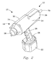
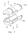
先ず、図1および図2を参照する。図1は、ガンアセンブリ12の主要構成要素の分解図であり、図2は、動作状態に組み立てたガンアセンブリ12の等角図である。
First, FIG. 1 and FIG. 2 will be referred to. FIG. 1 is an exploded view of the major components of the
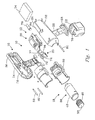
ガンアセンブリ12は、ハウジング部16、検知部18、回路部20(以下、「回路ボード部」20と呼ぶ)、電源22およびトリガ・アセンブリ23を備える。これらの構成要素(18〜23)は、ガン・ハウジング16に(あるいはその内部に)取り付けられる。
The
ガン・ハウジング16は、全体として、概ね細長い円筒形状を有する上部ハウジング部24とハンドル部26とを備える。ハンドル部26は、ガンアセンブリ12が全体としてピストルの形状を有するように上部ハウジング部24に連結される。そのため、上部ハウジング部24が水平に位置合わせされた状態で、ハンドル部26の上端部分が上部ハウジング部24の中央部に連結される。このハンドル部は、下向きかつ後向きに適度に傾いて上部ハウジング部24から下向きに延びる。本明細書では、ハンドル部26をしばしば、「ピストルグリップ」または「ハンドグリップ」と称する。検査ガンアセンブリ12は、扱いやすいように、軽量で釣り合いがよくとれている。ピストルグリップ26の下端には取付け構造部28があり、それによって電源22がガンアセンブリ12に取り付けられる。電源22は、電気的に、またはバッテリで電力を供給し得る。本発明が手動モードで用いられるように構成される場合、電源22は12ボルトのバッテリとすることが好ましい。
The
様々なコンポーネントの向きおよび相対的な位置を説明するために、上部ハウジング部24が、水平に位置合わせされるとみなし、かつ水平位置合わせ軸を有し、上部ハウジング部24の前端が位置合わせ軸の一端にあり、上部ハウジング部24の後端が位置合わせ軸の他端にあるようにガンアセンブリ12が配置されるとみなす。そのため、「前の」、「後の」、「上の」、「下の」、「横の」という用語、またはこれらに対応する他の用語は、ガンアセンブリ12が、そのハウジング部分を水平に位置合わせした状態で配置されると仮定した場合の「水平」という用語を基準にする。当然のことながら、様々な動作モードでは、ガンアセンブリ12は、「水平に位置合わせされる」以外の異なる姿勢をとり得ることが理解されよう。
To illustrate the orientation and relative position of the various components, the
また、「前壁」という用語は、この検査装置が、容器内に超音波パルスを送信するために最初に位置決めまたは配置される壁の部分、パネルその他の表面位置を意味すると解釈し、「後壁」という用語は、前壁から飛来した超音波パルスが前壁に向かって反射する位置に存在する第2の壁の部分、パネルまたは表面であると解釈するものとする。そのため、「前壁」および「後壁」は、慣習上容器の「前または後」とみなし得る容器上の位置を必ずしも意味しないものとする。 The term “front wall” is also taken to mean the part of the wall, panel or other surface location where the inspection device is initially positioned or placed to transmit an ultrasonic pulse into the container, The term “wall” shall be construed to be the second wall portion, panel or surface present at a location where the ultrasonic pulses coming from the front wall reflect towards the front wall. Thus, “front wall” and “rear wall” do not necessarily mean positions on a container that can conventionally be considered “front or rear” of the container.
ハウジング部16は、垂直に位置合わせされ長手方向に延びる中心面に沿って分離される2つの部分30および32から構成されていることが理解されよう。上部ハウジング部24は、前方ハウジング部分34および後方ハウジング部分36を有するとみなし得る。検知部18は、前方ハウジング部分34内に配置され、回路ボード部20は、後方ハウジング部分36内に配置される。
It will be appreciated that the
本発明の装置10は、密封した容器或いは密封していない容器、フローシステムおよびプロセス制御システム、出荷用コンテナ、貨物倉、およびバルク物質のキャリアなどや、それらの内部に収容される物質など、様々な容器を非侵襲かつ非侵入で検査するのに使用されるように特に適合される。本発明の1つの実用的な応用例は、液体が充填された容器を試験することである。そのため、以下の説明の大部分では、この装置が液体充填容器を検査する際に使用されるという想定で、本発明の動作を説明する。液体充填容器としては、比較的小型の容器(例えば、55ガロン(209リットル)のドラム缶やさらに小型の容器)や、液体物質を収容する大型タンク構造などの比較的大型の容器などがある。大型タンク構造は、例えば、タンクトレーラやタンクローラ上で搬送されるものであり、この構造は、直径8フィート(2.4m)または9フィート(2.7m)になることがある。より広い範囲では、本発明は、液体物質の容器の検査または調査だけに限定されるものではなく、例えば、バルクソリッド(bulk solid)の形態の商品やバルクソリッドが充填された容器など、非液体物質の容器の検査または取調べに使用し得ることが当業者には理解されよう。
The
次に、本発明の方法を簡潔に説明する。先ず、使用者は、検査すべき容器に対してガンアセンブリ12を位置決めすることによって、容器の検査を開始する。この位置決めは、検査中の容器の表面に、検知部18のトランスデューサ40の前側端部表面38を当てることによって行う。トリガ・アセンブリ23のトリガを強く握ることにより、検査装置を作動状態にして、超音波パルスを容器の壁から容器の収容チャンバ内に送信する。(以下の文章では、「パルス」という用語は、単一のパルスの他、一連のパルスからなる「バースト」や、正弦波の一部分などを含むと解釈すべきである。)
Next, the method of the present invention will be briefly described. First, the user initiates inspection of the container by positioning the
ガンアセンブリ12内のトランスデューサ40の前面38から放出される超音波パルスは、検査中の容器内の物質を貫通して伝播する。この超音波パルスが容器の遠い方の壁に達すると、音響エコーとして反射し送信位置に戻る。この音響エコーはトランスデューサ40に達し、トランスデューサ40は、この音響エコーを受信し、この音響エコーをアナログ電気信号に変換する。次いで、このアナログ信号は、さらなる処理を行うために回路ボード部20に送信されて、デジタル信号に変換される。その後、このデジタル信号は、回路ボード部20からコンピュータ(例えば、PDA、ラップトップ、デスクトップその他のコンピュータ)14に送信され、そこで、様々な処理が実施される。コンピュータ14の主な機能は、デジタル波形から得られた情報を、コンピュータ14のデータベース内に保持される様々な基準データと比較して、受信波形の情報が、容器内に存在すると想定される特定の物質に対応する基準波形の情報と一致するかどうかを確かめることである。
Ultrasonic pulses emitted from the
この好ましい実施形態では、コンピュータ14は、パルスの送信からエコーの受信までの時間差(「デルタ時間」とも呼ぶ)を解析し、この時間差を、超音波パルスの移動距離と超音波パルスが移動する物質の温度とに関連付ける。本発明のより広い範囲では、振幅、位相シフト、周波数、波形の各態様間の関係、またはこれらの組合せなどを含めて、波形の他の特徴を解析し、基準波形と比較する。波形の態様とは、所与の波形の固有なフィンガープリント(fingerprint)を表すものである。
In this preferred embodiment, the
コンピュータ14は、受信波形(およびその特徴)と、様々な物質に対応する基準情報データベースとの間で正しく一致するものを探す。一致するものが見つかった場合、該当する情報を表示または他の方法で使用者に伝えて、適切な処置をとることができる。例えば、国境検査の応用例で、検査官による音響エコーの解析により、容器または検知された内容物について不適切な何かが存在する可能性があることが示される場合、検査官はその容器を押収することができる。あるいは、一致するものが生じない(すなわち、検査/取調べにより陰性と判明した)場合、検査官は、容器が検査に合格したと認めることができる。本発明のより広い範囲では、このデータベースによる突合わせプロセスは、フローシステム(例えば、パイプ、配管、通気部など)またはプロセス制御ステーションにおける物質のオンライン若しくはリアルタイム監視による検査や、或いは密封した容器の内部または外部にあるバルクリキッド(bulk liquids)や固体の形態の商品の検査に、同じように良好に適用される。
The
上述したように、物質中の音速は温度の関数として変化することになるので、温度を考慮に入れなければならない。例えば、水中の音速は温度が高くなると増加し、ガソリン中の音速は温度が高くなると減少し得る。 As mentioned above, the speed of sound in a substance will change as a function of temperature, so the temperature must be taken into account. For example, the speed of sound in water can increase as the temperature increases, and the speed of sound in gasoline can decrease as the temperature increases.
さらに、ある種の適用例では、容器内の比較的大型のバルク物質内に隠蔽された問題の物体が存在し得る。例えば、密輸品の梱包物が、バルクリキッドまたは乾燥した固体の商品などの内部に隠されて置かれていることがある。この例では、超音波パルスは、バルク含有物質内の物体の界面に到達する。この物体はバルク物質と異なるので、物体と物質の界面で音響エコーが生じることになる。この初期音響エコーは、容器の遠い方の壁からの第1の主音響エコーがトランスデューサ40に到達する時間よりも前に、トランスデューサ40に到達することになり、それによって、この問題の物体を確認し特定することができる。
Further, in certain applications, there may be a problem object concealed within a relatively large bulk material in the container. For example, a smuggled package may be hidden inside a bulk liquid or a dry solid product. In this example, the ultrasonic pulse reaches the interface of the object in the bulk-containing material. Since this object is different from the bulk material, an acoustic echo is generated at the interface between the object and the material. This initial acoustic echo will reach the
次に、この装置の様々なコンポーネントおよび本発明の方法のより具体的な説明を示す。 The following is a more specific description of the various components of the apparatus and the method of the present invention.
b)検知部18
第1低周波トランスデューサ40および第2高周波トランスデューサ40の2つのトランスデューサ40をガンアセンブリ12と組み合わせて使用する。低周波トランスデューサ40は200kHzで動作し、高周波トランスデューサ40は1MHzで動作する。一般に、低周波超音波パルスは、高周波超音波パルスよりも遠くに伝播し得る。したがって、他の減衰要因を考慮に入れなければならない場合を除いて、低周波トランスデューサ40は通常、比較的大型の容器(すなわち、トレーラ上の8フィート(2.4m)×9フィート(2.7m)の径のタンク)の取調べまたは調査に使用され、高周波トランスデューサ40は、比較的小型の容器(すなわち、バルクリキッドを収容する55ガロン(209リットル)のドラム缶)に使用される。上記で選択した特定の周波数は、全体として最良の有利な選択であることがわかっているが、明らかに、2つ以上のトランスデューサを選択して、様々な調査適用例に対処することができるはずである。例えば、周波数の選択は、試験する容器の寸法、容器内の物質のタイプ、温度その他の周囲環境条件、物質のレオロジー的かつ音響学的な特性を含めていくつかの要因、並びに他の要因によって決まるが、上記の要因の例に限定されるものではない。そのため、選択する周波数は、必要性または適用例に応じて変化し得る。
b)
Two
(低周波または高周波の)トランスデューサ40はそれぞれ、従来より市販されている構造のものを用いることが可能であるが、検査装置に適合するように一部を変える必要がある。例えば、低周波トランスデューサ40は、市販品の場合、高周波トランスデューサ40よりもいくらか径が大きい。そのため、低周波トランスデューサ40のケーシングの、ハウジングの外側の余分な材料の一部を機械加工して落とし、それによって高周波トランスデューサ40と同じ(あるいはそれとほぼ一致する)外部構造とする。
Each of the transducers 40 (low frequency or high frequency) can have a structure that has been commercially available in the past, but it is necessary to change a part of the
前述したように、トランスデューサ40は前端接触表面38を有し、それを試験または取調べ中の容器の壁に位置決めし押し付ける。トランスデューサ40は、いくつかの独特な特徴を有する。この実施形態では、例えば、トランスデューサ40の前端接触表面38は部分的に、この表面に付着させた独特な乾燥結合膜(dry-coupling membrane)を備える。この膜は、音響ゲル(acoustic gels)その他の結合剤を必要とせずに、容器の表面を貫通して音響送信を結合させる。このように、トランスデューサ40は、いかなる接触ゲル(「音響ゲル」)も実質的に不要になるように設計される。このゲルは一般に、物質中に音響エネルギーを効率的に送る(カップリングする)ために従来技術で使用されるものである。
As previously described, the
次に、図3を参照する。この図は、トランスデューサ40の前端部分38を、ガンアセンブリ12の長手方向中心線に一致する面に沿って切断した断面図である。円形形状のディスクの形態をとる合成ゴムまたはゴムの層42が設けられ、それによって、トランスデューサ40の前面44全体が覆われる。好ましい実施形態では、この層42はネオプレン(neoprene)層である。層42は、この実施形態では薄いウレタン層46である接着層46によって、トランスデューサ40の前面44に結合される。ネオプレン層42を貼りつける方法は以下の通りである。先ず、ネオプレン層42の裏面と、トランスデューサ40の前面44に液体ウレタンを塗布する。(なお、これら2つの表面の一方だけに先ず、ウレタン層を塗布することが適切な場合もある。)次いで、ネオプレン層42を、トランスデューサ40の前面44の定位置に置き、ウレタン層46に押し付ける。その後、ネオプレン層42に圧力プレートを重ね、ネオプレン層42に押し付ける。クランプ(例えば、C形クランプ)、または他の何らかの類似の装置によってこのプレートを定位置に保持する。次いで、この圧力プレートをネオプレンの表面38にクランプした状態のまま、トランスデューサ40を真空(すなわち、低圧環境)中に約15〜20分間置いて、半液体ウレタン層から閉じ込められている空気を逃がす。その後、真空環境からトランスデューサ40を取り出し、周囲の条件および気圧で24〜48時間、あるいは、シールが完全かつ適切に硬化するまで硬化させる。そして、硬化・固化後に、ネオプレン層の下から押し出された余分なウレタンをトランスデューサから切り落とす。
Reference is now made to FIG. This view is a cross-sectional view of the
現在の構成で選択されるネオプレン層42は、高周波トランスデューサでは厚さ約0.0625インチ(1.59mm)であり、低周波トランスデューサでは厚さ約0.1875(4.76mm)インチである。
The
ネオプレン層42の厚さは、意図する適用例に応じて変えることができる。例えば、薄いほうでは、ネオプレン層42は、0.06、0.05、0.04インチ(1.52、1.27、1.02mm)まで、おそらくはさらに0.03インチ(0.76mm)まで薄くし得るはずである。さらに、ネオプレン層42は、0.8〜0.16インチ(20.3〜4.06mm)の間を0.01インチ(0.25mm)刻みで厚くした寸法のいずれか1つ、あるいは、厚さ0.16インチ(4.06mm)よりも厚いほうでは、0.01インチ(0.25mm)刻みで0.2、0.3、または0.4インチ(5.08、7.62、または10.2mm)にも厚くした寸法のいずれか1つとし得るはずである。厚さの選択は、様々な処理条件によって決まることになるが、試験する容器の表面の構造に応じて変化することにもなる。また、接触する容器の表面に凹凸またはリバースカーブ(reverse curves)がある場合、これらの表面構造により良好にならうように厚さを変更し得るはずである。
The thickness of the
本発明に適したネオプレンは、低音響インピーダンスおよび以下の特徴を有するべきである。 Neoprene suitable for the present invention should have low acoustic impedance and the following characteristics.
本発明の好ましい実施形態で使用する市販グレードのネオプレンゴム材料に重要な乾燥結合特性は、1)材料の硬さが40A Durameter(例えば、「軟らかい」)であり、2)音響インピーダンスが2.1gm・cm-2・sec-1×10⁵、3)長手方向の音速が0.063インチ(1.6mm)/マイクロ秒、4)密度が1.31gm・cm-3であることを含む。 Important dry bonding properties for commercial grade neoprene rubber materials used in preferred embodiments of the present invention are: 1) material hardness of 40A Durometer (eg, “soft”) and 2) acoustic impedance of 2.1 gm. -Cm -2 · sec -1 × 10 5 , 3) including that the longitudinal sound velocity is 0.063 inch (1.6 mm) / microsecond, and 4) the density is 1.31 gm · cm -3 .
これらのパラメータを変えることができるはずであることは明らかであり、例えば、以下のように変えることができよう。 Obviously, these parameters should be changeable, for example, as follows:
材料の硬さは、低い方では、40A(「軟らかい」)等級から、50A(「中程度」)等級を経て、高い方では70A(「硬い」)等級までの範囲とし得る。 The hardness of the material can range from the 40A ("soft") grade on the lower to the 50A ("moderate") grade and the 70A ("hard") grade on the higher.
音響インピーダンスはおそらくは、低い方では、1.0、1.5、または1.8gm・cm-2・sec-1×10⁵から、高い方では、2.5、3.0、3.5、または4.0gm・cm-2・sec-1×10⁵の値までの範囲とし得る。 The acoustic impedance is probably from 1.0, 1.5, or 1.8 gm · cm −2 · sec −1 × 10 5 on the lower side, 2.5, 3.0, 3.5, Alternatively, the range may be up to a value of 4.0 gm · cm −2 · sec −1 × 10 5 .
長手方向の音速は、低い方では、0.05インチ(1.27mm)/マイクロ秒から、高い方では、0.065、0.07、0.075、0.08、または0.085インチ(1.65、1.78、1.91、2.03、または2.16mm)/マイクロ秒の値までの範囲とし得る。 Longitudinal sound speeds range from 0.05 inches (1.27 mm) / microseconds on the lower to 0.065, 0.07, 0.075, 0.08, or 0.085 inches (higher). 1.65, 1.78, 1.91, 2.03, or 2.16 mm) / microsecond values.
密度(gm・cm-3)は、低い方では、0.9、1.0、1.1、または1.2から、高い方では、1.35、1.5、2.0、2.5、3.0、または3.5の範囲とし得る。 The density (gm · cm −3 ) is from 0.9, 1.0, 1.1, or 1.2 at the lower side and 1.35, 1.5, 2.0, 2. It can be in the range of 5, 3.0, or 3.5.
ネオプレンは、結合膜または結合層の材料42として極めて満足のいくものであることがわかっているが、層42には他の材料を使用し得るはずである。このような材料の候補の中には、ソリッドウォータ(solid water)その他の水性静菌性隔離材料(aqueous bacteriostatic standoff material)、例えば、Aquaflex(登録商標)(米国ニュージャージー州07004 Fairfield所在のParker Laboratories社)、シリコーンゴム、RTV(Room Temperature Vulcanizing)シリコーンゴム、ブチルゴム、ウレタン、ポリウレタン、熱可塑性ウレタン、Ecothane(登録商標)およびPellathane(登録商標)(米国デラウェア州19804 Wilmington所在のOptimer社)などがある。
Neoprene has been found to be very satisfactory as the
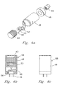
検知部18の他のコンポーネントを説明するために、次に図1、図4a〜図4d、図5、図6および図7を参照する。トランスデューサ40は、概ね円筒形の保持ケース48の前方部分に配置される。この実施形態ではサーミスタ49である温度センサ49を、トランスデューサ40の側壁に隣接して配置し、かつトランスデューサ側壁のスロット内に位置決めし得るはずである。また、ケーブル52によって電気コネクタ54に接続されるソケット部材50をケース48内に位置決めする。また、保持ケース48の後端には、環状構造を有し、コネクタ54と係合する後部保持部材56が配置される。
In order to describe other components of the
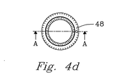
トランスデューサ40、ソケット50、ケーブル52、コネクタ54、保持部材56、温度センサ49および保持ケース48は、1つのユニットとして機能する。このユニットは、上部ハウジング部24の前方端部34内に取り付けられる。これらのコンポーネント40、48〜49および50〜56は、総称して「トランスデューサ・アセンブリ58」または「トランスデューサ・ユニット58」と称する。図4aに、トランスデューサ・アセンブリ58を、コンポーネントに分解した図で示す。図4bに、トランスデューサ・アセンブリ58を、トランスデューサ・アセンブリ58の中心軸を通って延びる長手方向の面に沿って切断した断面で示す。図4cに、トランスデューサ・アセンブリ58を側面図で示し、図4dに、トランスデューサ・アセンブリ58を上面図で示す。
The
次に、図1、図5a、図5b、図5c、図6および図7を参照する。これらの図に、センサ収容アセンブリ60を示す。センサ収容アセンブリ60内には、トランスデューサ・アセンブリ・ユニット58が、ばね荷重により前後の動きが制限された状態で取り付けられ、かつ前方位置に付勢される。このセンサ収容アセンブリ60は、長手方向水平中心面に沿って互いに分離する2つのパーツ62aおよび62bからなるセンサ収容ハウジング62(図6および図7参照)を備える。センサ収容ハウジング62は、概ね円筒形の形状を有し、2つの半分のパーツ62aおよび62bは、適切な留め具(例えば、ねじ)その他の手段によって互いに固定される。
Reference is now made to FIGS. 1, 5a, 5b, 5c, 6 and 7. FIG. In these figures, the
次に、図5a、図5bおよび図5cを参照する。これらの図には、センサ収容アセンブリ60の一部を示す。端部取付片64が、センサ収容ハウジング62の後側に取り付けられ、電気コネクタ66の後端が端部取付片64に取り付けられる。圧縮コイルばね68が、端部取付片64にあてがわれるようにセンサ収容ハウジング60の後方部分に取り付けられ、それによって、トランスデューサ・アセンブリ58が押し付けられ、前方位置に向かって付勢される。トランスデューサ・アセンブリ58とセンサ収容ハウジング62の間に、前後の動きの案内として、またこの前後の動きを制限するために適当なトング−スロット相互接続部(tongue-and-slot interconnection)が設けられる。
Reference is now made to FIGS. 5a, 5b and 5c. In these figures, a portion of the
トリガ・アセンブリ23(図1)は、旋回位置74の周りに旋回可能に取り付けられたトリガ部材72(またはトリガ72)、トリガ部材72を前方に付勢するようにトリガ部材72の背後に位置決めされたばね部材76、およびトリガ72の後方で回路ボード部20に接続されるトリガスイッチ77を備える。
The trigger assembly 23 (FIG. 1) is positioned behind the trigger member 72 to bias the trigger member 72 forward, the trigger member 72 (or trigger 72) mounted pivotably about a
さらに図1を参照すると、電源22が、その上面に適切な取付けコンポーネント78を有することがわかる。取付けコンポーネント78は、ピストルグリップ26の下端の電源取付け部分28の突合わせコンポーネントにはめ込まれる。例えば、この接続部は、スライド式接続部の形態を取り得るはずである。バッテリ(すなわち、電源)22をピストルグリップ26の下端の後方に位置決めし、前方に移動させて、ピストルグリップ26の下側接続部分とスライド式に係合させる。
Still referring to FIG. 1, it can be seen that the
図1には、ケーブル(図示省略)によって回路ボード部20をコンピュータ14に接続して、コンピュータ14と情報をやり取りするケーブル接続部79も示す。本発明の一実施形態では、ケーブル接続部79は、回路ボード部20をPDA14に接続する。
FIG. 1 also shows a
本発明の別の実施形態では、ケーブル接続部79は、回路ボード部20をデスクトップ・コンピュータ14に接続する。あるいは、回路ボード20からの出力信号は、無線周波その他の搬送波技術(例えば、赤外線、マイクロ波)によってコンピュータ14に送信し得るはずである。
In another embodiment of the invention, the
図1には、上部ハウジング部24の前端から前方に延びる三角形状に配置された3つのスタンドオフ(standoff)82も示す。使用者は、これらを使用して、装置12を、それに隣接する容器表面に対して適切な向きに位置決めし得る。本出願人が企図している現在の設計には、これらのスタンドオフ82が組み込まれていない。しかしながら、ある種の適用例では、これらのスタンドオフ82は、超音波センサと表面の結合を改善するのに、この表面が平坦か平坦でないか、あるいは起伏があるかどうかにかかわらず、有利になり得るはずである。
FIG. 1 also shows three
図1で、ガン・ハウジング16の上面後方部分は、平坦な表面部分84(すなわち、台84)を有することに留意されたい。この表面部分84は、この平坦な表面すなわち台の上にPDA14を配置し、適当な方法(例えば、Velcro(登録商標)その他の何らかの留め具または装置)で固定し得るように設けられる。そのため、操作者は、検査装置のガンアセンブリ12を操作するのと同時に、PDA14の表示パネルを見ることができるはずであり、各種の測定値および情報を表示したり、或いはコマンドをPDA14に入力し得るはずである。若しくは、ガンアセンブリ12を遠隔的に、すなわち、表示コンピュータ14から離れたところで操作し得るはずであり、それによって、測定値、データおよび情報を読み出し、また、プロセス監視ステーションまたは類似のフローシステム・アプリケーションから、無線周波数、超音波や赤外線の信号その他の信号化手段を介してユーザコマンドを入力し得るはずである。
It should be noted in FIG. 1 that the upper rear portion of the
これらのコンポーネントの組み立て方は、図1の分解図を見れば容易に理解し得ると思われる。 The assembly of these components can be easily understood by looking at the exploded view of FIG.
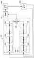
c)回路部(すなわち、回路ボード部)20
回路ボード部20は、4つの個々の回路ボード・コンポーネント、すなわち、
i.パルス発生ボード800
ii.受信ボード900
iii.信号処理・制御ボード(以下、「デジタルボード」と呼ぶ)1000
iv.通信インターフェースボード(以下、「PicoWeb(商標)ボード」と呼ぶ)1100
を備える。
c) Circuit portion (ie, circuit board portion) 20
The
i.
ii.
iii. Signal processing / control board (hereinafter referred to as “digital board”) 1000
iv. Communication interface board (hereinafter referred to as “PicoWeb (trademark) board”) 1100
Is provided.
これらをそれぞれ簡潔に説明し、その後で、より詳細な説明を行う。 Each of these will be briefly described, followed by a more detailed description.
図8に示すように、パルス発生ボード800は、HF(高周波)パルスまたはLF(低周波)パルスのいずれかを、容器の検査を行う検知部18に伝送する高周波回路部分820および低周波回路部分830を有する。ガンアセンブリ12に(高周波または低周波の)いずれのトランスデューサ・アセンブリ58を配置するかに応じて、デジタルボード1000を介して、HF(高周波)回路部820またはLF(低周波)回路部830のいずれかに同期信号を送信して、適切な回路を準備が整った状態にする。次いで、パルス発生ボード800が、トランスデューサ40に信号を送信して、HF回路820またはLF回路830における(高周波または低周波)超音波パルスの出力を開始する。サンプル容器を検査するためにHF回路820またはLF回路830のいずれかで生成された信号は、パルス発生ボード800上のリレー回路要素840によって検知部18に送られる。そして、この信号は、受信ボード900に受信された後、さらなる処理を行うために、デジタルボード1000に送信または伝達される。
As shown in FIG. 8, the
トランスデューサ40が、検査の結果生じた1つまたは複数の音響エコーを受信した後で、受信ボード900(図9参照)は、(この時点で装置内で使用されているトランスデューサに応じて)高周波または低周波のトランスデューサ40からの戻りアナログ信号を受信して、この信号を増幅した後、このアナログ信号をデジタルボード1000(図10)に送信する。
After the
信号処理・制御ボード1000(図10;以下、「デジタルボード」1000と呼ぶ)は、受信ボード900からアナログ信号を受信し、このアナログ信号をデジタル信号に変換し、次いで、このデジタル信号をインターフェースボード1100を介してコンピュータ14に送信するという主要機能を含めて、いくつかの機能を実施する。デジタルボード1000は、いくつかの他の機能を有するが、これらは、本明細書で後でより詳細に説明することになる。
The signal processing / control board 1000 (FIG. 10; hereinafter referred to as “digital board” 1000) receives an analog signal from the receiving
インターフェースボード1100は、デジタルボード1000とコンピュータ14の間の通信リンクとして機能し、デジタルボード1000からの情報を、コンピュータ14が容易に受信し得るフォーマットで送り出す。インターフェースボード1100は、コンピュータ14とデジタルボード1000の通信リンクとしても働き、それによって、コンピュータ14とデジタルボード1000の間で情報のやり取りが行われる。
The
インターフェースボード1100は、従来型若しくは市販のタイプのものとし得る。好ましい実施形態では、このインターフェースボードは、現時点ではPicoWeb(商標;以下省略)サーバ用イーサネット通信ボード(米国カリフォルニア州92037−3044 La Jolla所在のLightner Engineering社)である。
The
ここで、これら4枚のボードをより詳細に説明する。 Here, these four boards will be described in more detail.
i.パルス発生ボード800
図8のブロック図を参照する。図8で、パルス発生ボード800の回路をより詳細に示し説明する。
i.
Reference is made to the block diagram of FIG. FIG. 8 shows and describes the circuit of the
パルス発生ボード800への初期入力は、操作者(すなわち利用者)が、トリガ・スイッチ77を作動させるためにトリガ72を強く握る動作によりスイッチ・アセンブリ23が作動されるときに、デジタルボード1000(図10)を介してトリガ信号すなわち同期信号として入来する。
The initial input to the
図8に示すように、2つのパルス発生部、すなわち、(経路要素822〜826を備える)高周波パルス発生部820および(経路要素832〜836を備える)低周波パルス発生部830が設けられている。その信号は、ガンアセンブリ12内に高周波または低周波のトランスデューサ40のいずれを取り付けるかに応じて、高周波「作動」信号822または低周波「作動」信号832のいずれかになる。この初期信号は、それが高周波信号822である場合には、高周波パルス発生部820に送られ、そこを通過する。この初期信号は、それが低周波信号832である場合には、低周波パルス発生部830に送られ、そこを通過する。
As shown in FIG. 8, two pulse generators are provided: a high-frequency pulse generator 820 (comprising path elements 822-826) and a low-frequency pulse generator 830 (comprising path elements 832-836). . The signal is either a high frequency “activate” signal 822 or a low frequency “activate” signal 832 depending on whether a high frequency or
デジタルボード1000から高周波作動信号822を受信すると、それは駆動増幅器回路824に送られる。次いで、駆動増幅器824は、高周波パルス電源826内の高電圧スイッチにゲート信号を送信して、高電圧パルスが出力される。この高電圧パルス出力は、この出力を受信するように設定されたリレー840に送られ、次いでこの信号は、検知部18に送信される。好ましい形態では、高周波パルス発生部820から検知部18に送信される信号は、385ボルトの方形波パルスであり、それによって高周波トランスデューサ40が、サンプル容器の検査を行うための高周波超音波パルスの出力を開始する。この高電圧パルス出力信号は、検知部18に送信される。戻りエコーは、検知部18から受信された後、受信ボード900を介してデジタルボード1000に送信されてデジタル化が行われる。その後、デジタル化された信号は、PicoWebインターフェースボード1100を介してホストコンピュータ14に通信される。
Upon receipt of the high
低周波作動信号832が初期同期信号あるいはトリガ信号として受信されるとき(これは、ガンアセンブリ内に低周波トランスデューサ部が取り付けられるときに生じることになる)、実質的に同じシーケンスが行われる。この構成では、低周波開始信号832が、これに対応する増幅器834に低周波入力として送られ、次いでその出力が、低周波パルス電源836に入り、低周波パルス電源836によりバーストパルスが生成される。好ましい実施形態では、このバーストパルスは、それぞれ約600ボルトの電圧を有する数サイクル〜多数サイクルの正弦波形バーストまたはトーンバースト(tone burst)を含む。リレー840は、低周波パルス電源の出力信号を受け取り、この信号を検知部18に送信する。次いで、このパルス信号は、作動時にガンアセンブリ12内に取り付けられている低周波トランスデューサ40を作動させる。高周波パルスの場合と同様に、この低周波信号は、受信ボード900に送信され、デジタルボード1000によってデジタル化され、PicoWebインターフェースボード1100を介してコンピュータ14に通信される。
When the low
本発明のより広い範囲では、本発明のこの実施形態に関して本明細書で論じた動作パラメータは、応用例に応じて変わり得ることが当業者には容易に理解されよう。 It will be readily appreciated by those skilled in the art that, within the broader scope of the present invention, the operating parameters discussed herein with respect to this embodiment of the present invention may vary depending on the application.
例えば、高周波パルス822の電圧は、400、450、500、600、700、800、900、またはおそらくは1,000ボルトという高い電圧レベルになることもあり、あるいはおそらくは、350、300、250、200、または150ボルト、あるいはそれ以下という低い電圧レベルにもなり得る。同様に、低周波バーストの様々なパラメータも変化し得る。例えば、この低周波バースト832の電圧は、低い方では、200、300、400、500ボルトにも低くなることがあり、あるいは高い方では、700、800、900、1,000ボルト、またはそれ以上にも高くなり得る。
For example, the voltage of the
ii.受信回路ボード900
次に、図9を参照する。図9には、受信ボード900のブロック図を示す。パルス発生ボード800からのパルスがトランスデューサ40に送信されて、検査中の容器を取り調べる低周波または高周波の超音波パルスが生成された後で、1つまたは複数の戻り音響エコーが、トランスデューサ40によって受信され、アナログ信号に変換される。このアナログ信号は、受信ボード900によって受信され、アナログ信号としてデジタルボード1000(図10)に送られる。このアナログ信号のデジタル化は、デジタルボード1000上にあるアナログ/デジタル・コンバータ1020によって行われる。
ii.
Reference is now made to FIG. FIG. 9 shows a block diagram of the receiving
図9では、受信回路ボード900への入力信号は、検知部18から受け取り、電圧リミッタ920に送られる。電圧リミッタ920は、高振幅送信パルスから受信ボード900を保護するが、(1ボルト未満の)低振幅エコーを通過させることができる。上述したように、戻り信号は、1つまたは複数の音響エコーが戻る結果生じる1つまたは複数の信号成分を含み得る。
In FIG. 9, an input signal to the
電圧リミッタ920を介して受信した戻り信号910は前置増幅器930に送られ、前置増幅器930からの増幅信号出力は、100kHz以上の周波数を通過させるハイパスフィルタ940に送られ、そこを通過する。次いで、ハイパスフィルタ940からの信号出力は、可変利得増幅器950に送られ、その後、後置利得増幅器960を介してデジタルボード1000に至る。
The return signal 910 received via the
この受信回路900内の可変利得増幅器950は、デジタルボード1000の制御下にあり、この検査装置の利用者/操作者は、コマンドを入力して可変利得増幅器950を調整することによって受信信号910を増幅させることができる。
The
後置利得増幅器960としては、従来型のものを用いることが可能である。その一実施形態として、2段階式の後置利得増幅器960がある。この後置利得増幅器960では、第1段で信号強度を20dB増加させ、第2段で信号強度をさらに20dB増加させる。
As the
受信ボード900からの出力は、増幅されたアナログ信号であり、このアナログ信号は、デジタルボード1000に送られて、アナログ/デジタル・コンバータ1020(図10)によりデジタル信号に変換される。
The output from the
iii.デジタルボード1000
次に、図10を参照する。図10には、デジタルボード1000のブロック図を示す。図10のブロック図に示す各コンポーネントの全体的な機能を説明し、次いで、デジタルボード1000の全体的な動作を検討する。
iii.
Reference is now made to FIG. FIG. 10 shows a block diagram of the
デジタルボード1000上では、電力レギュレータ(DC−DCコンバータ)1005が、電源(例えば、バッテリその他の電源)22から+12ボルトの電力入力を受け取る。この単一入力電源電圧から、電力レギュレータ1005は、回路部20内および検査装置10内の様々な構成要素の要件に基づいて複数の出力電圧を提供する。より具体的には、レギュレータ/コンバータ回路1005は、+12ボルトの電力入力源電圧を、+10ボルト出力の第1電圧、+5ボルト出力の第2および第3の電圧、並びに+3.3ボルト出力の第4および第5の電圧の5つの電圧出力に変換する。
On the
第1の場合、レギュレータ1005は、電源22から受け取った+12ボルトの入力源電圧を、パルス発生ボード800、受信ボード900およびデジタルボード上の主要回路を駆動する+10ボルト出力に変換する。より具体的には、レギュレータ1005からの+10ボルト出力電圧により、パルス発生ボード800上に配置されたHFパルス発生回路820およびLFパルス発生回路830、並びに受信ボード900上の各コンポーネントがイネーブルになり、かつそれらに電力が供給される。受信ボード900上では、デジタルボードインターフェース1015を介して、前置増幅器930、ハイパスフィルタ940、可変利得増幅器950、および後置利得増幅器960など、個々のコンポーネントにそれぞれ+10ボルト出力が供給される。好ましい構成では、レギュレータ1005からの+10ボルト出力により、D/Aコンバータ1050およびデジタルインターフェース回路(パルス発生/受信ボードインターフェース)1015にも電力が供給される。後者のコンポーネントにより、パルス発生ボード800と、受信ボード900と、デジタルボード1000との間でデータおよび情報を転送する極めて重要なインターフェースが提供される。
In the first case, the
コンバータ1005はさらに、2つの+5ボルト出力電圧を提供する。第1の+5ボルト出力(例えば、+5V_HV)は、パルス発生ボード800上の高周波パルス発生部820に入力として提供され、そこで385ボルトの方形波高電圧出力になる。
より具体的には、この電圧は、デジタルボードインターフェース1015を介して、パルス発生ボード800に供給され、そこで、高周波パルス電源回路826に入力される。コンバータ1005からの第2の+5ボルト出力(例えば、+5V_PICO)は、デジタルボード1000上のPicoWebインターフェース論理回路1010に供給される。コンバータ1005はさらに、2つの+3.3ボルト出力を提供する。第1の+3.3ボルト出力(例えば、+VA)は、デジタルボード1000上のA/Dコンバータ1020など、様々なアナログ回路に送達され、それらに電力を供給する。第2の+3.3ボルト出力(例えば、+VD)は、FPGAコンポーネント1025、マイクロプロセッサ1030、FIFOコンポーネント1040、温度センサ用A/Dコンバータ1045、EEPROM回路部1055およびRAMコンポーネント1060など、デジタルボード1000の他の回路に送達され、それらに電力を供給する。
More specifically, this voltage is supplied to the
デジタルボード1000はさらに、回路部20とやり取りする信号や情報を受信し、処理し、かつ送信する主要な機能を果たすマイクロプロセッサ・コンポーネント1030(マイクロコントローラ)を備える。マイクロプロセッサ1030は、データ取得およびユーザインターフェース機能を制御する。
The
マイクロプロセッサ1030はさらに、様々な電力入力および信号入力を受け取り、それらを処理する。例えば、マイクロコントローラ1030とコンバータ1005は動作可能に接続される。コンバータ1005は、マイクロコントローラ1030からコンバータ1005に送信されるイネーブル信号(例えば、ANALOG_ON)によってオンオフ制御される。
デジタルボード1000のマイクロプロセッサ1030は、従来タイプのものとし得る。好ましい実施形態では、マイクロプロセッサ1030は、現時点では、Texas Instruments社(米国テキサス州75243−4136 ダラス所在)から市販されているMSP−430F OTP/EPROMチップである。
The
他の同等のコンポーネントが、このマイクロプロセッサに必要とされる機能を提供し得ることが当業者には理解されよう。そのため、本明細書で特定のコンポーネントを使用することによって、素子のタイプ、機能、または範囲を制限することを明示的または本質的に意味または示唆するものではない。 Those skilled in the art will appreciate that other equivalent components may provide the functionality required for this microprocessor. Therefore, there is no explicit or essential meaning or suggestion by the use of specific components herein to limit the type, function, or range of elements.
図10に示すように、マイクロプロセッサ1030は、電力レギュレータ1005、FPGA1025、FIFOメモリ回路1040、EEPROM回路1055、LED表示コネクタ1075およびテストスイッチコネクタ1090など、デジタルボード1000上の多数のコンポーネントに動作可能に接続され、それらとやり取りを行う。マイクロプロセッサ1030は、デジタルボードインターフェース1015によって、パルス発生ボード800および受信ボード900の様々なコンポーネントとも通信し、それらとやり取りを行う。
As shown in FIG. 10, the
マイクロプロセッサ1030はさらに、デジタルボード1000上にあるPicoWebインターフェース1010によって、PicoWebボードとやり取りを行う。PicoWebインターフェース1010は、PicoWebインターフェースコネクタ1085およびPicoWebパラレルI/Oコネクタ1110を介してPicoWebボードに動作可能に接続される。
The
マイクロプロセッサ1030は、8本のデータラインと14本のアドレスラインからなるバス要素を含み、これにより、マイクロプロセッサ1030はやり取りを行うことができ、これらのラインは、マイクロプロセッサ1030の動作制御下で様々なコンポーネント間でデータおよび情報を伝達する。
例えば、マイクロプロセッサ1030の主要な機能は、A/Dコンバータ1020から、デジタル変換された信号データを送信することである。さらに、図10に示すように、マイクロプロセッサ1030は、EEPROMメモリ回路1055、FIFOメモリ回路1040と信号データの送受信も行う。また、マイクロコントローラ1030は、パルス発生ボードコネクタ1015を介して、パルス発生ボード800の高電圧回路820にイネーブル信号(例えば、HV ON)を送信して、高電圧をオンにする。
For example, the main function of the
デジタルボード1000上のマイクロプロセッサ1030は、装置10に取り付けられたトランスデューサ40の(LFまたはHFのいずれかの)タイプを認識・判定することもできる。
The
マイクロプロセッサ1030は、パルス発生/受信ボードコネクタ1015を介して、装置10に取り付けられたトランスデューサ40の(LFまたはHFのいずれかの)タイプを示す信号(例えば、TYPE RLY)と、温度用A/Dコンバータ1045からのデジタル化された温度波形信号とを検出し受信する。マイクロプロセッサ1030は、受信ボード800から受信したセンサタイプに関する入力信号と、デジタルボード1000上の温度用A/D回路1045からの出力信号を処理する。
マイクロプロセッサ1030(図10)は、FPGA1025にイネーブル信号(例えば、FIRE)を送信する役割も果たす。このイネーブル信号は、この回路を初期化し、かつこの回路との同期を取り、その結果、HFパルス−トリガ/同期信号およびLFパルス−トリガ/同期信号が出力され、それぞれパルス発生ボード800のHF信号チャネル820またはLF信号チャネル830に送信される。この信号はさらに、FPGA1025に、その繰返しサイクルを開始するタイミングを知らせる。
The microprocessor 1030 (FIG. 10) also serves to send an enable signal (eg, FIRE) to the
マイクロプロセッサ1030は、シリアル通信回路1065を介してデバッグ用コネクタ1080と通信するようにも構成される。この回路(例えば、マイクロプロセッサ1030からデバッグ用コネクタ1080まで)は、マイクロプロセッサ1030や装置10のトラブルシューティングをうまく進めるために、プログラミング中でのみ使用される。
The
マイクロプロセッサ1030は、デジタルボード1000上のLED表示素子部1075ともやり取りを行って、LED表示素子部1075に信号(例えば、FIRE、ERRORなど)を送る。好ましい実施形態では、LED表示素子部1075は、先ず検査装置10に電力が供給されたときに点灯する第1のLED、検査装置10が作動状態になったことを示す信号(例えば、FIRE)を受信したとき、または波形データを取得したときに点灯する第2のLED、およびエラー信号(例えば、ERROR)が発生したときに点灯する第3のLEDの3つの独立したLEDを備える。
The
マイクロプロセッサ1030はさらに、操作者がトリガスイッチ1070を作動させたときに出力される検査装置10の検査(例えば、波形)信号データを受信し、処理し、送信する。
The
マイクロプロセッサ1030の他の重要な機能には、FIFOデータ・バッファ回路1040、EEPROMメモリ回路1055、並びにPicoWebインターフェース論理回路1010とのやり取り・通信が含まれる。
Other important functions of the
デジタルボード1000の別のコンポーネントであるFPGA(Field Programmable Gate Array)1025は、マイクロプロセッサ1030に動作可能に接続される。FPGA1025は、1)遅延時間、2)デジタル化速度、3)低周波トランスデューサ部58から放出されるバースト・サイクルの周波数、および4)高周波トランスデューサ部40の高周波パルス幅を制御するように機能する。さらに、FPGA1025には、その機能を実施するためにコードが物理的に組み込まれており、FPGA1025は、2つの仮想シリアルポート(通信インターリンク)を介してマイクロプロセッサ1030と通信・やり取りを行う。好ましい実施形態では、シリアル通信は、「2線式」すなわち「I2C」プロトコルを用いて実施される。この好ましい構成では、第1シリアル・インターリンク(例えば、SDA)は、マイクロプロセッサ1030からFPGA1025に、操作者が制御・構成するデータを送信する。第2シリアル・インターリンク(FPGA_SCL)は、この構成データをFPGA1025に移動させて、装置10がこれらのパラメータを利用できるようにする。このようにして、それぞれのHFパルス発生回路820およびLFパルス発生回路830の動作パラメータ(例えば、パルス幅、パルスの送信タイミングおよび周波数、パルスを送信する頻度、バースト中のパルス数など)を、FPGA1025に送信し、FPGA1025を介して検査装置10に通信する。
An FPGA (Field Programmable Gate Array) 1025 that is another component of the
FPGA1025は、プログラムを書き換えることができ、あるいは、プログラミングを改変して追加の機能を実施し得るという点で独特なものである。FPGA(すなわち、「ゲートアレイ」)1025のプログラミングの改変は、4本の追加の通信ライン(例えば、TDO_FPGA、TMS_FPGA、TDI_FPGA、およびTCK_FPGA)を備えるJTAGインターフェース要素(図示省略)を介して行われる。装置10の正常な動作中には、JTAGインターフェースは使用しない。
The
FPGAコンポーネント1025は、パルス発生ボード800のそれぞれのHF回路部820およびLF回路部830への入力として、LFトリガ/同期パルスおよびHFトリガ/同期パルス(例えば、それぞれPULSER_TRIG_LFおよびPULSER_TRIG_HF)の出力を開始する役割を果たす。FPGA1040は、パルス発生ボード・インターフェース・コネクタ1015に動作可能に接続され(図10参照)、それによってトリガパルスが、パルス発生制御回路800の必要とされるサブセクションに到達し得る。
The
FPGA1025はさらに、FPGA1025に20MHzの基本周波数を出力する発振器/増幅器(図示省略)を備え、この周波数から、装置10内で使用される他のすべての周波数が得られる。
The
FPGA1025からのクロック信号(CLK)は、パルス発生ボード800のLF回路部820およびHF回路部830にそれぞれ出力されるトリガパルス信号の遅延、間隔、周波数、およびパルス幅に関係する実際のタイミング機能を制御する。FPGA1025のクロック信号は、バースト中のパルスの繰返し率および数なども制御する。
The clock signal (CLK) from the
FPGA1025からのクロック信号(CLK)はさらに、他の重要な回路に対するタイミング機能を制御し、かつそれとの同期をとる。正常な動作中に、例えば、FPGA1025からのクロック信号(CLK)は、FIFOデータ送信部1040に送信され、それによって、この回路用の周波数およびタイミングの機能が制御される。FPGA1025からのタイミングクロック(CLK)信号は、A/Dコンバータ1020にも送られる。このクロック信号(CLK)が「下がる」信号になる(ハイレベルからローレベルになる)たびに、受信アナログ入力(波形)信号が読み取られ、A/Dコンバータ1020内に送られ、8ビットの結果値にデジタル化される。次いで、このデジタル値は、FIFO回路1040内の2つのデータバス要素の1つを介してFIFOデータバッファ1040に送信され書き込まれる。
The clock signal (CLK) from the
好ましい実施形態では、FIFO1040は、2つのORゲートを備える。第1ゲートは、装置10の正常な動作中にPicoWebボード1100からクロック信号(例えば、PICO FIFO RCLK)を受信し、それを読み取ることができ、また副次的には、マイクロプロセッサ1030とFIFO1040の間の通信経路をテストするときに、マイクロプロセッサ1030からクロック信号(例えば、FIFO RCLK)を読み出し、受信することができる。第2ORゲートは、装置10の動作中にパルス発生部のタイミングを制御するFPGA部1040からの通常のクロック信号(CLK)を受信する。FPGA1040は、このタイミングクロック信号(CLK)を、FIFO回路1040内に配置された2つのORゲートの第2のゲートを介してFIFO1040に送信する。第1のORゲートは、マイクロコントローラ1030とのトラブルシューティングのやり取りや、動作時のPicoWebボード1100との通常の通信に制限される。
In the preferred embodiment, the
FIFOデータ送信部1040は、「先入れ/先出し」に基づいて動作し、それによってデータを高速に入力し、それよりも遅い速度で、すなわち要求に応じて取り出すことができる。FIFO1040への波形信号入力は、図10に示すようにアナログ/デジタルコンバータ1020(A/Dコンバータ1020)から送られる。FIFOデータ部1040は、RAMコンポーネント1060で特定のアドレスラインを使用する場合と異なり、特定のアドレスラインを利用しない。FIFO1040では、新しいデータビットがそれぞれ到着すると、データポインタを増やす。好ましい動作条件下では、FIFOコンポーネント1040が一杯になるか、あるいは新しいクロックサイクルが始まると、波形データが取り出され、読み取られ、パラレルデータ・バスラインを介してPicoWebボード1100に送信される。新しいサイクルが始まると、データ・ロケータ/ポインタもリセットされ、FIFO回路1040に新しい波形データが入力され得る。
The FIFO
好ましい実施形態では、FIFO回路1040の2つのバス要素はそれぞれ、8本のデータラインを備える。各ラインは1ビットのデータを送信し、それによって、各クロックサイクルごとに最大1バイトのデータが送信される。FIFO回路1040のデジタルデータ・バス部はそれぞれ、マイクロコントローラ1030並びにPicoWebインターフェース論理回路1010に動作可能に接続される。FIFO1040が受信するタイミングクロック(CLK)信号がローからハイになると、FIFO1040内に記憶された波形データが読み出され、FIFO1040からデジタル・バス要素を介して出力され、PicoWebインターフェース論理回路1010を介して送信され、パラレルI/Oコネクタ1110を介して受信され、PicoWebボード1100に至る。
In the preferred embodiment, the two bus elements of
このようにして、波形データがPicoWebボード1100に送信される。最終的に波形は、PicoWebボード1100上のマイクロコントローラ1120およびイーサネット・コントローラ1130を介してホストPC14に送られて、さらなる処理・解析が行われる。
In this way, the waveform data is transmitted to the
温度センサ用アナログ/デジタル(A/D)コンバータ1045は、デジタルボード1000上に配置される。前述したように、サーミスタ49が、トランスデューサ・アセンブリ(ユニット)58内に取り付けられる。サーミスタ49は、温度測定値を表すアナログ信号(例えば、THERMISTER_H)を、デジタルボード1000上の温度センサ用A/Dコンバータ1045に送信する。温度センサ用A/Dコンバータ1045は、このアナログ信号をデジタル信号に変換する。温度センサ用A/Dコンバータ1045は、マイクロコントローラ1030の制御下にある。マイクロコントローラ1030は、自動的かつ周期的に温度センサ用A/Dコンバータ1045に問合わせを行い、ホストコンピュータ14から受信する各波形要求に応じて、デジタル化された温度測定値をホストコンピュータ14に送信する。
An analog / digital (A / D)
操作者は、制御構成を更新するためのユーザコマンドによる波形要求を送信することによって、手動で温度測定値を要求する裁量を有する。 The operator has the discretion to manually request a temperature measurement by sending a waveform request with a user command to update the control configuration.
波形振幅用D/Aコンバータ1050(図10)は、適切かつ十分な強度のアナログ信号を、パルス発生/受信ボード・インターフェース・コネクタ1015を介して受信ボード900に送信することを助けるという主要な機能を果たす。波形振幅用D/Aコンバータ1050(図10)は、マイクロプロセッサ1030に動作可能に接続され、受信ボード900とやり取りを行って、デジタルボード上の10ピンのパルス発生/受信コネクタ1015(図10)を介して通信する。D/Aコンバータ1050は、この同じコネクタ1015を介してパルス発生ボード900ともやり取りを行い、レギュレータ1005の+10ボルト源から電力の供給を受ける。
The waveform amplitude D / A converter 1050 (FIG. 10) is a key feature that helps to send an appropriate and sufficiently strong analog signal to the receiving
好ましい実施形態では、トランスデューサ部58から受信し、受信ボード900からデジタルボード1000に提供される信号が弱いとき、例えば、受信した音響波が、それが長い距離を通過したために大きく減衰されているとき、操作者は任意選択で、より容易に読み取りおよび処理ができるように、大きな信号振幅をマイクロコントローラ1030に出力・取り出すように命令する要求を、(例えば、PDA、ラップトップ、デスクトップなどの)コンピュータ14に入力する。
In a preferred embodiment, when the signal received from the
波形振幅をこのように大きくするために、コンピュータ14に操作者要求を入力する。マイクロコントローラ1030からのコマンドがD/Aコンバータ1050に送信されると、D/Aコンバータ1050は、パルス発生/受信ボード・インターフェース・コネクタ1015を介して、受信ボード900上の可変利得増幅器950に要求信号(GAIN_SET)を送信する。これに応答して、より大きな振幅のアナログ信号が送信され、デジタルボード1000上のA/Dコンバータ1020に戻る。マイクロコントローラ1030はデジタル信号しか提供(または出力)しないので、D/Aコンバータ1050が、受信ボード900に適切なアナログ信号を送信する役割を果たす。
In order to increase the waveform amplitude in this way, an operator request is input to the
不揮発性メモリEEPROM記憶素子1055は、検査装置10についての動作設定その他の設定情報を記憶して、装置10の作動を停止するとき、あるいは、電力が失われた場合にこのような情報を保持する。EEPROMコンポーネント1055により、操作者は、装置10の設定を調整・確定することができ、それを動作中にガン12内に記憶することができる。ガン12への電力が失われるか、あるいは遮断された場合、動作パラメータおよび構成情報はEEPROM1055によって保持されており、そのため、操作者がガンアセンブリ12に再び電力を供給するときに、予め選択した同じ設定および構成情報が保持されており、それら情報が操作者に利用可能になる。動作パラメータは、操作者がそれらを変更または改変する選択をしない限り、すなわちそのような選択をするまでは保持される。
The non-volatile memory
デジタル回路部1000上のRAMコンポーネント1060は、装置10のトラブルシューティングまたはテスト中に一時的なメモリ・バッファおよびデータ交換領域として機能する。RAMコンポーネント1060は、デジタル回路部1000上に配置されたマイクロコントローラ1035およびFIFOメモリ回路1040、並びにホストコンピュータ14に動作可能に接続される。RAMコンポーネント1060は、動作情報、診断情報、あるいは他のデータ解析情報など、取得される様々なデータストリームを固有に識別し、送信・記憶するための15本のアドレスラインを備える。RAMコンポーネントはさらに、マイクロコントローラ1035、FIFOメモリ回路1040、あるいはホストコンピュータ14とやり取りを行い、それらにデータを送信するための8本のデータラインを備える。操作者によって入力されたユーザコマンドや要求は、コンピュータ14を介してRAMコンポーネント1060とやり取りが行われ、マイクロコントローラ1030に至る。さらに、RAM中に記憶される波形データがオーバフローすると、それらはRAMコンポーネント1060に配置されたデータバスを介してFIFO部1040に送信される。FIFO回路1040がRAM回路1060から受信したデータは、マイクロコントローラ1030から受信する要求に従ってホストコンピュータ14に送信され得る。このようにして、情報がコンピュータのディスプレイを介して操作者に利用可能になる。
The
好ましい構成では、(FPGAコンポーネント1025に用いられるものと同様に)温度センサ用A/Dコンバータ1045、波形振幅用D/Aコンバータ1050およびEEPROM1055はすべて、「I2C」プロトコルを使用してマイクロコントローラ1030とやり取り・通信を行う。そのため、第1のシリアルデータ(SDA)ラインを使用してデータを転送し、第2のシリアルクロック(SCL)ラインを使用して、データ転送のタイミングを制御する。各コンポーネントは、固有のTCP/IPプロトコル・アドレスを有する。マイクロコントローラ1030から命令を受け取ると、この命令を正しい回路部に送って適切な制御を実行する。それぞれのクロックサイクルや要求ごとに、これらのコンポーネント内のデータがSDAを介してシリアルにマイクロコントローラ1030に転送される。その後、データは、デジタルボード1000上に配置されたPicoWebインターフェース論理回路1010およびPicoWebコネクタ1085を介して、PicoWebボード1100に送信される。PicoWebボード1100から、データはパッケージ化され、イーサネットを介してコンピュータ14に送信される。ホストコンピュータ14とのイーサネット通信経路の細部を、以下に、より詳細に説明する。
In a preferred configuration, the temperature sensor A /
トリガスイッチ回路部1070は、ガンアセンブリ12のガン・ピストルグリップ26内に取り付けられたスイッチアセンブリ23に応答する。スイッチアセンブリ23は、操作者がトリガ72を強く握り、トリガ72によりトリガスイッチ77も作動状態になるときの信号(例えば、ACTIVATE_SW)によって作動状態になる。スイッチアセンブリ23が作動状態(アクティブ)になると、信号(例えば、TEST)がマイクロコントローラ1030に送信され、マイクロコントローラ1030により、装置10の動作が開始され、かつその動作がテストされ、それによって装置10が準備完了モードになる。
The trigger
装置10の全体的な動作に関して、装置10が使用されていないときには、電源が落ちない限り、マイクロコントローラ1030は、低電力動作モードに移行してエネルギーを節約する。要求が低い(low-demand)か、あるいは操作されていない期間中は、マイクロコントローラ1030は、装置10内の他のコンポーネントにも信号を送り、それらを制御して、同様の低電力モードまたはパワーダウンモードにする。
With respect to the overall operation of the
要求が低い状態では、例えば、マイクロコントローラ1030は、信号(例えば、AD_SLEEP)をA/Dコンバータ1020に送信して、それを一時的なスタンバイモードまたはスリープモードにすることができる。
In a low demand state, for example, the
マイクロコントローラ1030は、レギュレータ/コンバータ1005のそれぞれの電圧出力回路を含めて、他の電源を切るタイミングも制御し得る。例えば、レギュレータ/コンバータ1005の第1の5ボルト出力回路に信号(5V_ON)を送信して、デジタルボード・インターフェース1015をオンオフ制御し、それによって電力を節約し得る。さらに、レギュレータ/コンバータ1005内の第2の5ボルト出力回路に信号(PICO_ON)を送信して、PicoWebボード1100をオンオフ制御し得る。
The
図10に示すように、デジタルボード1000上のマイクロプロセッサ1030はさらに、LED表示部1075(図10)に動作可能に接続される。LED表示部1075は、操作者に情報を表示・提供するいくつかのLED素子(図示省略)を備える。
As shown in FIG. 10, the
好ましい実施形態では、LED表示部1075は、電源用の第1LED、作動状態用の第2LED、およびエラー信号用の第3LEDを含む。電源用LEDは、それが点灯するときは、装置10において電源が利用可能であることを操作者に示す。作動状態用LEDは、装置10のトリガアセンブリ72が押されたときに点灯して、波形データを取得中であることと、装置10が正常に機能していることを操作者に知らせる。この回路の第3のLEDであるエラー信号用LEDは、データ取得プロセス中にエラーが生じたときに点灯する。
In a preferred embodiment, the
要望がある場合には、様々なLED表示を色分けして、様々な機能を示すことができる。LED部1075には、マルチバイブレータ(図示省略)も含まれる。マルチバイブレータは、極めて高い周波数のパルスを取得し、これらのパルスを、パルス間により長いギャップを有するより長いパルスに変換する。この構成では、LED光パルスの継続時間およびこれらの光パルスの間隔により、利用者は任意選択でLED信号表示を「点滅」光モードで観察し得る。
If desired, various LED displays can be color coded to indicate various functions. The
デジタルボード1000、PicoWebボード1100、およびホストコンピュータ14は、パラレル通信経路とシリアル通信経路の双方によって互いに通信し、やり取りを行う。
The
パラレル経路は、PicoWebインターフェースを介してPicoWebボード1100上のパラレルI/Oコネクタ1110に至る、デジタルボード1000からPicoWebボード1100までの経路を含む。シリアル経路は、シリアル回路1140を備え、ともにPicoWebボード1100上に配置されたイーサネット・コントローラ1130およびイーサネット・コネクタ1150をさらに含む。以下、両方の通信経路をさらに説明する。
The parallel path includes a path from the
d)インターフェースボード(PicoWebインターフェースボード)1100
次に、図面のうち図11を参照する。図11の回路ボードは、市販の回路ボードである。あるいは、市販の回路ボードと同じまたは類似のものとし得る。例えば、好ましい実施形態は、Lightner Engineering社(米国カリフォルニア州サンディエゴ所在)のPicoWebインターフェースボードである。
d) Interface board (PicoWeb interface board) 1100
Reference is now made to FIG. 11 of the drawings. The circuit board of FIG. 11 is a commercially available circuit board. Alternatively, it may be the same or similar to a commercially available circuit board. For example, a preferred embodiment is a PicoWeb interface board from Lightner Engineering (San Diego, Calif.).
PicoWebインターフェースボード1100の主な機能は、デジタルボード1000から情報を受信し、ホストコンピュータ14に正しく通信し得るフォーマットで送り出すことである。PicoWebインターフェースボード1100は逆に、コンピュータ14からの情報、コマンドおよび要求をデジタルボード1000に引き渡す。
The main function of the
PicoWebボード1100は、PicoWebボード1100上に配置された25ピンの入出力(例えば、I/O)パラレルコネクタ1110によってデジタルボード1000に動作可能に接続される。デジタル化された信号または波形のデータは、デジタルボード1000上のPicoWebインターフェース1010を介して送信され、PicoWebボード1100上のI/Oコネクタ1110を介して8ビットのマイクロコントローラ回路1120に至る。マイクロコントローラ回路1120は、(プロトコル要件、ヘッダ情報、およびパケット・フォーマットなどを含めて)適切なイーサネット(TCP/IPまたはUDP)プロトコルによってデータをパッケージ化・準備して、イーサネット・コントローラ1130に転送する。次いで、コントローラ1130から、イーサネット・コネクタ1150を介してホストコンピュータ14にデータを転送し、そこで、波形を再構築したり、データをさらに処理したりする。
The
PicoWebボード1100上のマイクロコントローラ1120は、PicoWebボード1100に対して通信およびプログラミングの中枢として働き、それによってデータを処理し、必要かつ適切な通信プロトコルによってホストコンピュータ14とデータのやり取りを行う。
The
好ましい実施形態では、マイクロコントローラ1120は、少なくとも、8Kbのプログラム用フラッシュメモリ、512バイトのEEPROMメモリ、および512バイトのRAMメモリを含むように最適に構成された8ビットのMIPS・RISCプロセッサを備える。このマイクロコントローラは、市販の回路ボードである。あるいは、市販の回路ボードと同じまたは類似のものとし得る。例えば、この実施形態では、現在は、8ビットのAVRマイクロコントローラ1120が、Lightner Engineering社(米国カリフォルニア州サンディエゴ所在)から入手可能なPicoWebインターフェースボード1100に組み込まれている。
In the preferred embodiment, the
好ましい実施形態では、マイクロコントローラ1120は、1)PicoWebインターフェース1010およびパラレルI/Oコネクタ1110を介してデジタルボード1000とデータをやり取りするためのパラレル・データ・ドライバ・シーケンス(parallel data driver sequence)と、2)シリアルインターフェース回路1140を介してデジタルボードのマイクロコントローラ1030に情報を転送するためのシリアル(例えば、RS−232)ドライバ・シーケンスとをさらに含む。
In the preferred embodiment, the
すでに示したように、I/Oコネクタ1110を介してデータを受信することに加えて、PicoWebボード1100のマイクロコントローラ1120は、シリアル回路1140を介して受信した構成、設定、あるいはコマンド情報も処理して、それを正しいフォーマットでイーサネット・コントローラ1130に導入し、それによって、イーサネット・コネクタ1150を介してホストコンピュータ14と通信する。
As already indicated, in addition to receiving data via the I /
すでに開示したように、PicoWebボード1100のマイクロコントローラ1120は、シリアル・インターフェース回路1140に動作可能に接続される。好ましい構成では、このシリアル・インターフェースは、PicoWebボード1100上に配置され、かつそれに組み込まれたRS−232回路1140である。シリアル・インターフェース1140は、PicoWebボードとデジタルボード1000の間の主要通信経路として働き、それによって、ホストコンピュータ14から、デジタルボード1000上のマイクロコントローラ1030に、制御、構成、あるいは設定の情報を送信する。好ましい実施形態では、正常な動作状態で、先ず、ユーザ・コマンドその他の制御または構成の情報が、(TCP/IPプロトコルに基づいて)ホストコンピュータから、イーサネット・コネクタ1150(例えば、10Base−Tコネクタ1150)を介してイーサネット・コントローラ1130に送信され、ここで、それらの情報がマイクロコントローラ1120(例えば、8ビットAVRマイクロコントローラ1120)に対して送受信される。その後、構成情報は、PicoWebボード1100上のシリアル・インターフェース(例えば、RS−232)1140を介して、デジタルボード1000上のマイクロコントローラ1030に送信され、EEPROMメモリ回路1055に書き込まれ、すなわち記憶される。これらを受信した後で、マイクロコントローラ1030は、現在の制御構成を、温度用A/Dコンバータ1045からシリアル・データライン(SDA)を介して受信した更新済み温度測定値(またはEEPROMコンポーネント1055および振幅用D/Aコンポーネント1050からの他の更新情報)とともに、ホストコンピュータ14にそのまま返す。このように、PicoWebボード1100のマイクロコントローラ1120は、シリアル回路1140を介して受信した構成情報を処理し、それを正しいフォーマットでイーサネット・コントローラ1130に導入して、イーサネット・コネクタ1150を介してホストコンピュータ14と通信する。
As already disclosed, the
この実施形態では、シリアル・インターフェース回路1140が、ホストコンピュータ14から利用者の制御・構成の情報を送信するのに好ましい経路である。PicoWebボード1100上のシリアル・インターフェース(例えば、RS−232)回路1140は、ホストコンピュータ14からPicoWebボード1100のマイクロコントローラ1120が受信した構成・制御の情報を送信し、それをデジタルボード1000上のマイクロプロセッサ1030に送信する。マイクロコントローラ1030は、更新された情報をPicoWebボード1100のマイクロコントローラ1120にそのまま返し、あるいは戻し、その後、マイクロコントローラ1120は、この更新情報を送信してホストコンピュータ14に戻す。このように、PicoWebボード1100上のRS−232インターリンク(インターフェース)1140により、PicoWebボード1100のマイクロコントローラ1120は、デジタルボード1000上のマイクロコントローラ1030と通信することができる。
In this embodiment, the
PicoWebボード1100上のマイクロコントローラ1120(図11)は、デジタルボード1000上のPicoWebボード・インターフェース1010およびPicoWebボード1100上のパラレルI/Oコネクタ1110によって、デジタルボード1000ともやり取りを行う。
The microcontroller 1120 (FIG. 11) on the
パラレルI/Oコネクタ1110からPicoWebインターフェース回路1010は、制御構成データや情報と区別する波形や信号のデータを送信するための主要ルートである。好ましい実施形態では、PicoWebボード1100は、前にデジタルボード1000上のFIFO回路1040内に記憶あるいはバッファされたデジタル波形(信号)データを受信する。先ず、FIFO1040内のデータが、デジタルボード1000上のPicoWebボード・インターフェース回路1010およびPicoWebコネクタ1085を介して送信される。次いで、データは、PicoWebボード1100上のパラレルI/Oコネクタ1110を介して導入され、AVRマイクロコントローラ1120がこれを受信して、正しいデータ・パッケージ化を行う。その後、このパッケージ化されたデータは、マイクロコントローラ1120からイーサネット・コントローラ1130に、さらにイーサネット・コネクタ1150を介して送信され、ホストコンピュータ(PDA、ラップトップ、デスクトップ、または他のホスト)14がこのデータを受信してさらなる処理を行う。
The parallel I /
e)ホストコンピュータ14
本明細書で示すように、検査装置10は、任意の適切に構成されたホストコンピュータ14(例えば、PDA、ラップトップ、デスクトップなど)とともに使用されるように統合することができる。システムの監視や制御の応用例などの自動化プロセスに適した本発明の一実施形態では、ホストコンピュータ14は、ラップトップまたはデスクトップの構成とし得る。好ましい実施形態では、コンピュータ14は現在、ガンアセンブリ12の上部後方部分84上に取り付けるか、あるいは、おそらくは利用者/操作者がベルトその他の運搬手段で携帯し得るPDA(Personal Digital Assistant)である。好ましい構成では、ホストコンピュータ14(PDA)は、装置10の操作者が、このコンピュータのグラフィック・インターフェースを容易に観察し得るように、また、容易にアクセスできるように配置される。
e)
As shown herein, the
先ず、このコンピュータの全体的な機能、コンピュータが生成する波形、実際に検査を行う方法を説明し、かつガンアセンブリ12の動作が、ホストコンピュータ14の機能にどのように関係するかを示すことによって、このコンピュータによって実施される機能のより明確な理解が得られると考えられる。その後で、コンピュータ14の機能の一部が実際にどのように実施されるかをより詳細に説明する。
First, by explaining the overall function of this computer, the waveforms generated by the computer, how to actually perform the test, and by showing how the operation of the
前述したように、コンピュータ14は、いくつかの機能を果たす。主要な機能は、容器内の物質を貫通して移動する超音波パルスの速度を、この容器内の同じ物質の温度に関連させて特定することである。データベースの探索および突合わせを行う前に、実際の速度を求める際に調整を行うことができるように周囲温度を測定する。というのは、様々な物質中で音は、温度の関数として異なって伝播するからである。例えば、いくつかの例では、温度が高くなるに連れて速度が大きくなり、他の例では、温度が上昇すると速度が小さくなる。
As described above, the
速度は、超音波パルスの飛行時間(すなわち、ある位置から別の位置に移動するのにかかる時間)を求め、この時間をパルスが移動した距離と関連付けることによってホストコンピュータ14内で求められる。飛行時間と距離がともにわかると、速度を計算することができ、次いで、得られた速度がホストコンピュータ14に入力される。前述したように、この速度の決定は、先ず、トランスデューサ40の前側接触面38が容器の近い方の壁に押し付けられるようにガンアセンブリ12を配置し、次いで、超音波パルスが容器を貫通して遠い方の壁に到達した後にその音響エコーがトランスデューサ40に戻るように、トランスデューサから超音波パルスを送信することによって実施される。しばしば、近い方の壁に戻るエコーが反射して再度遠い方の壁に戻ると、第2エコーが生成されることになり、それによって、トランスデューサ40に戻る第2音響エコーが生じる。
The velocity is determined in the
次に、図12を参照する。図12には、コンピュータ14のグラフィック・ディスプレイ(すなわち、インターフェース)上に表示される典型的な波形を示す。ディスプレイ上に示されるこの波形は、トランスデューサ40から受信されるアナログ信号から導出される。このアナログ信号は、デジタルボード1000によってデジタル信号に変換される。デジタル信号はホストコンピュータ14に受信され、このホストコンピュータ14のディスプレイ・スクリーン上に波形として示される。
Reference is now made to FIG. FIG. 12 shows a typical waveform displayed on a graphic display (ie, interface) of the
図12のちょうど左側の時間ゼロの点(位置)のところで、大きな音響反射パルスを示す第1ピークが始まることが(ディスプレイ上で)わかる。先ず、この反射パルス(または波)は、近い方の壁に接触したトランスデューサ40から送信され、直ちにトランスデューサ40に戻る。容器の近い方の壁から戻ってくるこのパルスは、一連の振動を含む。これを図12に、波形の「トランスデューサ・リングダウン(transducer ring-down)」部分として示す。このリングダウン領域のすぐ右側で、この波形は低振幅の振動を含む。これは主に、バックグラウンド・ノイズや初期波形の受信によって生じる連続振動のためである。
It can be seen (on the display) that at the point of time zero (position) just to the left of FIG. First, the reflected pulse (or wave) is transmitted from the
超音波(音響)パルスが、容器の近い方の壁から遠い方の壁までの経路を移動し終え、近い方の壁に戻ると、ディスプレイに、この音響波形に対応するピークが観察される。これを図12では、「第1後壁エコー(first back wall echo)」として示す。このピークが示された後で、連続した振動があることに留意されたい。この振動は、左から右に向かう方向に減衰(減少)する。 When the ultrasonic (acoustic) pulse finishes moving along the path from the near wall to the far wall of the container and returns to the near wall, a peak corresponding to this acoustic waveform is observed on the display. This is shown in FIG. 12 as “first back wall echo”. Note that there is a continuous oscillation after this peak is shown. This vibration attenuates (decreases) in the direction from left to right.
次いで、図12のスクリーンの右側のところに、第2後壁エコーを示す別の後ピークがある。これは、第1音響エコーが前壁から反射して後壁に至り、再度反射して前壁に至る結果生じるものである。 Then, on the right side of the screen of FIG. 12, there is another back peak showing a second back wall echo. This is because the first acoustic echo is reflected from the front wall and reaches the rear wall, and is reflected again and reaches the front wall.
次に、図13に注目する。図13の波形は、リングダウン領域、第1後壁エコーおよび第2後壁エコーがあり、それらに伴って第1後壁エコーと第2後壁エコーの間に示す移行時間(transit time)があるという点で図12に示すものに類似していることがわかる。ただし図13には、「偽の後壁エコー(false back wall echo)」として示すものも示されている。これは、例えば、容器内にあるパイプがあること(例えば、おそらくは、タンク車または道路走行用タンクローラの大型タンク内のパイプ)によって生じ得る。あるいは、これは、ある種の隠蔽された物体(例えば、密輸品)から生じることがある。超音波パルスが、検査または試験中の容器内に置かれた異物に達すると、この異物の表面のところに異なる物質界面(音響インピーダンス不整合)が存在するために、この界面に当たる超音波パルスからエコーが生じる。 Attention is now directed to FIG. The waveform of FIG. 13 includes a ring-down region, a first back wall echo, and a second back wall echo, and the transition time shown between the first back wall echo and the second back wall echo is associated with them. It can be seen that it is similar to that shown in FIG. However, FIG. 13 also shows what is shown as “false back wall echo”. This can occur, for example, due to the presence of pipes in the container (for example, pipes in tank tanks or large tanks of road transport tank rollers). Alternatively, this may arise from some type of concealed object (eg, smuggled goods). When an ultrasonic pulse reaches a foreign object placed in the container being examined or tested, there is a different material interface (acoustic impedance mismatch) at the surface of the foreign object. An echo occurs.
上記を踏まえて、1つまたは複数の容器の検査を実施するために検査装置10の操作者がとるステップを示すことができる。
In light of the above, the steps taken by the operator of the
例として、検査は、米国への入国港で行われることがあり、ここで、税関検査官が入来積荷の検査を行う。第1ステップは、検査対象の容器内に存在すると申告された内容物または物質を識別することである。この情報はしばしば、積荷目録または積荷に関する類似の書類から得ることができる。大型の容器の場合、内部邪魔板(internal baffles)、溶接線、二重壁タンク、あるいは検査の中心線ポイントよりも充填レベルが低いタンクなど、様々な障害があり得る。これらのいずれかの位置がわかっている場合には、操作者は、これを考慮に入れることができ、超音波パルスの、遠い方の壁に向かう移動経路および戻り移動経路が実質的に邪魔されないようにガンを位置決めまたは配置し得る。 As an example, the inspection may be performed at the port of entry to the United States, where a customs inspector inspects the incoming shipment. The first step is to identify the content or substance declared to be present in the container to be examined. This information can often be obtained from a manifest or similar documents related to the shipment. For large containers, there can be various obstacles, such as internal baffles, weld lines, double wall tanks, or tanks with a filling level lower than the inspection centerline point. If any of these locations are known, the operator can take this into account, and the path of travel of the ultrasound pulse towards the far wall and the path of return travel are substantially undisturbed. The gun may be positioned or positioned as such.
次のステップは、音響パルスが移動する経路の長さを確認するか、あるいは求めることである。例えば、円筒形または楕円形の容器の場合、移動経路の長さは、直径を確認あるいは測定することによって得ることができる。図14に、円筒形のドラム缶の測定を行うところを示す。図15に、電動車両上の大型タンクの直径の測定を示し、かつ検査ポイントも示す。図16に、2つの平行な側面を有する容器における検査ポイントを示す。 The next step is to confirm or determine the length of the path the acoustic pulse travels. For example, in the case of a cylindrical or elliptical container, the length of the movement path can be obtained by checking or measuring the diameter. FIG. 14 shows the measurement of a cylindrical drum can. FIG. 15 shows the measurement of the diameter of the large tank on the electric vehicle and also shows the inspection points. FIG. 16 shows inspection points in a container having two parallel sides.
次のステップで、操作者は、グラフィック・インターフェース(すなわち、スクリーン)を介してコンピュータに適切な入力を行う。図17a〜図17gを参照する。 In the next step, the operator makes appropriate inputs to the computer via the graphic interface (ie, screen). Reference is made to FIGS.
図17aでは、適切なアイコンをタップすることによってキーパッドにアクセスする。 In FIG. 17a, the keypad is accessed by tapping the appropriate icon.
図17bでは、英数字キーパッドで容器の直径を入力することができる。 In FIG. 17b, the diameter of the container can be entered with an alphanumeric keypad.
図17cでは、下向き矢印をクリックして、単位を選択するためのプルダウンメニューにアクセスする。 In FIG. 17c, click on the down arrow to access a pull-down menu for selecting units.
図17dでは、適切な単位の種類をタップする(例えば、「インチ(inch)」という単位を選択する)。 In FIG. 17d, tap the appropriate unit type (e.g., select the unit "inch").
図17eでは、利用者は、「サイズ(Size)」ボタンをタップして、容器のタイプ選択用のプルダウンメニューにアクセスする。 In FIG. 17e, the user taps the “Size” button to access a pull-down menu for container type selection.
図17fでは、適切な容器のタイプ選択ボタンをタップする。この例では、これはドラム缶(Oil Drum)である。 In FIG. 17f, tap the appropriate container type selection button. In this example, this is a drum (Oil Drum).
図17gでは、操作者(利用者)はこの時点で、波形を取得する準備ができており、「取得(Acquire)」ボタンをタップする。 In FIG. 17g, the operator (user) is ready to acquire the waveform at this point and taps the “Acquire” button.
指定値を入力した後、ガンアセンブリ12のトランスデューサ40の接触表面44を検査中の容器に配置し、トリガ72を強く握って検査装置12を作動状態にすることによって、実際の検査を行うことができる(図17h参照)。
After entering the specified value, the actual inspection can be performed by placing the
好ましい実施形態では、ホストコンピュータ14のグラフィック・インターフェースは、ガンアセンブリ12を容器に接触させている間、操作者が容易にアクセスし、また観察し得るようにすべきである。トリガ72を押すと、装置10によって一連の測定値が取り込まれ、すなわち取得され、その間、操作者は波形を見ることができる。この波形は、いくらか弱いか、何らかの別の点で疑わしいことがある。その場合には、操作者は、ガンの位置を調整して、適切な位置合わせを確認し得る。あるいは、操作者は、信号を増幅して、より良好な表示を確保することができる。
In the preferred embodiment, the graphical interface of the
検査ガン12のトリガ72を解放すると、数秒以内で、スクリーン上に表示された波形は消え、コンピュータは、しかるべき超音波速度、飛行時間および距離を求める計算を行う。その後、コンピュータ14は、これら様々なパラメータと、データベース中の最も近い物質との突合わせを行うことによって、検査または取調べ中の物質を特定し、表示またはその他の方法で示す。図17iに示すように、この実施例では、速度の測定値が1.12と示され、最もよく一致する物質は、温度測定値における速度が1.10Km/秒であるガソリン(Gasoline)であることを示している。
When the trigger 72 of the
検査が特に密輸品の検出を対象とする場合、上記手順を少し変えることができる。例えば、検査装置10は、「物質ID(Material ID)」または「比較モード」に設定し得る。物質IDモードでは、操作者は、特定の品目を探索し(図17j参照)、比較モードでは、検査官は、初期測定値を用いて後続の測定値と比較する。比較モードは、アラームと関連づけて用いることができる。図17kを参照して示す例では、容器の内容物に食い違いが発見されたときに、アラーム信号が、聴覚信号、視覚信号またはその両方によって利用者に伝達・提供されるように使用し得る「アラーム設定(Set Alarms)」部がある。
The procedure can be modified slightly, especially when the inspection is intended for detection of smuggled goods. For example, the
図18aおよび図18bに、密輸品を検出するための様々な検査手法を示す。図18aに、検査中の容器を示す。先ず、この容器の底部近くでガンアセンブリを使用する。操作者は、この容器の側面を正確に検査して、この容器全体の体積試験を実施する。容器の上げ底(偽の底)の可能性について点検するために、容器の側面上でできるだけ低く検査ガンを配置する。 18a and 18b show various inspection techniques for detecting smuggled goods. FIG. 18a shows the container under inspection. First, a gun assembly is used near the bottom of the container. The operator accurately inspects the side of the container and performs a volume test of the entire container. Position the inspection gun as low as possible on the side of the container to check for possible raised bottoms (false bottoms).
図18bでは、第1位置のところで超音波ビームを送り、かつ、この第1超音波ビームに対して直角またはほぼ直角な線に沿って超音波ビームが送られるように、このドラム缶の外周上90°〜120°離れたところにある第2位置で超音波ビームを送ることによって、容器を検査する。図18bでわかるように、この取調べ手順により、密輸品の存在し得る範囲を広く検出できる可能性が大きくなる。 In FIG. 18b, on the outer periphery of the drum 90, an ultrasonic beam is sent at a first position and is sent along a line perpendicular or nearly perpendicular to the first ultrasonic beam. The container is inspected by sending an ultrasonic beam at a second position that is at a distance of ˜120 °. As can be seen in FIG. 18b, this interrogation procedure increases the possibility of widely detecting the possible range of smuggled goods.
上記の考察では、実際の検査動作において、コンピュータ14と組み合わせて使用するガンアセンブリ12の実用上の応用例を示している。そのため、本発明の方法のステップだけでなく、本発明の好ましい方法を実施する際にホストコンピュータ14をどのように使用し得るか(かつ、ホストコンピュータ14がどのように機能するか)も示されている。
The above discussion shows practical application examples of the
次に、ガンアセンブリ12およびコンピュータ14内で戻り信号がどのように処理されるかをより詳細に説明する。
Next, how the return signal is processed within the
前述したように、トランスデューサ40が超音波パルスを放出するとすぐに、容器の前壁におけるエコーに起因する戻り波(戻り信号の初めの部分は「トランスデューサ・リングダウン」である)が直ちに発生し、それに続いて1つ(または複数)の音響エコーが生じる。トランスデューサ40からのアナログ信号は、受信ボード900によって受信され、次いで、デジタルボード1000に送信され、そこで、A/Dコンバータ1020が、このデジタル出力をデジタルボード1000のFIFOデータ送信コンポーネント1040に送る。FIFO1040は、このデジタル化された波形から16,384個のサンプルを抽出し、その後、マイクロコントローラ1030が、「デジタルライン(digital line)」または「デジタルフラグ(digital flag)」を立てて、ホストコンピュータ14に新しい波形を送信する準備が整ったことをPicoWebボード1100に知らせる。これら16,384個のサンプルは、解析中の戻り波形全体を網羅するのに十分である。
As described above, as soon as the
これらのデジタル化された信号は、デジタルボード1000のFIFOデータ・コンポーネント1040から、デジタルボード1000上のPicoWebインターフェース1010およびPicoWebインターフェース・コネクタ1085、PicoWebボード1100上のパラレルI/Oコネクタ1110を経由して、PicoWebボード1100に送信される。波形データは、コンピュータ14が要求するまでFIFOデータ・バッファ1040内に留まる。
These digitized signals are sent from the
コンピュータ14は、デジタルボード1000に、FIFOデータ・バッファ1040に記憶されたデジタル波形を送信する要求を1秒間に数回送信する。コンピュータ14は、波形が生成され転送される速さでそれらを受信し処理できないことがある。そのため、コンピュータ14は、その(ホストコンピュータ14の)準備が整ったときに、各デジタル波形の要求を出力することによって転送速度を制御する。
The
このデジタル波形は、PicoWebボード1100に送信され、そこで、マイクロコントローラ1120内で処理されパッケージ化される。各波形は、16,384個のサンプルからなり、これらのサンプルが16個のパケットに分割され、これらのパケットに、適切な送信プロトコル(UDPまたはTCP/IP)が添付される。各パケットは、1,024個の1バイト・サンプルおよび2バイトのパケット・インデックスを含む。各パケットの前端にはインデックス・カウントが付加され、それによって16個のパケットが順番に保たれる。次いで、これらのパケットは、マイクロコントローラ1120からイーサネット・コントローラ1130を介してホストコンピュータ14に、イーサネット経路に沿って送信される。先ず、ホストコンピュータ14は、各パケットを検査して、パケットが紛失していないことと、これらのパケットが正しい順序になっていることを確認する。その後、コンピュータ14は、各パケットから2バイトのインデックス・カウントを取り除き、これらのパケットを再構築して完全な波形にする。次いで、コンピュータ14は、これらのサンプルの平均振幅を計算し、この平均値を信号基線として用いる。このように導出された基線から、コンピュータ14は、波形のピークを識別する。
This digital waveform is transmitted to the
前述したように、この波形は典型的には、ピーク間にノイズ区間を有する。コンピュータ14は、16,384個のサンプルすべてのヒストグラムを生成することによってノイズレベル値を導出する。コンピュータ14は、このヒストグラムから振幅レベルを割り出す。これは、サンプルの75%がこのレベル未満になるように設定する。この値は、後続の計算で信号ノイズレベルとして用いられる。
As described above, this waveform typically has a noise interval between peaks. The
次のステップでは、先ずピークを識別するために、閾値レベルを設定する。この閾値レベルは、ノイズレベルよりも数倍大きい振幅レベルのところに、プログラム可能な状態で置く。好ましい実施形態では、この閾値レベルは、ノイズレベルの5倍のところに設定するが、この値は、発生し得るノイズ量などの様々な要因が補償されるように、操作者がユーザインターフェースを介して調整することができる。この75%という数値は、リングダウンと波形中の各ピークを合わせたものが全波形面積の25%よりも大きくならないという仮定に基づいている。 In the next step, a threshold level is first set to identify the peak. This threshold level is placed in a programmable state at an amplitude level several times larger than the noise level. In a preferred embodiment, this threshold level is set at 5 times the noise level, but this value is set by the operator via the user interface so that various factors such as the amount of noise that can occur are compensated. Can be adjusted. This numerical value of 75% is based on the assumption that the sum of the ringdown and each peak in the waveform will not be greater than 25% of the total waveform area.
次のステップは、波形のリングダウン領域内の部分を解析から取り除くことである。これは、以下のように実施される。 The next step is to remove the part of the waveform in the ring-down region from the analysis. This is performed as follows.
コンピュータ14は、この波形全体を50個の区間に分割する。50個の各区間内の波形の各サンプルを加算し、値を割り当てる。その後で、波形の先頭から、コンピュータは、合計値がこれら加算値の最小値の3倍未満である第1区間を割り出す。これら50個の区間のうち、この波形の先頭のところにあり、かつこのレベル(すなわち、これら加算値の最小値の3倍)よりも大きい1つまたは複数の区間が、リングダウンのために生じる、すなわちリングダウンに起因する波の部分である。コンピュータは、計算においてそれ以上、波形のこのリングダウン部分を考慮に入れないことになる。以下、さらに計算を示し論じる。
The
次のステップは、波形信号の残りの部分にあるピークを探索し識別することである。コンピュータ14は、波形の初めの部分において、閾値レベルの少なくとも1.5倍(あるいは、波形の後半部分では閾値レベルの1倍)のピークを探す。先ず、リングダウン領域の後で発生する、閾値レベルの1.5倍よりも大きい3つの連続するサンプルを見つけることによって、第1ピークを識別する。これら3つの連続サンプルが識別されると、コンピュータ14は、このピークの立ち下がり(trailing edge)が閾値レベル未満に下がるところまでこの波形をたどる。次いで、コンピュータ14は、この特定のピークの下にあるすべてのサンプルを加算する。
The next step is to search for and identify peaks in the rest of the waveform signal. The
このピークの波形の端部が閾値レベル未満に下がるときに、ピークの終端位置が識別される。コンピュータ14は、これら受け取ったサンプルのいずれかが再度閾値レベルよりも上に上がる(追加のピークを示す)かどうかを確認するために、継続してこの波形の後続のサンプルに注目する。コンピュータが点検するサンプルの数は、典型的には、リングダウン領域内のサンプル数の0.2倍にほぼ等しい。ピークの終端位置よりも先にあるいくつかのサンプルが、すべて閾値レベル未満であることがわかった場合、コンピュータは、このピーク波が最初に閾値レベル未満に下がり始めた位置に戻り、この点を、この波形のカットオフ・ポイント(cut-off point)の位置として指定することになる。
When the end of the peak waveform falls below a threshold level, the end position of the peak is identified. The
次いで、コンピュータは、このピークの下にあるすべてのサンプルの絶対値を加算して、ピーク合計値を導き出す。この同じ導出過程を、この波形内で識別された各ピークごとに行って、偽のピークと、実際に正しい後壁エコーから生じたピークとを区別する。そのため、コンピュータが2つのピークを比較し、第2ピークの面積が、第1ピークの面積の2倍であることがわかった場合、これは、第1ピークが単に、容器内の異物の存在に起因する偽ピークであることを示していることになる。「本物のピーク」の位置が求まると、次いで、コンピュータは飛行時間を計算する。 The computer then adds the absolute values of all samples below this peak to derive the peak sum value. This same derivation process is performed for each peak identified in the waveform to distinguish between false peaks and peaks that actually originated from the correct backwall echo. So if the computer compares the two peaks and finds that the area of the second peak is twice the area of the first peak, this means that the first peak is simply due to the presence of foreign matter in the container. This indicates that it is a false peak due to this. Once the “real peak” location is determined, the computer then calculates the time of flight.
図19aを参照する。図19aには、グラフィック・インターフェースに現れる波形を、この波形上に示す閾値ラインとともに示す。閾値ラインは、操作者が、グラフィック・ユーザインターフェース上に表示される波形を見るときに、操作者が、この波の様々な部分の振幅を閾値レベルとより分かり易く対応させることができるように、操作者にとって好都合なものとして提供される。さらに、図19aに示すように、この波形の右側部分に、より低い閾値レベルが示されていることに留意されたい。これは、第2後壁エコーの振幅が一般により低いためである。 Refer to FIG. FIG. 19a shows the waveform appearing in the graphic interface, along with the threshold line shown on this waveform. The threshold line allows the operator to more easily correlate the amplitude of various portions of the wave with the threshold level when the operator views the waveform displayed on the graphic user interface. Provided as convenient for the operator. In addition, note that a lower threshold level is shown in the right portion of the waveform, as shown in FIG. 19a. This is because the amplitude of the second rear wall echo is generally lower.
図19bに、図19aの場合と本質的に同じ波形を示すが、それに加えて、2本の垂直ターゲット・ラインを示す。一方は、このピークのピーク振幅部分の前側にあり、他方は、このピーク振幅部分の反対側にある。これらの垂直ターゲット・ラインも、操作者にとっての案内として提供される。 FIG. 19b shows essentially the same waveform as in FIG. 19a, but in addition, shows two vertical target lines. One is on the front side of the peak amplitude portion of this peak and the other is on the opposite side of this peak amplitude portion. These vertical target lines are also provided as a guide for the operator.
次のステップは、容器の前壁から後壁に移動する超音波の飛行時間を、音響エコーとして前壁に戻る戻り飛行時間を含めて測定することである。第1後壁エコーおよび第2後壁エコーがともに存在する場合、現在の実施形態では、第1後壁エコーと第2後壁エコーの間の経過時間を測定することによって飛行時間が求められる。図19cでは、上に「移行時間」と標示した矢印で経過時間を示す。距離は、コンピュータが、第2ピークを取得し、それを第1ピークに重ねて、それらが互いにどの程度相関するかを調べる相関技法によって測定される。次いで、コンピュータは、これら2つのピークを、これらの2つのピークの実際の間隔が計算されるように配置し得る。 The next step is to measure the time of flight of the ultrasound moving from the front wall of the container to the back wall, including the return flight time back to the front wall as an acoustic echo. If both the first back wall echo and the second back wall echo are present, the current embodiment determines the time of flight by measuring the elapsed time between the first back wall echo and the second back wall echo. In FIG. 19c, the elapsed time is indicated by an arrow labeled "Transition time" above. The distance is measured by a correlation technique where a computer takes a second peak and overlays it on the first peak to see how much they correlate with each other. The computer can then place these two peaks such that the actual spacing of these two peaks is calculated.
図19dに示すように、第2後壁エコーが存在しない場合、あるいは、後壁エコーが、十分に低振幅のものであるか、またはその他の点で前壁エコーと相関させることができない場合、時間ゼロ(リングダウン区間の先頭)から第1後壁エコーの前側までを移行時間として測定する。 As shown in FIG. 19d, if there is no second back wall echo, or if the back wall echo is of sufficiently low amplitude or otherwise cannot be correlated with the front wall echo, The transition time is measured from time zero (the beginning of the ring-down interval) to the front side of the first rear wall echo.
第1後壁エコーの到着時刻は、閾値ラインを横切る第1後壁エコー・ピークの第1の波の区間に注目し、次いで、この波を基線まで下にたどって、第1到着エコーの位置を確認することによって識別し得る。あるいは、最大振幅を有する波の区間を割り出し、次いで、この波を基線まで下にたどって、その到着位置を求めることによって、第1到着エコーを確認し得るはずである。 The arrival time of the first back wall echo is focused on the first wave section of the first back wall echo peak that crosses the threshold line, and then the wave is traced down to the base line to determine the position of the first back echo. Can be identified by confirming. Alternatively, the first arrival echo could be confirmed by determining the wave segment with the maximum amplitude and then tracing this wave down to the baseline to determine its arrival position.
所与の波形についての飛行時間の測定値を、多数の基準波形に関する基準情報を含む類似のデータベース値と比較する。それぞれの場合に、測定値を取得するのと同じやり方で飛行時間基準波形を確認し、それによって、突合わせが正確に行われ、物質の特定が正確に行われる。 The time-of-flight measurements for a given waveform are compared to similar database values that contain reference information for multiple reference waveforms. In each case, the time-of-flight reference waveform is checked in the same way that measurements are taken, so that matching is done accurately and material identification is done accurately.
次に、速度の計算値に温度測定値を組み込む方法に注目する。それぞれの取調べの例で、容器の側面にトランスデューサを位置決めして測定値を取得するとき、温度は流動的であり得る。すなわち、容器の温度は、内部のサンプル物質に関連して上下に変化し得る。例えば、高温環境にあった(すなわち、容器が炎天下にあった)表面に対してトランスデューサを位置決めすることが必要なことがあり、そのため、表面温度測定値が等しくなるには時間がかかることがある。あるいは、周囲温度がおそらくは60°で安定しているが、容器内部の物質の温度がそれよりも高い状況があり得る。(速度の計算を正しく行うために)容器内部の物質の温度を正確に反映した温度の測定値を得ることが重要なので、操作者が、温度が安定化するまで待ち、その後、最終的に使用可能な測定値を取得することが重要である。 Next, focus on how to incorporate temperature measurements into the calculated velocity. In each interrogation example, the temperature can be fluid when the transducer is positioned on the side of the container to obtain a measurement. That is, the temperature of the container can vary up and down relative to the internal sample material. For example, it may be necessary to position the transducer with respect to a surface that was in a high temperature environment (ie, the container was under the sun), so it may take time for the surface temperature measurements to be equal. Alternatively, there may be situations where the ambient temperature is probably stable at 60 °, but the temperature of the material inside the container is higher. Since it is important to get a temperature reading that accurately reflects the temperature of the material inside the container (to correctly calculate the speed), the operator waits for the temperature to stabilize and then eventually uses It is important to obtain possible measurements.
物質または容器の内部で温度が変化していると、それは検査装置10のグラフィック・ユーザインターフェースでは黄色のバックグラウンドによって示され、安定な温度は緑色のバックグラウンドで示される。安定であると判定されると、センサによって最終的な温度の測定値が取得され、それを用いて速度テーブルが更新される。この更新は、温度の関数としての速度に関する線形方程式を用いて計算される。
If the temperature is changing inside the substance or container, it is indicated by a yellow background in the graphic user interface of the
図12および図13を調べてみると、グラフィック・ユーザディスプレイが(右側に)、表示されたピークの大きさと、コンピュータが温度を求めるために使用する温度の値とを示すことに留意されたい。このような情報により、操作者/利用者が、所与の検査に待ち時間その他の調整を組み込むべきかどうかを確認することができる。 Examining FIGS. 12 and 13, note that the graphic user display (on the right) shows the magnitude of the displayed peak and the temperature value that the computer uses to determine the temperature. Such information allows the operator / user to ascertain whether latency or other adjustments should be incorporated into a given exam.
10 超音波検査装置
14 コンピュータ
16 ハウジング
18 検知部
20 回路部
40 トランスデューサ
49 温度センサ
58 トランスデューサ・アセンブリ
DESCRIPTION OF
Claims (56)
a)ハウジング部と、
b)前記ハウジング部に取り付けられ、送信超音波パルスを送信するとともに、反射超音波パルスを受信して、この反射超音波パルスの反射波形を表すアナログ信号を提供するように構成された検知部とを備え、
c)前記検知部がトランスデューサ・アセンブリを備え、前記トランスデューサ・アセンブリが、トランスデューサ設置部と、少なくとも、高周波数帯域および低周波数帯域においてそれぞれパルスをより良好に送信し得るように構成された第1高周波トランスデューサおよび第2低周波トランスデューサとを有し、前記検知部が、前記トランスデューサのいずれかを前記設置部に取り付けて超音波パルスを送信し得るように構成され、当該検査装置はさらに、
d)前記検知部用の電気パルスを生成するとともに、前記検知部から前記アナログ信号を受信し、このアナログ信号を、前記反射超音波パルスの前記反射波形を表すデジタル信号に変換するように構成された回路部と、
e)前記容器の前記チャンバ内の前記所定量の物質の温度を測定して、温度出力を提供する温度センサと、
f)前記容器の前記チャンバ内を移動する前記送信パルスおよび反射パルスにより、前記パルスの速度情報を求め、これを前記容器内の物質および/または物体の識別および/または所在特定に結び付けることができるように、前記デジタル信号および前記温度出力を受信し、これらデータと、前記送信パルスおよび反射パルスの移動距離および移動時間とを相互に関連付けるように構成されたコンピュータとを備えることを特徴とする検査装置。 A portable ultrasonic inspection apparatus, particularly suitable for inspection of a container having a storage chamber for storing a predetermined amount of substance and a front wall and a rear wall at least partially defining the storage chamber In sonography equipment,
a) a housing part;
b) a detector attached to the housing portion, configured to transmit a transmitted ultrasonic pulse, receive a reflected ultrasonic pulse, and provide an analog signal representing a reflected waveform of the reflected ultrasonic pulse; With
c) The detection unit includes a transducer assembly, and the transducer assembly is configured to transmit the pulse with the transducer installation unit at least in the high frequency band and the low frequency band, respectively. A transducer and a second low-frequency transducer, and the detection unit is configured to transmit an ultrasonic pulse by attaching any of the transducers to the installation unit, and the inspection apparatus further includes:
d) It is configured to generate an electrical pulse for the detection unit, receive the analog signal from the detection unit, and convert the analog signal into a digital signal representing the reflected waveform of the reflected ultrasonic pulse. And the circuit part
e) a temperature sensor that measures the temperature of the predetermined amount of material in the chamber of the container and provides a temperature output;
f) The transmitted pulse and reflected pulse moving through the chamber of the container can determine the velocity information of the pulse, which can be linked to the identification and / or location of substances and / or objects in the container. And a computer configured to receive the digital signal and the temperature output and to correlate these data with the travel distance and travel time of the transmitted and reflected pulses. apparatus.
前記ハウジングがさらに、前記上部ハウジング部に連結される上端と、下端とを有するハンドグリップ部を備え、当該装置がさらに、前記ハンドグリップ部を握る利用者によって操作可能になるように、前記ハンドグリップ部に設けられたトリガ部を備えることを特徴とする請求項1に記載の装置。 The housing includes an upper housing portion having a front end and a rear end and extending horizontally, the detection portion is disposed at a front portion of the upper housing portion, and the circuit portion is disposed at a rear portion of the upper housing portion. Arranged,
The housing further includes a hand grip portion having an upper end and a lower end coupled to the upper housing portion, and the hand grip is further operable by a user gripping the hand grip portion. The apparatus according to claim 1, further comprising a trigger unit provided in the unit.
前記トランスデューサの接触表面が検査すべき容器に接触するように前記トランスデューサを配置した際に、前記温度センサも検査中の容器に隣接するようになっていることを特徴とする請求項2に記載の装置。 The temperature sensor is disposed at a front end portion of the detection unit, and is provided in a state close to the transducer disposed at the installation unit,
The temperature sensor is also adjacent to the container under inspection when the transducer is positioned so that the contact surface of the transducer contacts the container to be inspected. apparatus.
各トランスデューサ・ユニットは、対応するトランスデューサが配置される保持ケースと、前記トランスデューサが前記設置部にある状態で前記トランスデューサを前記回路部に動作可能に接続し得る電気接続部とを備えることを特徴とする請求項2に記載の装置。 Each of the transducers is a part of a corresponding transducer unit;
Each transducer unit includes a holding case in which a corresponding transducer is disposed, and an electrical connection unit that can operably connect the transducer to the circuit unit while the transducer is in the installation unit. The apparatus according to claim 2.
対応するトランスデューサ・ユニットの一部である各トランスデューサは、ユニットごと、前記検知部から取り外され、前記検知部に再配置されるようになっていることを特徴とする請求項9に記載の装置。 Each transducer unit for the first and second transducers is detachably attached to the installation section,
10. The apparatus of claim 9, wherein each transducer that is part of a corresponding transducer unit is removed from the sensing unit and relocated to the sensing unit, unit by unit.
前記係合部は圧縮ばねを有し、この圧縮ばねが、前記トランスデューサ・ユニットにならうように係合して、前記トランスデューサ・ユニットを前方係合位置に付勢するようになっていることを特徴とする請求項9に記載の装置。 The detection unit includes a transducer unit engagement portion provided to engage with a rear portion of the transducer unit in the installation unit,
The engaging portion has a compression spring, and the compression spring is engaged so as to follow the transducer unit and biases the transducer unit to a front engagement position. The apparatus of claim 9.
それぞれが対応するトランスデューサ・ユニットの一部である各トランスデューサは、ユニットごと、前記検知部から取り外され、前記検知部に再配置されるようになっていることを特徴とする請求項11に記載の装置。 Each transducer unit for the first and second transducers is detachably attached to the installation section,
The transducer according to claim 11, wherein each transducer, each part of a corresponding transducer unit, is removed from the detection unit and relocated to the detection unit. apparatus.
前記高周波および低周波のパルス発生回路部はそれぞれ、前記高周波トランスデューサまたは前記低周波トランスデューサのいずれが前記トランスデューサ設置部にあるかに応じて、高周波トリガ信号または低周波トリガ信号に応答して、高周波パルスまたは低周波パルスを生成するようになっていることを特徴とする請求項1に記載の検査装置。 The circuit unit includes a pulse generation unit having a high frequency pulse generation circuit unit and a low frequency pulse generation circuit unit,
The high-frequency and low-frequency pulse generation circuit units are respectively responsive to a high-frequency trigger signal or a low-frequency trigger signal depending on whether the high-frequency transducer or the low-frequency transducer is in the transducer installation unit. 2. The inspection apparatus according to claim 1, wherein a low-frequency pulse is generated.
前記コンピュータは、予め選択した割合の前記サンプルの振幅が振幅レベル未満になるように、この振幅レベルを割り出すとともに、さらなる計算のために、所定割合の前記サンプルの振幅をノイズレベルの振幅として使用するように構成されていることを特徴とする請求項40に記載の検査装置。 The apparatus is configured to select a sufficiently large number of samples from a signal representing a received waveform and representing a reflected ultrasound pulse and then transmitting the samples to the computer;
The computer determines this amplitude level so that a pre-selected proportion of the sample amplitude is less than the amplitude level and uses a predetermined proportion of the sample amplitude as the noise level amplitude for further calculations. 41. The inspection apparatus according to claim 40, configured as described above.
a)ハウジング部と、
b)前記ハウジング部に取り付けられ、送信超音波パルスを送信するとともに、反射超音波パルスを受信して、この反射超音波パルスの反射波形を表すアナログ信号を提供するように構成された検知部とを備え、
c)前記検知部がトランスデューサ・アセンブリを備え、前記トランスデューサ・アセンブリが、トランスデューサ設置部と、少なくとも、高周波数帯域および低周波数帯域においてそれぞれパルスをより良好に送信し得るように構成された第1高周波トランスデューサおよび第2低周波トランスデューサとを有し、前記検知部が、前記トランスデューサのいずれかを前記設置部に取り付けて超音波パルスを送信し得るように構成され、当該検査装置はさらに、
d)前記検知部用の電気パルスを生成するとともに、前記検知部から前記アナログ信号を受信し、このアナログ信号を、前記反射超音波パルスの前記反射波形を表すデジタル信号に変換するように構成された回路部と、
e)前記容器の前記チャンバ内の前記所定量の物質の温度を測定して、温度出力を提供する温度センサと、
f)前記容器の前記チャンバ内を移動する前記送信パルスおよび反射パルスにより、前記パルスの速度情報を求め、これを前記容器内の物質および/または物体の識別および/または所在特定に結び付けることができるように、前記デジタル信号および前記温度出力を受信し、これらデータと、前記送信パルスおよび反射パルスの移動距離および移動時間とを相互に関連付けるように構成されたコンピュータとを備えることを特徴とする検査装置。 An ultrasonic inspection apparatus particularly suitable for inspecting a container in a process line, wherein the container includes a storage chamber for storing a predetermined amount of material, and a front wall and a rear wall that at least partially define the storage chamber. In an ultrasonic inspection apparatus for inspecting a container having
a) a housing part;
b) a detector attached to the housing portion, configured to transmit a transmitted ultrasonic pulse, receive a reflected ultrasonic pulse, and provide an analog signal representing a reflected waveform of the reflected ultrasonic pulse; With
c) The detection unit includes a transducer assembly, and the transducer assembly is configured to transmit the pulse with the transducer installation unit at least in the high frequency band and the low frequency band, respectively. A transducer and a second low-frequency transducer, and the detection unit is configured to transmit an ultrasonic pulse by attaching any of the transducers to the installation unit, and the inspection apparatus further includes:
d) It is configured to generate an electrical pulse for the detection unit, receive the analog signal from the detection unit, and convert the analog signal into a digital signal representing the reflected waveform of the reflected ultrasonic pulse. And the circuit part
e) a temperature sensor that measures the temperature of the predetermined amount of material in the chamber of the container and provides a temperature output;
f) The transmitted pulse and reflected pulse moving through the chamber of the container can determine the velocity information of the pulse, which can be linked to the identification and / or location of substances and / or objects in the container. And a computer configured to receive the digital signal and the temperature output and to correlate these data with the travel distance and travel time of the transmitted and reflected pulses. apparatus.
a)超音波検査装置として、
1)ハウジング部と、
2)前記ハウジング部に取り付けられ、少なくとも1つのトランスデューサを備える検知部と、
3)回路部と、
4)温度センサと、
5)コンピュータと
を備えた超音波検査装置を準備する工程と、
b)超音波パルスを後壁受信位置に向けて送信する際の前壁送信位置を選択する工程と、
c)前記前壁送信位置から前記後壁受信位置までの移動距離を求め、前記移動距離に関する情報を前記コンピュータに入力する工程と、
d)前記トランスデューサの前側接触部分が前記容器上の前記送信位置のところにくるように、前記検査装置を配置するとともに、前記後壁受信位置に向かって超音波パルスを前記容器内に送信して、前記後壁から反射エコー・パルスを受信する工程と、
e)前記受信エコー・パルスからアナログ信号を形成し、前記アナログ信号を前記回路部に送信して、前記アナログ信号をデジタル波形に変換し、前記デジタル波形を前記コンピュータに送信する工程と、
f)前記温度センサを使用して、前記容器内の前記物質の温度を測定し、前記温度に関する情報を前記コンピュータに転送する工程と、
g)前記コンピュータにより、前記超音波パルスの移動距離と、前記パルスの移動時間と、前記収容されている物質の温度とを相互に関連付けて、前記超音波パルスの温度補正された速度値を求め、前記速度値を、前記容器内に存在し得る様々な物質に関する情報に相関させ、それによって、前記容器の内容物に関する情報を形成し、かつ/または前記容器内の物体の存在を確認する工程とを含むことを特徴とする方法。 A method for inspecting a container having a containment chamber containing a predetermined amount of material and a front wall and a back wall at least partially defining the containment chamber comprising:
a) As an ultrasonic inspection device,
1) a housing part;
2) a sensing part attached to the housing part and comprising at least one transducer;
3) a circuit part;
4) a temperature sensor;
5) preparing an ultrasonic inspection apparatus comprising a computer;
b) selecting the front wall transmission position when transmitting the ultrasonic pulse toward the rear wall reception position;
c) obtaining a moving distance from the front wall transmitting position to the rear wall receiving position and inputting information relating to the moving distance to the computer;
d) The inspection device is arranged so that the front contact portion of the transducer is located at the transmission position on the container, and an ultrasonic pulse is transmitted into the container toward the rear wall reception position. Receiving a reflected echo pulse from the rear wall;
e) forming an analog signal from the received echo pulse, transmitting the analog signal to the circuit unit, converting the analog signal into a digital waveform, and transmitting the digital waveform to the computer;
f) measuring the temperature of the substance in the container using the temperature sensor and transferring information about the temperature to the computer;
g) The computer calculates the velocity-corrected velocity value of the ultrasonic pulse by correlating the moving distance of the ultrasonic pulse, the moving time of the pulse, and the temperature of the contained substance. Correlating the velocity value with information about various substances that may be present in the container, thereby forming information about the contents of the container and / or confirming the presence of an object in the container And a method comprising:
Applications Claiming Priority (2)
| Application Number | Priority Date | Filing Date | Title |
|---|---|---|---|
| US10/225,910 US6938488B2 (en) | 2002-08-21 | 2002-08-21 | Acoustic inspection device |
| PCT/US2003/026408 WO2004019028A2 (en) | 2002-08-21 | 2003-08-20 | Device for acoustic inspection of container content |
Publications (1)
| Publication Number | Publication Date |
|---|---|
| JP2005536726A true JP2005536726A (en) | 2005-12-02 |
Family
ID=31887109
Family Applications (1)
| Application Number | Title | Priority Date | Filing Date |
|---|---|---|---|
| JP2004529887A Pending JP2005536726A (en) | 2002-08-21 | 2003-08-20 | Acoustic inspection device |
Country Status (5)
| Country | Link |
|---|---|
| US (1) | US6938488B2 (en) |
| EP (1) | EP1540328A2 (en) |
| JP (1) | JP2005536726A (en) |
| AU (1) | AU2003265606A1 (en) |
| WO (1) | WO2004019028A2 (en) |
Cited By (11)
| Publication number | Priority date | Publication date | Assignee | Title |
|---|---|---|---|---|
| JP2008542687A (en) * | 2005-05-04 | 2008-11-27 | ブラント・イノヴェイティヴ・テクノロジーズ・インコーポレーテッド | Method and apparatus for detecting an object |
| WO2016056590A1 (en) * | 2014-10-10 | 2016-04-14 | 国立大学法人大阪大学 | Liquid examination device and liquid examination method |
| JP2019535078A (en) * | 2016-09-30 | 2019-12-05 | アマゾン テクノロジーズ インコーポレイテッド | A virtual machine that controls a separate subset of programmable hardware |
| US11074380B2 (en) | 2016-09-29 | 2021-07-27 | Amazon Technologies, Inc. | Logic repository service |
| US11099894B2 (en) | 2016-09-28 | 2021-08-24 | Amazon Technologies, Inc. | Intermediate host integrated circuit between virtual machine instance and customer programmable logic |
| US11115293B2 (en) | 2016-11-17 | 2021-09-07 | Amazon Technologies, Inc. | Networked programmable logic service provider |
| US11119150B2 (en) | 2016-09-28 | 2021-09-14 | Amazon Technologies, Inc. | Extracting debug information from FPGAs in multi-tenant environments |
| US11171933B2 (en) | 2016-09-29 | 2021-11-09 | Amazon Technologies, Inc. | Logic repository service using encrypted configuration data |
| US11182320B2 (en) | 2016-09-29 | 2021-11-23 | Amazon Technologies, Inc. | Configurable logic platform with multiple reconfigurable regions |
| US11275503B2 (en) | 2016-09-30 | 2022-03-15 | Amazon Technologies, Inc. | Controlling access to previously-stored logic in a reconfigurable logic device |
| KR102374451B1 (en) * | 2021-12-30 | 2022-03-17 | (주)리모트글로벌 | Residual Chemical Leak Detection System |
Families Citing this family (109)
| Publication number | Priority date | Publication date | Assignee | Title |
|---|---|---|---|---|
| WO2003106701A1 (en) * | 2002-06-01 | 2003-12-24 | Consejo Superior De Investigaciones Científicas | Non-invasive analysis and detection of micro-organisms in dairy products contained in laminated paper or carton containers, using elastic waves by means of dry coupling |
| US7810359B2 (en) | 2002-10-01 | 2010-10-12 | Nellcor Puritan Bennett Llc | Headband with tension indicator |
| DE10247257A1 (en) * | 2002-10-10 | 2004-04-22 | Agfa Ndt Gmbh | Ultrasonic testing device for non-destructive testing of workpiece e.g. point welded joint between automobile body components, with bar display for real-time signal value obtained from echo signal sequence |
| US7047056B2 (en) * | 2003-06-25 | 2006-05-16 | Nellcor Puritan Bennett Incorporated | Hat-based oximeter sensor |
| US8412297B2 (en) | 2003-10-01 | 2013-04-02 | Covidien Lp | Forehead sensor placement |
| JP4620397B2 (en) * | 2004-07-02 | 2011-01-26 | 株式会社光電製作所 | Liquid discrimination device and method |
| JP4306561B2 (en) | 2004-08-11 | 2009-08-05 | 株式会社デンソー | Ultrasonic sensor |
| NL1028895C2 (en) | 2005-04-28 | 2006-10-31 | Brookhuis Micro Electronics B | Non-destructive object analysis system. |
| US7991242B2 (en) | 2005-05-11 | 2011-08-02 | Optosecurity Inc. | Apparatus, method and system for screening receptacles and persons, having image distortion correction functionality |
| EP1886257A1 (en) * | 2005-05-11 | 2008-02-13 | Optosecurity Inc. | Method and system for screening luggage items, cargo containers or persons |
| CN2800555Y (en) * | 2005-05-31 | 2006-07-26 | 富士康(昆山)电脑接插件有限公司 | Power supply connector |
| US7246522B1 (en) * | 2006-02-24 | 2007-07-24 | Battelle Memorial Institute | Methods and apparatus for multi-parameter acoustic signature inspection |
| US7899232B2 (en) | 2006-05-11 | 2011-03-01 | Optosecurity Inc. | Method and apparatus for providing threat image projection (TIP) in a luggage screening system, and luggage screening system implementing same |
| US8494210B2 (en) | 2007-03-30 | 2013-07-23 | Optosecurity Inc. | User interface for use in security screening providing image enhancement capabilities and apparatus for implementing same |
| WO2008063725A2 (en) * | 2006-08-23 | 2008-05-29 | University Of Washington | Use of ultrasound for monitoring security of shipping containers |
| DE102007062782B4 (en) * | 2006-12-27 | 2016-02-25 | SONOTEC Dr. zur Horst-Meyer & Münch oHG | Piston or pig detection device and piston or pig detection method |
| EP2106557A1 (en) * | 2007-01-04 | 2009-10-07 | Biosecurity Technologies, Inc. | Echolocation device |
| JP4079197B1 (en) * | 2007-02-06 | 2008-04-23 | 松下電器産業株式会社 | Receiving apparatus and receiving system using the same |
| US20090260442A1 (en) * | 2007-07-19 | 2009-10-22 | Toru Hara | Drum Inspecting Apparatus |
| US7963165B2 (en) * | 2007-09-25 | 2011-06-21 | Los Alamos National Security, Llc | Non-contact feature detection using ultrasonic Lamb waves |
| CN101424662B (en) * | 2007-10-31 | 2011-06-08 | 鸿富锦精密工业(深圳)有限公司 | Ultrasonic scanner |
| CN101430305B (en) * | 2007-11-06 | 2011-03-23 | 鸿富锦精密工业(深圳)有限公司 | Ultrasonic scanner |
| CN101593905A (en) * | 2008-05-30 | 2009-12-02 | 深圳富泰宏精密工业有限公司 | Electrical connector |
| AU2009271493B2 (en) | 2008-07-14 | 2013-11-14 | Exxonmobil Upstream Research Company | Systems and methods for determining geologic properties using acoustic analysis |
| US8364220B2 (en) | 2008-09-25 | 2013-01-29 | Covidien Lp | Medical sensor and technique for using the same |
| US8257274B2 (en) | 2008-09-25 | 2012-09-04 | Nellcor Puritan Bennett Llc | Medical sensor and technique for using the same |
| US8482408B1 (en) * | 2008-12-08 | 2013-07-09 | The United States Of America, As Represented By The Secretary Of The Navy | Explosives and contraband detection system |
| US8087298B1 (en) * | 2009-03-10 | 2012-01-03 | Sandia Corporation | Ultrasonic probe deployment device for increased wave transmission and rapid area scan inspections |
| US8515515B2 (en) | 2009-03-25 | 2013-08-20 | Covidien Lp | Medical sensor with compressible light barrier and technique for using the same |
| US8781548B2 (en) | 2009-03-31 | 2014-07-15 | Covidien Lp | Medical sensor with flexible components and technique for using the same |
| US8508239B2 (en) * | 2009-05-05 | 2013-08-13 | Lam Research Corporation | Non-destructive signal propagation system and method to determine substrate integrity |
| US8691145B2 (en) | 2009-11-16 | 2014-04-08 | Flodesign Sonics, Inc. | Ultrasound and acoustophoresis for water purification |
| US9401745B1 (en) | 2009-12-11 | 2016-07-26 | Micron Technology, Inc. | Wireless communication link using near field coupling |
| US9211106B2 (en) | 2010-04-29 | 2015-12-15 | Neorad As | Coupling an ultrasound probe to the skin |
| GB2479930B (en) * | 2010-04-29 | 2017-12-06 | Respinor As | Coupling an ultrasound probe to the skin |
| DE102010040219A1 (en) * | 2010-09-03 | 2012-03-08 | Endress + Hauser Gmbh + Co. Kg | Vibronic gauge |
| US9267922B2 (en) * | 2010-09-21 | 2016-02-23 | Miroslaw Wrobel | Method and system for product supply chain assurance |
| EP2539673B1 (en) * | 2011-02-23 | 2013-09-11 | Gaslock GmbH | Apparatus for the measurement of liquid level |
| US8756998B1 (en) | 2011-03-04 | 2014-06-24 | Express Scripts, Inc. | Solid contents verification systems and methods |
| US9443061B2 (en) | 2011-08-16 | 2016-09-13 | Elwha Llc | Devices and methods for recording information on a subject's body |
| US9772270B2 (en) | 2011-08-16 | 2017-09-26 | Elwha Llc | Devices and methods for recording information on a subject's body |
| US9286615B2 (en) | 2011-08-16 | 2016-03-15 | Elwha Llc | Devices and methods for recording information on a subject's body |
| EP2559978B1 (en) * | 2011-08-19 | 2020-02-26 | Truma Gerätetechnik GmbH & Co. KG | Mobile ultrasonic measuring device for determining fill levels of containers of all kinds |
| KR102067367B1 (en) | 2011-09-07 | 2020-02-11 | 라피스캔 시스템스, 인코포레이티드 | X-ray inspection method that integrates manifest data with imaging/detection processing |
| US8767506B2 (en) * | 2011-12-20 | 2014-07-01 | Schlumberger Technology Corporation | Using higher order harmonics to determine acoustic impedance of material behind borehole casings |
| US8296084B1 (en) * | 2012-01-17 | 2012-10-23 | Robert Hickling | Non-contact, focused, ultrasonic probes for vibrometry, gauging, condition monitoring and feedback control of robots |
| EP2626696A1 (en) * | 2012-02-10 | 2013-08-14 | Acosense AB | Acoustic measurement system with circular buffer |
| US9796956B2 (en) | 2013-11-06 | 2017-10-24 | Flodesign Sonics, Inc. | Multi-stage acoustophoresis device |
| US10370635B2 (en) | 2012-03-15 | 2019-08-06 | Flodesign Sonics, Inc. | Acoustic separation of T cells |
| US10953436B2 (en) | 2012-03-15 | 2021-03-23 | Flodesign Sonics, Inc. | Acoustophoretic device with piezoelectric transducer array |
| US10322949B2 (en) | 2012-03-15 | 2019-06-18 | Flodesign Sonics, Inc. | Transducer and reflector configurations for an acoustophoretic device |
| US9745548B2 (en) | 2012-03-15 | 2017-08-29 | Flodesign Sonics, Inc. | Acoustic perfusion devices |
| US9752113B2 (en) | 2012-03-15 | 2017-09-05 | Flodesign Sonics, Inc. | Acoustic perfusion devices |
| US10967298B2 (en) | 2012-03-15 | 2021-04-06 | Flodesign Sonics, Inc. | Driver and control for variable impedence load |
| US9567559B2 (en) | 2012-03-15 | 2017-02-14 | Flodesign Sonics, Inc. | Bioreactor using acoustic standing waves |
| US10704021B2 (en) | 2012-03-15 | 2020-07-07 | Flodesign Sonics, Inc. | Acoustic perfusion devices |
| US9783775B2 (en) | 2012-03-15 | 2017-10-10 | Flodesign Sonics, Inc. | Bioreactor using acoustic standing waves |
| US9950282B2 (en) | 2012-03-15 | 2018-04-24 | Flodesign Sonics, Inc. | Electronic configuration and control for acoustic standing wave generation |
| US9752114B2 (en) | 2012-03-15 | 2017-09-05 | Flodesign Sonics, Inc | Bioreactor using acoustic standing waves |
| US9458450B2 (en) | 2012-03-15 | 2016-10-04 | Flodesign Sonics, Inc. | Acoustophoretic separation technology using multi-dimensional standing waves |
| US9623348B2 (en) * | 2012-03-15 | 2017-04-18 | Flodesign Sonics, Inc. | Reflector for an acoustophoretic device |
| US10689609B2 (en) | 2012-03-15 | 2020-06-23 | Flodesign Sonics, Inc. | Acoustic bioreactor processes |
| US9272234B2 (en) | 2012-03-15 | 2016-03-01 | Flodesign Sonics, Inc. | Separation of multi-component fluid through ultrasonic acoustophoresis |
| US10737953B2 (en) | 2012-04-20 | 2020-08-11 | Flodesign Sonics, Inc. | Acoustophoretic method for use in bioreactors |
| US9548520B2 (en) * | 2012-05-11 | 2017-01-17 | Liebert Corporation | Ultrasonic electrolyte sensor |
| US9221667B2 (en) | 2012-05-24 | 2015-12-29 | SteadyServ Technologies, LLC | Draft beer supply chain systems and methods |
| US9395228B2 (en) | 2013-02-15 | 2016-07-19 | Truma Geraetetechnik Gmbh & Co. Kg | Device and method for measuring the level of a liquid within a container |
| US9745569B2 (en) | 2013-09-13 | 2017-08-29 | Flodesign Sonics, Inc. | System for generating high concentration factors for low cell density suspensions |
| US20160264394A1 (en) * | 2013-11-03 | 2016-09-15 | SteadyServ Technologies, LLC | Draft beer supply chain systems and methods |
| CA2935960C (en) | 2014-01-08 | 2023-01-10 | Bart Lipkens | Acoustophoresis device with dual acoustophoretic chamber |
| DE102014109793A1 (en) | 2014-03-10 | 2015-09-10 | Ge Sensing & Inspection Technologies Gmbh | Ultrasonic pulse-echo error test with high test speed, especially for thin-walled pipes |
| US9744483B2 (en) | 2014-07-02 | 2017-08-29 | Flodesign Sonics, Inc. | Large scale acoustic separation device |
| US10072963B1 (en) * | 2014-07-11 | 2018-09-11 | Nick V. Solokhin | Ultrasonic volume-sensing transducer instrument with concave transceiver element |
| US10222353B2 (en) * | 2015-03-18 | 2019-03-05 | The Boeing Company | Method and assembly for inspecting a partially cured repair patch prior to installation |
| US10106770B2 (en) | 2015-03-24 | 2018-10-23 | Flodesign Sonics, Inc. | Methods and apparatus for particle aggregation using acoustic standing waves |
| US11021699B2 (en) | 2015-04-29 | 2021-06-01 | FioDesign Sonics, Inc. | Separation using angled acoustic waves |
| US10640760B2 (en) | 2016-05-03 | 2020-05-05 | Flodesign Sonics, Inc. | Therapeutic cell washing, concentration, and separation utilizing acoustophoresis |
| US11377651B2 (en) | 2016-10-19 | 2022-07-05 | Flodesign Sonics, Inc. | Cell therapy processes utilizing acoustophoresis |
| US11708572B2 (en) | 2015-04-29 | 2023-07-25 | Flodesign Sonics, Inc. | Acoustic cell separation techniques and processes |
| CN112044720B (en) | 2015-07-09 | 2023-07-04 | 弗洛设计声能学公司 | Non-planar and asymmetric piezoelectric crystals and reflectors |
| US11459540B2 (en) | 2015-07-28 | 2022-10-04 | Flodesign Sonics, Inc. | Expanded bed affinity selection |
| US11474085B2 (en) | 2015-07-28 | 2022-10-18 | Flodesign Sonics, Inc. | Expanded bed affinity selection |
| EP3420563A4 (en) | 2016-02-22 | 2020-03-11 | Rapiscan Systems, Inc. | Systems and methods for detecting threats and contraband in cargo |
| US10710006B2 (en) | 2016-04-25 | 2020-07-14 | Flodesign Sonics, Inc. | Piezoelectric transducer for generation of an acoustic standing wave |
| US10578475B2 (en) | 2016-04-29 | 2020-03-03 | Beverage Intel, Llc | Sensing devices and systems including examples of pairing sensing devices to containers |
| US11214789B2 (en) | 2016-05-03 | 2022-01-04 | Flodesign Sonics, Inc. | Concentration and washing of particles with acoustics |
| US11085035B2 (en) | 2016-05-03 | 2021-08-10 | Flodesign Sonics, Inc. | Therapeutic cell washing, concentration, and separation utilizing acoustophoresis |
| JP2020513248A (en) | 2016-10-19 | 2020-05-14 | フロデザイン ソニックス, インク.Flodesign Sonics, Inc. | Affinity cell extraction by sound |
| US10466209B2 (en) * | 2016-12-13 | 2019-11-05 | Sensor Networks, Inc. | Low-power wireless device for asset-integrity monitoring |
| US10634646B2 (en) * | 2017-01-20 | 2020-04-28 | GTBM, Inc. | Acoustic frequency based system with crystalline transducer module for non-invasive detection of explosives, contraband, and other elements |
| US10480982B2 (en) * | 2017-04-19 | 2019-11-19 | Saudi Arabian Oil Company | Acoustic calibration array for tanks and vessels |
| EP3725092A4 (en) | 2017-12-14 | 2021-09-22 | FloDesign Sonics, Inc. | Acoustic transducer drive and controller |
| US10345140B1 (en) * | 2018-04-12 | 2019-07-09 | The United States Of America As Represented By The Secretary Of The Navy | Impedance tube and sample holder |
| US10794871B1 (en) | 2018-05-23 | 2020-10-06 | The United States Of America As Represented By The Secretary Of The Air Force | Elastomer ultrasonic coupling adaptor for focused transducers |
| US11231311B2 (en) | 2019-05-31 | 2022-01-25 | Perceptive Sensor Technologies Llc | Non-linear ultrasound method and apparatus for quantitative detection of materials |
| AU2020283140B2 (en) * | 2019-05-31 | 2022-04-14 | Perceptive Sensor Technologies Llc | Non-linear ultrasound method and apparatus for quantitative detection of materials (liquids, gas, plasma) |
| CN110320338B (en) * | 2019-06-28 | 2021-11-26 | 北京工业大学 | Carrier signal excitation source and carrier signal synthesis method |
| WO2022120074A1 (en) | 2020-12-02 | 2022-06-09 | Perceptive Sensor Technologies Llc | Variable angle transducer interface block |
| WO2022120257A1 (en) | 2020-12-04 | 2022-06-09 | Perceptive Sensor Technologies, Inc. | Systems and methods for determining floating roof level tilt and characterizing runoff |
| EP4256296A1 (en) | 2020-12-04 | 2023-10-11 | Perceptive Sensor Technologies, Inc. | Acoustic temperature measurement in layered environments |
| EP4256317A1 (en) | 2020-12-04 | 2023-10-11 | Perceptive Sensor Technologies, Inc. | Multi-path acoustic signal improvement for material detection |
| WO2022120265A1 (en) | 2020-12-04 | 2022-06-09 | Perceptive Sensor Technologies, Inc. | In-wall multi-bounce material property detection and acoustic signal amplification |
| US11604294B2 (en) | 2020-12-04 | 2023-03-14 | Perceptive Sensor Technologies, Inc. | Determining layer characteristics in multi-layered environments |
| WO2022120259A1 (en) | 2020-12-04 | 2022-06-09 | Perceptive Sensor Technologies, Inc. | Apparatus, system, and method for the detection of objects and activity within a container |
| US11788904B2 (en) | 2020-12-04 | 2023-10-17 | Perceptive Sensor Technologies, Inc. | Acoustic temperature measurement in layered environments |
| WO2022147234A1 (en) | 2020-12-30 | 2022-07-07 | Perceptive Sensor Technologies, Inc. | Evaluation of fluid quality with signals |
| JP2022106605A (en) * | 2021-01-07 | 2022-07-20 | 株式会社アイシン | Object detection device |
| WO2023154514A1 (en) * | 2022-02-11 | 2023-08-17 | Perceptive Sensor Technologies, Inc. | Acoustic signal detection of material composition in static and dynamic conditions |
| US11940420B2 (en) | 2022-07-19 | 2024-03-26 | Perceptive Sensor Technologies, Inc. | Acoustic signal material identification with nanotube couplant |
Family Cites Families (36)
| Publication number | Priority date | Publication date | Assignee | Title |
|---|---|---|---|---|
| US3608715A (en) | 1970-02-06 | 1971-09-28 | Brockway Glass Co Inc | Method and apparatus for inspecting liquids |
| US3802252A (en) | 1972-06-09 | 1974-04-09 | Benthos Inc | Pressure and vacuum monitoring apparatus |
| US3942381A (en) * | 1974-01-29 | 1976-03-09 | Brown William G | Ultrasonic pressure test method and apparatus |
| US4223790A (en) | 1978-02-13 | 1980-09-23 | Hajime Industries, Ltd. | Container inspection system |
| US4241430A (en) | 1979-01-08 | 1980-12-23 | Douglas J. Kayem | Method and apparatus for determining the length of tubular members |
| US4407293A (en) | 1981-04-24 | 1983-10-04 | Diasonics, Inc. | Ultrasound imaging apparatus for providing simultaneous B-scan and Doppler data |
| US4584676A (en) | 1982-03-15 | 1986-04-22 | Measurement Systems, Inc. | Method of and apparatus for pipe length measurement |
| FR2540247B1 (en) | 1983-01-31 | 1985-09-27 | Elf France | METHOD AND APPARATUS FOR DETECTING CHANGES IN COMPOSITION WITHIN A MEDIUM USING ULTRASOUND |
| EP0269815A3 (en) | 1986-10-15 | 1990-05-16 | Fujimori Kogyo Co., Ltd. | Ultrasonic method of inspecting contents of a package and apparatus thereof |
| US5255564A (en) | 1991-08-22 | 1993-10-26 | The United States Of America As Represented By The Secretary Of The Navy | Apparatus for the discrimination of chemical liquids via sound speed measurements |
| DE69126329T2 (en) | 1991-11-22 | 1997-11-20 | Doryokuro Kakunenryo | METHOD AND DEVICE FOR LASER ULTRASONIC ERROR TESTING |
| GB9200218D0 (en) | 1992-01-07 | 1992-02-26 | Univ Bradford | Method and apparatus for the identification of species |
| US5404755A (en) | 1992-04-10 | 1995-04-11 | Olson Engineering, Inc. | Scanning apparatus and method for non-destructive materials evaluation and mapping through use of acoustic waves |
| US5600303A (en) | 1993-01-15 | 1997-02-04 | Technology International Incorporated | Detection of concealed explosives and contraband |
| US5426980A (en) | 1993-07-19 | 1995-06-27 | General Electric Company | Booted ultrasonic transducer |
| US5473934A (en) | 1993-10-13 | 1995-12-12 | Cobb; Wesley | Ultrasonic fluid composition monitor |
| FR2714471B1 (en) | 1993-12-28 | 1996-03-15 | Inst Francais Du Petrole | Device and method for detecting interfaces separating several phases by ultrasonic waves. |
| US5535627A (en) | 1994-01-14 | 1996-07-16 | The Board Of Regents Of Oklahoma State University | Roll structure acoustic gage and method |
| US5619423A (en) | 1994-01-21 | 1997-04-08 | Scrantz; Leonard | System, method and apparatus for the ultrasonic inspection of liquid filled tubulars and vessels |
| US5606130A (en) | 1994-03-25 | 1997-02-25 | The Regents Of The University Of California | Method for determining the octane rating of gasoline samples by observing corresponding acoustic resonances therein |
| US5568449A (en) | 1994-09-02 | 1996-10-22 | U.S. Test, Inc. | Methods and apparatus for use in ultrasonic ranging |
| US5929337A (en) | 1994-11-11 | 1999-07-27 | M & A Packaging Services Limited | Non-mechanical contact ultrasound system for monitoring contents of a moving container |
| US5698787A (en) | 1995-04-12 | 1997-12-16 | Mcdonnell Douglas Corporation | Portable laser/ultrasonic method for nondestructive inspection of complex structures |
| US5590658A (en) | 1995-06-29 | 1997-01-07 | Teratech Corporation | Portable ultrasound imaging system |
| US5608164A (en) | 1995-07-27 | 1997-03-04 | The Babcock & Wilcox Company | Electromagnetic acoustic transducer (EMAT) for ultrasonic inspection of liquids in containers |
| US5600700A (en) | 1995-09-25 | 1997-02-04 | Vivid Technologies, Inc. | Detecting explosives or other contraband by employing transmitted and scattered X-rays |
| GB9522949D0 (en) | 1995-11-09 | 1996-01-10 | M & A Packaging Serv Ltd | Fill level measuring |
| WO1997020204A1 (en) | 1995-12-01 | 1997-06-05 | System Planning Corporation | Method and apparatus for detecting recyclable items |
| US5767407A (en) | 1996-01-23 | 1998-06-16 | The Regents Of The University Of California | Noninvasive identification of fluids by swept-frequency acoustic interferometry |
| US5974111A (en) | 1996-09-24 | 1999-10-26 | Vivid Technologies, Inc. | Identifying explosives or other contraband by employing transmitted or scattered X-rays |
| US5754498A (en) | 1996-11-27 | 1998-05-19 | Toda; Kohji | System for measuring ultrasound transmission in materials |
| US5872314A (en) | 1997-07-25 | 1999-02-16 | Clinton; Robert P. | Method and apparatus for measuring characteristics of meat |
| US5895871A (en) | 1997-07-25 | 1999-04-20 | General Electric Company | Finger controlled inspection apparatus |
| US6216623B1 (en) | 1997-10-01 | 2001-04-17 | Electromechanical Research Laboratories, Inc. | Tanker void space leakage detector system |
| GB2337117B (en) * | 1998-05-04 | 2001-04-04 | Csi Technology Inc | Digital ultrasonic monitoring system and method |
| GB0013932D0 (en) | 2000-06-08 | 2000-08-02 | Bae Systems Plc | Method and apparatus for detection of structural damage |
-
2002
- 2002-08-21 US US10/225,910 patent/US6938488B2/en not_active Expired - Lifetime
-
2003
- 2003-08-20 WO PCT/US2003/026408 patent/WO2004019028A2/en not_active Application Discontinuation
- 2003-08-20 JP JP2004529887A patent/JP2005536726A/en active Pending
- 2003-08-20 AU AU2003265606A patent/AU2003265606A1/en not_active Abandoned
- 2003-08-20 EP EP03793317A patent/EP1540328A2/en not_active Withdrawn
Cited By (15)
| Publication number | Priority date | Publication date | Assignee | Title |
|---|---|---|---|---|
| JP2008542687A (en) * | 2005-05-04 | 2008-11-27 | ブラント・イノヴェイティヴ・テクノロジーズ・インコーポレーテッド | Method and apparatus for detecting an object |
| US8151644B2 (en) | 2005-05-04 | 2012-04-10 | Brandt Innovative Technologies, Inc. | Method and apparatus of detecting an object |
| US8555725B2 (en) | 2005-05-04 | 2013-10-15 | Brandt Innovative Technologies, Inc. | Method and apparatus of detecting an object |
| WO2016056590A1 (en) * | 2014-10-10 | 2016-04-14 | 国立大学法人大阪大学 | Liquid examination device and liquid examination method |
| JP2016080403A (en) * | 2014-10-10 | 2016-05-16 | 国立大学法人大阪大学 | Liquid inspection device and liquid inspection method |
| US11119150B2 (en) | 2016-09-28 | 2021-09-14 | Amazon Technologies, Inc. | Extracting debug information from FPGAs in multi-tenant environments |
| US11099894B2 (en) | 2016-09-28 | 2021-08-24 | Amazon Technologies, Inc. | Intermediate host integrated circuit between virtual machine instance and customer programmable logic |
| US11074380B2 (en) | 2016-09-29 | 2021-07-27 | Amazon Technologies, Inc. | Logic repository service |
| US11171933B2 (en) | 2016-09-29 | 2021-11-09 | Amazon Technologies, Inc. | Logic repository service using encrypted configuration data |
| US11182320B2 (en) | 2016-09-29 | 2021-11-23 | Amazon Technologies, Inc. | Configurable logic platform with multiple reconfigurable regions |
| JP2019535078A (en) * | 2016-09-30 | 2019-12-05 | アマゾン テクノロジーズ インコーポレイテッド | A virtual machine that controls a separate subset of programmable hardware |
| US11275503B2 (en) | 2016-09-30 | 2022-03-15 | Amazon Technologies, Inc. | Controlling access to previously-stored logic in a reconfigurable logic device |
| JP7044770B2 (en) | 2016-09-30 | 2022-03-30 | アマゾン テクノロジーズ インコーポレイテッド | A virtual machine that controls a separate subset of programmable hardware |
| US11115293B2 (en) | 2016-11-17 | 2021-09-07 | Amazon Technologies, Inc. | Networked programmable logic service provider |
| KR102374451B1 (en) * | 2021-12-30 | 2022-03-17 | (주)리모트글로벌 | Residual Chemical Leak Detection System |
Also Published As
| Publication number | Publication date |
|---|---|
| US6938488B2 (en) | 2005-09-06 |
| WO2004019028A2 (en) | 2004-03-04 |
| WO2004019028A3 (en) | 2005-02-17 |
| US20040035208A1 (en) | 2004-02-26 |
| AU2003265606A1 (en) | 2004-03-11 |
| AU2003265606A8 (en) | 2004-03-11 |
| EP1540328A2 (en) | 2005-06-15 |
Similar Documents
| Publication | Publication Date | Title |
|---|---|---|
| JP2005536726A (en) | Acoustic inspection device | |
| US6363788B1 (en) | Noninvasive detection of corrosion, mic, and foreign objects in containers, using guided ultrasonic waves | |
| US7246522B1 (en) | Methods and apparatus for multi-parameter acoustic signature inspection | |
| US5608164A (en) | Electromagnetic acoustic transducer (EMAT) for ultrasonic inspection of liquids in containers | |
| US6595059B2 (en) | Noninvasive detection of corrosion, MIC, and foreign objects in fluid-filled pipes using leaky guided ultrasonic waves | |
| US10656125B2 (en) | Container screening system and method | |
| CA2718482C (en) | Method and apparatus for determining pipewall thickness using one or more ultrasonic sensors | |
| KR20200019186A (en) | System and method for acoustic container volume calibration | |
| MXPA05007546A (en) | Configurations and methods for ultrasonic time of flight diffraction analysis. | |
| US8911891B2 (en) | Battery electrolyte level detector apparatus | |
| US20050149277A1 (en) | Fluid measurement | |
| US20090071253A1 (en) | Acoustic thickness measurements using gas as a coupling medium | |
| AU2007241636B2 (en) | Acoustic method and apparatus for detection and characterization of a medium | |
| CN105547414B (en) | A kind of gas pipeline monitoring system and its monitoring method | |
| NL2017115B1 (en) | Method and device for non-invasive liquid level measurement in a metal tank | |
| CN104807890B (en) | The successional device and method of special-shaped parts is analyzed and identified using acoustical frequency spectrum | |
| Way et al. | Ultrasonic plastic welder with microprocessor | |
| JPH0663811B2 (en) | Method and apparatus for detecting liquid level using ultrasonic waves | |
| Diaz et al. | Acoustic inspection device |