JP2005522356A - Apparatus for printing and applying tape, and method for printing and applying tape - Google Patents
Apparatus for printing and applying tape, and method for printing and applying tape Download PDFInfo
- Publication number
- JP2005522356A JP2005522356A JP2003583748A JP2003583748A JP2005522356A JP 2005522356 A JP2005522356 A JP 2005522356A JP 2003583748 A JP2003583748 A JP 2003583748A JP 2003583748 A JP2003583748 A JP 2003583748A JP 2005522356 A JP2005522356 A JP 2005522356A
- Authority
- JP
- Japan
- Prior art keywords
- tape
- printed
- printer
- printing
- applying
- Prior art date
- Legal status (The legal status is an assumption and is not a legal conclusion. Google has not performed a legal analysis and makes no representation as to the accuracy of the status listed.)
- Withdrawn
Links
- 238000007639 printing Methods 0.000 title claims abstract description 88
- 238000000034 method Methods 0.000 title claims abstract description 39
- 239000000853 adhesive Substances 0.000 claims description 25
- 230000001070 adhesive effect Effects 0.000 claims description 25
- 238000005520 cutting process Methods 0.000 claims description 18
- 230000008569 process Effects 0.000 claims description 6
- 230000007246 mechanism Effects 0.000 description 7
- 238000007789 sealing Methods 0.000 description 5
- 230000008859 change Effects 0.000 description 4
- 241000842962 Apoda limacodes Species 0.000 description 3
- 238000004519 manufacturing process Methods 0.000 description 3
- 239000011248 coating agent Substances 0.000 description 2
- 238000000576 coating method Methods 0.000 description 2
- 229920002313 fluoropolymer Polymers 0.000 description 2
- 239000000463 material Substances 0.000 description 2
- 238000012986 modification Methods 0.000 description 2
- 230000004048 modification Effects 0.000 description 2
- 238000003860 storage Methods 0.000 description 2
- 239000000758 substrate Substances 0.000 description 2
- 238000011144 upstream manufacturing Methods 0.000 description 2
- 239000004820 Pressure-sensitive adhesive Substances 0.000 description 1
- 238000009825 accumulation Methods 0.000 description 1
- 239000002390 adhesive tape Substances 0.000 description 1
- 235000009579 balsamo Nutrition 0.000 description 1
- -1 debris Substances 0.000 description 1
- 239000000428 dust Substances 0.000 description 1
- 238000005516 engineering process Methods 0.000 description 1
- 239000000835 fiber Substances 0.000 description 1
- 239000004811 fluoropolymer Substances 0.000 description 1
- 239000004446 fluoropolymer coating Substances 0.000 description 1
- 230000006870 function Effects 0.000 description 1
- 238000002372 labelling Methods 0.000 description 1
- 239000010721 machine oil Substances 0.000 description 1
- 230000007257 malfunction Effects 0.000 description 1
- 239000000155 melt Substances 0.000 description 1
- 238000003672 processing method Methods 0.000 description 1
- 230000000717 retained effect Effects 0.000 description 1
- 238000005096 rolling process Methods 0.000 description 1
- 239000004447 silicone coating Substances 0.000 description 1
- 239000007921 spray Substances 0.000 description 1
- 238000010023 transfer printing Methods 0.000 description 1
- 230000001960 triggered effect Effects 0.000 description 1
Images


Classifications
-
- B—PERFORMING OPERATIONS; TRANSPORTING
- B65—CONVEYING; PACKING; STORING; HANDLING THIN OR FILAMENTARY MATERIAL
- B65C—LABELLING OR TAGGING MACHINES, APPARATUS, OR PROCESSES
- B65C9/00—Details of labelling machines or apparatus
- B65C9/08—Label feeding
- B65C9/18—Label feeding from strips, e.g. from rolls
- B65C9/1803—Label feeding from strips, e.g. from rolls the labels being cut from a strip
- B65C9/1815—Label feeding from strips, e.g. from rolls the labels being cut from a strip and transferred by suction means
- B65C9/1826—Label feeding from strips, e.g. from rolls the labels being cut from a strip and transferred by suction means the suction means being a movable vacuum arm or pad
-
- B—PERFORMING OPERATIONS; TRANSPORTING
- B41—PRINTING; LINING MACHINES; TYPEWRITERS; STAMPS
- B41J—TYPEWRITERS; SELECTIVE PRINTING MECHANISMS, i.e. MECHANISMS PRINTING OTHERWISE THAN FROM A FORME; CORRECTION OF TYPOGRAPHICAL ERRORS
- B41J3/00—Typewriters or selective printing or marking mechanisms characterised by the purpose for which they are constructed
- B41J3/407—Typewriters or selective printing or marking mechanisms characterised by the purpose for which they are constructed for marking on special material
- B41J3/4075—Tape printers; Label printers
-
- B—PERFORMING OPERATIONS; TRANSPORTING
- B65—CONVEYING; PACKING; STORING; HANDLING THIN OR FILAMENTARY MATERIAL
- B65C—LABELLING OR TAGGING MACHINES, APPARATUS, OR PROCESSES
- B65C1/00—Labelling flat essentially-rigid surfaces
- B65C1/02—Affixing labels to one flat surface of articles, e.g. of packages, of flat bands
- B65C1/021—Affixing labels to one flat surface of articles, e.g. of packages, of flat bands the label being applied by movement of the labelling head towards the article
-
- B—PERFORMING OPERATIONS; TRANSPORTING
- B65—CONVEYING; PACKING; STORING; HANDLING THIN OR FILAMENTARY MATERIAL
- B65C—LABELLING OR TAGGING MACHINES, APPARATUS, OR PROCESSES
- B65C9/00—Details of labelling machines or apparatus
- B65C9/26—Devices for applying labels
- B65C9/36—Wipers; Pressers
-
- B—PERFORMING OPERATIONS; TRANSPORTING
- B65—CONVEYING; PACKING; STORING; HANDLING THIN OR FILAMENTARY MATERIAL
- B65C—LABELLING OR TAGGING MACHINES, APPARATUS, OR PROCESSES
- B65C9/00—Details of labelling machines or apparatus
- B65C9/08—Label feeding
- B65C9/18—Label feeding from strips, e.g. from rolls
- B65C9/1803—Label feeding from strips, e.g. from rolls the labels being cut from a strip
- B65C2009/1834—Details of cutting means
- B65C2009/1846—Laser
-
- Y—GENERAL TAGGING OF NEW TECHNOLOGICAL DEVELOPMENTS; GENERAL TAGGING OF CROSS-SECTIONAL TECHNOLOGIES SPANNING OVER SEVERAL SECTIONS OF THE IPC; TECHNICAL SUBJECTS COVERED BY FORMER USPC CROSS-REFERENCE ART COLLECTIONS [XRACs] AND DIGESTS
- Y10—TECHNICAL SUBJECTS COVERED BY FORMER USPC
- Y10T—TECHNICAL SUBJECTS COVERED BY FORMER US CLASSIFICATION
- Y10T156/00—Adhesive bonding and miscellaneous chemical manufacture
- Y10T156/10—Methods of surface bonding and/or assembly therefor
- Y10T156/1052—Methods of surface bonding and/or assembly therefor with cutting, punching, tearing or severing
- Y10T156/1062—Prior to assembly
-
- Y—GENERAL TAGGING OF NEW TECHNOLOGICAL DEVELOPMENTS; GENERAL TAGGING OF CROSS-SECTIONAL TECHNOLOGIES SPANNING OVER SEVERAL SECTIONS OF THE IPC; TECHNICAL SUBJECTS COVERED BY FORMER USPC CROSS-REFERENCE ART COLLECTIONS [XRACs] AND DIGESTS
- Y10—TECHNICAL SUBJECTS COVERED BY FORMER USPC
- Y10T—TECHNICAL SUBJECTS COVERED BY FORMER US CLASSIFICATION
- Y10T156/00—Adhesive bonding and miscellaneous chemical manufacture
- Y10T156/12—Surface bonding means and/or assembly means with cutting, punching, piercing, severing or tearing
- Y10T156/1317—Means feeding plural workpieces to be joined
- Y10T156/1322—Severing before bonding or assembling of parts
Abstract
テープを印刷し、適用する装置。本発明の好ましい実施形態は、テープ上に印刷するプリンタ(40)と、プリンタから印刷されたテープを引張るテープ引張り装置(72)と、印刷されたテープを物体に適用する適用装置(60)と、を含む装置を提供する。本発明は、また、一般に、テープを印刷し、物体に適用する方法に関する。A device that prints and applies tapes. A preferred embodiment of the present invention comprises a printer (40) for printing on a tape, a tape tensioner (72) for pulling the tape printed from the printer, and an application device (60) for applying the printed tape to an object. A device is provided. The present invention also generally relates to a method of printing a tape and applying it to an object.
Description
本発明は、一般に、テープを印刷し、適用する装置に関する。本発明は、より詳細には、テープ上に印刷するプリンタと、プリンタから印刷されたテープを引張るテープ引張り装置(tape puller)と、印刷されたテープを物体に適用する適用装置と、を含む装置に関する。本発明は、また、一般に、テープを印刷し、物体に適用する方法に関する。 The present invention relates generally to an apparatus for printing and applying a tape. More particularly, the invention relates to an apparatus comprising a printer for printing on a tape, a tape puller for pulling the tape printed from the printer, and an application device for applying the printed tape to an object. About. The present invention also generally relates to a method of printing a tape and applying it to an object.
製品を保管し、発送するための容器、パッケージ、および箱は、典型的には、接着テープなどの箱密封テープを使用して、フラップまたはカバーを固定して、容器、パッケージ、または箱が、通常の発送、取扱い、および保管中に誤って開かないようにする。箱密封テープは、容器、パッケージ、または箱の一体性を、その分配サイクル全体にわたって維持する。箱密封テープは、容器、パッケージ、または箱の他の部分および他の基材に使用することができ、かつ、ラベルと同様に機能するように使用することができる。これらのテープは、ロールまたはパッド形態で製造することができ、かつ、情報を、テープに印刷するか、他の方法で付与するか、テープ内または上に含めることができる。 Containers, packages, and boxes for storing and shipping products typically use box-sealing tape, such as adhesive tape, to secure the flaps or covers, and the containers, packages, or boxes Avoid accidental opening during normal shipping, handling and storage. Box sealing tape maintains the integrity of the container, package, or box throughout its dispensing cycle. Box sealing tape can be used on containers, packages, or other parts of the box and other substrates, and can be used to function similarly to labels. These tapes can be manufactured in roll or pad form, and information can be printed on the tape, otherwise applied, or included in or on the tape.
これらの容器、パッケージ、または箱は、一般に、それらの内容物についての情報を表示する。最も一般に、容器、パッケージ、または箱上にあるこの情報は、ロット番号、日付コード、製品識別情報、およびバーコードを含むことがある。この情報は、いくつかの方法を用いて、容器、パッケージ、または箱上に配置することができる。これらは、容器、パッケージ、または箱を製造するとき、予め印刷すること、インクドットのパターンをスプレーして画像を形成するインクジェットコードとともに使用する時点で、または、フレキソ印刷インクローリングコーディングシステムを使用することによって、この情報を、容器、パッケージ、または箱上に印刷することを含む。他の方法は、ラベルの使用、典型的には、手で適用されるか、オンライン自動ラベル適用装置で適用される、予め印刷された情報を備えた白紙を含む。 These containers, packages, or boxes typically display information about their contents. Most commonly, this information on a container, package, or box may include a lot number, date code, product identification information, and bar code. This information can be placed on a container, package, or box using several methods. These are pre-printed when manufacturing containers, packages, or boxes, when used with inkjet codes that spray ink dot patterns to form images, or use flexographic ink rolling coding systems Optionally printing this information on a container, package or box. Other methods include the use of labels, typically blank paper with pre-printed information, applied by hand or applied with an online automatic label applicator.
製品に関連する情報を伝えることにおける最近の傾向は、各容器、パッケージ、または箱に特有の情報を有する必要である。たとえば、各容器、パッケージ、または箱は、ロット番号、シリアルナンバー、および顧客注文番号を含む、その内容物および製品の最終宛先についての特定の情報を保持することができる。情報は、典型的には、ラベル上に提供され、ラベルは、容器、パッケージ、または箱上に適用する時点で、オンデマンドでカスタマイズされ、印刷される。これは、典型的には、ラベルを、容器、パッケージ、または箱上に適用する前に、「可変」情報をラベル上に印刷する能力として知られている。印刷されたラベルを開示している2つの特許が、特許文献1および特許文献2である。特許文献3は、ラベル適用機構を開示している。 Recent trends in conveying product related information require having information specific to each container, package, or box. For example, each container, package, or box can hold specific information about its contents and the final destination of the product, including lot number, serial number, and customer order number. The information is typically provided on a label that is customized and printed on demand when applied on a container, package, or box. This is typically known as the ability to print “variable” information on the label before the label is applied on a container, package or box. Two patents disclosing printed labels are US Pat. Patent Document 3 discloses a label application mechanism.
可変情報を印刷する1つのシステムは、インクリボンと、特殊な熱転写プリントヘッドとを使用して、熱転写インクをラベル上に印刷することを伴う。コンピュータが、プリントヘッドに入力を与えることによって、プリントヘッドを制御し、プリントヘッドは、インクリボン上の別々の位置を加熱する。インクリボンは、ラベルに直接接触し、それにより、別々の領域が加熱されると、インクは、溶融し、ラベルに転写される。このシステムを使用する別の方法は、熱が加えられると色を変えるラベル(直接熱ラベル)を使用する。別のシステムにおいて、可変情報が、プリントヘッドを含むインクジェットプリンタによって、箱またはラベル上に直接印刷される。コンピュータが、箱またはラベル上にスプレーされるインクパターンを制御することができる。 One system for printing variable information involves printing thermal transfer ink on a label using an ink ribbon and a special thermal transfer printhead. A computer controls the print head by providing input to the print head, which heats different locations on the ink ribbon. The ink ribbon is in direct contact with the label so that when separate areas are heated, the ink melts and is transferred to the label. Another method of using this system uses labels that change color when heat is applied (direct thermal labels). In another system, variable information is printed directly on a box or label by an inkjet printer that includes a printhead. A computer can control the ink pattern sprayed on the box or label.
熱転写システムおよびインクジェットシステムの両方とも、鮮明な画像を生成する。インクジェットシステムとしては、ピエゾ、熱、連続、およびドロップ−オン−デマンドが挙げられる。インクジェットシステムおよび熱転写システムの両方で、印刷の質は、インクが適用される表面に依存する。可変情報を印刷する最良のシステムは、インクおよび印刷基材が、適切に適合して、高度の信頼性を有する電子スキャナによって読取られなければならない再現可能な高品質画像、特にバーコードを生成することができるものであるようである。 Both thermal transfer systems and inkjet systems produce sharp images. Inkjet systems include piezo, thermal, continuous, and drop-on-demand. In both ink jet and thermal transfer systems, the quality of printing depends on the surface to which the ink is applied. The best system for printing variable information produces reproducible high quality images, especially barcodes, where the ink and print substrate must be properly adapted and read by a highly reliable electronic scanner Seems to be able to.
特定の印刷技術にかかわらず、印刷装置は、ラベルテープの連続ウェブを、プリントヘッドに案内し、印刷後プリントヘッドから離して案内し、関心のある物品(たとえば、箱)上にその後配置する、取扱いシステムを含む。このために、ラベルテープのウェブは、通常、ロール形態(「テープ供給ロール」)で提供され、それにより、印刷装置は、テープ供給ロールを回転可能に保持する支持体を含む。さらに、ローラ、移動プレート、フェストゥーン(festoon)などの一連のガイドコンポーネントを使用して、プリントヘッドの上流および下流の両方で、所望のテープ経路を確立し、テープ輸送経路に関して「上流」および「下流」という用語は、テープ供給ロールで始まり、関心のある物品(たとえば、箱)にラベルを適用するポイントで終わる。ガイドコンポーネントの厳密な構成が、ラベルテープの形態に直接関連する。 Regardless of the particular printing technology, the printing device guides the continuous web of label tape to the print head, guides it away from the print head after printing, and then places it on the article of interest (eg, a box). Includes handling system. For this purpose, the web of label tape is usually provided in roll form (“tape supply roll”), whereby the printing device includes a support that rotatably holds the tape supply roll. In addition, a series of guide components such as rollers, moving plates, festoons, etc. are used to establish the desired tape path, both upstream and downstream of the printhead, with “upstream” and “ The term “downstream” begins with the tape supply roll and ends with the point at which the label is applied to the article of interest (eg, a box). The exact configuration of the guide components is directly related to the form of the label tape.
特に、ラベルテープは、ライナ付(linered)テープまたはライナレステープとして提供される。その名称によって示唆されるように、ライナ付テープは、印刷面および接着剤面で画定されたテープ、ならびに接着剤面を取囲む剥離ライナの両方を含む。ライナは、ラベルテープのキャリヤとして役立つ。この構成では、印刷装置は、通常、ウェブを、プリントヘッドに、およびプリントヘッドから送出することに加えて、また、ライナをラベルテープから剥離するコンポーネントを含む。広く受入れられているが、ライナ付テープ材料は、剥離ライナを含めることと関連するコストによって、比較的高価である。さらに、ライナは、厚さ全体を増し、それにより、所与のテープ供給ロール直径に対してラベルテープの利用可能な長さを減少させる。減少したラベルテープ長さは、テープ供給ロールより頻繁な切替えを必要とし(使い尽くされたテープ供給ロールが、新たなロールと取替えられる場合)、したがって、生産性の損失となる。さらに、ライナ材料が典型的には紙であるので、結果として生じる繊維、くず、およびほこりが、印刷機構を汚すことがあり、プリントヘッド寿命を低減する可能性がある。また、ダイカット作業が、典型的にはラベルストック上で行われて、別々のサイズのラベルを生じさせる。ダイカット作業は、付加的な製造工程(およびしたがって費用)であり、可変ラベル長さ処理方法の実現を妨げる。 In particular, the label tape is provided as a linered tape or a linerless tape. As suggested by its name, a liner tape includes both a tape defined by a printing surface and an adhesive surface, as well as a release liner that surrounds the adhesive surface. The liner serves as a carrier for the label tape. In this configuration, the printing device typically includes components in addition to delivering the web to and from the print head and also peeling the liner from the label tape. Although widely accepted, liner tape materials are relatively expensive due to the costs associated with including a release liner. In addition, the liner increases the overall thickness, thereby reducing the available length of label tape for a given tape supply roll diameter. The reduced label tape length requires more frequent switching than the tape supply roll (if the exhausted tape supply roll is replaced with a new roll), thus resulting in a loss of productivity. Further, since the liner material is typically paper, the resulting fibers, debris, and dust can foul the printing mechanism and reduce printhead life. Also, die cutting operations are typically performed on label stock to produce different sized labels. Die-cutting is an additional manufacturing process (and hence expense) and hinders the implementation of variable label length processing methods.
ライナ付ラベルテープと関連する上述された問題を克服するために、ライナレスフォーマットが開発されている。一般に、ライナレスラベルテープは、ライナが含まれない以外は、ライナ付構成と同様である。したがって、ライナレスラベルテープは、印刷を受けるように処方された非接着剤面またはバッキング(「印刷面」)、およびしばしば接着剤を保持する対向面(または「非印刷面」)(「接着剤面」)で画定される。ライナをなくすことによって、ライナレスラベルテープは、所与のロール直径に対して非常に増加した長さを有し、かつ、ライナ付ラベルテープと関連する、多くの他の上で列挙された処理問題をなくす。しかし、いくつかの他の取扱い問題が提示される。 In order to overcome the above-mentioned problems associated with liner label tapes, linerless formats have been developed. In general, the linerless label tape is the same as the configuration with the liner except that the liner is not included. Thus, a linerless label tape is a non-adhesive surface or backing that is formulated to receive printing ("printing surface"), and often an opposing surface (or "non-printing surface") that holds adhesive ("adhesive Surface "). By eliminating the liner, the linerless label tape has a greatly increased length for a given roll diameter and is associated with many other listed processes associated with the label tape with liner. Eliminate problems. However, some other handling issues are presented.
特に、ライナレステープのウェブが、供給ロールから引張られるか延ばされると、接着剤面が、露出され、表面、および特に、印刷装置と関連するガイドコンポーネントに容易に接着する。ライナレスラベルテープの取扱いの際に遭遇する一般の困難が「巻付き」(wrap−around)であり、ウェブが、そうでなければ接着剤面と接触するローラに接着し、巻付く。たとえば、熱転写印刷では、プラテンローラまたは駆動ローラが、通常、プリントヘッドと関連し、プリントヘッドによる印刷の間、ラベルテープを支持し、かつ、テープをプリンタ出口から駆動する。この点に関して、ライナレステープの接着剤面は、駆動ローラと接触し、かつ、駆動ローラによって搬送される。常に、駆動ローラから単に離れる代わりに、接着剤面は、駆動ローラに接着し、巻付く。この非常に望ましくない状況は、ミスプリント、テープ詰まりなどのプリンタ誤動作をもたらす。プラテンローラまたは駆動ローラの巻付きは、最も一般に、「ネクストラベルアウト」(next label out)プロトコルに従う印刷装置に見出され、そこで、ラベルは、印刷された後、すぐに切断され、問題の物品に適用される。換言すれば、プリントヘッドと適用装置との間に、印刷されたラベルの蓄積がなく、これは、印刷されたラベルが、切断前に蓄積し、したがって、駆動ローラからライナレスラベルテープをぴんと張るために、フェストゥーンなどのガイドコンポーネントを含む、典型的な「緩いループ」システムと対照的である。 In particular, when the linerless tape web is pulled or extended from the supply roll, the adhesive surface is exposed and easily adheres to the surface and, in particular, to the guide components associated with the printing device. A common difficulty encountered in handling linerless label tape is "wrap-around", where the web adheres to and winds on a roller that otherwise contacts the adhesive surface. For example, in thermal transfer printing, a platen roller or drive roller is usually associated with the print head, supports the label tape during printing by the print head, and drives the tape from the printer exit. In this regard, the adhesive surface of the linerless tape contacts the drive roller and is conveyed by the drive roller. At all times, instead of simply leaving the drive roller, the adhesive surface adheres and wraps around the drive roller. This highly undesirable situation results in printer malfunctions such as misprints and tape jams. Platen roller or drive roller wrapping is most commonly found in printing devices that follow the “next label out” protocol, where the label is cut immediately after printing and the article in question Applies to In other words, there is no accumulation of printed labels between the print head and the applicator, which means that the printed labels accumulate before cutting and thus tension the linerless label tape from the drive roller. This is in contrast to typical "loose loop" systems that include guide components such as festoons.
ネクストラベルセグメントアウト(next label segment out)印刷システムにおけるライナレスラベルテープと関連する「巻付き」問題に対処するために、特許文献4、特許文献5、特許文献6、特許文献7、および特許文献8に記載されたものを含む、多くの取組みがなされている。要約すれば、これらの各引例は、ライナレスラベルテープがプラテンローラまたは駆動ローラに望ましくなく接着した後、ライナレスラベルテープと相互作用する、ストリッパバー、ストリッパプレート、または空気源などの装置を組入れる。換言すれば、駆動ローラ巻付きに対処する一般の技術は、プラテンローラまたは駆動ローラ巻付きの場合には、プラテンローラまたは駆動ローラからライナレスラベルテープを効果的に「スクレープする」装置を、プラテンローラに隣接して位置決めすることである。 In order to address the “wrapping” problem associated with linerless label tapes in next label segment out printing systems, US Pat. Many efforts have been made, including those described in Section 8. In summary, each of these references incorporates a device such as a stripper bar, stripper plate, or air source that interacts with the linerless label tape after the linerless label tape has undesirably adhered to the platen roller or drive roller. . In other words, a common technique for dealing with drive roller wrapping is a device that effectively “scrapes” the linerless label tape from the platen roller or drive roller in the case of platen roller or drive roller wrapping. Positioning adjacent to the roller.
印刷システムにおけるライナレスラベルテープと関連する「巻付き」問題に対処するために、特許文献9、特許文献10、特許文献11、ならびに特許文献12および特許文献13に記載されたような、他の取組みがなされている。 To address the “wrapping” problem associated with linerless label tapes in printing systems, other patents such as those described in US Pat. Efforts are being made.
テープ上に印刷し、ある長さの印刷されたテープを物品に適用するさまざまな装置および方法が、当該技術分野において知られている。たとえば、テープを印刷し、適用する装置が、特許文献14(エワート(Ewert)ら)、「テープ上の可変画像印刷のための装置」(Apparatus for Variable Image Printing on Tape)、特許文献15(エワートら)「テープ上の可変画像印刷のための装置および方法」(Apparatus and Process for Variable Image Printing on Tape)、特許文献16(レンクル(Lenkl))「ライナレスラベルを適用する装置および方法」(Device and Method for Applying Linerless Labels)、および特許文献17(ファウスト(Faust)ら)「可変に印刷されたテープ、およびテープを印刷し、表面上に適用するシステム」(Variably Printed Tape And System For Printing And Applying Tape Onto Surfaces)に記載されている。ミネソタ州セント・ポール(St.Paul,MN)に位置する3Mカンパニー(3M Company)は、ブランド名3M−マティック(Matic)で、CA2000コーナ・ラベル・アプリケータ(Corner Label Applicator)およびPS2000プリント&シール・アプリケータ(Print&Seal Applicator)として、印刷および適用用ケース密封適用装置(print and apply case sealing applicators)ならびに印刷および適用用コーナ密封適用装置(print and apply corner sealing applicators)を販売している。
印刷および適用用ラベル適用装置が、ブランド名ドリンジェット(Drinjet)、ドリンフィット(Drinfit)、ドリンエッジ(Drinedge)、およびAPユーロ(Euro)で、イタリアのシネセロ・バルサモ(MI)(Cinesello Balsamo(MI),Italy)に位置するエティパック、S・p・A(Etipack,S.p.A.)から市販されている。テープディスペンサも、ブランド名ストラッピー(Strappy)で、イタリアのシネセロ・バルサモ(MI)に位置するエティパック、S.p.Aから市販されている。入手可能な印刷および適用用テープまたはラベル適用装置の商業的成功は印象的であったが、テープ上に印刷し、テープをパッケージまたは箱などの物体に適用する、ライナレスラベルテープを取扱う適用装置の性能をさらに向上させ、一方、プラテンローラまたは駆動ローラ巻付きの問題を最小にするか、なくすことが望ましい。 Labeling equipment for printing and application is under the brand names Drinjet, Drinfit, Drinedge and AP Euro (Cinecello Balsamo (MI), Italy). ), Italy), commercially available from E. p. A. (Etipac, Sp. A.). The tape dispenser is also sold under the brand name “Strappy” by Etipak, S.C. p. Commercially available from A. Although the commercial success of the available printing and application tape or label applicator was impressive, the applicator dealing with linerless label tape that prints on the tape and applies the tape to objects such as packages or boxes It is desirable to further improve the performance of the plate, while minimizing or eliminating problems with platen roller or drive roller wrapping.
本発明の一態様は、テープを印刷し、適用する装置を提供する。この装置は、テープ供給ホルダと、テープ上に印刷するプリンタと、プリンタから印刷されたテープを引張るテープ引張り装置と、印刷されたテープを物体に適用するテープ適用装置と、を含む。上記装置の1つの好ましい実施形態において、テープ引張り装置は、印刷されたテープがプリンタを出るとき、印刷されたテープを張力下で保つ。 One aspect of the present invention provides an apparatus for printing and applying a tape. The apparatus includes a tape supply holder, a printer that prints on the tape, a tape tensioning device that pulls the tape printed from the printer, and a tape application device that applies the printed tape to an object. In one preferred embodiment of the above device, the tape tensioning device keeps the printed tape under tension as the printed tape exits the printer.
上記装置の別の好ましい実施形態において、テープ引張り装置は、プリンタに隣接した第1の位置と、プリンタから遠い第2の位置との間で移動可能である。この実施形態の一態様において、テープ引張り装置が、第1の位置から第2の位置に移動するとき、テープ引張り装置は、テープ適用装置の経路内で印刷されたテープを引張る。この実施形態の別の態様において、プリンタが印刷を終了した後、テープ引張り装置は、印刷されたテープを解放する。この実施形態の別の態様において、テープ適用装置は、真空システムを含み、テープ引張り装置が印刷されたテープを解放した後、真空システムは印刷されたテープを保持する。この実施形態の別の態様において、この装置は、テープカッタをさらに含み、真空システムが印刷されたテープを保持した後、テープカッタは印刷されたテープを切断して、ある長さの印刷されたテープを形成する。この実施形態のさらに別の態様において、テープ適用装置は、印刷されたテープを物体に適用するために、第1の位置と第2の位置との間で移動可能であり、テープカッタが印刷されたテープを切断した後、テープ適用装置は、第2の位置に移動して、印刷されたテープを物体に適用する。この実施形態の別の態様において、プリンタは、被駆動ローラを含み、プリンタがテープを印刷しているとき、被駆動ローラは、テープを、テープ経路に沿って第1の方向に駆動し、カッタが印刷されたテープを切断した後、被駆動ローラは、テープを、テープ経路に沿って、第1の方向と反対の第2の方向に駆動する。 In another preferred embodiment of the above device, the tape tensioning device is movable between a first position adjacent to the printer and a second position remote from the printer. In one aspect of this embodiment, when the tape tensioner moves from the first position to the second position, the tape tensioner pulls the printed tape within the path of the tape application device. In another aspect of this embodiment, after the printer finishes printing, the tape puller releases the printed tape. In another aspect of this embodiment, the tape application device includes a vacuum system, and after the tape puller releases the printed tape, the vacuum system holds the printed tape. In another aspect of this embodiment, the apparatus further includes a tape cutter, and after the vacuum system holds the printed tape, the tape cutter cuts the printed tape to produce a length of printed Form a tape. In yet another aspect of this embodiment, the tape application device is movable between a first position and a second position to apply the printed tape to the object, and the tape cutter is printed. After cutting the tape, the tape application device moves to the second position and applies the printed tape to the object. In another aspect of this embodiment, the printer includes a driven roller, and when the printer is printing a tape, the driven roller drives the tape in a first direction along the tape path and the cutter. After cutting the printed tape, the driven roller drives the tape in a second direction opposite to the first direction along the tape path.
上記装置の別の好ましい実施形態において、この装置は、テープ引張り装置を、第1の位置と第2の位置との間で移動させる第1のアクチュエータを含む。上記装置の別の好ましい実施形態において、テープ適用装置は、印刷されたテープを物体に適用するために、第1の位置と第2の位置との間で移動可能である。この実施形態の別の態様において、装置は、テープ適用装置を、第1の位置と第2の位置との間で移動させる第2のアクチュエータを含む。上記装置の別の好ましい実施形態において、適用装置は、テープカッタをさらに含む。この実施形態のさらに別の態様において、テープ適用装置は、物体上に適用する前に印刷されたテープを保持する真空システムを含む。この実施形態の別の態様において、装置は、テープ供給ホルダからテープを引張る駆動ローラをさらに含む。 In another preferred embodiment of the above apparatus, the apparatus includes a first actuator that moves the tape tensioning device between a first position and a second position. In another preferred embodiment of the above device, the tape application device is movable between a first position and a second position in order to apply the printed tape to the object. In another aspect of this embodiment, the apparatus includes a second actuator that moves the tape applying apparatus between a first position and a second position. In another preferred embodiment of the above device, the application device further comprises a tape cutter. In yet another aspect of this embodiment, the tape application apparatus includes a vacuum system that holds the printed tape prior to application on the object. In another aspect of this embodiment, the apparatus further includes a drive roller that pulls the tape from the tape supply holder.
本発明の別の態様は、テープを印刷し、適用する代替装置を提供する。この装置は、テープ供給ホルダと、プリンタと、グリッパと、グリッパを、プリンタに隣接した第1の位置と、プリンタから遠い第2の位置との間で移動させる第1のアクチュエータと、テープ適用装置と、を含む。上記装置の別の好ましい実施形態において、グリッパおよびアクチュエータは、印刷されたテープがプリンタを出るとき、印刷されたテープを張力下で保つ。 Another aspect of the present invention provides an alternative device for printing and applying tape. The apparatus includes a tape supply holder, a printer, a gripper, a first actuator that moves the gripper between a first position adjacent to the printer and a second position far from the printer, and a tape applying apparatus. And including. In another preferred embodiment of the apparatus, the gripper and actuator keep the printed tape under tension as the printed tape exits the printer.
上記装置の別の好ましい実施形態において、グリッパが、第1の位置から第2の位置に移動するとき、グリッパは、テープ適用装置の経路内で印刷されたテープを引張る。この実施形態の別の態様において、プリンタが印刷を終了した後、グリッパは、印刷されたテープを解放する。この実施形態の別の態様において、この装置は、真空システムをさらに含み、グリッパが印刷されたテープを解放した後、真空システムは印刷されたテープを保持する。この実施形態の別の態様において、この装置は、テープカッタをさらに含み、真空システムが印刷されたテープを保持した後、テープカッタは印刷されたテープを切断して、ある長さの印刷されたテープを形成する。この実施形態の別の態様において、テープ適用装置は、印刷されたテープを物体に適用するために、第1の位置と第2の位置との間で移動可能であり、テープカッタが印刷されたテープを切断した後、テープ適用装置は、第2の位置に移動して、印刷されたテープを物体に適用する。この実施形態の別の態様において、プリンタは、被駆動ローラを含み、プリンタがテープを印刷しているとき、被駆動ローラは、テープを、テープ経路に沿って第1の方向に駆動し、カッタが印刷されたテープを切断した後、被駆動ローラは、テープを、テープ経路に沿って、第1の方向と反対の第2の方向に駆動する。 In another preferred embodiment of the apparatus, when the gripper moves from the first position to the second position, the gripper pulls the printed tape in the path of the tape application apparatus. In another aspect of this embodiment, the gripper releases the printed tape after the printer has finished printing. In another aspect of this embodiment, the apparatus further includes a vacuum system that retains the printed tape after the gripper releases the printed tape. In another aspect of this embodiment, the apparatus further includes a tape cutter, and after the vacuum system holds the printed tape, the tape cutter cuts the printed tape to produce a length of printed Form a tape. In another aspect of this embodiment, the tape application device is movable between a first position and a second position to apply the printed tape to the object, and the tape cutter has been printed. After cutting the tape, the tape applicator moves to the second position and applies the printed tape to the object. In another aspect of this embodiment, the printer includes a driven roller, and when the printer is printing a tape, the driven roller drives the tape in a first direction along the tape path and the cutter. After cutting the printed tape, the driven roller drives the tape in a second direction opposite to the first direction along the tape path.
上記装置の別の好ましい実施形態において、テープ適用装置は、印刷されたテープを物体に適用するために、プリンタに隣接した第1の位置と、第2の位置との間で移動可能である。この実施形態の別の態様において、この装置は、テープ適用装置を、第1の位置と第2の位置との間で移動させる第2のアクチュエータを含む。上記装置の別の好ましい実施形態において、この装置は、テープカッタをさらに含む。この実施形態の別の態様において、テープ適用装置は、物体上に適用する前に印刷されたテープを保持する真空システムを含む。上記装置の別の好ましい実施形態において、この装置は、テープ供給ホルダからテープを引張る被駆動ローラをさらに含む。 In another preferred embodiment of the above apparatus, the tape application device is movable between a first position adjacent to the printer and a second position for applying the printed tape to the object. In another aspect of this embodiment, the apparatus includes a second actuator that moves the tape applying apparatus between a first position and a second position. In another preferred embodiment of the device, the device further comprises a tape cutter. In another aspect of this embodiment, the tape application apparatus includes a vacuum system that holds the printed tape prior to application on the object. In another preferred embodiment of the above apparatus, the apparatus further comprises a driven roller that pulls the tape from the tape supply holder.
本発明の別の態様は、テープを提供する工程と、プリンタでテープ上に印刷する工程と、プリンタから張力下で印刷されたテープを引張る工程と、印刷されたテープを物体に適用する工程と、を含む、テープを印刷し、適用する方法を提供する。上記方法の1つの好ましい実施形態において、引張り工程は、印刷工程の間に同時に行われる。上記方法の別の好ましい実施形態において、この方法は、適用工程の前に、印刷されたテープを保持する、さらなる工程を含む。この実施形態の別の態様において、この方法は、保持工程後、印刷されたテープを切断して、ある長さの印刷されたテープを提供する、さらなる工程を含む。この実施形態の別の態様において、引張り工程は、印刷されたテープを物体に適用するテープ適用装置の経路にわたって、印刷されたテープを引張る工程を含む。この実施形態の別の態様において、印刷工程および引張り工程が完了した後、印刷されたテープを解放する。この実施形態の別の態様において、印刷工程の間、テープは、プリンタ内のテープ経路に沿って第1の方向に移動し、切断工程後、テープは、テープ経路に沿って、第1の方向と反対の第2の方向に移動する。上記方法の別の好ましい実施形態において、適用工程は、印刷されたテープの非接着剤面上で押して、印刷されたテープの接着剤面を物体に適用する工程を含む。この実施形態の別の態様において、押し工程は、印刷されたテープを、第1の位置から第2の位置に押して、印刷されたテープを、引張り工程の方向にわたって物体に適用する工程を含む。上記方法の別の好ましい実施形態において、この方法は、物体を提供する工程をさらに含み、印刷工程は、物体に対応する情報をテープ上に印刷する工程を含む。この実施形態の別の態様において、物体は、内容物を備えたパッケージであり、印刷工程は、内容物に対応する情報をテープ上に印刷する工程を含む。 Another aspect of the present invention includes providing a tape, printing on the tape with a printer, pulling the printed tape under tension from the printer, and applying the printed tape to an object. A method for printing and applying a tape is provided. In one preferred embodiment of the above method, the pulling step is performed simultaneously during the printing step. In another preferred embodiment of the above method, the method includes the further step of holding the printed tape prior to the applying step. In another aspect of this embodiment, the method includes the further step of cutting the printed tape after the holding step to provide a length of printed tape. In another aspect of this embodiment, the pulling step includes pulling the printed tape over the path of a tape application device that applies the printed tape to the object. In another aspect of this embodiment, the printed tape is released after the printing and pulling steps are complete. In another aspect of this embodiment, the tape moves in a first direction along the tape path in the printer during the printing process, and after the cutting process, the tape moves in the first direction along the tape path. Move in the second direction opposite. In another preferred embodiment of the above method, the applying step includes the step of applying on the non-adhesive side of the printed tape to apply the adhesive side of the printed tape to the object. In another aspect of this embodiment, the pushing step includes pushing the printed tape from a first position to a second position and applying the printed tape to the object over the direction of the pulling step. In another preferred embodiment of the above method, the method further comprises providing an object, and the printing step includes printing information corresponding to the object on the tape. In another aspect of this embodiment, the object is a package with contents, and the printing step includes printing information corresponding to the contents on the tape.
本発明を、いくつかの図を通して同じ構造が同じ符号で指される添付の図を参照して、さらに説明する。 The invention will be further described with reference to the accompanying drawings, wherein like structures are referred to by like numerals throughout the several views.
テープを印刷し、適用する装置は、情報をテープ上に印刷して、ある長さの印刷されたテープを形成し、次に、ある長さの印刷されたテープを、物体、好ましくはパッケージまたは箱に適用する。この装置は、各長さの印刷されたテープ上に印刷される情報を変えてもよく、かつ、各長さの印刷されたテープの全長を変えてもよく、それにより、異なった長さの印刷されたテープを、テープの1つの供給ロールから製造してもよい。この装置は、パッケージもしくは箱が静止している間、または、箱が移動している間(箱が閉じられ、密封されている間など)、ある長さの印刷されたテープを、物体、好ましくはパッケージもしくは箱上に適用する。この装置は、パッケージまたは箱上のどこでもある長さの印刷されたテープを適用して、情報のコンベヤとして役立つことができる。たとえば、この装置は、パッケージまたは箱の頂面、底面、または側面上に、ある長さの印刷されたテープを適用して、箱の内容物についての情報を伝えることができる。代わりに、この装置は、箱のシームに沿ってある長さの印刷されたテープを適用して、箱の内容物についての情報を伝え、かつ、箱を密封することができる。 The device that prints and applies the tape prints information on the tape to form a length of the printed tape, and then the length of the printed tape into an object, preferably a package or Apply to the box. This device may change the information printed on each length of printed tape, and may change the total length of each length of printed tape, thereby allowing for different lengths of printed tape. The printed tape may be manufactured from one supply roll of tape. This device can be used to transfer a length of printed tape to an object, preferably while the package or box is stationary or while the box is moving (such as when the box is closed and sealed). Applies to packages or boxes. This device can serve as an information conveyor by applying a length of printed tape anywhere on the package or box. For example, the device can apply a length of printed tape on the top, bottom, or side of the package or box to convey information about the contents of the box. Alternatively, the device can apply a length of printed tape along the box seam to convey information about the contents of the box and seal the box.
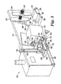
本発明の、テープを印刷し、適用する装置10の好ましい実施形態が、図1および図2に示されている。テープ適用装置10は、テーピングヘッド12と、スタンド14と、を含む。スタンド14は、第1の端部16と、第1の端部16と反対側の第2の端部18と、を含む。スタンド14は、好ましくは、スタンド14の第2の端部18に取付けられて、スタンド14およびテーピングヘッド12を支持する3つの脚20を含む。各脚20は、脚を支持する少なくとも1つの足19を含む。
A preferred embodiment of the
図2に示されているように、テーピングヘッド12は、スタンド14の第1の端部16に取付けられている。好ましくは、テーピングヘッド12は、スタンド14に垂直な第1のロッド110に摺動可能に取付けられている。テープヘッド12は、リードスクリュー118を回転させることによって、第1のロッド110に沿ってどこに移動させてもよい。第1のロッド110は、スライダアセンブリ112によって、第2のロッド114に取付けられている。スライダアセンブリ112は、ピボットを含み、第1のロッド110およびテーピングヘッド12が、第2のロッド114に対して回転することを可能にして、テーピングヘッドが、代替位置に移動して、テープを箱の複数の側面に適用することを可能にする。第2のロッド114は、第1のロッド110に垂直である。リードスクリュー116を回転させることによって、スライダアセンブリ112は、第2のロッド114を上または下に移動させて、床に対してテーピングヘッド12の高さを調整する。テーピングヘッド12は、スタンド14上に、印刷されたテープを物体に適用することを可能にするいかなる配向または位置に取付けてもよい。
As shown in FIG. 2, the taping
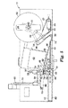
図3および図4は、装置10のテーピングヘッド12の好ましい実施形態を示す。図3および図4は、テーピングヘッド12の部品を説明するのに好都合であり、テーピングヘッド12のテープを示していない。図5−9は、テープを含む、動作中のテーピングヘッド12を示す。
3 and 4 show a preferred embodiment of the taping
テーピングヘッド12は、ベース21を含む。テーピングヘッド12は、ベース21に取付けられたテープ供給ホルダ22を含む。「取付けられた」という用語がここで使用される場合、それは、当該技術分野において知られている、2つのアイテムをともに互いに直接または間接的に取付けるいかなる方法も広く意味するものとする。テープ供給ホルダ22は、好ましくは、テープのロールを横方向に支持する2つの対向するガイド24を含む。代わりに、テープ供給ホルダ22は、個別の長さのテープのスタックを保持するように構成することができる。テーピングヘッド12は、また、駆動ローラ26と、駆動ローラ26を支持する、ベース21に取付けられた支持体28と、を含む。モータ(図示せず)が、駆動ローラ26を駆動する。駆動ローラ26は、テープ供給ホルダ22に取付けられるテープロールから、テープを剥離するか、引張るのを助ける。アイドラローラ30、32が、ベース21に取付けられている。
The taping
アキュムレータ34が、ベース21に取付けられている。1つの好ましい実施形態において、アキュムレータは、アイドラローラ36を備えたダンサアーム34である。ダンサアーム34は、アイドラローラ36と反対側のピボット38によって、ベース21に取付けられている。代わりに、アキュムレータ34は、テープがテーピングヘッド12のテープ経路に沿って蓄積することを可能にする、当該技術分野において知られているいかなる機構であることもできる。たとえば、アキュムレータ34は、リニアスライド、フェストゥーン、またはテープの緩いループであることができる。テーピングヘッド12は、また、ダンサアーム34に隣接して配置された、ベース21に取付けられたセンサ44を含む。適切なセンサ44の一例が、部品番号Ni−4−S12−AN6X−H114で、ミネソタ州ミネアポリス(Minneapolis,Minnesota)に位置するターク・インコーポレイテッド(Turk Inc.)から、近接センサとして市販されている。
An
図3は、第1の位置にあるダンサアーム34を示す。ダンサアーム34は、第1の位置から代替位置または第2の位置に反時計回りに旋回すると、センサ44をトリガする。ダンサアーム34は、ダンサアーム34を第1の位置にバイアスするスプリング(図示せず)を含む。センサ44がトリガされると、信号が駆動ローラ26上のモータに送られ、ローラ26の回転を開始して、テープ供給ロールからテープを引張る。(図5は、アキュムレータ34の第1の位置を実線で示し、アキュムレータ34の第2の位置を点線で示す。)ダンサアーム34、駆動ローラ26、アイドラローラ30、32、およびセンサ44は、テープ供給ホルダ22からプリンタ40の入口にテープを供給するのを助けるように構成され、一方、プリンタは、テープ上に印刷する。別の好ましい実施形態において、テーピングヘッド12は、テープがプリンタの方に引張られているとき、テープがローラの周りにぴんと張られると、検知するロードセルセンサを備えたローラを含むことができる(アキュムレータ34の代わりに)。ローラ内のセンサが、テープがローラの周りをプリンタの方に引張られていることを検知すると、信号が駆動ローラ26上のモータに送られ、ローラ26の回転を開始して、テープ供給ロールからテープを引張る。好ましい実施形態のいずれにおいても、テーピングヘッドは、プリンタ40が印刷を開始すると、テープ供給ロールからテープを引張り始める何らかのタイプの機構を含む。これは、テープを、プリンタ40に、均一な、低張力態様で送出する。代わりに、当該技術分野において知られている他のテープ供給機構を使用してもよい。
FIG. 3 shows the
テーピングヘッド12は、ベース21に取付けられたプリンタ40を含む。プリンタ40は、好ましくは、プリンタの出口に駆動ローラ41またはプラテンローラ41を含む。好ましくは、駆動ローラ41は、テープが、駆動ローラ41と反対側のプリントヘッドによって印刷されているとき、テープの支持表面またはプラテンとして役立つ。駆動ローラ41は、また、回転するとき、印刷されたテープをプリンタの出口から押出す。適切なプリンタ40の例としては、カリフォルニア州サニーベール(Sunnyvale,California)に位置するサトー・アメリカ・インコーポレイテッド(Sato America Inc.)からモデル番号M8485Seで市販されている熱転写プリンタ、または、フロリダ州オーランド(Orlando,Florida)に位置するデータマックス・インコーポレイテッド(Datamax Inc.)からモデル番号PE−42で市販されている熱転写プリンタ、または、ペンシルバニア州フィラデルフィア(Philadelphia,Pennsylvania)に位置するノベックスOEMプリンタズ・アンド・ラベラーズ(NOVEXX OEM Printers and Labellers)からモデルDPMで市販されている熱転写プリンタが挙げられる。プリンタが、印刷されたテープをプリンタの出口から押出すテープ駆動ローラ41を有さない場合、テープ引張り装置(以下で説明される)は、独立して、プリンタからテープを引張ることができる。この場合、そのタイプのプリンタは、被駆動プラテンローラを有さないとしても、プリンタの出口でアイドルプラテンローラを含んでもよい。
The taping
テーピングヘッド12は、プリンタ40の出口に隣接して配置された、ベース21に取付けられたカッタ46を含む。カッタ46は、プリンタ40がテープ上に印刷し、テープがプリンタを出た後、印刷されたテープを切断する。一実施形態において、カッタ46は、好ましくは、上部ブレード50と、下部ブレード48と、を含む。上部ブレード50は、上部ブレード支持体54によってベース21に摺動可能に取付けられ、下部ブレード48は、下部ブレード支持体52によってベース21に取付けられている。好ましくは、両方のブレード48、50は、テープがブレードに粘着しないようにするのを助け、かつ、ブレードがテープを切断するときにテープからブレードへの接着剤の移動を最小にするために、フルオロポリマーまたは機械油などの非粘着性コーティングでコーティングされている。カッタ46は、また、好ましくは空気シリンダであるアクチュエータ56を含む。アクチュエータ56は、上部ブレード支持体54およびしたがって上部ブレード50を、ガイド58に沿って、下部ブレード48の方に、垂直方向に移動させる。下部ブレード48および下部ブレード支持体52は、静止している。代わりに、アクチュエータは、両方のブレード48、50を移動させて、テープを切断することができる。代わりに、アクチュエータは、下部ブレード48を上部ブレード50の方に移動させることができる。上部ブレード50および下部ブレード48は、好ましくは、互いにオフセットであり、それにより、アクチュエータ56が上部ブレード支持体54を作動させると、はさみの1対のブレードと同様に、上部ブレードは下部ブレード48の隣に摺動する。代わりに、テープカッタは、当該技術分野において知られているいかなるカッタ、たとえば、シングルブレード、ホットワイヤカッタ、またはレーザであることができる。
The taping
テーピングヘッド12は、カッタ46に隣接した、ベース21に取付けられたテープ適用装置60を含む。テープ適用装置は、印刷されたテープがプリンタ40を出た後、印刷されたテープを一時的に保持し、次に、印刷されたテープを、物体、好ましくはパッケージまたは箱に適用する。テープ適用装置60は、第1の位置(図3に示されている)と、印刷されたテープを物体に適用するための、物体に隣接した第2の位置(図9に示されている)との間で、適用装置経路に沿って移動可能である。テープ適用装置60は、アクチュエータ68およびガイド70の使用によって、これらの2つの位置の間で移動する。好ましくは、アクチュエータ68は、空気シリンダである。好ましくは、テープ適用装置60は、真空システムを含む。真空システムは、印刷されたテープを保持するために、真空ボックス62に取付けられた真空源64を含む。好ましくは、真空源64は、2つの異なったタイプの真空源を含む。第1の真空源は、低真空高フロー源である。このタイプの真空源64の適切な例が、ブランドデイトン(Dayton)、モデル番号4C548で、ミネソタ州セント・ポール(St.Paul,Minnesota)に位置するグレーンジャー・インダストリアル・サプライ(Grainger Industrial Supply)から、ファンとして市販されている。第2の真空源は、高真空低フロー源である。このタイプの真空源の適切な例が、マサチューセッツ州ヒンガム(Hingham,Massachusetts)に位置するPIAB USAから、ブランドPIAB、モデル番号M−20で、真空ポンプとして市販されている。真空システム60は、好ましくは、ある長さの印刷されたテープを物体に最初に接着するのを助け、かつ、印刷されたテープが適用されるときに印刷されたテープをワイプダウンする(wiping down)のを助けるワイプダウンプレート(wipe down plate)65を含む。ワイプダウンプレート65は、好ましくは、テープを適用するためにワイプダウンプレート65を移動させるアクチュエータ61を含む。装置10は、印刷されたテープが物体に適用された後に印刷されたテープをバフ仕上げする、任意のバフ仕上げアセンブリを含むことができる。
The taping
テーピングヘッド12は、テープ適用装置60の下に配置された、ベース21に摺動可能に取付けられたテープ引張り装置72を含む。テープ引張り装置は、印刷されたテープがプリンタ40を出るとき、印刷されたテープを引張る。テープ引張り装置72は、プリンタ40の出口に隣接した第1の位置から、プリンタ40の出口から遠い第2の位置に、テープ引張り装置を移動させるアクチュエータ80(図5−9に示されている)を含む。好ましくは、アクチュエータ80は、空気シリンダである。
The taping
図4は、テープ適用装置60およびテープ引張り装置72をより詳細に説明するのに好都合である。上述されたように、テープ適用装置60は、低真空高フロー源および高真空低フロー源(ひとまとめにして真空源64として示されている)と、真空源64に取付けられた真空ボックス62と、真空ボックス62に取付けられたワイプダウンプレート65と、を含む。低真空高フロー源は、真空ボックス62を通して、かつワイプダウンプレート65全体にわたって配列された穴66を通して、真空を提供する。好ましくは、ワイプダウンプレート65は、カッタ46に最も近くに配置された少なくとも2つの穴67を含む。高真空低フロー源は、真空ボックス62を通して、かつ穴67を通して、真空を提供する。テープ適用装置60が、テープをテープ適用装置60に保持するために、両方のタイプの真空源を含むことが好ましい。高真空低フロー源のみが含まれる場合、真空ボックスの穴はすべて、テープによって被覆される必要がある。穴がすべて被覆されていない場合、真空は失われ、テープ適用装置は、テープを適切に保持することができない。低真空高フロー源のみが含まれる場合、テープは、テープ適用装置によって確実にまたは十分に保持されない。両方の真空源を使用することによって、低真空高フロー源は、真空ボックス62全体にわたる穴66を通して、テープを適用装置に穏やかに保持し、高真空低フロー源は、穴67を通して、テープを適用装置に確実に保持する。テープを、テープカッタ46に最も近くで、テープ適用装置60に強く保持することが好ましく、というのは、そうでなければ、カッタ46がテープを切断した後、テープが真空ボックス62上で位置を変えることがあるからである。さらに、テープは、通常、2つの穴67を被覆し、その結果、真空は失われない。
FIG. 4 is convenient for explaining the
上で説明されたように、テープ引張り装置72は、好ましくは、テープグリッパ74と、テープグリッパ74をロッド82に沿って移動させるアクチュエータ80と、を含む。テープグリッパ74は、好ましくは、示された実施形態において静止したままである上部ジョー76と、アクチュエータ84によって垂直に移動される下部ジョー78と、を含む。好ましくは、アクチュエータ84は、空気シリンダである。下部ジョー78は、テープが駆動ローラ41からプリンタ40を出るとき、アクチュエータ84によって上部ジョーの方に移動されて、テープ上でジョーを閉じ、かつ、テープの端部を把持する。代わりに、上部ジョー76が移動し、下部ジョーが静止するか、または、両方のジョー76、78が移動して、テープ上でジョーを閉じ、かつ、テープの端部を把持してもよい。好ましくは、下部ジョー78は、テープからの接着剤が下部ジョー78に粘着しないようにするのを助けるために、フルオロポリマーまたはシリコーンのコーティングなどの、その表面に沿った非粘着性コーティングを含む。テープ引張り装置72は、好ましくは、テープをプリンタから適切に引張るのに十分なだけのテープ端部を把持するが、底部ジョー78がテープ上の接着剤に粘着するように多量すぎるテープを把持しないように構成されている。たとえば、ジョー76、78は、テープがプリンタ40を出るとき、テープの長さの0.25から0.50インチ(0.635cmから1.27cm)を把持する。下部ジョー78とテープ上の接着剤との間の接触表面積を低減するために、下部ジョー78は、歯、溝、または他の表面修正を含むことができる。しかし、テープ引張り装置がテープから適切に離脱することができる限り、プリンタから延在しているテープのどの部分も、テープ引張り装置によって把持することができる。
As described above, the
グリッパに関して、「上部」および「下部」ジョーは、上または下に対するいかなる配向も示唆しない。用途によって、グリッパは、横向きに配向してもよいし、下部ジョーが上部ジョーより上になるように配向してもよい。 With respect to the gripper, the “upper” and “lower” jaws do not suggest any orientation relative to the top or bottom. Depending on the application, the gripper may be oriented sideways or so that the lower jaw is above the upper jaw.
テープグリッパ74は、ロッド82と摺動可能に係合するスライダ85に取付けられている。アクチュエータ80は、スライダ86およびしたがってテープグリッパ74を、テープカッタ46およびプリンタ40に隣接した第1の位置と、第2の位置との間で、テープカッタ46およびプリンタ40から離れてロッド82の反対側の端部の方に移動させる。テープ引張り装置72は、第1の位置から、第1の位置と反対側の第2の位置に移動するとき、テープを、プリンタ40から、テープ適用装置60の経路の下または経路内で引張る。好ましくは、テープ引張り装置72が第2の位置にあるとき、それは、テープ適用装置の動作のラインから明らかであり、したがって、テープ適用装置が、第1の位置から第2の位置に移動して、テープを物体に適用するとき、テープ適用装置60は、テープ引張り装置72から妨害されることなく移動することができる。
The
図5は、テーピングヘッド12を通る好ましいテープ経路を説明するのに好都合である。テープロール92が、テープガイド24によって支持されたテープ供給ホルダ22上に取付けられている。テープ90は、バッキング86と、バッキング86上の接着剤88と、を含む。適切なテープの一例が、ミネソタ州セント・ポール(St.Paul,Minnesota)に位置する3Mカンパニー(3M Company)から、スコッチ(Scotch)ブランドテープ、No.3340として市販されている。テープ90は、好ましくは、テーピングヘッド12内の次のテープ経路に沿って移動し、すなわち、a)テープ供給ホルダ22から駆動ローラ26に、b)次に、アイドラローラ30に、c)次に、ダンサアーム34上のアイドラローラ36に、d)次に、アイドラローラ32に、e)次に、プリンタ40の入口に、f)次に、プリンタを通って、プリンタ40の出口における駆動ローラ41に、g)次に、テープカッタ46の上部ブレード50と下部ブレード48との間に、h)次に、テープ引張り装置の上部ジョー76および下部ジョー78に移動し、これは、テープを、テープ適用装置60の経路にわたって引張る。テープの新たなロール92をテープ供給ホルダ22上に装填するとき、テープは、上で略述されたテープ経路に従って、テーピングヘッド12を最初に通される。
FIG. 5 is convenient to illustrate the preferred tape path through the taping
テープを印刷し、適用する装置10の動作の好ましい順序は、図5−9に示されており、次の通りである。
A preferred sequence of operation of the
図5は、プリンタ40がテープ90上の印刷を開始する前のテーピングヘッド12を示す。この位置を得るために、第1のアクチュエータ80は、テープ引張り装置72を、ロッド82に沿って(図中右側に)、プリンタ40の出口に隣接した第1の位置に、かつテープカッタ46のブレード48、50の間に、先に移動させた。また、第5のアクチュエータ84は、テープ引張り装置72の下部ジョー78を先に移動させて、上部ジョー76と下部ジョー78との間でテープ90の第1の端部96を把持した。いったんこの位置にあると、第1のアクチュエータ80は、力を加えて、テープ引張り装置をプリンタから離して(図中左側に)移動させる。しかし、この力は、プリンタ40が印刷していないときにプリンタ40からテープ90を引張るほど十分に大きくない。グリッパは、プリンタがプリンタの出口からテープを供給するとき、移動する。この位置において、テープ90は、張力下で保持されている。
FIG. 5 shows the taping
図6は、プリンタ40がテープ90上に印刷しているときのテーピングヘッド12を示す。好ましくは、プリンタ40が印刷する前に、テープ適用装置60の真空システムをオンにする。プリンタ40が印刷するとき、プラテン駆動ローラ41は、回転して、テープ90をプリンタ40の出口から押出す。テープ90が、テープ引張り装置72によって張力下で引張られているので、テープ引張り装置は、プリンタがより多くの印刷されたテープ90を供給し続けるとき、プリンタから離れて、かつ適用装置経路にわたって移動する。この時間の間、テープは、張力下で連続しており、かつ、プリンタ出口から直接引張られる。テープは、プリンタ出口から張力下で直接引張られるので、駆動ローラ41「に巻付く」傾向がない。この構成は、本出願の背景部分で詳述されたプラテンローラまたは駆動ローラ「巻付き」問題を回避する。テープ引張り装置72を使用しなければ、テープは、駆動ローラ41が回転するとき、駆動ローラ41に巻付くことがある。テープ引張り装置72は、プリンタ40がテープの印刷を停止するまで、矢印で示されたようにプリンタから離れて移動し続け、テープ90を、テープ適用装置60の経路を通して引張り、かつ、テープを張力下で保つ。いったんプリンタが印刷を停止すると、テープ引張り装置72は、テープ90を引張り続け、テープを張力下で保つ。この時間において、テープ引張り装置72は、プリンタ40と反対側のロッド82の端部の近くにある第2の位置の方に移動している。テープ引張り装置72は、第1の位置から第2の位置の方に移動するとき、テープ90を、テープ適用装置60の経路を過ぎて引張る。テープ適用装置の経路は、以下でより詳細に説明されるように、テープ適用装置60の、その第1の位置から、その第2の位置への移動である。
FIG. 6 shows the taping
プリンタ40が、印刷を停止した後、もはやテープをプリンタの出口から供給していないと、信号が送られ、第5のアクチュエータ84を動作させて、テープ引張り装置の下部ジョー78を上部ジョー76から離して移動させる。その際に、印刷されたテープは、テープ引張り装置72から解放され、もはや張力下ではない。印刷されたテープの長さによって、テープ引張り装置は、後で移動して印刷されたテープを適用するテープ適用装置の経路から移動する必要があるであろう。たとえば、印刷されたテープ90の長さが、テープ適用装置60の長さより短い場合、テープがテープ引張り装置72によって解放された後、アクチュエータ80は、テープ引張り装置を、テープ適用装置の経路から、プリンタから離して、バー82の端部の近くにある第2の位置の方に押し続けてもよい。テープ適用装置60の真空システムは、先にオンにされたので(印刷工程前)、印刷されたテープ90を真空ボックス62の方に引寄せる。この工程は、図7に示されており、テープ適用装置60は、印刷されたテープを保持している。テープ90の印刷された面は、ワイプダウンプレート65と接触している。穴67を通る高真空低フロー真空は、テープカッタ46およびプリンタ40に最も近いテープの部分を強く保持し、一方、穴66を通る低真空高フロー真空は、テープの他の部分を緩く保持する。
When the
図8は、テープを切断するカッタ46を示す。いったん、プリンタ40が、印刷またはテープの供給を停止し、その結果、テープ引張り装置72が、移動を停止し、テープ適用装置60の下から出ると、信号がテープカッタ46上の第3のアクチュエータ56に送られ、上部ブレード50を下方に作動させて、下部ブレード48の隣に摺動させて、テープ90を切断する。テープ90が切断された後、第1の端部96と、第1の端部96と反対側の第2の端部98と、を有する、ある長さのテープ94が、真空システム60の方に引寄せられ、真空源64によって所定位置に保持される。装置10は、さまざまな長さのテープを切断するように構成されている。テープが切断された後、駆動ローラ41は、図8に示されているように、逆方向(時計回りに)に回転して、テープをカッタ46から離して後退させる。駆動ローラ41が逆方向に回転するとき、アキュムレータ34は、時計回りに回転することによって、付加的なテープに対応する。アキュムレータ34は、テープ上の張力を戻して、テープが駆動ローラ41に接着するか巻付くことがないようにする。好ましくは、駆動ローラ41は、テープ90を0.1から1インチ(0.254cmから2.54cm)後退させ、より好ましくは、テープ90を0.08から0.12インチ(0.2から0.3cm)後退させる。駆動ローラ41がテープをカッタから離して後退させることに、3つの利点がある。第1に、テープ90上の接着剤は、カッタブレードに粘着する傾向を有することがあり、テープをカッタから離して後退させることによって、これは、テープをカッタブレードから引張るのを助ける。第2に、テープ90の端部は、テープを後退させた後、ほとんど常に同じ位置にあり、したがって、これは、テープ引張り装置72が次のサイクルでテープの端部を把持するための予測可能な位置を提供する。最後に、テープを後退させることによって、それは、テープの第1の端部により近い位置で印刷を開始することによってテープの印刷領域を最大にするのを助ける。
FIG. 8 shows a
テーピングヘッド12は、また、プリンタ40が印刷を終了した後、テープを供給し続けてもよい。たとえば、テーピングヘッド12が6インチ(15.24cm)の長さの印刷されたテープを作っている場合、プリンタは、印刷せずに、もう半インチ(1.27cm)テープを供給し続け、6インチの長さの第2の端部が、カッタ46のブレードにより近くに位置決めされるようにしてもよい。カッタ46がテープの長さを切断して、6インチの長さのテープを形成した後、プリンタの駆動ローラは、逆になり、テープの余分な半インチをプリンタに引き戻して、再び印刷を開始する。
The taping
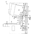
図9は、適用装置経路に沿って第1の位置から第2の位置に移動して適用するテープ適用装置60を示し、テープの切断長さ94は、好ましくはパッケージまたは箱である物体100に最初に適用されている。テープ適用装置は、適用装置経路に沿って移動するとき、第1の位置から第2の位置に移動したとき、前のテープ引張り装置経路に垂直に交差する。第2のアクチュエータ68は、テープの長さが真空システムによって保持された状態で、テープ適用装置60を移動させる。テープ適用装置60が第2の位置に移動すると、第4のアクチュエータ61は、ワイプオンプレート(wipe on plate)65を旋回させて、テープの第2の端部98を箱100に接着する。テープの切断長さの第2の端部98の接着剤88は、テープを箱100に粘着する。
FIG. 9 shows a
図10は、ある長さのテープ94を箱に適用し終えている適用装置60を示す。箱が右側に移動するとき、ワイプオンプレート65は、テープ94の第1の端部96を含む、箱に沿ったテープ94の全長をワイプダウンする。テープの切断長さの接着剤88は、テープを箱100に粘着する。
FIG. 10 shows the
本出願の教示に基いて、当業者は、装置または上述された動作の順序にさまざまな修正を行うことができる。たとえば、一実施形態において、テープ引張り装置72がテープをテープ適用装置60の下で引張っている全時間の間、真空源64が動作する代わりに、テープ引張り装置72がテープを解放する直前に、真空源64をオンにして動作させることができる。別の実施形態において、テープ引張り装置72は、テープの接着剤面を把持するためのような1つのみのジョーもしくは部材またはスティックオン(stick−on)プレートなどの、テープを引張るための任意の適切な機構を含むことができる。いったん、プリンタがテープの印刷を終了して、テープが静止したままになると、テープ引張り装置72は、移動し続けて、ジョー、部材、またはスティックオンプレートを、テープの接着剤面から離脱させることができる。別の実施形態において、テープ引張り装置72は、テープの接着剤面を把持するための2つのジョー76、78の代わりに、ローラを含むことができる。この実施形態において、テープ引張り装置がローラをテープの接着剤面に取付けるとき、およびテープ引張り装置が第2の位置に移動するとき、ローラは静止したままである。重要なのは、テープがテープ適用装置経路にわたって引張られるとき、引張り装置が張力下でテープを維持することである。いったん第2の位置にあると、テープ引張り装置は、左側に移動し続け、ローラは、回転して、ローラからテープを解放する。別の実施形態において、テープ引張り装置72は、プリンタからテープを引張るための、ローラまたはジョーのいかなる組合せも含むことができる。
Based on the teachings of this application, one of ordinary skill in the art can make various modifications to the apparatus or sequence of operations described above. For example, in one embodiment, instead of the
さらに別の実施形態において、真空システムテープ適用装置がある長さのテープ94を一時的に保持する代わりに、テープ適用装置は、静電荷によって、感圧接着剤または当該技術分野において知られている他の手段によって、テープを一時的に保持することができる。この実施形態において、テープ適用装置60は、第1の位置と第2の位置との間の中間位置に移動して、印刷されたテープをテープ適用装置に一時的に接着し、次に、第2の位置に進んで、印刷されたテープを箱に接着することができる。別の実施形態において、テープ適用装置60は、ワイプオンプレート65を含む必要がない。代わりに、テープ適用装置60は、印刷されたテープをパッケージまたは箱上にタンピングすることによって、印刷されたテープ94を箱に取付けることができる。テープ適用装置60が印刷されたテープをパッケージまたは箱上にタンピングする間、箱は静止していてもよいし、または、テープ適用装置が印刷されたテープを箱上にタンピングするとき、テープ適用装置60は、箱が移動すると同じ方向に移動することができる。別の実施形態において、テープ適用装置は、静止し、箱が適用装置を過ぎて移動するとき、印刷されたテープを箱上にタンピングすることができる。別の実施形態において、テープ適用装置は、印刷されたテープを適用装置から箱上にブローして、印刷されたテープを箱に適用する空気源を含むことができる。別の実施形態において、テープカッタ46およびテープ適用装置60は、1つの機構であることができる。この実施形態において、シングルブレードがテープ適用装置60に取付けられる。テープ適用装置およびブレードが、テープを適用するために、印刷されたテープより上の第1の位置から、第2の位置に移動するとき、ブレードは、テープを通って切断し、テープ適用装置の真空システムは、切断されたテープを真空ボックスに引寄せる。次に、テープ適用装置およびブレードは、第2の位置に移動して、印刷されたテープを箱に適用する。ブレードは、適用装置が印刷されたテープを箱に適用するときに、箱と接触しないように構成することができる。別の実施形態において、テープカッタは、プリンタの出口より下に配置された、テープヘッドに取付けられたシングルブレードまたはホットワイヤカッタであることができる。この実施形態において、テープ適用装置は、第1の位置から第2の位置に移動するとき、印刷されたテープ94を、静止したブレードまたはホットワイヤを過ぎて運び、したがって、テープを通って切断する。
In yet another embodiment, instead of temporarily holding a length of
テープ引張り装置72を移動させる第1のアクチュエータ80、テープ適用装置60を移動させる第2のアクチュエータ68、テープカッタを移動させる第3のアクチュエータ56、ワイプオンプレート65を移動させる第4のアクチュエータ61、およびテープ引張り装置72の下部ジョー78を移動させる第5のアクチュエータ84の適切なアクチュエータの例が、ミネソタ州イーデン・プレーリー(Eden Prairie,Minnesota)に位置するSMCコーポレイション・オブ・アメリカ(SMC Corporation of America)からの空気シリンダ、モデル番号CM2C25−100A、および、ニューヨーク州ハーパーグ(Hauppauge,New York)に位置するフエスト・コーポレイション(Festo Corporation)から入手可能な空気シリンダ、モデル番号DSNU−16−250−PPV−Aとして市販されている。装置10は、5のアクチュエータを含むように示されているが、この装置は、いかなる数のアクチュエータを含んでもよい。
A
好ましくは、テープを印刷し、適用する装置10は、さまざまなアクチュエータ、さまざまなセンサ、さまざまなモータ、およびプリンタを、特定の順序で動作させる、プログラム可能な論理コントローラを含む。市販のコントローラの適切な例が、ウィスコンシン州ミルウォーキー(Milwaukee,Wisconsin)に位置するアレン・ブラドリー(Allen Bradley)から、ブランド名マイクロロジックス(Micrologix)、モデル番号1000 1761−L32BBで、コントローラとして入手可能である。
Preferably, the
テープを印刷し、適用する装置10は、情報をある長さのテープ上に印刷し、次に、その長さのテープを、物体、好ましくは箱またはパッケージに適用する。テープ上に印刷される情報は、テープが接着されるパッケージまたは箱についての非常にさまざまな情報を含むことができる。たとえば、印刷されたある長さのテープは、パッケージまたはパッケージ内のアイテムのアイデンティティであってもよい。それは、パッケージの発送先、移動履歴について、またはパッケージ内のアイテムについて、またはアイテムもしくはパッケージの重量についての情報を含んでもよい。印刷されたある長さのテープは、内容物の目録、パッケージ内のアイテムの価格および製造業者、いつパッケージが密封されたか、パッケージの内容物に関する危険情報、または内容物もしくはパッケージの輸送コード、パッケージの必要な保管条件、または内容物の製造の日付、または内容物に関する保証情報などの、パッケージの内容物についての情報を含んでもよい。
The
ここで、本発明を、そのいくつかの実施形態に関して説明した。先の詳細な説明および例は、理解を明確にするためにのみ示した。それらから、不要な限定が理解されるべきではない。ここに引用された特許および特許出願はすべて、引用によりここに援用する。本発明の範囲から逸脱することなく、説明された実施形態に多くの変更を行うことができることが、当業者には明らかであろう。したがって、本発明の範囲は、ここで説明された厳密な詳細および構造に限定されるべきではないが、むしろ、特許請求の範囲の文言によって説明された構造、およびそれらの構造の均等物によって限定されるべきである。 The present invention has now been described with respect to several embodiments thereof. The foregoing detailed description and examples have been given for clarity of understanding only. From these, unnecessary limitations should not be understood. All patents and patent applications cited herein are hereby incorporated by reference. It will be apparent to those skilled in the art that many changes can be made in the embodiments described without departing from the scope of the invention. Accordingly, the scope of the invention should not be limited to the precise details and structures described herein, but rather is limited by the structures described by the language of the claims and the equivalents of those structures. It should be.
Claims (39)
テープ上に印刷するプリンタと、
前記プリンタから印刷されたテープを引張るテープ引張り装置と、
前記印刷されたテープを物体に適用するテープ適用装置と、を含む、テープを印刷し、適用する装置。 A tape supply holder;
A printer that prints on tape;
A tape pulling device for pulling the tape printed from the printer;
An apparatus for printing and applying a tape, comprising: a tape applying apparatus that applies the printed tape to an object.
プリンタと、
グリッパと、
前記グリッパを、前記プリンタに隣接した第1の位置と、前記プリンタから遠い第2の位置との間で移動させる第1のアクチュエータと、
テープ適用装置と、を含む、テープを印刷し、適用する装置。 A tape supply holder;
A printer,
A gripper,
A first actuator for moving the gripper between a first position adjacent to the printer and a second position remote from the printer;
A device for printing and applying a tape, including a tape applying device.
プリンタで前記テープ上に印刷する工程と、
テープ引張り装置で前記プリンタから張力下で印刷されたテープを引張る工程と、
印刷されたテープを物体に適用する工程と、を含む、テープを印刷し、適用する方法。 Providing a tape; and
Printing on the tape with a printer;
Pulling the tape printed under tension from the printer with a tape tensioner;
Applying the printed tape to the object, and printing and applying the tape.
40. The method of claim 38, wherein the object is a package with contents, and the printing step includes printing information corresponding to the contents on the tape.
Applications Claiming Priority (2)
| Application Number | Priority Date | Filing Date | Title |
|---|---|---|---|
| US10/121,536 US6884312B2 (en) | 2002-04-12 | 2002-04-12 | Apparatus for printing and applying tape and methods of printing and applying tape |
| PCT/US2003/005929 WO2003086761A2 (en) | 2002-04-12 | 2003-02-27 | An apparatus for printing and applying tape and methods of printing and applying tape |
Publications (2)
| Publication Number | Publication Date |
|---|---|
| JP2005522356A true JP2005522356A (en) | 2005-07-28 |
| JP2005522356A5 JP2005522356A5 (en) | 2006-04-06 |
Family
ID=28790355
Family Applications (1)
| Application Number | Title | Priority Date | Filing Date |
|---|---|---|---|
| JP2003583748A Withdrawn JP2005522356A (en) | 2002-04-12 | 2003-02-27 | Apparatus for printing and applying tape, and method for printing and applying tape |
Country Status (9)
| Country | Link |
|---|---|
| US (1) | US6884312B2 (en) |
| EP (1) | EP1494871A2 (en) |
| JP (1) | JP2005522356A (en) |
| KR (1) | KR20040108729A (en) |
| CN (1) | CN1652941A (en) |
| AU (1) | AU2003219920A1 (en) |
| BR (1) | BR0308868A (en) |
| CA (1) | CA2481440A1 (en) |
| WO (1) | WO2003086761A2 (en) |
Cited By (3)
| Publication number | Priority date | Publication date | Assignee | Title |
|---|---|---|---|---|
| JP2018070255A (en) * | 2016-11-04 | 2018-05-10 | 株式会社寺岡精工 | Label sticking apparatus |
| JP2019106871A (en) * | 2017-10-30 | 2019-06-27 | コマツクス・ホールデイング・アー・ゲー | Method for connecting first cable with second cable, cable configuration, and cable connection device for connecting first cable with second cable |
| WO2021010315A1 (en) * | 2019-07-17 | 2021-01-21 | 大王製紙株式会社 | Electronic tag sticking apparatus |
Families Citing this family (34)
| Publication number | Priority date | Publication date | Assignee | Title |
|---|---|---|---|---|
| US7380688B2 (en) * | 2003-02-07 | 2008-06-03 | Robert Scott Fore | Hand-held adhesive label dispenser |
| US20060157202A1 (en) * | 2003-06-05 | 2006-07-20 | Arippol Giuseppe J | System to bring adhesive backed articles into assembled association with products |
| WO2005039986A1 (en) * | 2003-10-29 | 2005-05-06 | Hm Labelling A/S | Method and apparatus for application of linerless labels |
| US7156140B1 (en) * | 2004-06-08 | 2007-01-02 | Axon Corporation | Heat-shrinkable banding apparatus and method |
| US7270491B2 (en) * | 2004-10-25 | 2007-09-18 | Lintec Corporation | Code label printer, method thereof and readouted printed-code verifying system |
| ITMI20042304A1 (en) * | 2004-11-30 | 2005-02-28 | Sitma Spa | DEVICE AND METHOD OF HANDLING AND PRINTING FOR LABELS POWERED BY TABLES |
| US8228198B2 (en) * | 2005-08-19 | 2012-07-24 | Adasa Inc. | Systems, methods, and devices for commissioning wireless sensors |
| US9272805B2 (en) | 2005-08-19 | 2016-03-01 | Adasa Inc. | Systems, methods, and devices for commissioning wireless sensors |
| US7551087B2 (en) * | 2005-08-19 | 2009-06-23 | Adasa, Inc. | Handheld and cartridge-fed applicator for commissioning wireless sensors |
| US20100001848A1 (en) * | 2007-06-22 | 2010-01-07 | Mcallister Clarke | Secure Modular Applicators to Commission Wireless Sensors |
| US8159349B2 (en) * | 2005-08-19 | 2012-04-17 | Adasa Inc. | Secure modular applicators to commission wireless sensors |
| US7830258B2 (en) * | 2005-08-19 | 2010-11-09 | Adasa, Inc. | Systems, methods, and devices for converting and commissioning wireless sensors |
| US7665498B2 (en) * | 2005-11-15 | 2010-02-23 | 3M Innovative Properties Company | Tape monitoring system |
| US7938159B2 (en) * | 2006-10-27 | 2011-05-10 | Chris Peter Makar | Tape applicators |
| US7832440B2 (en) * | 2007-01-15 | 2010-11-16 | Masco Corporation | Machine and method for applying pressure sensitive sample chips to a card |
| US20090288534A1 (en) * | 2008-05-23 | 2009-11-26 | Mccoy Jody J | Inline tape cutter |
| WO2011081624A1 (en) * | 2009-12-30 | 2011-07-07 | Avery Dennison Corporation | Coupling for mounting a labeling machine and method of adjusting a labeling machine |
| US8882955B2 (en) * | 2011-07-07 | 2014-11-11 | Superior Tape & Label Incorporated | Automated labeling method and label supply therefor |
| US20130138391A1 (en) | 2011-11-30 | 2013-05-30 | Zih Corp. | Platen wrap detection |
| ES2566364T3 (en) * | 2012-09-28 | 2016-04-12 | Kronoplus Technical Ag | Apparatus and procedure for applying labels to boxes |
| US8616259B1 (en) | 2012-11-30 | 2013-12-31 | Nulabel Technologies, Inc. | Automated labeling apparatus using labels having a fluid activatable adhesive |
| US9809730B2 (en) * | 2015-06-10 | 2017-11-07 | Upm Raflatac Oy | Printable label comprising a clear face layer and a clear adhesive layer |
| US9925800B2 (en) * | 2015-11-02 | 2018-03-27 | A2N Incorporated | Adhesive film printing apparatus |
| US11007794B2 (en) * | 2015-11-02 | 2021-05-18 | A2N Incorporated | Adhesive film printing apparatus |
| CN105523244B (en) * | 2016-01-07 | 2018-05-01 | 东莞市顺丰纸品制造有限公司 | Automatic carton labelling machine |
| TW201811518A (en) * | 2016-06-21 | 2018-04-01 | 美商3M新設資產公司 | Conversion and application of material strips |
| US20190375179A1 (en) * | 2017-01-27 | 2019-12-12 | Sfc Ltd. | Method and apparatus for cutting and taping a substrate and a product made by the method |
| CN107352107A (en) * | 2017-08-09 | 2017-11-17 | 苏州弘毅辉自动化设备有限公司 | Label printing cuts attaching all-in-one |
| US10597186B2 (en) | 2018-06-21 | 2020-03-24 | John Bean Technologies Corporation | Produce label printer and applicator |
| CN108820422B (en) * | 2018-06-29 | 2023-08-22 | 常州瑞杰新材料科技有限公司 | Polygonal packing box with in-mold label and manufacturing method thereof |
| CN109850302A (en) * | 2018-12-11 | 2019-06-07 | 中国民航大学 | A kind of automatic labeling mechanism of Aviation hand baggage |
| TWI734610B (en) * | 2020-09-14 | 2021-07-21 | 鴻績工業股份有限公司 | Tape supply module and tape mechanism |
| CN113928675B (en) * | 2021-10-29 | 2022-11-08 | 山东至辰信息科技股份有限公司 | Library's books label pastes equipment |
| CN114664093B (en) * | 2022-05-20 | 2022-11-04 | 湖南第一师范学院 | Traffic control system based on computer vision |
Family Cites Families (113)
| Publication number | Priority date | Publication date | Assignee | Title |
|---|---|---|---|---|
| US2532011A (en) | 1946-09-07 | 1950-11-28 | Minnesota Mining & Mfg | Liners and adhesive tapes having low adhesion polyvinyl carbamate coatings |
| US2492908A (en) | 1947-03-22 | 1949-12-27 | New Jersey Machine Corp | Label applying mechanism |
| BE511062A (en) | 1949-10-27 | |||
| US2788625A (en) | 1955-09-27 | 1957-04-16 | Minnesota Mining & Mfg | Tape stapling |
| US2990081A (en) | 1957-09-26 | 1961-06-27 | Minnesota Mining & Mfg | Application of tape to moving objects |
| GB1079233A (en) * | 1963-12-09 | 1967-08-16 | New Jersey Machine Corp | Method and apparatus for feeding labels for application to bottles, containers and the like |
| NL152616B (en) * | 1967-09-13 | 1977-03-15 | Nicolaas Willem Cornelis Jacob | MACHINE FOR MARKING TEXTILE GOODS. |
| US3657051A (en) | 1969-05-27 | 1972-04-18 | Dymo Industries Inc | Transfer printing addressing maching |
| US3561190A (en) | 1969-09-15 | 1971-02-09 | Stapling Machines Co | Carton taping machine |
| US4072224A (en) | 1972-05-24 | 1978-02-07 | The General Electric Company Limited | Printing devices |
| US4001072A (en) | 1972-09-13 | 1977-01-04 | Minnesota Mining And Manufacturing Company | Applicator for pressure-sensitive adhesive fasteners |
| US3963557A (en) | 1974-05-28 | 1976-06-15 | Minnesota Mining And Manufacturing Company | Article transferring apparatus |
| US3905859A (en) | 1974-11-29 | 1975-09-16 | Minnesota Mining & Mfg | Vacuum wheel apparatus for applying tabbed strips of adhesive tape |
| US3989575A (en) | 1975-04-16 | 1976-11-02 | Oliver Machinery Company | Split labeling apparatus |
| US4101366A (en) * | 1975-09-04 | 1978-07-18 | Teraoka Seikosho Co., Ltd. | Electronic digital display scale with label printer |
| DE2651911C3 (en) | 1976-11-13 | 1983-01-20 | Jagenberg-Werke AG, 4000 Düsseldorf | Device for pressing glued labels or foils onto objects |
| US4363685A (en) | 1977-03-11 | 1982-12-14 | Njm, Inc. | Package label and manufacture of same |
| IT1084615B (en) | 1977-04-01 | 1985-05-25 | Marchetti Augusto | PARALLELEPIPED BOX SEALING MACHINE. |
| CA1096341A (en) * | 1978-10-13 | 1981-02-24 | Tadahiro Sakaguchi | Label handling apparatus |
| US4227955A (en) | 1979-01-08 | 1980-10-14 | Fmc Corporation | Article taping system |
| US4256528A (en) | 1979-05-23 | 1981-03-17 | Minnesota Mining And Manufacturing Company | Machine for forming openings sealed by manually removable lengths of tape in can ends |
| GB2071054B (en) | 1979-09-05 | 1983-09-01 | Ezy Wrap Products Pty Ltd | Plastic film dispenser |
| JPS571150A (en) | 1980-05-30 | 1982-01-06 | Koyo Jidoki | High speed feeder |
| US4421817A (en) | 1980-08-29 | 1983-12-20 | Felice Pina | Method for making printable self-adhesive tapes and the self-adhesive tapes obtaned thereby |
| US4321103A (en) | 1980-09-25 | 1982-03-23 | Hi-Speed Checkweigher Co., Inc. | Mechanism for applying merchandising labels to packages/objects of different weights and dimensions |
| DE3041057A1 (en) | 1980-10-31 | 1982-05-13 | Jagenberg-Werke AG, 4000 Düsseldorf | METHOD AND DEVICE FOR APPLYING RIDER LABELS (BANDEROLS) TO CONTAINER CAPS, IN PARTICULAR BOTTLE CAPS |
| US4676859A (en) | 1981-09-28 | 1987-06-30 | Labeling Systems, Inc. | Labeling apparatus |
| EP0083404A1 (en) * | 1981-12-31 | 1983-07-13 | Rabewerk Heinrich Clausing | Soil tilling machine with rotating tools |
| IT1152962B (en) | 1982-06-11 | 1987-01-14 | Manuli Autoadesivi Spa | IMPROVEMENT OF SELF-ADHESIVE TAPES WITH POLYPROPYLENE OR OTHER POLYMER OR OLEFINIC COPOLYMER AND RELATED MANUFACTURING PROCEDURE |
| DE3234556A1 (en) | 1982-09-17 | 1984-05-10 | Lesch, Hans-Bernd, Dipl.-Ing., 8000 München | Labelling device for the preparation of labels and application thereof to packages or the like |
| US4432830A (en) | 1983-02-07 | 1984-02-21 | Intermec Corporation | Label printer having selectable label stock paths |
| US4561921A (en) * | 1983-05-05 | 1985-12-31 | Hobart Corporation | Label applicator and method of label application |
| JPS59217548A (en) | 1983-05-23 | 1984-12-07 | Hitachi Ltd | Thermal transfer recorder |
| EP0170172B1 (en) | 1984-07-24 | 1989-05-17 | Siemens Aktiengesellschaft | Piezoelectric relay |
| US4717621A (en) | 1984-10-01 | 1988-01-05 | Bemis Associates, Inc. | Lettering material for fabric and the like |
| US4784714A (en) | 1986-02-10 | 1988-11-15 | Ricoh Electronics, Inc. | Linerless thermal label printer and applicator |
| US4707211A (en) | 1986-02-10 | 1987-11-17 | Ricoh Electronics, Inc. | Linerless thermal label printer and applicator |
| US4807177A (en) | 1986-06-06 | 1989-02-21 | Ward Richard J | Multiple format hand held label printer |
| US4839742A (en) | 1986-10-13 | 1989-06-13 | Brother Kogyo Kabushiki Kaisha | Reflected-character printing apparatus |
| US4815871A (en) | 1986-11-14 | 1989-03-28 | Varitronic Systems, Inc. | Head control apparatus |
| DE3727667A1 (en) | 1987-08-19 | 1989-03-02 | Ostma Maschinenbau Gmbh | Labelling apparatus |
| FR2622146A1 (en) | 1987-10-26 | 1989-04-28 | Duport Jean Claude | COMPOSITE RIBBON FOR LABEL PRINTING MACHINES AND MACHINE USING SUCH A RIBBON |
| FR2622837B1 (en) * | 1987-11-06 | 1990-03-09 | Hove Eric Van Den | MACHINE FOR AUTOMATICALLY EDITING LABELS AND STAPLING THESE INDIVIDUAL LABELS ON ARTICLES |
| US4976558A (en) | 1987-11-19 | 1990-12-11 | Brother Kogyo Kabushiki Kaisha | Device for feeding recording medium in the longitudinal recording direction |
| US4857134A (en) | 1987-12-03 | 1989-08-15 | Lin Shuh Chin | Structure of carton sealing sticker and cutter |
| US5193926A (en) | 1987-12-21 | 1993-03-16 | Brother Kogyo Kabushiki Kaisha | Apparatus for recording image covered by protective medium |
| US5188469A (en) | 1988-10-14 | 1993-02-23 | Brother Kogyo Kabushiki Kaisha | Tape feed cassette with tape cutter and guide |
| US4889581A (en) | 1988-11-14 | 1989-12-26 | Durable Pakaging Corporation | Carton sealing apparatus |
| US5040461A (en) | 1989-11-17 | 1991-08-20 | Avery International Corporation | Label printing and dispensing apparatus |
| DE3938410A1 (en) | 1989-11-18 | 1991-05-23 | Focke & Co | DEVICE FOR APPLYING AN ADHESIVE STRIP TO A FOLDING CARDBOARD OR THE LIKE |
| US5242888A (en) | 1990-01-25 | 1993-09-07 | Arkwright, Incorporated | Polymeric matrix for thermal transfer recording |
| EP0457309B1 (en) | 1990-05-17 | 1995-03-29 | Seiko Epson Corporation | Tape printing device |
| US5425823A (en) | 1990-08-30 | 1995-06-20 | B.C.E. Technologies | Combination label printer and application device |
| US5286332A (en) | 1990-09-10 | 1994-02-15 | Minnesota Mining And Manufacturing Company | Apparatus for applying an L clip tape to a cartridge |
| US5261996A (en) | 1991-01-25 | 1993-11-16 | Minnesota Mining And Manufacturing Company | Guiding system for a vacuum wheel applicator |
| US5209808A (en) | 1991-02-26 | 1993-05-11 | Imtec, Inc. | Corner label applicator system and method |
| DE9116934U1 (en) | 1991-05-03 | 1994-09-22 | Brother Ind Ltd | Tape cassette for use in a tape printing device and tape printing device |
| JP2551876Y2 (en) | 1991-09-06 | 1997-10-27 | ローム株式会社 | Tape printer using portable printer |
| US5540795A (en) * | 1991-10-07 | 1996-07-30 | Pti, Inc. | Label applicator |
| US5865918A (en) | 1991-10-07 | 1999-02-02 | Pti, Inc. | Label applicator |
| US5304264A (en) * | 1991-11-05 | 1994-04-19 | Automated Packaging Systems, Inc. | Item applicator and method |
| US5379962A (en) | 1992-01-21 | 1995-01-10 | Minnesota Mining And Manufacturing Company | Heated web knife |
| US5227002A (en) | 1992-02-14 | 1993-07-13 | Minnesota Mining And Manufacturing Company | Apparatus for applying tape to an object |
| US5879507A (en) | 1992-02-21 | 1999-03-09 | Apax Corporation | Apparatus for automatically applying adhesive-backed labels to moving articles |
| US5399228A (en) | 1992-02-21 | 1995-03-21 | Best Label Co., Inc. | Apparatus and method for automatically applying adhesive-backed labels to moving articles |
| US5342461A (en) * | 1992-04-14 | 1994-08-30 | Imtec, Inc. | High speed continuous conveyor printer/applicator |
| US5674345A (en) | 1992-07-01 | 1997-10-07 | Moore Business Forms, Inc. | Linerless label printer applicator |
| US5354588A (en) | 1992-07-13 | 1994-10-11 | Moore Business Forms, Inc. | Linerless labels with tie coat |
| US5292713A (en) | 1992-07-15 | 1994-03-08 | Stenzel Herbert J | Linerless thermal and thermal transfer labels |
| US5431763A (en) | 1992-11-19 | 1995-07-11 | Boss Systems, L.L.C. | Linerless labeling system |
| JP3066555B2 (en) | 1993-01-29 | 2000-07-17 | ブラザー工業株式会社 | Tape winding mechanism |
| US5413651A (en) | 1993-03-23 | 1995-05-09 | B&H Manufacturing Company | Universal roll-fed label cutter |
| JP2768211B2 (en) | 1993-04-30 | 1998-06-25 | マックス株式会社 | Tape printer |
| CA2129068A1 (en) | 1993-08-02 | 1995-02-03 | Karl Schroeder | Printing system for linerless labels |
| CH687193A5 (en) | 1993-08-09 | 1996-10-15 | Rothenberger & Co | Fitting device for securing handle to packet |
| US5376418A (en) | 1993-09-13 | 1994-12-27 | Uarco Incorporated | Image protected pressure sensitive label |
| JP3394572B2 (en) | 1993-10-22 | 2003-04-07 | 株式会社サトー | Heat seal label printing method and printer |
| JPH07125374A (en) | 1993-11-02 | 1995-05-16 | King Jim Co Ltd | Layout indication device |
| US5540369A (en) | 1993-12-07 | 1996-07-30 | Moore Business Forms, Inc. | Detaching linerless labels |
| US5437228A (en) | 1994-01-11 | 1995-08-01 | Datasouth Computer Corporation | Method and apparatus for printing adhesive backed media |
| US5478880A (en) | 1994-02-01 | 1995-12-26 | Moore Business Forms, Inc. | Printable release |
| US6199614B1 (en) * | 1994-02-03 | 2001-03-13 | Exact Packaging, Inc. | High speed labeling machine having a constant tension driving system |
| US5661099A (en) | 1994-02-28 | 1997-08-26 | Media Solutions, Inc. | Self-wound direct thermal printed labels |
| US5482593A (en) | 1994-04-05 | 1996-01-09 | Minnesota Mining And Manufacturing Company | High speed applicator for adhesive tape |
| DE4412091A1 (en) | 1994-04-08 | 1995-10-12 | Werner Achilles Gmbh & Co Kg G | Method and appliance for producing esp. printed sheets |
| CA2147535A1 (en) | 1994-04-29 | 1995-10-30 | Albert Wurz | Label applicator for articles of varying dimensions detected and processed by sensors and a cpu |
| US5497701A (en) | 1994-05-16 | 1996-03-12 | Datasouth Computer Corporation | Method and apparatus for printing linerless media having an adhesive backing |
| US5487337A (en) | 1994-05-16 | 1996-01-30 | Datasouth Computer Corporation | Method and apparatus for printing linerless media having an adhesive backing |
| US5569515A (en) | 1994-09-12 | 1996-10-29 | Moore Business Forms, Inc. | Printable linerless label and method for making same |
| US5560293A (en) | 1994-09-26 | 1996-10-01 | Moore Business Forms, Inc. | Linerless label printer and transport system |
| US5531853A (en) | 1994-10-31 | 1996-07-02 | Booth Manufacturing Company | Linerless label applicator |
| US5524996A (en) | 1994-11-22 | 1996-06-11 | Grand Rapids Label Company | Linerless label printing apparatus |
| US5940107A (en) | 1995-01-09 | 1999-08-17 | Intermec Corporation | Method and apparatus for printing on a linerless media using a temporary liner in the print zone |
| US6053231A (en) | 1995-03-23 | 2000-04-25 | Osaka Sealing Printing Co., Ltd. | Bonding apparatus for cutting label continuum having labels formed thereon and bonding label to object |
| US5675369A (en) | 1995-06-05 | 1997-10-07 | Astro-Med, Inc. | Two-sided color printing apparatus and reversible print head mounting assembly therefor |
| US5658647A (en) | 1995-06-07 | 1997-08-19 | Avery Dennison Corporation | Garment labeling system, equipment and method and elastomeric label for use therewith |
| KR100243931B1 (en) | 1995-06-07 | 2000-02-01 | 마이클 씨. 마이어 | Method for printing upon linerless thermal transfer albels having a silicone release agent |
| DE19535535A1 (en) | 1995-09-25 | 1997-03-27 | Josef Vonach | Repeat=pattern printing device for strip of foil |
| US5782496A (en) | 1995-11-03 | 1998-07-21 | Moore Business Forms, Inc. | Linerless label identification |
| US5718525A (en) | 1996-01-05 | 1998-02-17 | Brady Usa, Inc. | label printer and dispenser |
| DE29602534U1 (en) | 1996-02-14 | 1996-04-18 | Esselte Nv | Tape printer with the ability to print bar codes |
| DE19609431C2 (en) | 1996-03-11 | 2002-08-14 | Espera Werke Gmbh | Method for weighing and labeling goods packages and device for carrying out the method |
| US5674626A (en) | 1996-06-19 | 1997-10-07 | Moore Business Forms, Inc. | Release composition for printable linerless labels |
| JP3629823B2 (en) | 1996-06-25 | 2005-03-16 | カシオ計算機株式会社 | Printing device |
| US6049347A (en) | 1997-10-23 | 2000-04-11 | J.I.T. Technologies, Inc. | Apparatus for variable image printing on tape |
| US6067103A (en) | 1997-03-07 | 2000-05-23 | J.I.T. Technologies, Inc. | Apparatus and process for variable image printing on tape |
| US5806993A (en) | 1997-03-18 | 1998-09-15 | Comtec Information Systems, Inc. | Portable interactive miniature printer |
| US6182730B1 (en) * | 1997-04-11 | 2001-02-06 | Grand Rapids Label Company | Label cutting apparatus |
| US5897741A (en) * | 1998-02-09 | 1999-04-27 | Premark Feg L.L.C. | Apparatus for applying security tags to labels |
| US6006808A (en) * | 1998-05-07 | 1999-12-28 | J.I.T. Technologies, Inc. | Label tamp |
| US6273170B1 (en) * | 1999-06-02 | 2001-08-14 | Amistar Corporation | Label shuttle and clamp bar assembly for a label placement machine |
| JP3578005B2 (en) | 1999-08-10 | 2004-10-20 | セイコーエプソン株式会社 | Tape printing apparatus and tape length setting method |
| US6652172B2 (en) * | 2001-01-05 | 2003-11-25 | 3M Innovative Properties Company | Method and apparatus for handling linerless label tape within a printing device |
-
2002
- 2002-04-12 US US10/121,536 patent/US6884312B2/en not_active Expired - Fee Related
-
2003
- 2003-02-27 WO PCT/US2003/005929 patent/WO2003086761A2/en not_active Application Discontinuation
- 2003-02-27 AU AU2003219920A patent/AU2003219920A1/en not_active Abandoned
- 2003-02-27 KR KR10-2004-7016252A patent/KR20040108729A/en not_active Application Discontinuation
- 2003-02-27 JP JP2003583748A patent/JP2005522356A/en not_active Withdrawn
- 2003-02-27 CN CNA038109727A patent/CN1652941A/en active Pending
- 2003-02-27 BR BR0308868-5A patent/BR0308868A/en not_active IP Right Cessation
- 2003-02-27 CA CA002481440A patent/CA2481440A1/en not_active Abandoned
- 2003-02-27 EP EP03716205A patent/EP1494871A2/en not_active Withdrawn
Cited By (6)
| Publication number | Priority date | Publication date | Assignee | Title |
|---|---|---|---|---|
| JP2018070255A (en) * | 2016-11-04 | 2018-05-10 | 株式会社寺岡精工 | Label sticking apparatus |
| JP2019106871A (en) * | 2017-10-30 | 2019-06-27 | コマツクス・ホールデイング・アー・ゲー | Method for connecting first cable with second cable, cable configuration, and cable connection device for connecting first cable with second cable |
| JP7250475B2 (en) | 2017-10-30 | 2023-04-03 | コマツクス・ホールデイング・アー・ゲー | Method for connecting first cable to second cable, cable configuration, and cable connection apparatus for connecting first cable to second cable |
| WO2021010315A1 (en) * | 2019-07-17 | 2021-01-21 | 大王製紙株式会社 | Electronic tag sticking apparatus |
| JP2021017247A (en) * | 2019-07-17 | 2021-02-15 | 大王製紙株式会社 | Electronic tag pasting apparatus |
| JP7271351B2 (en) | 2019-07-17 | 2023-05-11 | 大王製紙株式会社 | Electronic tag sticking device |
Also Published As
| Publication number | Publication date |
|---|---|
| EP1494871A2 (en) | 2005-01-12 |
| KR20040108729A (en) | 2004-12-24 |
| AU2003219920A1 (en) | 2003-10-27 |
| BR0308868A (en) | 2005-01-04 |
| US6884312B2 (en) | 2005-04-26 |
| CA2481440A1 (en) | 2003-10-23 |
| WO2003086761A2 (en) | 2003-10-23 |
| WO2003086761A3 (en) | 2004-02-05 |
| CN1652941A (en) | 2005-08-10 |
| US20030192639A1 (en) | 2003-10-16 |
Similar Documents
| Publication | Publication Date | Title |
|---|---|---|
| US6884312B2 (en) | Apparatus for printing and applying tape and methods of printing and applying tape | |
| US7220071B2 (en) | Apparatus and method for handling linerless label tape | |
| US20040112520A1 (en) | Apparatus for printing and applying tape and labels and methods of printing and applying tape and labels | |
| US6067103A (en) | Apparatus and process for variable image printing on tape | |
| EP0834404B1 (en) | Method and apparatus for printing and for handling linerless liner-type and linerless-type label material | |
| JP2003502219A (en) | A system that prints adhesive tape and attaches it to the surface | |
| NZ294717A (en) | Thermal label printer; printer components have adhesive face engaging surfaces plasma coated so that adhesive will not stick to them | |
| US20020057300A1 (en) | System for printing and applying tape onto surfaces | |
| US4189337A (en) | Real time labeler system | |
| GB2435639A (en) | Label attachment to articles in both of two opposing directions | |
| WO2003098579A1 (en) | Label, method of using the same, method of sticking and apparatus therefor | |
| JP2002522301A (en) | Apparatus and method for applying label without liner | |
| US6652172B2 (en) | Method and apparatus for handling linerless label tape within a printing device | |
| JPH07172006A (en) | Printer and printing method for liner-less label | |
| EP1820737A1 (en) | Method of calibrating a printing apparatus | |
| KR19990077058A (en) | Product labeling device and method | |
| JP2573053Y2 (en) | Label sticking device | |
| JP2000247320A (en) | Label conveying mechanism for automatic labeling device | |
| JP2000019971A (en) | Tack label and apparatus for production therefor | |
| JPH047913B2 (en) | ||
| JP2004123148A (en) | Labeling method and labeling device | |
| MXPA98007339A (en) | Modular printer system with a roller for the supply of the spent tape and a support deimpresion calie | |
| JP2001018457A (en) | Printing device for adhesive tape |
Legal Events
| Date | Code | Title | Description |
|---|---|---|---|
| A521 | Request for written amendment filed |
Free format text: JAPANESE INTERMEDIATE CODE: A523 Effective date: 20060214 |
|
| A621 | Written request for application examination |
Free format text: JAPANESE INTERMEDIATE CODE: A621 Effective date: 20060214 |
|
| A761 | Written withdrawal of application |
Free format text: JAPANESE INTERMEDIATE CODE: A761 Effective date: 20071010 |