JP2005506495A - Hydrogen storage medium fuel gauge - Google Patents
Hydrogen storage medium fuel gauge Download PDFInfo
- Publication number
- JP2005506495A JP2005506495A JP2003535904A JP2003535904A JP2005506495A JP 2005506495 A JP2005506495 A JP 2005506495A JP 2003535904 A JP2003535904 A JP 2003535904A JP 2003535904 A JP2003535904 A JP 2003535904A JP 2005506495 A JP2005506495 A JP 2005506495A
- Authority
- JP
- Japan
- Prior art keywords
- hydrogen
- hydride
- canister
- storage container
- chamber
- Prior art date
- Legal status (The legal status is an assumption and is not a legal conclusion. Google has not performed a legal analysis and makes no representation as to the accuracy of the status listed.)
- Pending
Links
- UFHFLCQGNIYNRP-UHFFFAOYSA-N Hydrogen Chemical compound [H][H] UFHFLCQGNIYNRP-UHFFFAOYSA-N 0.000 title claims abstract description 200
- 239000001257 hydrogen Substances 0.000 title claims abstract description 158
- 229910052739 hydrogen Inorganic materials 0.000 title claims abstract description 158
- 239000000446 fuel Substances 0.000 title claims description 44
- 150000004678 hydrides Chemical class 0.000 claims abstract description 102
- 229910052987 metal hydride Inorganic materials 0.000 claims abstract description 31
- 150000004681 metal hydrides Chemical class 0.000 claims abstract description 31
- 230000008859 change Effects 0.000 claims abstract description 7
- 238000007599 discharging Methods 0.000 claims abstract description 3
- 239000011159 matrix material Substances 0.000 claims abstract description 3
- 239000012530 fluid Substances 0.000 claims description 12
- 239000000463 material Substances 0.000 claims description 7
- 238000006243 chemical reaction Methods 0.000 claims description 5
- 239000004033 plastic Substances 0.000 claims description 5
- 230000004044 response Effects 0.000 claims description 3
- 239000004809 Teflon Substances 0.000 claims description 2
- 229920006362 Teflon® Polymers 0.000 claims description 2
- 239000011810 insulating material Substances 0.000 claims 1
- 239000002861 polymer material Substances 0.000 claims 1
- 239000000956 alloy Substances 0.000 description 18
- 229910045601 alloy Inorganic materials 0.000 description 17
- 239000007789 gas Substances 0.000 description 9
- 238000003780 insertion Methods 0.000 description 9
- 230000037431 insertion Effects 0.000 description 9
- 238000010521 absorption reaction Methods 0.000 description 8
- 150000002431 hydrogen Chemical class 0.000 description 7
- 238000004891 communication Methods 0.000 description 6
- WABPQHHGFIMREM-UHFFFAOYSA-N lead(0) Chemical compound [Pb] WABPQHHGFIMREM-UHFFFAOYSA-N 0.000 description 6
- 238000005259 measurement Methods 0.000 description 6
- 238000000034 method Methods 0.000 description 5
- 230000007423 decrease Effects 0.000 description 4
- 238000005984 hydrogenation reaction Methods 0.000 description 4
- 238000010586 diagram Methods 0.000 description 3
- 239000000126 substance Substances 0.000 description 3
- XEEYBQQBJWHFJM-UHFFFAOYSA-N Iron Chemical compound [Fe] XEEYBQQBJWHFJM-UHFFFAOYSA-N 0.000 description 2
- PXHVJJICTQNCMI-UHFFFAOYSA-N Nickel Chemical compound [Ni] PXHVJJICTQNCMI-UHFFFAOYSA-N 0.000 description 2
- 229910000831 Steel Inorganic materials 0.000 description 2
- 238000002485 combustion reaction Methods 0.000 description 2
- 238000006356 dehydrogenation reaction Methods 0.000 description 2
- 230000000694 effects Effects 0.000 description 2
- 239000011521 glass Substances 0.000 description 2
- 239000007788 liquid Substances 0.000 description 2
- 238000012856 packing Methods 0.000 description 2
- 230000008569 process Effects 0.000 description 2
- 238000007789 sealing Methods 0.000 description 2
- 239000010959 steel Substances 0.000 description 2
- 230000005355 Hall effect Effects 0.000 description 1
- 229910052782 aluminium Inorganic materials 0.000 description 1
- XAGFODPZIPBFFR-UHFFFAOYSA-N aluminium Chemical compound [Al] XAGFODPZIPBFFR-UHFFFAOYSA-N 0.000 description 1
- 230000008901 benefit Effects 0.000 description 1
- 238000003795 desorption Methods 0.000 description 1
- 238000002845 discoloration Methods 0.000 description 1
- 238000006073 displacement reaction Methods 0.000 description 1
- 239000012777 electrically insulating material Substances 0.000 description 1
- 230000007613 environmental effect Effects 0.000 description 1
- 229910052742 iron Inorganic materials 0.000 description 1
- 238000009533 lab test Methods 0.000 description 1
- 229910052751 metal Inorganic materials 0.000 description 1
- 239000002184 metal Substances 0.000 description 1
- 150000002736 metal compounds Chemical class 0.000 description 1
- 238000012986 modification Methods 0.000 description 1
- 230000004048 modification Effects 0.000 description 1
- 229910052759 nickel Inorganic materials 0.000 description 1
- 239000011148 porous material Substances 0.000 description 1
- 230000004043 responsiveness Effects 0.000 description 1
- 230000035945 sensitivity Effects 0.000 description 1
- 239000011343 solid material Substances 0.000 description 1
- 230000000153 supplemental effect Effects 0.000 description 1
Images
Classifications
-
- G—PHYSICS
- G01—MEASURING; TESTING
- G01F—MEASURING VOLUME, VOLUME FLOW, MASS FLOW OR LIQUID LEVEL; METERING BY VOLUME
- G01F23/00—Indicating or measuring liquid level or level of fluent solid material, e.g. indicating in terms of volume or indicating by means of an alarm
- G01F23/14—Indicating or measuring liquid level or level of fluent solid material, e.g. indicating in terms of volume or indicating by means of an alarm by measurement of pressure
- G01F23/18—Indicating, recording or alarm devices actuated electrically
-
- F—MECHANICAL ENGINEERING; LIGHTING; HEATING; WEAPONS; BLASTING
- F17—STORING OR DISTRIBUTING GASES OR LIQUIDS
- F17C—VESSELS FOR CONTAINING OR STORING COMPRESSED, LIQUEFIED OR SOLIDIFIED GASES; FIXED-CAPACITY GAS-HOLDERS; FILLING VESSELS WITH, OR DISCHARGING FROM VESSELS, COMPRESSED, LIQUEFIED, OR SOLIDIFIED GASES
- F17C11/00—Use of gas-solvents or gas-sorbents in vessels
-
- B—PERFORMING OPERATIONS; TRANSPORTING
- B01—PHYSICAL OR CHEMICAL PROCESSES OR APPARATUS IN GENERAL
- B01D—SEPARATION
- B01D53/00—Separation of gases or vapours; Recovering vapours of volatile solvents from gases; Chemical or biological purification of waste gases, e.g. engine exhaust gases, smoke, fumes, flue gases, aerosols
- B01D53/02—Separation of gases or vapours; Recovering vapours of volatile solvents from gases; Chemical or biological purification of waste gases, e.g. engine exhaust gases, smoke, fumes, flue gases, aerosols by adsorption, e.g. preparative gas chromatography
- B01D53/04—Separation of gases or vapours; Recovering vapours of volatile solvents from gases; Chemical or biological purification of waste gases, e.g. engine exhaust gases, smoke, fumes, flue gases, aerosols by adsorption, e.g. preparative gas chromatography with stationary adsorbents
-
- C—CHEMISTRY; METALLURGY
- C01—INORGANIC CHEMISTRY
- C01B—NON-METALLIC ELEMENTS; COMPOUNDS THEREOF; METALLOIDS OR COMPOUNDS THEREOF NOT COVERED BY SUBCLASS C01C
- C01B3/00—Hydrogen; Gaseous mixtures containing hydrogen; Separation of hydrogen from mixtures containing it; Purification of hydrogen
- C01B3/0005—Reversible uptake of hydrogen by an appropriate medium, i.e. based on physical or chemical sorption phenomena or on reversible chemical reactions, e.g. for hydrogen storage purposes ; Reversible gettering of hydrogen; Reversible uptake of hydrogen by electrodes
-
- F—MECHANICAL ENGINEERING; LIGHTING; HEATING; WEAPONS; BLASTING
- F17—STORING OR DISTRIBUTING GASES OR LIQUIDS
- F17C—VESSELS FOR CONTAINING OR STORING COMPRESSED, LIQUEFIED OR SOLIDIFIED GASES; FIXED-CAPACITY GAS-HOLDERS; FILLING VESSELS WITH, OR DISCHARGING FROM VESSELS, COMPRESSED, LIQUEFIED, OR SOLIDIFIED GASES
- F17C11/00—Use of gas-solvents or gas-sorbents in vessels
- F17C11/005—Use of gas-solvents or gas-sorbents in vessels for hydrogen
-
- G—PHYSICS
- G01—MEASURING; TESTING
- G01F—MEASURING VOLUME, VOLUME FLOW, MASS FLOW OR LIQUID LEVEL; METERING BY VOLUME
- G01F17/00—Methods or apparatus for determining the capacity of containers or cavities, or the volume of solid bodies
-
- G—PHYSICS
- G01—MEASURING; TESTING
- G01F—MEASURING VOLUME, VOLUME FLOW, MASS FLOW OR LIQUID LEVEL; METERING BY VOLUME
- G01F22/00—Methods or apparatus for measuring volume of fluids or fluent solid material, not otherwise provided for
- G01F22/02—Methods or apparatus for measuring volume of fluids or fluent solid material, not otherwise provided for involving measurement of pressure
-
- G—PHYSICS
- G01—MEASURING; TESTING
- G01N—INVESTIGATING OR ANALYSING MATERIALS BY DETERMINING THEIR CHEMICAL OR PHYSICAL PROPERTIES
- G01N25/00—Investigating or analyzing materials by the use of thermal means
- G01N25/20—Investigating or analyzing materials by the use of thermal means by investigating the development of heat, i.e. calorimetry, e.g. by measuring specific heat, by measuring thermal conductivity
- G01N25/22—Investigating or analyzing materials by the use of thermal means by investigating the development of heat, i.e. calorimetry, e.g. by measuring specific heat, by measuring thermal conductivity on combustion or catalytic oxidation, e.g. of components of gas mixtures
-
- Y—GENERAL TAGGING OF NEW TECHNOLOGICAL DEVELOPMENTS; GENERAL TAGGING OF CROSS-SECTIONAL TECHNOLOGIES SPANNING OVER SEVERAL SECTIONS OF THE IPC; TECHNICAL SUBJECTS COVERED BY FORMER USPC CROSS-REFERENCE ART COLLECTIONS [XRACs] AND DIGESTS
- Y02—TECHNOLOGIES OR APPLICATIONS FOR MITIGATION OR ADAPTATION AGAINST CLIMATE CHANGE
- Y02E—REDUCTION OF GREENHOUSE GAS [GHG] EMISSIONS, RELATED TO ENERGY GENERATION, TRANSMISSION OR DISTRIBUTION
- Y02E60/00—Enabling technologies; Technologies with a potential or indirect contribution to GHG emissions mitigation
- Y02E60/30—Hydrogen technology
- Y02E60/32—Hydrogen storage
Abstract
水素ガス貯蔵容器(10)は、水素ガスを注入・排出するための少なくとも1つの出入口(14)を有するキャニスター(12)から構成される。このキャニスター(12)は、水素ガスを吸収・脱離する水素化物(120)を収容し、この水素化物内に残存する水素の容量を測るための計器(20)を具備する。さらに水素化物(120)全体に水素を分布させるために、水素化物における効率的な水素ガスの分布を実現する多孔性マトリックスを水素化物内に設けることも可能である。計器(20)は、さらに水素容量を測定するための複数のサブアセンブリを構成することが可能で、この場合各サブアセンブリの動作はそれぞれ、金属水素化物(120)の異なる特性に依存する。例えば水素容量を示すプラトー圧力に反応する圧力計(130)、水素化物(120)が密に収容される剛性チャンバーと協働して得られる水素容量を示す圧力変化を検知する圧電センサー(116)、あるいは水素化物(120)が収容されるチャンバー(412)と協働して水素容量を示す抵抗の変化を検知する抵抗センサー(420)などを適用することが可能である。The hydrogen gas storage container (10) is composed of a canister (12) having at least one inlet / outlet (14) for injecting and discharging hydrogen gas. The canister (12) includes a hydride (120) that absorbs and desorbs hydrogen gas and includes a meter (20) for measuring the volume of hydrogen remaining in the hydride. Furthermore, in order to distribute hydrogen throughout the hydride (120), it is possible to provide a porous matrix within the hydride that achieves efficient hydrogen gas distribution in the hydride. The instrument (20) can further comprise a plurality of subassemblies for measuring hydrogen capacity, where the operation of each subassembly depends on different characteristics of the metal hydride (120). For example, a pressure sensor (116) that reacts to a plateau pressure indicating a hydrogen capacity, and a piezoelectric sensor (116) that detects a change in pressure indicating a hydrogen capacity obtained in cooperation with a rigid chamber in which hydrides (120) are closely accommodated. Alternatively, it is possible to apply a resistance sensor (420) that detects a change in resistance indicating the hydrogen capacity in cooperation with the chamber (412) in which the hydride (120) is accommodated.
Description
【技術分野】
【0001】
本発明は一般に水素貯蔵器に係り、特に大量の水素を低圧で貯蔵するために金属水素化物を用いる貯蔵器に係る。
【背景技術】
【0002】
業務用及び商業用機器などの多くに水素が用いられるようになりつつあるという現状に対し、圧力ガスとして水素を貯蔵する従来技術における水素貯蔵法は、望ましくない危険を抱えていることが知られている。水素をガスとして貯蔵する場合、典型的には大型鉄製シリンダーにおいて高圧力(例えば2,000psi)で実行される。
【0003】
水素は液体として貯蔵されることも可能で、これは典型的には絶縁された容器において低温度で行われる。ここでは水素液が蒸発あるいは沸騰しないよう温度を低温に保つ必要があり、これにはエネルギーが要される。よって低温水素生成及び貯蔵は、貯蔵器を極低温に維持する必要性から非効率的である。
【0004】
最近では水素化物として知られる金属化合物において水素を貯蔵する技術が注目されている。金属水素化物は低圧において少量で大量の水素を貯蔵することができる。水素化物を含む容器における水素の低圧貯蔵は比較的に安全であって、この場合に用いられる水素容器は水素ガスを貯蔵する容器とは著しく異なる構成を有することとなる。例えば、本願において参照により導入される特許文献1、特許文献2及び特許文献3中に、低圧水素化物貯蔵容器の構成例が記載されている。
【0005】
また、本発明の譲受人は,“Ergenics ST−Series hydrogen storage unit”という名称で水素貯蔵容器を販売し、また上記水素貯蔵器は、同譲受人が製造する水素化物であるHY−STOR(登録商標)208水素化物合金などを用いる。上記貯蔵器及び水素化物合金についての詳細は、本願の譲受人のホームページwww.ergenics.comに記載される。さらに水素化が可能な固形物を用いて水素を貯蔵する技術は、例えば特許文献4、特許文献5、特許文献6、特許文献7、特許文献8、特許文献9などにおいて開示される。
【0006】
このような金属水素化物貯蔵器は、さまざまな産業/実験機器や環境に適用されうる。よって多様の適用に対応するためには、ユーザーにさまざまな容量の水素を的確に提供することのできる貯蔵システムが要求される。例えば上記のような小型貯蔵器は、一般的に研究所の実験などでの水素源として用いられる。これに対し、車両運搬システムや実用装置においてはより大量の水素を必要とするため、より大きな貯蔵器を用いることとなる。貯蔵器の大きさや容量に関わらず、水素ガスを迅速且つ簡単に使用でき、さまざまな環境条件の下で適正且つ的確に機能することができる貯蔵システムが要求されている。
【0007】
また、水素貯蔵システムにおいては、必要に応じてユーザーが水素化物容器中の水素ガス量を測ることができるようになっているが、利用可能な水素ガスの量を測ることは困難であり、理想的には正確な計測が望まれるが、一般には計測の正確さが15−30%の範囲にあることが望まれている。
【0008】
特に従来の金属水素貯蔵システムでは、その構造及び動作上、利用可能な水素ガスの量を正確に測ることが困難である。水素をガス状態で貯蔵するガス容器では、理想気体の状態方程式(PV=nRT)から、利用可能な水素ガスを正確に推測することが可能である。これは温度が一定に保たれている場合は、水素の量が圧力に比例するからである。すなわち、ガス容器で水素を貯蔵する水素貯蔵システムにおいては、容量V及び温度Tは略一定であり、水素ガスの量nが上記システムから排出されている。ここで容器から取り出され使用される水素ガスの使用量(減少量)を水素量nとすると、これに比例して圧力の減少量Pが得られる。よって、ここでは圧力Pを正確に読むことで、容器内の利用可能な水素の量をかなり正確に推測することが可能である。
【0009】
しかし、水素化物を利用する貯蔵容器の場合は、水素ガスが金属水素化物の格子構造に導入されているため、同容器に残存する利用可能な水素量が圧力Pに比例するという前提を適用することができない。したがって、容器内の水素を測定するために、一般内燃自動車における燃料計のような比較的高精度の計測器を具備する必要がある。
【特許文献1】
米国特許番号5,250,368
【特許文献2】
米国特許番号5,532,074
【特許文献3】
米国特許番号5,623,987
【特許文献4】
米国特許番号3,508,514
【特許文献5】
米国特許番号3,516,263
【特許文献6】
米国特許番号4,036,944
【特許文献7】
米国特許番号5,518,528
【特許文献8】
米国特許番号5,697,221
【特許文献9】
米国特許番号5,906,792
【特許文献10】
米国特許番号4,396,114
【発明の開示】
【0010】
よって本願は、ガスを注入・排出するための開口を少なくとも1つ有し、水素ガスを吸収・脱離することができる金属水素化物を収容するキャニスターを具備する水素ガス貯蔵容器と、前記水素化物に残存する水素の容量を測るための燃料計とから構成されることを特徴とする水素ガス貯蔵容器を提案する。さらに、水素を水素化物全体に分布させるために、多孔性のマトリックスを前記金属水素化物に配置し、前記水素化物における効率的な水素の分布を実現させることも可能である。さらに、前記燃料計は、水素の容量を測定するためのサブアセンブリを有することが可能で、種々の原理に基づくことが可能である。例えば、前記燃料計は、水素容量を示すプラトー圧力を提供する圧力計や、水素化物が密接に詰まった剛性チャンバーと共働して水素容量を示す圧力差分を提供する圧電センサーや、水素化物が詰まったチャンバーと共働して水素容量を示す抵抗差分を提供する抵抗センサーを適用することが可能である。
【発明を実施するための最良の形態】
【0011】
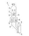
図1は、本発明の一実施形態に係る水素ガス貯蔵器10を示す。この水素貯蔵器10は、通常スチールあるいはアルミのボトルからなり、水素を貯蔵するための水素化物を収容する貯蔵キャニスター12を具備する。このキャニスター12は例えば
【特許文献10】
において開示されるような構成を有することが可能である。さらに、この水素貯蔵器10は、開口部14を有し、この開口部14から上記キャニスター12に水素が注入・排出される構成となっている。周知のように、開口部14は、密封弁16によって封じられ、ノブ15によって制御される。すなわちノブ15を回転させ封止位置におくことによって弁16は閉鎖され、この弁16は、キャニスター12が、同キャニスター12に貯蔵される水素を用いる燃料電池や、ニッケル水素電気機械セル、水素燃焼エンジンなど、他の接続デバイス(非図示)に接続されていない限り閉鎖されたままである。この弁16は、流体出入口18を有し、この流体出入口18が水素注入接続デバイスあるいは水素排出接続デバイスのいずれかに直接接続される場合に限り、同流体出入口18を介して水素が注入/排出される。この実施例では、上記弁16に流体連絡部材22を介して燃料計20が付設される。この燃料計20は、例えば以下に示されるいくつかの実施例の構成のうちの1つを適用することができる。 次に、図1及び図3を参照すると、図3は燃料計20の斜視図を示す。この燃料計20は、弁16との接続を実現するための流体連絡部材22を有する。すなわちこの流体連絡部材22は、キャニスター12に含まれる水素の圧力を示すために燃料計本体24と弁16とを流体連絡させる。燃料計本体24としては、標準的な水素圧力計を適用することが可能である。この燃料計/圧力計20はさらに前面32を有し、ここで表示部がキャニスター12内の水素の圧力を表示する。この表示部は、例えば図示されるような針30から構成されることができる。
【0012】
この燃料/圧力計20の前面32は、複数のスケール(尺度)を有するという点において他の圧力計と異なる。この詳細については以下において図2を参照しながら説明する。キャニスター12内に残存する水素の量を正確に測るためにはいくつかのスケールが必要である。水素化の分野では周知であるように、水素化物に貯蔵される水素ガスの圧力は、水素化物を用いない一般的な貯蔵器の場合のようにキャニスター12内の水素の圧力に直接対応するわけではない。さらに、水素化/脱水素化処理の特徴として、キャニスター12内の水素化物及び水素ガスの温度によってキャニスター12内の利用可能な水素ガスの量として示される量が異なる。
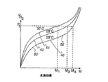
【0013】
次に、図2は、水素化物の水素容量Mを水素ガスのキャニスター12内の圧力PHSに対応させたグラフを示す。水素化物の特徴から、水素ガスを注入し出した初期の段階においては多くの水素が水素化物によって吸収される必要がある。水素ガスが水素化物によって吸収されていくにつれて、キャニスター12内の圧力が水素化物に吸収された水素とキャニスター12内を自由に浮遊する水素ガスとの間の平衡圧力に達する。キャニスター12内にさらに加圧水素を注入しつづけると、プラトー圧力として知られる圧力平衡曲線におけるある点に達するまで注入された水素は水素化物によって低速で吸収されていく。
【0014】
図2は、等温線40、42、及び44それぞれのプラトー圧力を示す。定温20℃での圧力を示す等温線40におけるプラトー圧力は点50付近から点52付近までの間にある。以下においてこの等温線40を例にとって、水素ガスの圧力が上昇するにつれてキャニスター12内にさらに加圧水素ガスが導入される圧力により吸収される水素の量が変化する様子を説明する。等温線40における点50と点52との間の等温線カーブの平坦部は水素化の分野においては一般的にプラトー圧力として知られ、このプラトー圧力によって本発明の実施例による効果が得られる。
【0015】
等温線40のプラトー圧力から、水素化物への水素ガスの吸収が最も速いのはプラトーにおける圧力の上昇が遅い間、つまり点50と点52の間であることがわかる。等温線40,42,44ではプラトー圧力において水素容量が大幅に増加する。よって燃料計をこのプラトー圧力帯付近における圧力の変化に機敏に反応するようにキャリブレーションすることによりキャニスター12内の水素化物に含まれる水素の容量を比較的正確に示すことができるようになる。
【0016】
図2に示す、異なる温度での水素化物による水素ガスの吸収は、温度をそれぞれ一定に保った中で平衡圧力の等温線を測定することによって得られる。一方キャニスター12内の水素ガスの圧力を一定値に保った中では、図2における一定圧力P1の例で示されるように、水素化物の水素容量Mは、温度が低くなるにつれて上昇する。つまり温度が等温線44(30℃)から等温線42(25℃)に低下すると、水素容量はM1からM2へと増加する、そして温度がさらに等温線40(20℃)へと低下した場合、水素容量はさらにM3に増加する。逆に一定の容量(例えばM1)においては、温度が高いほど平衡圧力が高い。これは圧力を一定に保って温度を上昇させた場合水素化物の温度が上昇し、水素化物が吸収していた水素が脱離し、その結果キャニスター12内の圧力が上昇するためである。さらに図2のグラフから明らかであるように、圧力計の各等温線40,42,44におけるプラトー圧力領域内の圧力P1直下の圧力に対する感性の向上及びキャリブレーションにより、残存容量がより正確に測ることが可能である(容量はより小さな圧力差分により変化するにもかかわらず)。
【0017】
しかし図2に示されるプラトー圧力は、この圧力が基準とする水素ガスの容量や特定温度において得られる平衡点については示唆しない。図2における一定圧力P1は、キャニスター12におけるそれぞれ異なる温度及びキャニスター12内の水素化物によって水素容量M1,M2,M3を示す。すなわち同一の圧力P1が、大小複数の水素化物内の水素量を示すこととなる(値P1がそれぞれの等温線40,42,44と交差する点の値がM1,M2,M3であることから)。
【0018】
したがってキャニスター12内の温度と燃料計20によって示される圧力との対応付けが必要となる。つまり圧力から水素容量Mを正確に示すためにキャニスター12内の温度を把握し、この温度に基づいて圧力を測定する。再び図3を参照すると、燃料計20の前面32はそれぞれ異なる温度に対応する複数のスケール34、36、及び38を有する。また前面32には温度反応ストリップ39が設けられ、この温度反応ストリップ39が変色によりシステム10における温度を示すことができる。例えばこのストリップ39が青、緑、赤へと変色することによりそれぞれ20℃、25℃、30℃と異なる温度を示すことができる。等温線40を例にとって説明すると、針30によって示される圧力P1は、温度20℃では、平衡圧力等温線がキャニスター12内の水素容量が容量M3であることを示し、圧力量のキャリブレーションによりスケール34は容量M3が、水素化物における水素が満容量に対応することを示す。また、ストリップ39が青であることにより、システム10内の温度が20℃であることがわかる。したがって燃料計20を読んでいる者は、温度20℃に対応するスケール、すなわちスケール34を参照して、キャニスター12に残存する水素の容量を測ればよい。
【0019】
また、ストリップ39が緑である場合、観測者は、25℃の等温線に対応するスケール36が現存の燃料の容量を示していることを認識し、この容量が半分であることを認識できる。また、ストリップ39が赤を示す場合、すなわち30℃に対応するスケールを参照するよう示唆する場合、観測者は30℃に対応スケール38を参照すべきであることを認識し、水素の容量が空に近いことを認識できる。
【0020】
図4は、本発明における又別の実施例に係る燃料計130の前面132を示す。同図においては、図3の燃料計20のように複数のスケールを設ける代わりに、任意の場面において1つのスケールのみが可視表示され、可視表示されるスケールが現在の温度に左右される構成となる。ここでは図3のストリップ39に用いられるような温度反応材料(コネチカット州スタンフォードのOmega Engineering社のものなど)からなるストリップが、本実施例による燃料計30の前面132の適正箇所に設けられる。燃料計130における各スケール134,136、138及び140はそれぞれの適正温度に応じて観測者にとって容易に視覚可能な状態で表示される。例えば、温度が20℃であった場合、青いスケール134が表示され、他のスケールは暗くされるかあるいは暗い色で示される。すなわち温度20℃に対するスケール134の温度反応性によりスケール134のみが明るく表示され、容易に視覚可能な状態となり、観測者は前面132において温度20℃に対応するスケール134のみを参照すべきであることを認識する。同様に、他のスケール136,138、及び140もそれぞれ対応する温度(例えば25℃、30℃、35℃)に反応して点灯するなどして明るく表示される。図4の前面132においてこれら他のスケールはそれぞれ点線で示されている。本実施例では、温度に対応して燃料計130の前面132における適正箇所のみが観測者にとって視覚可能な状態に表示されるため、確実に温度に対応する適正なスケールが参照されることとなる。
【0021】
また、本発明の別の仕様においては、図5に示されるように貯蔵キャニスター112が燃料計116の挿入部を構成する部分114を有する。図5に示されるように好ましくは、この燃料計116は、キャニスター12の底部に隣接して配置されるこの部分114に挿入される。また、この燃料計116はキャニスター112の側面に配置されることも可能である(非図示)。
【0022】
図6は上記実施例による燃料計116の詳細図である。燃料計116は、水素化合金120を保持するチャンバー122を構成する容器118を具備する。容器118は好ましくはスチールやその他温度の上昇により膨張しにくい剛性材料からなる。水素化合金120はチャンバー122内において同チャンバー122の長さ方向121にのみ膨張することができるように保持される。容器118は、この長さ方向に方向付けされ、水素化合金120を収容するチャンバー122から構成される。この水素化合金120は好ましくはキャニスター112に含まれる水素化物と同じ材料である。
【0023】
周知であるように、合金の水素化/脱水素化において、合金は水素の吸収/脱離に応じて伸縮する。例えば水素の吸収過程、つまり容量ゼロから容量フルになるまでの過程において合金の容量は10〜25%程度膨張しうる。この水素化合金は好ましくは長さ方向に延びる容器に収容される。この容器の形状により合金の膨張現象が拡大して見られる。したがって、特定の合金において水素容量が増加する際に、合金の水素吸収量によって膨張圧力の大小が決定される。
【0024】
水素化合金120が水素を吸収し、キャニスター112内の合金によって吸収される水素の量を示すためには、キャニスター112内の圧力と同等の圧力で水素を連絡提供する手段が備えられることが好ましい。よって図6に示されるように、キャニスター112とチャンバー122との間には、穴あきスクリーン(非図示)や開口部126などの連絡手段が設けられる。以下に示す実施例においては、図5の挿入部114の構成例を説明する。これらの実施例はキャニスター112内に残存する水素の容量を示すそれぞれの圧力反応手段により特徴付けられる。
【0025】
まず、図6に示されるチャンバー122を適用する構成における一実施例では、燃料計140がダイヤフラム150に接続されこれと直接協働する。この燃料計140は、同図に示されるような前面142に1つのスケールを有し、針144によりチャンバー122内の合金の膨張量を示す一般的な燃料計でよい。前面142は、例えばキャニスター112の壁に設けられる挿入部114の寸法・形状と一致する寸法・形状を有する。この実施例において、キャニスター112内に残存する水素の容量を計測するには、前面142における金属水素化物の膨張量を示す針144を参照すればよく、この金属水素化物の膨張量はおおよそ残存水素の容量に対応する。
【0026】
ここで前面142が1つのスケールを適用するのは、収容される金属水素化物の物理的容量の拡大は、この水素化物に含まれる水素の量によって大きく左右されるのであって、水素化物の温度によってはさほど左右されないからである。つまり水素化物の容量拡大の要因として水素吸収量の影響が重要であるため、温度による拡大効果は無視することができる。しかし、温度の上昇による金属水素化物の容量拡大を考慮するより的確な測定が望まれる場合は、図3、図4における前面32,132と同様に前面142にもキャリブレーション・スケールを設けることが可能である。
【0027】
容器118のダイヤフラム150(図6参照)は、キャニスター112の開口部を密封し、流体あるいは気体を遮断する。このダイヤフラム150は直接的あるいは間接的に方向121に拡張可能な水素化物120と接触する。水素化物120の方向121以外への拡張は容器118の剛性側壁によって制約されている。よって水素化物120を的確に詰めることによりこの拡張はすべて方向121によって示される長さ方向において反映される。ここで水力動作の原理を適用して、ダイヤフラム150によって覆われる開口152の小さな口径が、水素化物120の10〜25%容量拡大をダイヤフラム150に作用する強力縦長衝動圧力に変換する。このダイヤフラム150はポスト156によって燃料計140に接続され、このポスト156の縦長変位が針144を金属水素化物120における水素容量の的確に示す位置へと導く。
【0028】
金属水素化物120の水素吸収特性をキャニスター112内の金属水素化物の水素吸収特性と一致させるために、好ましくは金属水素化物120としてはキャニスター112内の金属水素化物と同様のものを適用する。つまり、水素化物120をうまくパッキングし、流体連絡管126を介して導入される水素ガスを効果的に分散することによりキャニスター112内と同様の水素吸収が実現され、これにより同様の水素化物容量の拡大が実現される。こうして比較的正確なキャニスター112内の水素の容量の測定が可能となる。
【0029】
また、チャンバー122内にはキャニスター112内の水素化物よりも拡張しやすい合金材料を用いることも可能である。つまり、キャニスター12内に収容される一般水素化物よりも膨張する金属水素化物合金を使用することによりチャンバー122における水素化物の容量のより大幅な相対変動が実現される。よって前面142のスケールをより正確に読み取ることが可能となる。2種類の水素化物が用いられた場合、それぞれの水素化物のプラトー圧力が対応付けられていることを十分確認したうえでスケールのキャリブレーションを行う必要がある。
【0030】
次に図7を参照してまた別の実施例に係る容器218の構成を説明する。図7に示される容器218は、図5のキャニスター112の部分114に挿入されうるような形状及び寸法を有し、剛性壁部219、開口222、金属水素化物220から構成される。金属水素化物220は、キャニスター112内の水素化物と同様の材料であってよい。またこの容器218の剛性壁部219が硬質であると同時に水素ガスを通す多孔質の材料からなる場合は、流体連絡管が不要となる。これは上述の実施例においても同様である。このような構成により、チャンバー218においてより効率的で均等な水素の分布が得られ、水素ガスが金属水素化物220によってより均等に吸収されうる。これにより連続的膨張特性が実現される。
【0031】
なお、本発明の燃料計における表示手段は、上述のものに限定されるものではない。例えば、ダイヤフラムが電子圧力インジケータなど必要な情報を提供できる指示手段と結合されてもよい。図7において容器218は、圧力反応プラスチックからなるダイヤフラム240を有し、この圧力反応プラスチックのダイヤフラム240は例えば容器218内の圧力量によって青から赤へと変色する。この圧力反応プラスチックのダイヤフラム240は、金属水素化物220に対向してガラスカバー242及びねじ込みベゼル250により固定されうる。このねじ込みベゼル250は、定位置にねじ込まれることによりガラスカバー242に突き当たり、開口222を密封し、水素ガスがキャニスター112外へ流出することを防ぐ。
【0032】
圧力反応プラスチックのダイヤフラム240は、チャンバー220内の水素化物220によって及ぼされる長手方向の圧力量によって変色する特性を有する。例えば、このダイヤフラムは、多くの水素が水素化物から排出され、水素化物の膨張が見られない状態である場合は青色を示すよう設定されうる。また、水素の容量がおおよそ半分(1/2)である場合、つまり図2におけるプラトー圧力付近の圧力が検出された場合は、緑色を示すよう設定されうる。また、水素化物に水素がフルに吸収されていてこれ以上水素を吸収することができない状態である場合、赤色を示すように設定しうる。なお、ダイヤフラム240に圧力を及ぼす水素化物が水素化物220によって及ぼされる長手方向の圧力によって影響されることはいうまでもない。また容量拡大圧力はチャンバー222内の水素ガスによって及ぼされるガス圧力よりも大きいことが配慮される。したがってベゼル250のねじ調整などでキャニスター112内の水素化物の水素容量に対するダイヤフラム240の変色規則をさらに校正するための手段が必要な場合もありうる。
【0033】
次に図8を参照して、本発明によるまた別の実施例に係る燃料計310の構成を説明する。この燃料計310はキャニスター312及びポート314を有し、このポート314を介してリード線316,318はキャニスター312へと延びる。リード線316及び318はそれぞれキャニスター312内の状態を検知する状態センサーに接続される。例えばリード線316は、キャニスター312内に配置される圧力変換器(非図示)に接続され、この圧力変換器は、キャニスター312内の水素ガス圧力を検知するか、より好ましくはキャニスター312内に配置される圧電変換器320が検知する圧力を検知する。この圧力変換器は直接水素ガス圧力を読み取るか、あるいは容器218(図6)同様に容器(非図示)を有し、その中に収容される水素化物の及ぼす圧力に反応する構成にすることも可能である。いずれの場合においても、変換器320は、圧力値に対応する電気信号を生成し、これをプログラム可能論理回路(PLC)あるいはマイクロプロセッサ330に伝送する。このマイクラオプロセッサ330は好ましくはキャニスター312の外側に配置され、上記信号は線326を介して伝送される。
【0034】
リード線318は、キャニスター312内に配置され、例えば熱電対あるいは抵抗温度計検出器(RTD)などから構成される温度センサー322に接続される。この温度センサー322はリード線318を介して信号を生成し、この信号は線328を介して中央プロセッサ330に伝送される。
【0035】
プロセッサ330はセンサー320,322から伝送された信号を受信し、これらを所定のアルゴリズムを用いて電子操作し、キャニスター312内の水素容量の値を演算する。この演算値はアナログ値あるいはより好ましくはデジタル値であり、プロセッサ330に接続されるディスプレイ332によって表示されうる。また、プロセッサ330の代わり又はこれと共にセンサー320及び322によって検知される圧力及び温度の値をそれぞれ独自に検証し、水素容量ディスプレイ332が適正なデータを示していることを確認することができる。また、ユーザーが例えば参照テーブルなどを用いてディスプレイ336,338に示されるリード線316,318それぞれからのデータに基づいて水素容量を独自に求めることもできる。
【0036】
また、圧力及び温度の値自体を例えばディスプレイ336、338に表示することも可能である。つまりディスプレイ336にはキャニスター312内の水素ガス圧力あるいはより好ましくはキャニスター312内の電圧変換器320によって検知される電圧力が表示され、ディスプレイ338にはキャニスター312内の温度が表示されることも可能である。リード線316,318はセンサーポート314に常に取り付けられるか、あるいはこれらリード線は脱着可能に設けられ、キャニスター312の状態の情報が求められる際にポート314に取り付けられる携帯マイクロプロセッサ330を有す構成とすることが可能である。
【0037】
図9及び図10は本発明の更なる実施例を示す。本実施例による水素貯蔵器410は、貯蔵キャにスター412を有し、この貯蔵キャニスター412の側面には挿入部414は設けられる。なお、この挿入部414の配設位置はキャニスター412の側面に限らず例えば図5のように底面に配置するかあるいは弁416に配置することも可能である。挿入部414は、キャニスター412内の抵抗部材420との電気的接続を実現するための絶縁リード線418のためのポートを有する。この詳細については後ほど図10を参照して説明する。
【0038】
キャニスター412の外部においてリード線418は電気抵抗を計測するデバイス440に電気的に接続される。このデバイス440は例えば抵抗あるいは水素容量を示すディスプレイ442を具備しうる。この水素容量は、デバイス440内の論理制御回路444において校正アルゴリズムを用いてキャニスター412内からリード線418を介して受信された電気抵抗信号から計算されうる。またリード線418は、形態可能な独立抵抗計測デバイス440に適用することも可能である。この場合リード線418は例えば電気コンセントの構造に似た挿入部414内に配置される電気挿入口(非図示)に一時的に挿入される。この構成により、ユーザーは計測デバイス440を携帯し、リード線418を挿入し、水素容量を計測した後、リード線418を挿入口から抜いて、他の貯蔵器410をモニターすることができる。
【0039】
本本実施例による貯蔵器410は、水素化物のさらに別の特性である抵抗の増加と水素容量の増加との相関関係に基づいて動作する。この抵抗と容量との直接的相関関係は決定的には確立されていないものの、適切な校正を行えばこの相関関係は水素容量を正確に計測するのには十分な滑性を有する。すなわち抵抗の増加に対する水素化物の容量の増加が既知の相関関係に基づくため、水素化物の局部電気抵抗を空水素容量の値を得ることが可能である。本発明において適用対象とされている金属水素化物においての抵抗は、水素化物が水素を含まない場合の値と水素化物の水素含有量が飽和点付近にある場合の値との間で200%もの変動がありうる。
【0040】
図10は、図9における抵抗部材420の断面図を示す。抵抗部材420はキャニスター412内に配置され、挿入部414から挿入される電気リード線418を介して電気信号を外部へ伝送する。電気リード線418はそれぞれ内部チャンバー424内に配置される端子422によって終端される。この内部チャンバー424には水素化物430が密接に詰められていて、好ましくは円柱を形成する円柱側壁部426及び端壁部428を有し、端子422は互いに離れた位置にあって、両端にある端壁部428のそれぞれに隣接して配置される。なお、この内部チャンバー424の形状は円柱形とどまらず、例えば六角柱や四角柱など他の形状にすることも可能である。
【0041】
チャンバー424の壁部426,428は水素ガスを透過する電気絶縁材料からなり、例えば、デラウェア州ウィルミントンに本拠地を置くE.I.du Pont de Nemours社製のテフロン(登録商標)を用いることが可能である。壁部426,428を水素透過性材料で構成することにより、チャンバー424内の水素化物430が自由且つ均等に水素を吸収・脱利することが可能になる。また端子422巻の距離を所定距離に設定することにより、所定サイズのチャンバー424において端子間における所望の抵抗が得られる。
【0042】
チャンバー424には粉末状の水素化物430が所定密度で詰められていて、これによって水素化物430の水素容量によって変化する抵抗が所定の抵抗レベルに設定される。また、貯蔵器410における水素化物の水素容量を統一させるために、この水素化物430は好ましくはキャニスター412に含まれる水素化物と同様のものである。これによりキャニスター412内の水素化物の水素容量を正確に読み取ることが可能になる。
【0043】
動作時には、実質的にキャニスター412内の水素化物の抵抗と同等である端子422間の抵抗を示す信号が抵抗部材420から伝送される。この信号は抵抗計測デバイス440に送られ、ここで論理制御回路44においてアクセスされる校正アルゴリズムを用いて信号が分析され、キャニスター412内の金属水素化物の水素容量が測定される。この実施例では、抵抗計測デバイス440が水素を吸収することができるため、デバイス440によって占有される空間が無駄にされず水素貯蔵にも活用されうるという利点がある。
【0044】
そのほかにも同業者は本願において開示される範囲に基づき多くの変形例を容易に着想することが可能であろう。例えば、本願の実施例で開示されるセンサー及び/又は色指示部の組み合わせを変更することが可能であり、また本願の実施例では詳細に説明されない他の状態を検知するセンサーを適用することも可能である。例えば、重量センサーなどをキャニスターの内部あるいは外部に配置することも可能である。重量センサーが外部に配置された場合は、ボトルや弁の風袋重量を用いて水素容量の別あるいは補足的な計測値が提供されうる。水素化物などの物質のホール効果計は、水素容量の増加に伴いその物質の電磁特性を変更することが知られている。したがって、磁場を誘発し、水素化物の電圧などの電気特性を検知するセンサーなどが容器に収容される水素化物の水素容量の計測に用いられることも考えられる。なお、正確な計測を実現するには、物質の既知の特性に基づく適正な校正が必要となる。
【0045】
なお、本発明は特許請求の範囲によってのみ限定されうるのであって、上記の実施例は本発明の具体的適用例を示しているに過ぎない。
【図面の簡単な説明】
【0046】
【図1】本発明の一実施形態に係る水素貯蔵器の正面図である。
【図2】異なる温度の中での水素の容量と圧力の関係を示すグラフである。
【図3】本発明の第1実施形態に係る燃料計の斜視図である。
【図4】本発明の第2実施形態に係る燃料計の表示部の図である。
【図5】本発明の又異なる実施形態を示す図である。
【図6】図5に示される水素貯蔵容器の表示部の詳細図である。
【図7】図5の実施形態の変形例を示す図である。
【図8】本発明の又異なる実施形態に係る燃料計システムを示す図である。
【図9】本発明の又異なる実施形態を示す図である。
【図10】図9に示される水素貯蔵容器の断面図である。【Technical field】
[0001]
The present invention relates generally to hydrogen reservoirs, and more particularly to reservoirs that use metal hydrides to store large amounts of hydrogen at low pressure.
[Background]
[0002]
In contrast to the current situation in which hydrogen is being used in many commercial and commercial equipment, the conventional hydrogen storage method for storing hydrogen as a pressure gas is known to have undesirable risks. ing. When storing hydrogen as a gas, it is typically performed at high pressure (eg, 2,000 psi) in a large iron cylinder.
[0003]
Hydrogen can also be stored as a liquid, which is typically done at a low temperature in an insulated container. Here, it is necessary to keep the temperature low so that the hydrogen liquid does not evaporate or boil, and this requires energy. Thus, low temperature hydrogen generation and storage is inefficient due to the need to maintain the reservoir at cryogenic temperatures.
[0004]
Recently, a technique for storing hydrogen in a metal compound known as a hydride has attracted attention. Metal hydrides can store large amounts of hydrogen in small amounts at low pressure. Low pressure storage of hydrogen in a hydride containing container is relatively safe, and the hydrogen container used in this case will have a significantly different configuration than the container storing hydrogen gas. For example, in
[0005]
In addition, the assignee of the present invention sells a hydrogen storage container under the name “Ergeneics ST-Series hydrogen storage unit”, and the hydrogen store is HY-STOR (registered) which is a hydride produced by the assignee. Trademark 208 hydride alloy or the like is used. Details of the reservoir and hydride alloy can be found on the assignee's homepage www. ergenics. com. Further, techniques for storing hydrogen using a solid material that can be hydrogenated are disclosed in Patent Document 4, Patent Document 5, Patent Document 6, Patent Document 7, Patent Document 8, Patent Document 9, and the like.
[0006]
Such metal hydride reservoirs can be applied to various industrial / laboratory equipment and environments. Therefore, in order to cope with various applications, a storage system that can accurately provide various capacities of hydrogen to users is required. For example, the small reservoir as described above is generally used as a hydrogen source in laboratory experiments. On the other hand, since a larger amount of hydrogen is required in a vehicle transportation system and a practical device, a larger reservoir is used. Regardless of the size and capacity of the reservoir, there is a need for a storage system that can quickly and easily use hydrogen gas and that can function properly and accurately under various environmental conditions.
[0007]
In the hydrogen storage system, the user can measure the amount of hydrogen gas in the hydride container as necessary, but it is difficult to measure the amount of available hydrogen gas. Although accurate measurement is desired, it is generally desired that measurement accuracy be in the range of 15-30%.
[0008]
Particularly, in the conventional metal hydrogen storage system, it is difficult to accurately measure the amount of available hydrogen gas because of its structure and operation. In a gas container that stores hydrogen in a gas state, it is possible to accurately estimate the available hydrogen gas from the equation of state (PV = nRT) of the ideal gas. This is because when the temperature is kept constant, the amount of hydrogen is proportional to the pressure. That is, in a hydrogen storage system that stores hydrogen in a gas container, the capacity V and the temperature T are substantially constant, and the amount n of hydrogen gas is discharged from the system. Here, assuming that the amount of hydrogen gas taken out from the container and used (amount of decrease) is the amount of hydrogen n, a pressure decrease amount P is obtained in proportion to this. Thus, by accurately reading the pressure P here, it is possible to estimate the amount of available hydrogen in the container fairly accurately.
[0009]
However, in the case of a storage container using hydride, the assumption is made that the amount of available hydrogen remaining in the container is proportional to the pressure P because hydrogen gas is introduced into the lattice structure of the metal hydride. I can't. Therefore, in order to measure hydrogen in the container, it is necessary to provide a relatively high-precision measuring instrument such as a fuel gauge in a general internal combustion vehicle.
[Patent Document 1]
US Pat. No. 5,250,368
[Patent Document 2]
US Patent No. 5,532,074
[Patent Document 3]
US Patent No. 5,623,987
[Patent Document 4]
US Patent No. 3,508,514
[Patent Document 5]
US Patent No. 3,516,263
[Patent Document 6]
US Patent No. 4,036,944
[Patent Document 7]
US Patent No. 5,518,528
[Patent Document 8]
US Patent No. 5,697,221
[Patent Document 9]
US Patent No. 5,906,792
[Patent Document 10]
US Patent No. 4,396,114
DISCLOSURE OF THE INVENTION
[0010]
Therefore, the present application provides a hydrogen gas storage container having a canister for storing a metal hydride that has at least one opening for injecting and discharging gas and that can absorb and desorb hydrogen gas, and the hydride. A hydrogen gas storage container is proposed, which is composed of a fuel gauge for measuring the capacity of the remaining hydrogen. Furthermore, in order to distribute hydrogen throughout the hydride, a porous matrix can be placed on the metal hydride to achieve efficient hydrogen distribution in the hydride. Furthermore, the fuel gauge can have a subassembly for measuring the capacity of hydrogen and can be based on various principles. For example, the fuel gauge may include a pressure gauge that provides a plateau pressure indicative of hydrogen capacity, a piezoelectric sensor that provides a pressure differential indicative of hydrogen capacity in cooperation with a rigid chamber closely packed with hydride, and a hydride. It is possible to apply a resistance sensor that cooperates with the clogged chamber to provide a resistance difference indicative of hydrogen capacity.
BEST MODE FOR CARRYING OUT THE INVENTION
[0011]
FIG. 1 shows a hydrogen gas reservoir 10 according to an embodiment of the present invention. The hydrogen storage device 10 is usually made of a steel or aluminum bottle and includes a storage canister 12 that contains a hydride for storing hydrogen. This canister 12 is for example
[Patent Document 10]
It is possible to have a configuration as disclosed in. Further, the hydrogen storage device 10 has an opening 14, and hydrogen is injected into and discharged from the canister 12 through the opening 14. As is well known, the opening 14 is sealed by a sealing valve 16 and controlled by a knob 15. That is, the valve 16 is closed by rotating the knob 15 to the sealing position, and the valve 16 is configured so that the canister 12 is a fuel cell using hydrogen stored in the canister 12, a nickel hydrogen electromechanical cell, hydrogen combustion. It remains closed unless connected to another connection device (not shown), such as an engine. The valve 16 has a fluid inlet / outlet 18, and hydrogen is injected / exhausted through the fluid inlet / outlet 18 only when the fluid inlet / outlet 18 is directly connected to either a hydrogen inlet / outlet connecting device. Is done. In this embodiment, a fuel gauge 20 is attached to the valve 16 via a fluid communication member 22. For example, one of several configurations shown below can be applied to the fuel gauge 20. 1 and 3, FIG. 3 shows a perspective view of the fuel gauge 20. The fuel gauge 20 has a fluid communication member 22 for realizing connection with the valve 16. That is, the fluid communication member 22 fluidly communicates the fuel gauge body 24 and the valve 16 to indicate the pressure of hydrogen contained in the canister 12. As the fuel gauge main body 24, a standard hydrogen pressure gauge can be applied. The fuel gauge / pressure gauge 20 further has a front surface 32, where the display unit displays the pressure of hydrogen in the canister 12. This display part can be comprised from the needle | hook 30 as shown, for example.
[0012]
The front face 32 of the fuel / pressure gauge 20 differs from other pressure gauges in that it has a plurality of scales. This will be described in detail below with reference to FIG. Several scales are required to accurately measure the amount of hydrogen remaining in the canister 12. As is well known in the hydrogenation field, the pressure of the hydrogen gas stored in the hydride directly corresponds to the pressure of the hydrogen in the canister 12 as is the case with typical reservoirs that do not use hydride. is not. Further, as a characteristic of the hydrogenation / dehydrogenation treatment, the amount indicated as the amount of available hydrogen gas in the canister 12 varies depending on the temperature of the hydride and hydrogen gas in the canister 12.
[0013]
Next, FIG. 2 shows the hydrogen capacity M of the hydride as the pressure P in the hydrogen gas canister 12. HS A graph corresponding to is shown. Due to the characteristics of the hydride, a lot of hydrogen needs to be absorbed by the hydride at the initial stage when the hydrogen gas is injected. As hydrogen gas is absorbed by the hydride, the pressure in the canister 12 reaches an equilibrium pressure between the hydrogen absorbed in the hydride and the hydrogen gas freely floating in the canister 12. As pressurized hydrogen is further injected into the canister 12, the injected hydrogen is slowly absorbed by the hydride until a point in the pressure equilibrium curve known as the plateau pressure is reached.
[0014]
FIG. 2 shows the plateau pressure for each of the
[0015]
From the plateau pressure of the isotherm 40, it can be seen that the fastest absorption of hydrogen gas into the hydride occurs during the slow rise in pressure at the plateau, that is, between
[0016]
The absorption of hydrogen gas by hydrides at different temperatures shown in FIG. 2 is obtained by measuring the isotherm of the equilibrium pressure while keeping the temperature constant. On the other hand, while maintaining the hydrogen gas pressure in the canister 12 at a constant value, the constant pressure P in FIG. 1 As shown in the example, the hydrogen capacity M of the hydride increases as the temperature decreases. That is, when the temperature drops from the isotherm 44 (30 ° C.) to the isotherm 42 (25 ° C.), the hydrogen capacity is M 1 To M 2 If the temperature increases to and further decreases to the isotherm 40 (20 ° C.), the hydrogen capacity further increases to M 3 To increase. Conversely, a certain capacity (for example, M 1 ), The higher the temperature, the higher the equilibrium pressure. This is because when the pressure is kept constant and the temperature is raised, the temperature of the hydride rises, the hydrogen absorbed by the hydride is desorbed, and as a result, the pressure in the canister 12 rises. Further, as is apparent from the graph of FIG. 2, the pressure P in the plateau pressure region in each of the
[0017]
However, the plateau pressure shown in FIG. 2 does not suggest the equilibrium point obtained at the specified hydrogen gas capacity or at a specific temperature. Constant pressure P in FIG. 1 , The hydrogen capacity M due to the different temperatures in the canister 12 and hydrides in the canister 12. 1 , M 2 , M 3 Indicates. That is, the same pressure P 1 Indicates the amount of hydrogen in a plurality of hydrides of large and small (value P 1 Is the value of the point where each crosses the
[0018]
Therefore, it is necessary to associate the temperature in the canister 12 with the pressure indicated by the fuel gauge 20. That is, in order to accurately indicate the hydrogen capacity M from the pressure, the temperature in the canister 12 is grasped, and the pressure is measured based on this temperature. Referring again to FIG. 3, the front face 32 of the fuel gauge 20 has a plurality of scales 34, 36, and 38, each corresponding to a different temperature. Also, a temperature reaction strip 39 is provided on the front surface 32, and the temperature reaction strip 39 can indicate the temperature in the system 10 by changing color. For example, when the strip 39 changes color to blue, green, and red, temperatures different from 20 ° C., 25 ° C., and 30 ° C. can be shown, respectively. Taking the isotherm 40 as an example, the pressure P indicated by the needle 30 1 At 20 ° C., the equilibrium pressure isotherm indicates that the hydrogen capacity in the canister 12 is the capacity M. 3 The scale 34 has the capacity M by the calibration of the pressure amount. 3 Indicates that the hydrogen in the hydride corresponds to full capacity. It can also be seen that the temperature in the system 10 is 20 ° C. because the strip 39 is blue. Accordingly, a person reading the fuel gauge 20 may measure the capacity of hydrogen remaining in the canister 12 with reference to the scale corresponding to the temperature of 20 ° C., that is, the scale 34.
[0019]
If the strip 39 is green, the observer can recognize that the scale 36 corresponding to the 25 ° C. isotherm indicates the capacity of the existing fuel and recognize that this capacity is half. Also, if the strip 39 shows red, i.e. suggests referring to a scale corresponding to 30 ° C., the observer recognizes that he should refer to the corresponding scale 38 at 30 ° C. and the capacity of hydrogen is empty. It can be recognized that it is close to.
[0020]
FIG. 4 shows a front surface 132 of a fuel gauge 130 according to another embodiment of the present invention. In the same figure, instead of providing a plurality of scales as in the fuel gauge 20 of FIG. 3, only one scale is visible in an arbitrary scene, and the visible scale depends on the current temperature. Become. Here, a strip made of a temperature-responsive material (such as that of Omega Engineering, Stamford, Conn.) As used for the strip 39 of FIG. 3 is provided at an appropriate location on the front surface 132 of the fuel gauge 30 according to this embodiment. The scales 134, 136, 138, and 140 in the fuel gauge 130 are displayed in a state that is easily visible to the observer according to their appropriate temperatures. For example, if the temperature is 20 ° C., a blue scale 134 is displayed and the other scales are darkened or shown in a dark color. That is, only the scale 134 is brightly displayed due to the temperature responsiveness of the scale 134 to the temperature of 20 ° C., and is easily visible, and the observer should refer only to the scale 134 corresponding to the temperature of 20 ° C. on the front surface 132. Recognize Similarly, the other scales 136, 138, and 140 are also displayed brightly by being turned on in response to corresponding temperatures (for example, 25 ° C., 30 ° C., and 35 ° C.). Each of these other scales are indicated by dotted lines on the front surface 132 of FIG. In the present embodiment, only an appropriate location on the front surface 132 of the fuel gauge 130 corresponding to the temperature is displayed in a state visible to the observer, so that an appropriate scale corresponding to the temperature is reliably referred to. .
[0021]
Further, in another specification of the present invention, as shown in FIG. 5, the storage canister 112 has a portion 114 that constitutes an insertion portion of the fuel gauge 116. Preferably, as shown in FIG. 5, the fuel gauge 116 is inserted into this portion 114 that is located adjacent to the bottom of the canister 12. The fuel gauge 116 can also be disposed on the side surface of the canister 112 (not shown).
[0022]
FIG. 6 is a detailed view of the fuel gauge 116 according to the above embodiment. The fuel gauge 116 includes a container 118 constituting a chamber 122 that holds the hydrogenated alloy 120. The container 118 is preferably made of steel or other rigid material that is difficult to expand as the temperature increases. The hydrogenated alloy 120 is held in the chamber 122 so that it can expand only in the longitudinal direction 121 of the chamber 122. The container 118 is composed of a chamber 122 that is oriented in this length direction and contains the hydrogenated alloy 120. This hydride alloy 120 is preferably the same material as the hydride contained in the canister 112.
[0023]
As is well known, in hydrogenation / dehydrogenation of alloys, the alloys expand and contract in response to hydrogen absorption / desorption. For example, in the process of absorbing hydrogen, that is, in the process from zero capacity to full capacity, the capacity of the alloy can expand by about 10 to 25%. The hydrogenated alloy is preferably contained in a container extending in the longitudinal direction. The expansion phenomenon of the alloy can be seen enlarged due to the shape of the container. Therefore, when the hydrogen capacity increases in a specific alloy, the magnitude of the expansion pressure is determined by the hydrogen absorption amount of the alloy.
[0024]
In order for hydrogenated alloy 120 to absorb hydrogen and indicate the amount of hydrogen absorbed by the alloy in canister 112, it is preferred that a means for communicating and providing hydrogen at a pressure equivalent to the pressure in canister 112 is provided. . Therefore, as shown in FIG. 6, communication means such as a perforated screen (not shown) and an opening 126 are provided between the canister 112 and the chamber 122. In the following embodiment, a configuration example of the insertion unit 114 in FIG. 5 will be described. These embodiments are characterized by respective pressure responsive means that indicate the volume of hydrogen remaining in the canister 112.
[0025]
First, in an embodiment in which the chamber 122 shown in FIG. 6 is applied, the fuel gauge 140 is connected to the diaphragm 150 and directly cooperates therewith. The fuel gauge 140 may be a general fuel gauge having one scale on the front surface 142 as shown in the figure and indicating the amount of expansion of the alloy in the chamber 122 by the needle 144. The front surface 142 has a size / shape that matches the size / shape of the insertion portion 114 provided on the wall of the canister 112, for example. In this embodiment, the amount of hydrogen remaining in the canister 112 can be measured by referring to the needle 144 indicating the amount of expansion of the metal hydride on the front surface 142. The amount of expansion of the metal hydride is approximately the amount of residual hydrogen. Corresponds to the capacity of.
[0026]
Here, the front surface 142 applies one scale because the expansion of the physical capacity of the metal hydride accommodated depends greatly on the amount of hydrogen contained in the hydride, and the temperature of the hydride. It is because it is not influenced so much depending on. In other words, since the influence of the hydrogen absorption amount is important as a factor for expanding the capacity of the hydride, the expansion effect due to temperature can be ignored. However, if more accurate measurement is desired considering the increase in metal hydride capacity due to temperature rise, a calibration scale may be provided on the front surface 142 as well as the front surfaces 32 and 132 in FIGS. Is possible.
[0027]
A diaphragm 150 (see FIG. 6) of the container 118 seals the opening of the canister 112 and blocks fluid or gas. The diaphragm 150 is in contact with the hydride 120 that can expand directly or indirectly in the direction 121. Expansion of hydride 120 in directions other than direction 121 is constrained by the rigid sidewalls of vessel 118. Thus, by properly packing the hydride 120, all this expansion is reflected in the length direction indicated by the direction 121. Here, applying the principle of hydraulic operation, the small diameter of the opening 152 covered by the diaphragm 150 converts the 10-25% capacity expansion of the hydride 120 into a strong longitudinal impulse pressure acting on the diaphragm 150. The diaphragm 150 is connected to the fuel gauge 140 by a post 156, and the longitudinal displacement of the post 156 leads the needle 144 to a position that accurately indicates the hydrogen capacity in the metal hydride 120.
[0028]
In order to match the hydrogen absorption characteristics of the metal hydride 120 with the hydrogen absorption characteristics of the metal hydride in the canister 112, the same metal hydride 120 as the metal hydride in the canister 112 is preferably used. That is, the hydrogen absorption similar to that in the canister 112 is realized by packing the hydride 120 well and effectively dispersing the hydrogen gas introduced through the fluid communication pipe 126, thereby achieving the same hydride capacity. Expansion is realized. In this way, the hydrogen capacity in the canister 112 can be measured relatively accurately.
[0029]
It is also possible to use an alloy material that is easier to expand than the hydride in the canister 112 in the chamber 122. That is, by using a metal hydride alloy that expands more than the general hydride housed in the canister 12, a greater relative variation in the hydride volume in the chamber 122 is achieved. Therefore, the scale of the front surface 142 can be read more accurately. When two types of hydrides are used, it is necessary to calibrate the scale after sufficiently confirming that the plateau pressure of each hydride is associated.
[0030]
Next, a configuration of a container 218 according to another embodiment will be described with reference to FIG. The container 218 shown in FIG. 7 has a shape and size that can be inserted into the portion 114 of the canister 112 of FIG. 5, and is composed of a rigid wall 219, an opening 222, and a metal hydride 220. The metal hydride 220 may be the same material as the hydride in the canister 112. Further, when the rigid wall 219 of the container 218 is hard and is made of a porous material that allows hydrogen gas to pass therethrough, a fluid communication pipe is not necessary. The same applies to the above-described embodiments. With such a configuration, a more efficient and uniform hydrogen distribution can be obtained in the chamber 218, and the hydrogen gas can be more evenly absorbed by the metal hydride 220. This achieves continuous expansion characteristics.
[0031]
The display means in the fuel gauge of the present invention is not limited to the above-described one. For example, the diaphragm may be combined with indicating means that can provide the necessary information, such as an electronic pressure indicator. In FIG. 7, the container 218 has a diaphragm 240 made of a pressure-responsive plastic, and the pressure-responsive plastic diaphragm 240 changes from blue to red, for example, depending on the amount of pressure in the container 218. The pressure responsive plastic diaphragm 240 may be secured to the metal hydride 220 by a glass cover 242 and a screwed bezel 250. The screwed bezel 250 hits the glass cover 242 by being screwed into place, seals the opening 222 and prevents hydrogen gas from flowing out of the canister 112.
[0032]
The pressure responsive plastic diaphragm 240 has the property of changing color with the amount of longitudinal pressure exerted by the hydride 220 in the chamber 220. For example, the diaphragm can be set to show a blue color when a lot of hydrogen is exhausted from the hydride and no hydride expansion is seen. Further, when the hydrogen capacity is approximately half (1/2), that is, when a pressure near the plateau pressure in FIG. 2 is detected, it can be set to indicate green. Moreover, when hydrogen is fully absorbed in the hydride and cannot absorb hydrogen any more, it can be set to show red. Of course, the hydride that exerts pressure on the diaphragm 240 is affected by the longitudinal pressure exerted by the hydride 220. It is also considered that the capacity expansion pressure is larger than the gas pressure exerted by the hydrogen gas in the chamber 222. Accordingly, a means for further calibrating the discoloration rule of the diaphragm 240 with respect to the hydrogen capacity of the hydride in the canister 112 by adjusting the screw of the bezel 250 may be necessary.
[0033]
Next, the configuration of a fuel gauge 310 according to another embodiment of the present invention will be described with reference to FIG. The fuel gauge 310 includes a
[0034]
The
[0035]
The
[0036]
Further, the pressure and temperature values themselves can be displayed on the
[0037]
9 and 10 show a further embodiment of the present invention. The hydrogen storage device 410 according to the present embodiment has a star 412 in the storage canister, and an insertion portion 414 is provided on a side surface of the storage canister 412. In addition, the arrangement position of the insertion portion 414 is not limited to the side surface of the canister 412, and may be arranged on the bottom surface as shown in FIG. 5 or on the valve 416. The insert 414 has a port for an insulated lead 418 to achieve electrical connection with the resistance member 420 in the canister 412. Details of this will be described later with reference to FIG.
[0038]
Outside the canister 412, the lead wire 418 is electrically connected to a device 440 that measures electrical resistance. The device 440 may include a display 442 that indicates, for example, resistance or hydrogen capacity. This hydrogen capacity may be calculated from the electrical resistance signal received via lead 418 from within canister 412 using a calibration algorithm at logic control circuit 444 within device 440. The lead wire 418 can also be applied to a formable independent resistance measuring device 440. In this case, the lead wire 418 is temporarily inserted into an electrical insertion port (not shown) disposed in an insertion portion 414 similar to the structure of an electrical outlet, for example. With this configuration, the user can carry the measuring device 440, insert the lead wire 418, measure the hydrogen capacity, and then remove the lead wire 418 from the insertion port to monitor the other reservoir 410.
[0039]
The reservoir 410 according to the present embodiment operates based on a correlation between an increase in resistance, which is another characteristic of hydride, and an increase in hydrogen capacity. Although this direct correlation between resistance and capacity has not been definitively established, this correlation has sufficient lubricity to accurately measure hydrogen capacity when properly calibrated. That is, since the increase in the hydride capacity with respect to the increase in resistance is based on a known correlation, it is possible to obtain the value of the local hydrogen resistance of the hydride for the air hydrogen capacity. The resistance of the metal hydride that is the object of application in the present invention is 200% between the value when the hydride does not contain hydrogen and the value when the hydrogen content of the hydride is near the saturation point. There can be fluctuations.
[0040]
FIG. 10 is a sectional view of the resistance member 420 in FIG. The resistance member 420 is disposed in the canister 412 and transmits an electric signal to the outside through an electric lead 418 inserted from the insertion portion 414. Each electrical lead 418 is terminated by a terminal 422 disposed within the internal chamber 424. The internal chamber 424 is closely packed with a hydride 430 and preferably has a cylindrical side wall portion 426 and an end wall portion 428 forming a circular column, and the terminals 422 are at a distance from each other and at both ends. Arranged adjacent to each of the end wall portions 428. Note that the shape of the internal chamber 424 is not limited to a cylindrical shape, and may be other shapes such as a hexagonal column and a square column.
[0041]
The walls 426, 428 of the chamber 424 are made of an electrically insulating material that is permeable to hydrogen gas, for example E.C. based in Wilmington, Delaware. I. It is possible to use Teflon (registered trademark) manufactured by du Pont de Nemours. By configuring the walls 426 and 428 with a hydrogen permeable material, the hydride 430 in the chamber 424 can absorb and desorb hydrogen evenly and freely. Further, by setting the distance between the terminals 422 to be a predetermined distance, a desired resistance between the terminals can be obtained in the chamber 424 having a predetermined size.
[0042]
The chamber 424 is filled with powdered hydride 430 at a predetermined density, and the resistance that changes depending on the hydrogen capacity of the hydride 430 is set to a predetermined resistance level. The hydride 430 is preferably similar to the hydride contained in the canister 412 in order to unify the hydrogen capacity of the hydride in the reservoir 410. As a result, the hydrogen capacity of the hydride in the canister 412 can be accurately read.
[0043]
In operation, a signal is transmitted from the resistor member 420 indicating a resistance between the terminals 422 that is substantially equivalent to the resistance of the hydride in the canister 412. This signal is sent to resistance measurement device 440 where it is analyzed using a calibration algorithm accessed in
[0044]
In addition, those skilled in the art can easily conceive many variations based on the scope disclosed in the present application. For example, it is possible to change the combination of the sensor and / or the color instruction unit disclosed in the embodiment of the present application, and it is also possible to apply a sensor that detects other states not described in detail in the embodiment of the present application Is possible. For example, a weight sensor or the like can be arranged inside or outside the canister. If the weight sensor is located outside, the tare weight of the bottle or valve can be used to provide another or supplemental measurement of hydrogen capacity. It is known that Hall effect meters of substances such as hydrides change the electromagnetic properties of the substance as the hydrogen capacity increases. Therefore, it is conceivable that a sensor that induces a magnetic field and detects electrical characteristics such as the voltage of the hydride is used to measure the hydrogen capacity of the hydride contained in the container. In addition, in order to implement | achieve accurate measurement, appropriate calibration based on the known characteristic of a substance is needed.
[0045]
It should be noted that the present invention can be limited only by the scope of the claims, and the above-described embodiments are merely specific application examples of the present invention.
[Brief description of the drawings]
[0046]
FIG. 1 is a front view of a hydrogen reservoir according to an embodiment of the present invention.
FIG. 2 is a graph showing the relationship between hydrogen capacity and pressure at different temperatures.
FIG. 3 is a perspective view of a fuel meter according to the first embodiment of the present invention.
FIG. 4 is a diagram of a display unit of a fuel gauge according to a second embodiment of the present invention.
FIG. 5 shows another embodiment of the present invention.
6 is a detailed view of a display unit of the hydrogen storage container shown in FIG.
FIG. 7 is a diagram showing a modification of the embodiment of FIG.
FIG. 8 is a diagram showing a fuel gauge system according to another embodiment of the present invention.
FIG. 9 shows another embodiment of the present invention.
10 is a cross-sectional view of the hydrogen storage container shown in FIG.
Claims (19)
前記キャニスターに収容され、水素ガスを吸収・脱離することができる金属水素化物と、
前記金属水素化物に吸収されていて、前記少なくとも1つの出入口を介して排出されうる水素の容量を計測するための計器と、から構成されることを特徴とする水素貯蔵容器。A canister having at least one inlet and outlet for injecting and exhausting a wall and hydrogen gas;
A metal hydride housed in the canister and capable of absorbing and desorbing hydrogen gas;
A hydrogen storage container comprising: an instrument for measuring a volume of hydrogen absorbed in the metal hydride and discharged through the at least one inlet / outlet.
前記キャニスター内に収容され、水素ガスを吸収・脱離することが可能な金属水素化物であって、水素ガスの効率的な分布を実現するために多孔性マトリックスを実装する金属水素化物と、
前記金属水素化物に吸収されていて、前記少なくとも1つの出入口を介して排出されうる水素の容量を計測するための計器と、から構成されることを特徴とする水素貯蔵容器。A canister having at least one inlet and outlet for injecting and discharging the wall and hydrogen gas;
A metal hydride housed in the canister and capable of absorbing and desorbing hydrogen gas, the metal hydride mounting a porous matrix in order to achieve efficient distribution of the hydrogen gas; and
A hydrogen storage container comprising: an instrument for measuring a volume of hydrogen absorbed in the metal hydride and discharged through the at least one inlet / outlet.
Applications Claiming Priority (2)
| Application Number | Priority Date | Filing Date | Title |
|---|---|---|---|
| US09/981,145 US7254983B2 (en) | 2001-10-16 | 2001-10-16 | Fuel gauge for hydrogen storage media |
| PCT/US2002/032155 WO2003033113A2 (en) | 2001-10-16 | 2002-10-09 | Fuel gauge for hydrogen storage media |
Publications (2)
| Publication Number | Publication Date |
|---|---|
| JP2005506495A true JP2005506495A (en) | 2005-03-03 |
| JP2005506495A5 JP2005506495A5 (en) | 2005-12-22 |
Family
ID=25528144
Family Applications (1)
| Application Number | Title | Priority Date | Filing Date |
|---|---|---|---|
| JP2003535904A Pending JP2005506495A (en) | 2001-10-16 | 2002-10-09 | Hydrogen storage medium fuel gauge |
Country Status (9)
| Country | Link |
|---|---|
| US (2) | US7254983B2 (en) |
| EP (1) | EP1436066A4 (en) |
| JP (1) | JP2005506495A (en) |
| KR (1) | KR20040065551A (en) |
| CN (1) | CN1589172A (en) |
| CA (1) | CA2463652A1 (en) |
| MX (1) | MXPA04003550A (en) |
| RU (1) | RU2004113114A (en) |
| WO (1) | WO2003033113A2 (en) |
Cited By (12)
| Publication number | Priority date | Publication date | Assignee | Title |
|---|---|---|---|---|
| JP2007225002A (en) * | 2006-02-23 | 2007-09-06 | Hitachi Ltd | Fuel filling and waste liquid collecting device and fuel container |
| JP2010515013A (en) * | 2006-12-22 | 2010-05-06 | オングストローム パワー インク. | Charge status indicator and related method |
| JP2011013124A (en) * | 2009-07-03 | 2011-01-20 | National Institute Of Advanced Industrial Science & Technology | Method of measuring hydrogen pressure, and sensor for the same |
| KR101480384B1 (en) * | 2013-04-11 | 2015-01-09 | 한국기계연구원 | An air operated valve with dedicated self-condition sensing elements |
| JP2015526694A (en) * | 2012-05-24 | 2015-09-10 | エア プロダクツ アンド ケミカルズ インコーポレイテッドAir Products And Chemicals Incorporated | Method and apparatus for measuring the true content of a cylinder of gas under pressure |
| US9441997B2 (en) | 2012-05-24 | 2016-09-13 | Air Products And Chemicals, Inc. | Method of, and apparatus for, measuring the physical properties of two-phase fluids |
| US9448090B2 (en) | 2012-05-24 | 2016-09-20 | Air Products And Chemicals, Inc. | Method of, and apparatus for, measuring the mass flow rate of a gas |
| US9448094B2 (en) | 2010-11-29 | 2016-09-20 | Air Products And Chemicals, Inc. | Method of and apparatus for measuring the mass flow rate of a gas |
| US9459191B2 (en) | 2010-11-29 | 2016-10-04 | Air Products And Chemicals, Inc. | Method of and apparatus for measuring the molecular weight of a gas |
| US9690304B2 (en) | 2012-05-24 | 2017-06-27 | Air Products And Chemicals, Inc. | Method of, and apparatus for, providing a gas mixture |
| US9804010B2 (en) | 2012-05-24 | 2017-10-31 | Air Products And Chemicals, Inc. | Method of, and apparatus for, regulating the mass flow rate of a gas |
| US9870007B2 (en) | 2012-05-24 | 2018-01-16 | Air Products And Chemicals, Inc. | Method of, and apparatus for, providing a gas mixture |
Families Citing this family (39)
| Publication number | Priority date | Publication date | Assignee | Title |
|---|---|---|---|---|
| US7169489B2 (en) * | 2002-03-15 | 2007-01-30 | Fuelsell Technologies, Inc. | Hydrogen storage, distribution, and recovery system |
| US6918382B2 (en) * | 2002-08-26 | 2005-07-19 | Energy Conversion Devices, Inc. | Hydrogen powered scooter |
| US7788048B2 (en) * | 2003-04-24 | 2010-08-31 | Hewlett-Packard Development Company, L.P. | Apparatus and method for integrating a fuel supply and a fuel level sensing pressure sensor |
| EP1673597B1 (en) * | 2003-10-01 | 2012-07-25 | Enea - Ente Per Le Nuove Tecnologie, L'energia E L'ambiente | Method and apparatus for determining the volume of a container through permeation measures |
| DE10360001A1 (en) * | 2003-12-19 | 2005-07-21 | Friwo Gerätebau Gmbh | Metal hydride hydrogen storage container fill level display for vehicle fuel use has sensors directly fitted in metal hydride mass with gas tight cable entry |
| US20060029529A1 (en) * | 2004-08-03 | 2006-02-09 | Pinkerton Frederick E | Pressurized hydrogen delivery system for electrochemical cells |
| US7176133B2 (en) * | 2004-11-22 | 2007-02-13 | Freescale Semiconductor, Inc. | Controlled electroless plating |
| CN100489463C (en) | 2005-04-27 | 2009-05-20 | 亚太燃料电池科技股份有限公司 | Residual hydrogen-storage account measuring method of hydrogen-storage container |
| TW200638041A (en) * | 2005-04-29 | 2006-11-01 | Asia Pacific Fuel Cell Tech | Method for measuring residue of hydrogen in hydrogen tank |
| DE102005048714B4 (en) * | 2005-10-12 | 2008-02-14 | Gkss-Forschungszentrum Geesthacht Gmbh | A gas tight container having a metal hydride diffusion barrier layer and method of making the same |
| US8286464B2 (en) * | 2006-12-22 | 2012-10-16 | Societe Bic | Sensing device and methods related thereto |
| US8656793B2 (en) | 2006-12-22 | 2014-02-25 | Societe Bic | State of charge indicator and methods related thereto |
| JP4748105B2 (en) * | 2007-05-24 | 2011-08-17 | トヨタ自動車株式会社 | High-pressure gas tank mounted on a moving object |
| DE102007058671B4 (en) * | 2007-12-06 | 2016-04-28 | Basf Se | Method for controlling the gas extraction and device for storing at least one gas |
| US9731593B2 (en) * | 2008-08-07 | 2017-08-15 | Ford Global Technologies, Llc | Fuel storage system |
| US8986404B2 (en) | 2009-11-03 | 2015-03-24 | Societe Bic | Gas generator with starter mechanism and catalyst shield |
| CA2740591C (en) * | 2008-11-03 | 2018-09-04 | Societe Bic. | Hydrogen-generating fuel cell cartridges |
| DE102008058995B4 (en) * | 2008-11-25 | 2010-08-26 | Messer Group Gmbh | Autonomous energy supply system for gas containers |
| CN102356301B (en) * | 2009-03-18 | 2013-04-10 | 克朗设备公司 | Fuel level meter for industrial vehicles |
| CH700974A2 (en) * | 2009-05-08 | 2010-11-15 | Empa | Optical hydrogen sensor for detecting atomic hydrogen absorbed. |
| TWI443586B (en) * | 2009-12-25 | 2014-07-01 | Asia Pacific Fuel Cell Tech | Integrated storage tank inflatable management system and method with information recognition |
| KR101585416B1 (en) * | 2010-08-23 | 2016-01-15 | 현대자동차주식회사 | Sensing apparatus and method thereof of emission of evaporative gas in LNG tank |
| BR112013029414A2 (en) * | 2011-05-17 | 2017-01-31 | Volk Entpr Inc | irreversible hydrostatic pressure indicator |
| WO2014126546A1 (en) | 2013-02-12 | 2014-08-21 | Intelligent Energy, Inc. | Hydrogen generator with fuel gauge |
| US9995615B2 (en) | 2013-02-12 | 2018-06-12 | Intelligent Energy Inc. | Hydrogen generator with fuel gauge |
| US9377163B2 (en) * | 2013-05-10 | 2016-06-28 | Cheng Uei Precision Industry Co., Ltd. | Method of manufacturing a hydrogen storage device |
| FR3013419B1 (en) * | 2013-11-20 | 2016-07-29 | Mcphy Energy | METHOD, GAUGE AND SYSTEM FOR MEASURING A QUANTITY OF HYDROGEN IN A HYDROGEN STORAGE TANK |
| WO2015123530A1 (en) * | 2014-02-14 | 2015-08-20 | Basf Corporation | Methods and systems for improving capacity of adsorbed gas systems |
| CN103968231A (en) * | 2014-04-03 | 2014-08-06 | 上海华篷防爆科技有限公司 | Hydrogen storage device made of iron-based porous metal material |
| DE102014007298B4 (en) * | 2014-05-17 | 2023-06-29 | ADA Cosmetics International GmbH | dosing dispenser |
| US10405534B2 (en) * | 2014-12-02 | 2019-09-10 | Cnh Industrial America Llc | System and method for electronic fluid measurement |
| DE102015100584B3 (en) * | 2015-01-15 | 2015-11-26 | Technische Universität Dresden | Measuring device and method for determining the amount of a gas stored in a memory on a porous storage material |
| FR3033190B1 (en) * | 2015-02-26 | 2017-10-13 | Inergy Automotive Systems Res (Societe Anonyme) | MEASUREMENT OF AMMONIA STORAGE SYSTEM BASED ON A MEASUREMENT OF REFRACTIVE INDEX VARIATION. |
| GB2559712B (en) * | 2015-11-24 | 2022-03-02 | Ge Aviat Systems Ltd | Solid state delivery system |
| DE102017100361A1 (en) * | 2017-01-10 | 2018-07-12 | Audi Ag | Hydrogen storage tank and fuel cell system and motor vehicle with such |
| LU100575B1 (en) * | 2017-12-13 | 2019-06-28 | Helmut Schmidt Univ/ Univ Der Bundeswehr Hamburg | Secondary Battery Cell and Solid-State Storage having and Actuator |
| CN112042704A (en) * | 2020-09-02 | 2020-12-08 | 德清县海杰包装有限公司 | Food fermentation case with fermentation volume monitoring function |
| GB202013873D0 (en) | 2020-09-03 | 2020-10-21 | Rolls Royce Plc | Composite storage tank for gaseous hydrogen |
| CN112240483A (en) * | 2020-09-16 | 2021-01-19 | 传孚科技(厦门)有限公司 | Gas station for providing compressed air to gas storage device and control method thereof |
Family Cites Families (45)
| Publication number | Priority date | Publication date | Assignee | Title |
|---|---|---|---|---|
| US1629063A (en) * | 1924-04-16 | 1927-05-17 | Berry Charles Harold | Terminal-difference gauge |
| NL6906305A (en) * | 1969-01-24 | 1970-10-27 | ||
| US3516263A (en) * | 1969-03-25 | 1970-06-23 | Atomic Energy Commission | Method of storing hydrogen |
| US4165569A (en) * | 1975-04-21 | 1979-08-28 | Billings Energy Corporation | Hydride storage and heat exchanger system and method |
| US4039023A (en) * | 1976-02-25 | 1977-08-02 | The United States Of America As Represented By The Secretary Of The Navy | Method and apparatus for heat transfer, using metal hydrides |
| US4036944A (en) * | 1976-05-17 | 1977-07-19 | Shell Oil Company | Hydrogen sorbent composition and its use |
| US4216198A (en) * | 1977-12-19 | 1980-08-05 | Billings Energy Corporation | Self-regenerating method and system of removing oxygen and water impurities from hydrogen gas |
| US4566281A (en) * | 1979-02-12 | 1986-01-28 | Ergenics, Inc. | Reaction heat storage method for hydride tanks |
| US4282931A (en) * | 1980-01-23 | 1981-08-11 | The United States Of America As Represented By The Secretary Of The Interior | Metal hydride actuation device |
| JPS5924357B2 (en) * | 1980-06-23 | 1984-06-08 | 株式会社神戸製鋼所 | Heat exchange device using hydrogen storage |
| US4377209A (en) * | 1981-01-27 | 1983-03-22 | The United States Of America As Represented By The Secretary Of The Interior | Thermally activated metal hydride sensor/actuator |
| US4457136A (en) * | 1981-03-23 | 1984-07-03 | Sekisui Kagaku Kogyo Kabushiki Kaisha | Metal hydride reactor |
| US4385494A (en) * | 1981-06-15 | 1983-05-31 | Mpd Technology Corporation | Fast-acting self-resetting hydride actuator |
| US4396114A (en) * | 1981-09-21 | 1983-08-02 | Mpd Technology Corporation | Flexible means for storing and recovering hydrogen |
| JPS58163190A (en) | 1982-03-23 | 1983-09-27 | Toshiba Corp | Metal oxide hydrogen cell structure |
| US4505120A (en) * | 1982-12-27 | 1985-03-19 | Ergenics, Inc. | Hydrogen compressor |
| US5047301A (en) * | 1989-03-31 | 1991-09-10 | Ergenics Power Systems, Inc. | High temperature battery and system utilizing same |
| JPH0711016B2 (en) * | 1989-05-10 | 1995-02-08 | 工業技術院長 | Method for manufacturing heat transfer module using hydrogen storage alloy |
| US5063749A (en) * | 1989-09-11 | 1991-11-12 | Kent-Moore Corporation | Refrigerant handling system with air purge and multiple refrigerant capabilities |
| US5623987A (en) * | 1992-08-04 | 1997-04-29 | Ergenics, Inc. | Modular manifold gas delivery system |
| US5450721A (en) * | 1992-08-04 | 1995-09-19 | Ergenics, Inc. | Exhaust gas preheating system |
| US5250368A (en) * | 1992-11-19 | 1993-10-05 | Ergenics, Inc. | Extended cycle-life metal hydride battery for electric vehicles |
| US5469913A (en) * | 1992-12-18 | 1995-11-28 | Matsushita Electric Industrial Co., Ltd. | Vehicle using hydrogen absorbing alloys |
| JP3206195B2 (en) | 1993-02-26 | 2001-09-04 | スズキ株式会社 | Hydrogen storage measuring device and hydrogen storage device equipped with the same |
| US5690799A (en) * | 1994-03-28 | 1997-11-25 | Imra Material R&D Co., Ltd. | Hydrogen-occluding alloy and hydrogen-occluding alloy electrode |
| US5471881A (en) * | 1994-04-15 | 1995-12-05 | Hochstein; Kim W. | Lenticular gauge face |
| US5688611A (en) * | 1994-06-27 | 1997-11-18 | Ergenics, Inc. | Segmented hydride battery including an improved hydrogen storage means |
| US5532074A (en) * | 1994-06-27 | 1996-07-02 | Ergenics, Inc. | Segmented hydride battery |
| JPH0832115A (en) * | 1994-07-19 | 1996-02-02 | Sharp Corp | Electrode structure and its manufacture |
| US5518528A (en) * | 1994-10-13 | 1996-05-21 | Advanced Technology Materials, Inc. | Storage and delivery system for gaseous hydride, halide, and organometallic group V compounds |
| CH690797A5 (en) * | 1995-08-29 | 2001-01-15 | Mock Bruno A | Manometer. |
| US5697221A (en) * | 1995-12-08 | 1997-12-16 | Energy Conversion Devices, Inc. | Robust metal hydride hydrogen storage system |
| US5906792A (en) * | 1996-01-19 | 1999-05-25 | Hydro-Quebec And Mcgill University | Nanocrystalline composite for hydrogen storage |
| US6015041A (en) * | 1996-04-01 | 2000-01-18 | Westinghouse Savannah River Company | Apparatus and methods for storing and releasing hydrogen |
| US5882384A (en) * | 1996-05-20 | 1999-03-16 | Advanced Technology Materials, Inc. | Gas source and dispensing system with in situ monitoring of pressure and temperature |
| US5827947A (en) * | 1997-01-17 | 1998-10-27 | Advanced Technology Materials, Inc. | Piezoelectric sensor for hydride gases, and fluid monitoring apparatus comprising same |
| JPH10221332A (en) * | 1997-02-03 | 1998-08-21 | Daido Steel Co Ltd | Instrument for measuring quantity of hydrogen |
| US5895861A (en) * | 1997-11-19 | 1999-04-20 | Weiss Instruments, Inc. | Combination pressure/temperature gauge employing two bourdon tubes |
| US6099811A (en) * | 1998-02-13 | 2000-08-08 | Energy Conversion Devices, Inc. | Self-heating metal-hydride hydrogen storage system |
| US6214492B1 (en) * | 1998-03-19 | 2001-04-10 | Kabushiki Kaisha Toshiba | Hydrogen-absorbing alloy, electrode and secondary battery |
| US6094983A (en) * | 1998-04-28 | 2000-08-01 | Uniweld Products, Inc. | Gauge having an indicia-bearing insert |
| JP2000081404A (en) * | 1998-06-29 | 2000-03-21 | Equos Research Co Ltd | Hydrogen quantity measuring device |
| JP2955662B1 (en) * | 1998-09-29 | 1999-10-04 | 工業技術院長 | Ternary hydrogen storage alloy and method for producing the same |
| US6260414B1 (en) * | 1998-10-22 | 2001-07-17 | Jackson - Kie, Inc. | Liquid crystal liquid level indicator |
| US6695061B2 (en) * | 2002-02-27 | 2004-02-24 | Halliburton Energy Services, Inc. | Downhole tool actuating apparatus and method that utilizes a gas absorptive material |
-
2001
- 2001-10-16 US US09/981,145 patent/US7254983B2/en not_active Expired - Fee Related
-
2002
- 2002-10-09 RU RU2004113114/15A patent/RU2004113114A/en not_active Application Discontinuation
- 2002-10-09 CA CA002463652A patent/CA2463652A1/en not_active Abandoned
- 2002-10-09 MX MXPA04003550A patent/MXPA04003550A/en not_active Application Discontinuation
- 2002-10-09 WO PCT/US2002/032155 patent/WO2003033113A2/en not_active Application Discontinuation
- 2002-10-09 JP JP2003535904A patent/JP2005506495A/en active Pending
- 2002-10-09 CN CNA028230701A patent/CN1589172A/en active Pending
- 2002-10-09 EP EP02778477A patent/EP1436066A4/en not_active Withdrawn
- 2002-10-09 KR KR10-2004-7005428A patent/KR20040065551A/en not_active Application Discontinuation
-
2004
- 2004-04-28 US US10/833,672 patent/US7237428B2/en not_active Expired - Fee Related
Cited By (13)
| Publication number | Priority date | Publication date | Assignee | Title |
|---|---|---|---|---|
| JP2007225002A (en) * | 2006-02-23 | 2007-09-06 | Hitachi Ltd | Fuel filling and waste liquid collecting device and fuel container |
| JP2010515013A (en) * | 2006-12-22 | 2010-05-06 | オングストローム パワー インク. | Charge status indicator and related method |
| JP2011013124A (en) * | 2009-07-03 | 2011-01-20 | National Institute Of Advanced Industrial Science & Technology | Method of measuring hydrogen pressure, and sensor for the same |
| US9448094B2 (en) | 2010-11-29 | 2016-09-20 | Air Products And Chemicals, Inc. | Method of and apparatus for measuring the mass flow rate of a gas |
| US9459191B2 (en) | 2010-11-29 | 2016-10-04 | Air Products And Chemicals, Inc. | Method of and apparatus for measuring the molecular weight of a gas |
| US9581297B2 (en) | 2012-05-24 | 2017-02-28 | Air Products And Chemicals, Inc. | Method of, and apparatus for, measuring the true contents of a cylinder of gas under pressure |
| US9448090B2 (en) | 2012-05-24 | 2016-09-20 | Air Products And Chemicals, Inc. | Method of, and apparatus for, measuring the mass flow rate of a gas |
| US9441997B2 (en) | 2012-05-24 | 2016-09-13 | Air Products And Chemicals, Inc. | Method of, and apparatus for, measuring the physical properties of two-phase fluids |
| JP2015526694A (en) * | 2012-05-24 | 2015-09-10 | エア プロダクツ アンド ケミカルズ インコーポレイテッドAir Products And Chemicals Incorporated | Method and apparatus for measuring the true content of a cylinder of gas under pressure |
| US9690304B2 (en) | 2012-05-24 | 2017-06-27 | Air Products And Chemicals, Inc. | Method of, and apparatus for, providing a gas mixture |
| US9804010B2 (en) | 2012-05-24 | 2017-10-31 | Air Products And Chemicals, Inc. | Method of, and apparatus for, regulating the mass flow rate of a gas |
| US9870007B2 (en) | 2012-05-24 | 2018-01-16 | Air Products And Chemicals, Inc. | Method of, and apparatus for, providing a gas mixture |
| KR101480384B1 (en) * | 2013-04-11 | 2015-01-09 | 한국기계연구원 | An air operated valve with dedicated self-condition sensing elements |
Also Published As
| Publication number | Publication date |
|---|---|
| US20040200735A1 (en) | 2004-10-14 |
| US20030070487A1 (en) | 2003-04-17 |
| EP1436066A2 (en) | 2004-07-14 |
| WO2003033113A2 (en) | 2003-04-24 |
| KR20040065551A (en) | 2004-07-22 |
| US7254983B2 (en) | 2007-08-14 |
| RU2004113114A (en) | 2005-04-20 |
| WO2003033113A3 (en) | 2003-07-10 |
| CA2463652A1 (en) | 2003-04-24 |
| CN1589172A (en) | 2005-03-02 |
| US7237428B2 (en) | 2007-07-03 |
| EP1436066A4 (en) | 2006-06-07 |
| MXPA04003550A (en) | 2005-06-20 |
Similar Documents
| Publication | Publication Date | Title |
|---|---|---|
| JP2005506495A (en) | Hydrogen storage medium fuel gauge | |
| US6981426B2 (en) | Method and apparatus to measure gas amounts adsorbed on a powder sample | |
| EP2107359B1 (en) | Sensor for residual amount of hydrogen | |
| Rathouský et al. | Adsorption on MCM-41 mesoporous molecular sieves. Part 2.—Cyclopentane isotherms and their temperature dependence | |
| CN1242257C (en) | Method and appts. for determining amount of hydrogen in vessel | |
| US4020690A (en) | Cryogenic liquid level measuring apparatus and probe therefor | |
| JP2005506495A5 (en) | ||
| JPH06207913A (en) | Calorimeter for measuring time/temperature of thermosetting synthetic resin | |
| CN109812688A (en) | Pressurized fluid container with deformeter and remote communication devices | |
| FI70641C (en) | PROCEDURE FOR IMPROVING THE PROCESSING OF OILS | |
| US11169014B2 (en) | Bidirectional pycnometer | |
| US3085433A (en) | Cryogenic liquid level detector | |
| US10605753B2 (en) | Device and method for calorimetrically measuring sorption processes | |
| ES2776379T3 (en) | Measuring device and procedure for determining the amount of a gas received in an accumulator in a porous storage material | |
| JP2686521B2 (en) | Hydrogen fuel gauge | |
| JP2686523B2 (en) | Hydrogen fuel gauge | |
| Gregg | 111. An electrical sorption balance and calorimeter | |
| JP2002310877A (en) | Adsorption rate measuring device | |
| Wilp et al. | Capacitive measurement of the relative humidity in supercritical carbon dioxide | |
| SU991171A1 (en) | Device for measuring evaporating agressive vehicle medium consumption | |
| SU885825A1 (en) | Method of measuring temperature | |
| SU594420A1 (en) | Device for measuring pressure of vapour over solution | |
| JPH11101729A (en) | Apparatus for measuring reaction speed of hydrogen-storing alloy | |
| JPS6234024A (en) | Temperature sensitive apparatus | |
| Zommer et al. | Thermodynamic and kinetic properties of hydrogen adsorption on thin iron layers |
Legal Events
| Date | Code | Title | Description |
|---|---|---|---|
| A521 | Request for written amendment filed |
Free format text: JAPANESE INTERMEDIATE CODE: A523 Effective date: 20050329 |
|
| A621 | Written request for application examination |
Free format text: JAPANESE INTERMEDIATE CODE: A621 Effective date: 20051004 |
|
| A131 | Notification of reasons for refusal |
Free format text: JAPANESE INTERMEDIATE CODE: A131 Effective date: 20080513 |
|
| A02 | Decision of refusal |
Free format text: JAPANESE INTERMEDIATE CODE: A02 Effective date: 20081111 |