JP2005349058A - Cabinet provided with sound device - Google Patents
Cabinet provided with sound device Download PDFInfo
- Publication number
- JP2005349058A JP2005349058A JP2004174984A JP2004174984A JP2005349058A JP 2005349058 A JP2005349058 A JP 2005349058A JP 2004174984 A JP2004174984 A JP 2004174984A JP 2004174984 A JP2004174984 A JP 2004174984A JP 2005349058 A JP2005349058 A JP 2005349058A
- Authority
- JP
- Japan
- Prior art keywords
- door
- cabinet
- sound
- hinge
- cabinet body
- Prior art date
- Legal status (The legal status is an assumption and is not a legal conclusion. Google has not performed a legal analysis and makes no representation as to the accuracy of the status listed.)
- Pending
Links
- 239000000463 material Substances 0.000 abstract description 22
- 239000004020 conductor Substances 0.000 description 4
- PCHJSUWPFVWCPO-UHFFFAOYSA-N gold Chemical compound [Au] PCHJSUWPFVWCPO-UHFFFAOYSA-N 0.000 description 2
- 239000010931 gold Substances 0.000 description 2
- 229910052737 gold Inorganic materials 0.000 description 2
- 230000002093 peripheral effect Effects 0.000 description 2
- 238000007747 plating Methods 0.000 description 2
- 238000010411 cooking Methods 0.000 description 1
- 230000005611 electricity Effects 0.000 description 1
- 238000010438 heat treatment Methods 0.000 description 1
- 238000004519 manufacturing process Methods 0.000 description 1
- 229920003002 synthetic resin Polymers 0.000 description 1
- 239000000057 synthetic resin Substances 0.000 description 1
Images

Landscapes
- Soundproofing, Sound Blocking, And Sound Damping (AREA)
Abstract
Description
本発明は、発音する扉を備えたキャビネットに関するものである。 The present invention relates to a cabinet provided with a door that generates sound.
洗面化粧台には、洗面器を支持するベースキャビネットと、ベースキャビネットより上方に配置されたミラーキャビネットを備え、ミラーキャビネット内に発音装置のスピーカーを埋設したものがある(特許文献1)。
しかし、前記特許文献1に記載されているミラーキャビネットは、スピーカーを取付けたバッフル板をミラーキャビネットに固定して、キャビネットの収納部となり得る部分を塞ぐため、キャビネット収納部の有効利用が図れない欠点があった。
そこで、本発明は、この欠点に鑑み創案したものであって、キャビネット収納部の有効利用が図れる発音装置付きキャビネットを提供することを目的とする。
However, since the mirror cabinet described in Patent Document 1 fixes a baffle plate to which a speaker is attached to the mirror cabinet and closes a portion that can serve as a cabinet storage section, the cabinet storage section cannot be effectively used. was there.
Therefore, the present invention has been made in view of this drawback, and an object of the present invention is to provide a cabinet with a sounding device that can effectively use a cabinet storage section.
キャビネット収納部の有効利用を図るために請求項1記載の本発明が採用した手段は、キャビネット本体に、キャビネット本体の収納部を開閉する扉を蝶番で揺動自在に取り付けたキャビネットにおいて、前記扉に発音装置を設け、前記蝶番に通電部を設け、電気信号が前記通電部を介して発音装置へ至ることを特徴とする発音装置付きキャビネットである。
本発明にあっては、発音装置を設けた扉を開閉することで、該扉で覆われるキャビネット本体の収納部から収納物を出し入れすることができる。また、蝶番に設けた通電部を介して発音装置へ電気信号を出力できる。
In order to effectively use the cabinet storage section, the means adopted by the present invention according to claim 1 is the cabinet in which the door for opening and closing the storage section of the cabinet body is swingably attached to the cabinet body by a hinge. A cabinet with a sounding device, wherein a sounding device is provided, an energization unit is provided on the hinge, and an electric signal reaches the sounding device via the energization unit.
In the present invention, by opening and closing the door provided with the sound generating device, the stored items can be taken in and out from the storage portion of the cabinet body covered with the door. In addition, an electrical signal can be output to the sounding device via an energization section provided on the hinge.
キャビネット本体の収納部の収納量を狭めないようにするために請求項2記載の本発明が採用した手段は、前記発音装置は、前記扉に取り付けた振動出力用アクチュエータで前記扉を振動させるものである請求項1記載の発音装置付きキャビネットである。なお、扉の表面材及び/又は裏面材を振動板とし、アクチュエータの出力で振動板を振動させて発音させるようにすることもある。
本発明にあっては、アクチュエータで扉を振動させるため、発音装置を小型化できる。
In order to prevent the storage amount of the storage portion of the cabinet body from being reduced, the means adopted by the present invention according to claim 2 is that the sound generator vibrates the door with a vibration output actuator attached to the door. The cabinet with a sounding device according to claim 1. The door surface material and / or the back material may be used as a vibration plate, and the vibration plate may be vibrated by the output of the actuator to generate sound.
In the present invention, since the door is vibrated by the actuator, the sound generating device can be miniaturized.
請求項1記載の本発明は、発音装置を設けた扉でキャビネット本体の収納部を開閉できるようにしたので、キャビネットの収納部となり得る部分を塞ぐ従来の構造に比べて収納部の有効利用を図ることができる。また、蝶番に設けた通電部を介して発音装置へ電気信号を出力するので、キャビネット本体と扉の境界に別途配線を設ける必要がなく、扉の開閉をスムーズにでき、また意匠性もよくなる。
請求項2記載の本発明は、発音装置の小型化できるので、キャビネット本体の収納部の収納量を狭めないようにすることができる。
According to the first aspect of the present invention, the storage portion of the cabinet body can be opened and closed by the door provided with the sound generating device, so that the storage portion can be used more effectively than the conventional structure that blocks the portion that can be the storage portion of the cabinet. Can be planned. In addition, since an electrical signal is output to the sound generation device via the energization portion provided on the hinge, it is not necessary to provide a separate wiring at the boundary between the cabinet body and the door, and the door can be opened and closed smoothly, and the design is improved.
According to the second aspect of the present invention, since the sound generating device can be reduced in size, the storage amount of the storage portion of the cabinet body can be prevented from being reduced.
本発明に係る発音装置付きキャビネット(以下、「本発明キャビネット」と言う。)を図面に示す実施形態に基づいて説明する。 A cabinet with a sound generator according to the present invention (hereinafter referred to as “the cabinet of the present invention”) will be described based on an embodiment shown in the drawings.
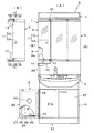
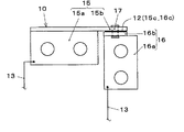
図1は第1及び2の実施の形態に係る本発明キャビネット1,2を備えた洗面化粧台3を示すものであって、(A)は一部破断した正面図、(B)は扉9及び蝶番10,10を示す背面図である。図2は本発明キャビネット1に備えた蝶番10を拡大して示す背面図、図3(A)は本発明キャビネット2に備えた蝶番23を拡大して示す正面図、同図(B)は(A)のb−b線における断面図である。洗面化粧台3は、図1に示す如く、下方のベースキャビネット4と、ベースキャビネット4に支持される洗面器5と、洗面器5より上方に配置したミラーキャビネット6と、照明装置7とを備えている。
FIG. 1 shows a
第1の実施の形態に係る本発明キャビネット1は、ミラーキャビネット6に施したものであり、合成樹脂素材等から成形されたミラーキャビネット本体8に、キャビネット本体8の収納部8aを開閉する扉9を蝶番10,10で揺動自在に取り付け、扉9に発音装置11を設け、各蝶番10に通電部12を設け、発音装置11からキャビネット本体側へ延びる配線13,13の一部を各通電部12で形成してある。配線13,13は、キャビネット本体8の背面外側等を通過して、発音信号発生装置14へ接続される。発音信号発生装置14から出力された電気信号は、各配線13及び各蝶番10の通電部12を通過して発音装置11へ至り、発音装置11を駆動して発音させる。発音装置11から発した音声等は、洗面化粧台3の外側へ拡散して使用者に至る。本発明キャビネット1は、発音装置11を設けた扉9を開閉することで、扉9で覆われるキャビネット本体収納部8aから収納物を出し入れすることができると共に、各配線13の一部を蝶番10に設けた通電部12で形成することで扉9の開閉を円滑にできる。
The cabinet 1 of the present invention according to the first embodiment is applied to a mirror cabinet 6, and a
前記蝶番10は、図2に示す如く、導電素材からなる取付部15a及び軸受部15bを備えた一方の蝶番構成部15と、導電素材からなる取付部16a及び軸受部16bを備えた他方の蝶番構成部16と、両軸受部15b,16bに軸支されて両蝶番構成部15,16を揺動自在に連結する軸部17とを備え、両軸受部15b,16bの摺動面15c,16cどうしを通電可能に接触させて通電部12を設けている。蝶番13は、取付部15a,16a又は軸受部15b,16bに配線13が各々接合され、通電部12を前記電気信号が通過するようになっている。なお、蝶番10は、摺動面15c,16cを導電性に優れた素材(例えば、金メッキ層等)で形成して、電気ノイズの発生を阻止する構造とすることが好ましい。両取付部15a,16aは、図1に示す如く、一方を扉9に接合し、他方をキャビネット本体8に接合してある。
As shown in FIG. 2, the
前記扉9に設けた発音装置11は、扉9の鏡板等からなる表面材を振動板19とし、振動板に振動出力用アクチュエータ18を取り付け、アクチュエータ18の出力で振動板19を振動させて発音させるようになっている。アクチュエータ18は、図示は省略したが、特開平11−266496号公報に掲載されている超磁歪式のものや、ピエゾ素子を用いた形式のものが選択される。このように、発音装置11は、扉9の表面材を振動板19に用いると共にアクチュエータ11で振動させるため小型化でき、キャビネット本体収納部8aの収納量を狭めないようにすることができる。なお、本例の場合、アクチュエータ18は、扉9を閉じたとき、キャビネット本体収納部8aへ突出して格納されるようになつている。
The sounding
なお、発音装置11は、上記形態に限定されるものではなく、図示は省略したが発音信号発生装置14及びアクチュエータ18を一体化又は併設し、扉9の表面材19の表側に発音信号発生装置14及びアクチュエータ18を取り付けることも可能である。この場合、発音信号発生装置14は、音楽ソフトを記憶した記憶媒体(例えば、メモリーカード等)を着脱自在に備えると共に、記憶媒体から音楽ソフトを呼び出すマイコンを備え、音楽ソフト信号を増幅して出力するとよい。配線13は、増幅装置14へ供給する低電圧の電力供給線となる。
Note that the sounding
第2の実施の形態に係る本発明キャビネット2は、図1に示す如く、ベースキャビネット4に施したものであり、ベースキャビネット本体21に、キャビネット本体21の収納部21aを開閉する扉22を蝶番23,23で揺動自在に取り付け、扉22に発音装置24を設け、各蝶番23に通電部25(図3参照)を設け、発音装置24からキャビネット本体側へ延びる配線26,26の一部を各通電部25で形成してある。配線26,26は、キャビネット本体21の内側等を通過して、発音信号発生装置14へ接続される。発音信号発生装置14から出力された電気信号は、各配線26及び各蝶番23の通電部25を通過して発音装置24へ至り、発音装置24を駆動して発音させる。発音装置24から発音は、洗面化粧台3の外側へ音声等として拡散する。本発明キャビネット2は、発音装置24を設けた扉22を開閉することで、扉22で覆われるキャビネット本体収納部21aから収納物を出し入れすることができると共に、各配線26の一部を蝶番23に設けた通電部25で形成することで扉22の開閉を円滑にできる。
The cabinet 2 of the present invention according to the second embodiment is applied to the base cabinet 4 as shown in FIG. 1, and a
前記蝶番23は、図3に示す如く、導電素材からなる取付部27a及び軸受部27bを備えた一方の蝶番構成部27と、導電素材からなる取付部28a及び軸受部28bを備えた他方の蝶番構成部28と、両軸受部27b,28bに軸支され両蝶番構成部27,28を揺動自在に連結する軸部29とを備え、他方の取付部28aに接合した導電性の接触片30を一方の軸受部27bの外周面へ通電可能に接触させて通電部25を設けている。蝶番23は、取付部27a,28aに配線26が各々接合され、通電部25を前記電気信号が通過するようになっている。両取付部27a,28aは、一方を扉22に接合し、他方をキャビネット本体21に接合してある。なお、蝶番23は、通電面となる軸受部27bの外周面及び接触片30の当接面を導電性に優れた素材(例えば、金メッキ層等)で形成して、電気ノイズの発生を阻止する構造とすることが好ましい。蝶番23は、各軸受部27b,28bと軸部29を通電可能に摺動接触させて通電部を設けることもある。
As shown in FIG. 3, the
前記扉22は、図1に示す如く、四角枠状のフレーム31と、フレーム31に振動伝達可能に接合して間に空間部Sを形成する表面材32及び裏面材33と、フレーム31に取り付けた振動出力用アクチュエータ35とを備えている。扉22に設けた発音装置24は、扉22の表面材32及び/又は裏面材33を振動板とし、アクチュエータ35の出力で両振動板32,33を振動させて発音させるようになっている。アクチュエータ35は、図示は省略したが、前記同様に超磁歪式のものや、ピエゾ素子を用いたものが選択される。
As shown in FIG. 1, the
前記扉22は、振動出力用アクチュエータ35から振動伝播具であるフレーム31へ出力された出力振動が、フレーム31の延設方向に沿って広い範囲に伝播して表面材32及び裏面材33を振動させて発音する。扉22は、表面材32及び/又は裏面材33が振動することで、空間部Sで共振を起こして特定の周波数(殊に低音領域)が増強され、大きな音を発生させることができる。
In the
本発明キャビネット21は、扉22の裏面材33に適宜大きさの開口部34を開設し、扉22を閉じたときに扉22の空間部Sとキャビネット本体収納部21aとを連通させるようになっており、扉22の開口部34からキャビネット本体収納部21aへ拡散した音が、キャビネット本体収納部21aで共振を起こし特定の周波数が増強させることができる。
The
なお、本発明キャビネット21は、キャビネット本体収納部21aを開閉する他方の扉37を蝶番23,23で揺動自在に取り付け、扉37に前記発音装置24を設け、左右の発音装置でステレオを構成することも勿論可能である。また、前記扉22や扉37に設ける発音装置24は、フレーム31及び裏面材33を省略して、表面材32にアクチュエータ35を取り付けて、表面材32を振動させて発音させるようにすることも勿論可能である。
In the
本例の洗面化粧台3は、前記本発明キャビネット1及び2を組み合わせて備えているが、一方の本発明キャビネット1又は2を省略することも勿論可能である。本発明キャビネットは、前記洗面化粧台3に適用する以外に、図示は省略したが、シンクを支持する扉付き流し台、加熱調理器を支持する扉付きレンジ台、扉付きの調理台又は扉付きの収納庫等に適用することも勿論可能である。
Although the vanity table 3 of this example is provided with a combination of the present invention cabinets 1 and 2, it is of course possible to omit one of the present invention cabinets 1 or 2. The cabinet of the present invention is not shown in the figure except that it is applied to the
8(21)…キャビネット本体、8a(21a)…収納部、9(22)…扉、10(23)…蝶番、11(24)…発音装置、12(25)…通電部、13(26)…配線、19(32)…振動板(表面材)、33…振動板(裏面材)、18(35)…アクチュエータ 8 (21): Cabinet body, 8a (21a): Storage unit, 9 (22): Door, 10 (23): Hinge, 11 (24) ... Sound generator, 12 (25) ... Current-carrying unit, 13 (26) ... Wiring, 19 (32) ... Diaphragm (surface material), 33 ... Diaphragm (back material), 18 (35) ... Actuator
Claims (2)
The cabinet with a sound generator according to claim 1, wherein the sound generator vibrates the door with a vibration output actuator attached to the door.
Priority Applications (1)
| Application Number | Priority Date | Filing Date | Title |
|---|---|---|---|
| JP2004174984A JP2005349058A (en) | 2004-06-14 | 2004-06-14 | Cabinet provided with sound device |
Applications Claiming Priority (1)
| Application Number | Priority Date | Filing Date | Title |
|---|---|---|---|
| JP2004174984A JP2005349058A (en) | 2004-06-14 | 2004-06-14 | Cabinet provided with sound device |
Publications (1)
| Publication Number | Publication Date |
|---|---|
| JP2005349058A true JP2005349058A (en) | 2005-12-22 |
Family
ID=35583994
Family Applications (1)
| Application Number | Title | Priority Date | Filing Date |
|---|---|---|---|
| JP2004174984A Pending JP2005349058A (en) | 2004-06-14 | 2004-06-14 | Cabinet provided with sound device |
Country Status (1)
| Country | Link |
|---|---|
| JP (1) | JP2005349058A (en) |
Citations (5)
| Publication number | Priority date | Publication date | Assignee | Title |
|---|---|---|---|---|
| JPS58178946U (en) * | 1982-05-21 | 1983-11-30 | 日本ビクター株式会社 | Wall storage furniture with speakers |
| JPS6443689A (en) * | 1987-08-10 | 1989-02-15 | Suzuki House System Kaihatsu | Door |
| JPH0322744U (en) * | 1989-07-19 | 1991-03-08 | ||
| JPH053554U (en) * | 1991-06-27 | 1993-01-19 | 株式会社コトブキ設備 | Door hanging bracket |
| JPH0524854U (en) * | 1991-09-17 | 1993-03-30 | ミサワホーム株式会社 | Hinges for entrance doors |
-
2004
- 2004-06-14 JP JP2004174984A patent/JP2005349058A/en active Pending
Patent Citations (5)
| Publication number | Priority date | Publication date | Assignee | Title |
|---|---|---|---|---|
| JPS58178946U (en) * | 1982-05-21 | 1983-11-30 | 日本ビクター株式会社 | Wall storage furniture with speakers |
| JPS6443689A (en) * | 1987-08-10 | 1989-02-15 | Suzuki House System Kaihatsu | Door |
| JPH0322744U (en) * | 1989-07-19 | 1991-03-08 | ||
| JPH053554U (en) * | 1991-06-27 | 1993-01-19 | 株式会社コトブキ設備 | Door hanging bracket |
| JPH0524854U (en) * | 1991-09-17 | 1993-03-30 | ミサワホーム株式会社 | Hinges for entrance doors |
Similar Documents
| Publication | Publication Date | Title |
|---|---|---|
| JP3644356B2 (en) | Musical sound generation structure of electronic musical instruments | |
| TW200537962A (en) | Loudspeakers | |
| EP2027749A1 (en) | Household appliance | |
| JP2010081142A (en) | Panel-shaped speaker | |
| US7078611B2 (en) | Keyboard instrument | |
| JP2001157642A (en) | Sound reproducing device for bathroom | |
| KR970702558A (en) | Electronic device such as recording and / or reproducing device for recording medium | |
| JP2005202189A (en) | Electronic musical instrument | |
| CN101763850A (en) | Casing structure of electronic musical instrument | |
| US20200082799A1 (en) | Sound diffuser accessory | |
| JP2003079528A (en) | Sound reproducing arrangement for bath unit | |
| JP2008299169A (en) | Speaker unit for electronic musical instruments | |
| US11423868B2 (en) | Keyboard device and musical sound emission method | |
| JP2004351038A (en) | Bathroom sound system | |
| JP3550555B2 (en) | Bathroom sound reproducer | |
| JP4468075B2 (en) | Speaker | |
| CN209914050U (en) | Sound device, ventilation fan and Yuba | |
| JP2008292738A (en) | Electronic keyboard instrument | |
| JP7354574B2 (en) | toilet seat device | |
| JP3356744B2 (en) | Sound reproduction device in bathroom | |
| CN209880142U (en) | A good-sounding electric piano | |
| JP2004113388A5 (en) | ||
| JP2004170746A (en) | Keyboard instrument | |
| JP3589873B2 (en) | Picture book with sound | |
| JP2009063341A (en) | Electronic metronome |
Legal Events
| Date | Code | Title | Description |
|---|---|---|---|
| A621 | Written request for application examination |
Free format text: JAPANESE INTERMEDIATE CODE: A621 Effective date: 20061220 |
|
| A131 | Notification of reasons for refusal |
Free format text: JAPANESE INTERMEDIATE CODE: A131 Effective date: 20091119 |
|
| A02 | Decision of refusal |
Effective date: 20100318 Free format text: JAPANESE INTERMEDIATE CODE: A02 |