JP2005292551A - Multi-core optical fiber branch structure - Google Patents
Multi-core optical fiber branch structure Download PDFInfo
- Publication number
- JP2005292551A JP2005292551A JP2004108903A JP2004108903A JP2005292551A JP 2005292551 A JP2005292551 A JP 2005292551A JP 2004108903 A JP2004108903 A JP 2004108903A JP 2004108903 A JP2004108903 A JP 2004108903A JP 2005292551 A JP2005292551 A JP 2005292551A
- Authority
- JP
- Japan
- Prior art keywords
- optical fiber
- core optical
- core
- sheets
- branching
- Prior art date
- Legal status (The legal status is an assumption and is not a legal conclusion. Google has not performed a legal analysis and makes no representation as to the accuracy of the status listed.)
- Pending
Links
Images


Abstract
Description
この発明は、多心光ファイバを分岐させる際に、分岐部を2枚のシートで挟み込んだ構造の多心光ファイバ分岐構造に関する。 The present invention relates to a multi-fiber optical fiber branch structure in which a branch portion is sandwiched between two sheets when a multi-fiber optical fiber is branched.
従来、多心光ファイバ、例えばテープ心線を2分岐以上に分岐させる場合、テープ心線の分岐部を粘着剤付きの上下2枚のシートで挟み込むことで分岐部の補強を行う場合がある。この分岐に際して、テープ心線を特に単心光ファイバに分離する場合は、この単心光ファイバの取り扱いが不便であるとともに断線の恐れもあるため、通常小径の保護チューブで保護する。この種の従来の多心光ファイバ分岐構造の一例を図9、図10に示す。図示例は分岐前の多心光ファイバ1が8心のテープ心線であって、この8心のテープ心線(多心光ファイバ)1を2分岐する場合であり、分離させた8本の光ファイバ(単心光ファイバ)2を4本ずつ2群に分け、それぞれを保護チューブ3内に収容し、分岐部を保護チューブ3の端部を含めて、上下2枚の粘着剤付きのシート4、5で挟み込んで固定している。なお、シートの粘着剤は上下のシート4、5の少なくとも一方に塗布されておればよい。
Conventionally, when a multi-core optical fiber, for example, a tape core wire is branched into two or more branches, the branch portion may be reinforced by sandwiching the branch portion of the tape core wire between upper and lower sheets with an adhesive. At the time of this branching, when the tape core is separated into a single-core optical fiber, the single-core optical fiber is inconvenient to handle and may be broken. An example of this type of conventional multi-core optical fiber branching structure is shown in FIGS. The illustrated example is a case where the multi-core
図示のように、従来の多心光ファイバ分岐構造は、上下のシート4、5同士が、横並びの保護チューブ3の両側aでしっかり粘着して、分岐部及び保護チューブ3の端部を固定するように、シート4、5の幅を十分広くとっている。
上記従来の多心光ファイバ分岐構造では、上下のシート4、5で横並びの保護チューブ3を挟み込んでしっかり固定するために、シート4、5の幅を、横並びの保護チューブ3の全幅より十分広く取る必要があり、このため大きなシート4、5が必要で、このシート4、5部分すなわち分岐構造部分が広いスペースを占めてしまうという問題がある。
また、保護チューブ3の径は例えば2mmφ等であり、光ファイバ2の径と比べて大きく、シート4、5同士の密着力を低下させるので、この保護チューブ3の部分でシート4、5が剥がれてしまう恐れがある。
In the conventional multi-core optical fiber branching structure, the widths of the sheets 4 and 5 are sufficiently wider than the entire width of the side-by-
The diameter of the
本発明は上記従来の欠点を解消するためになされたもので、多心光ファイバを、上下から挟み込むシートを用いて分岐させる際に、分岐部の安定した固定がなされて長期信頼性を向上させることができるとともに、分岐構造部分をコンパクトにすることができる多心光ファイバ分岐構造を提供することを目的とする。 The present invention has been made to eliminate the above-described conventional drawbacks, and when a multi-fiber optical fiber is branched using a sheet sandwiched from above and below, the branching portion is stably fixed to improve long-term reliability. An object of the present invention is to provide a multi-core optical fiber branching structure that can make the branching structure compact.
上記課題を解決する本発明は、多心光ファイバをこの多心光ファイバより少心の複数の光ファイバに分岐する際に、その分岐部を、分岐後の光ファイバにそれぞれ被せた保護チューブの端部を含めて、上下2枚の軟質樹脂製のシートで挟み込んでなる多心光ファイバ分岐構造において、
前記シートの幅を、上下のシート同士が互いに貼り合わされない程度の短い幅とし、かつ、少なくともシート部分全体を熱収縮チューブ内に収容固定したことを特徴とする。
The present invention that solves the above-mentioned problems is that when a multi-fiber optical fiber is branched into a plurality of optical fibers having a smaller number of cores than the multi-fiber optical fiber, the branch portions of the protective tubes are respectively covered with the branched optical fibers. In the multi-core optical fiber branching structure sandwiched between two soft resin sheets, including the end part,
The width of the sheet is such a short width that the upper and lower sheets are not bonded to each other, and at least the entire sheet portion is accommodated and fixed in a heat-shrinkable tube.
請求項2は、請求項1の多心光ファイバ分岐構造において、上下のシートの幅が、互いに接触して横並びした複数の保護チューブの全幅と同程度であることを特徴とする。 According to a second aspect of the present invention, in the multi-core optical fiber branching structure according to the first aspect, the width of the upper and lower sheets is approximately the same as the total width of the plurality of protective tubes arranged in contact with each other.
請求項3は、請求項1又は2の多心光ファイバ分岐構造において、分岐前の多心光ファイバがテープ心線であることを特徴とする。 According to a third aspect of the present invention, in the multi-core optical fiber branching structure according to the first or second aspect, the multi-core optical fiber before branching is a tape core.
請求項4は、請求項1又は2の多心光ファイバ分岐構造において、分岐前の多心光ファイバが被覆チューブ内に単心又は多心の光ファイバを収容した構成であり、この被覆チューブの端部も、上下2枚のシートで挟み込んだことを特徴とする。 According to a fourth aspect of the present invention, in the multi-fiber optical fiber branching structure according to the first or second aspect, the multi-fiber optical fiber before branching is configured so that a single-core or multi-core optical fiber is accommodated in the coated tube. The end portion is also sandwiched between two upper and lower sheets.
本発明によれば、シート同士の粘着力は利用しないので、シートの幅を例えば横並びの保護チューブの全幅程度に狭くすることができ、したがって、分岐構造部分をコンパクトにすることができる。
一方、幅の狭いシートで保護チューブを挟み込んだその上から熱収縮チューブで固定するので、シートの幅の狭いことは問題にならず、分岐部の安定した固定がなされて長期信頼性が向上する。
According to the present invention, since the adhesive force between the sheets is not utilized, the width of the sheet can be reduced to, for example, about the entire width of the side-by-side protection tubes, and thus the branch structure portion can be made compact.
On the other hand, the protective tube is sandwiched between narrow sheets and fixed with a heat-shrinkable tube, so that the narrow width of the sheet is not a problem and stable fixing of the bifurcation is achieved, improving long-term reliability. .
請求項3のように分岐前の多心光ファイバがテープ心線である場合が、分岐部を上下のシートで挟み込む構造に適しており、本発明を適用する対象として好適である。
The case where the multi-core optical fiber before branching is a tape core as in
請求項4のように、分岐前の多心光ファイバが保護チューブ内に単心又は多心の光ファイバを収容したものである場合、この分岐前側の保護チューブをしっかり固定するためにシート幅が広くなり勝ちであるが、本発明によればそのような場合でも、分岐構造部分が広くならない。 When the multi-core optical fiber before branching is a single-core or multi-core optical fiber accommodated in a protective tube as in claim 4, the sheet width is set to firmly fix the pre-branch side protective tube. Although it tends to be wide, according to the present invention, even in such a case, the branched structure portion does not become wide.
以下、本発明を実施した多心光ファイバ分岐構造について、図面を参照して説明する。 Hereinafter, a multi-core optical fiber branching structure embodying the present invention will be described with reference to the drawings.
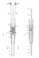
図1は本発明の一実施例の多心光ファイバ分岐構造10を示すもので、(イ)は部分切欠平面図、(ロ)部分切欠側面図、図2(イ)は図1(イ)のA−A拡大断面図、図2(ロ)は図1(イ)のB−B拡大断面図である。図示例は分岐前の多心光ファイバ1が8心のテープ心線であって、この8心のテープ心線(多心光ファイバ)1を2分岐する場合であり、分離させた8本の光ファイバ(単心光ファイバ)2を4本ずつ2群に分け、それぞれを互いに接触して横並びした保護チューブ3内に収容し、分岐部は、保護チューブ3の端部を含めて、それぞれ粘着剤を内側面に塗布した上下の軟質樹脂製のシート14、15で挟み込んでいる。なお、光ファイバ2の保護チューブ3への入口部は、接着剤bで保護チューブ3の端部に固定している。
FIG. 1 shows a multi-core optical
前記シート14、15の幅は、上下のシート14、15同士が互いに貼り合わされない程度の短い幅であるが、実施例では図2(イ)のように、横並びの保護チューブ3の全幅程度であり、上下のシート14、15は互いに接触していない。そして、シート14、15部分の長手方向全体及びその前後部分を、熱収縮チューブ16で収容固定している。具体的な作業手順としては、加熱前の熱収縮チューブをテープ心線1に通しておき、分岐部を上下からシート14、15で挟み込んだ後、スライドさせてシート14、15部分に被せ、次いで加熱して収縮させ、図示のように、分岐部を固定する。
The width of the
前記シート14、15の厚みは例えば0.5mm、保護チューブ3の径は2mmφである。シート14、15の材質は、一般的な光ファイバシートに用いられる軟質樹脂であり、例えばポリイミドが好適であるが、その他、ポリエチレンテレフタレート、低密度あるいは高密度ポリエチレン、ポリプロピレン、ポリエステル、ナイロン6、ナイロン66、エチレン−テトラフルオルエチレン共重合体、ポリ4−メチルペンテン、ポリ塩化ビニリデン、可塑化ポリ塩化ビニル、ポリエーテルエステル共重合体、エチレン−酢酸ビニル共重合体、軟質ポリウレタン等を用いることができる。保護チューブ3の材質としては、ナイロン、ハイトレル(デュポン社商標)等を用いることができる。熱収縮チューブ16の材質は、シリコーン樹脂やビニル樹脂(架橋ポリオレフィン)やフッ素樹脂等を用いることができる。また、図示例のテープ心線1は、250μmのUV素線である光ファイバ2を図2(ロ)に示すように、単に整列させて接着剤で固めたものである。なお、分岐前のテープ心線は図3のように被覆1aを持つテープ心線1’であっても、同様な分岐処理を行うことができる。
The thickness of the
上記の多心光ファイバ分岐構造10において、上下のシート14、15の幅は図示のように横並びの保護チューブ3の全幅程度であり、図9、図10に示した従来のものと比較してかなり狭くなっている。したがって、分岐構造部分をコンパクトにすることができる。
幅の狭い上下のシート4、5はそれぞれ保護チューブ3の上面又は下面に粘着しているが、シート14、15同士は互いに接触せず、互いに粘着されてはいない。しかし、シート14、15部分の全体を熱収縮チューブ16で収容固定しているので、分岐部の安定した固定がなされて長期信頼性が向上する。
In the multi-fiber optical
The narrow upper and lower sheets 4 and 5 are adhered to the upper surface or the lower surface of the
上記の実施例では、分離させた8本の単心光ファイバ2を4本ずつの2群に分けて、各保護チューブ3に収容したが、図4に示すように、8心のテープ心線1を2本の4心テープ心線22に分岐させて、各4心テープ心線22を2本の保護チューブ3にそれぞれ収容する分岐構造としてもよい。
In the above embodiment, the separated eight single-core
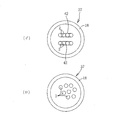
また、8心のテープ心線1を、図5(イ)に示すように4本の2心テープ心線32に分岐させて、各2心テープ心線32を4本の保護チューブ3にそれぞれ収容する分岐構造としてもよい。
Further, as shown in FIG. 5 (a), the 8-
また、多心光ファイバ1を、単心光ファイバと多心光ファイバとが混在する態様で分岐させてもよい。図5(ロ)はその一例を示すもので、図示例では、4本の保護チューブ3に分岐する場合であり、各保護チューブ3にそれぞれ、2本の2心テープ心線32、1本の2心テープ心線32、1本の単心光ファイバ2、1本の単心光ファイバ2を収容している。
Further, the multi-core
上述の各実施例は分岐前の多心光ファイバ1がテープ心線1であるが、分岐前の多心光ファイバが、図6〜図8に示すように、被覆チューブ18内に単心又は多心の光ファイバを収容した構成であってもよい。
図6、図7に示した分岐前の多心光ファイバ17は、1本の8心テープ心線1を被覆チューブ18内に収容したものである。
また、図8(イ)に示した分岐前の多心光ファイバ27は、2本の4心テープ心線42を被覆チューブ18内に収容したものである。
また、図8(ロ)に示した分岐前の多心光ファイバ37は、8本の単心光ファイバ2を被覆チューブ18内に収容したものである。
In each of the above-described embodiments, the multi-core
The multi-fiber
Further, the multi-fiber
Further, the multi-fiber
1、1’ 多心光ファイバ(テープ心線)
2 単心光ファイバ
3 保護チューブ
10 多心光ファイバ分岐構造
14、15 シート
16 熱収縮チューブ
18 被覆チューブ
17、27、37 多心光ファイバ
1, 1 'multi-core optical fiber (tape core)
2 Single-core
Claims (4)
前記シートの幅を、上下のシート同士が互いに貼り合わされない程度の短い幅とし、かつ、少なくともシート部分全体を熱収縮チューブ内に収容固定したことを特徴とする多心光ファイバ分岐構造。 When a multi-core optical fiber is branched into a plurality of optical fibers with fewer cores than the multi-core optical fiber, the bifurcated portion includes two ends, including the end of the protective tube that covers each of the branched optical fibers. In a multi-core optical fiber branching structure sandwiched between sheets of soft resin,
A multi-core optical fiber branching structure characterized in that the width of the sheet is short enough to prevent the upper and lower sheets from being bonded to each other, and at least the entire sheet portion is accommodated and fixed in a heat-shrinkable tube.
Priority Applications (1)
| Application Number | Priority Date | Filing Date | Title |
|---|---|---|---|
| JP2004108903A JP2005292551A (en) | 2004-04-01 | 2004-04-01 | Multi-core optical fiber branch structure |
Applications Claiming Priority (1)
| Application Number | Priority Date | Filing Date | Title |
|---|---|---|---|
| JP2004108903A JP2005292551A (en) | 2004-04-01 | 2004-04-01 | Multi-core optical fiber branch structure |
Publications (1)
| Publication Number | Publication Date |
|---|---|
| JP2005292551A true JP2005292551A (en) | 2005-10-20 |
Family
ID=35325523
Family Applications (1)
| Application Number | Title | Priority Date | Filing Date |
|---|---|---|---|
| JP2004108903A Pending JP2005292551A (en) | 2004-04-01 | 2004-04-01 | Multi-core optical fiber branch structure |
Country Status (1)
| Country | Link |
|---|---|
| JP (1) | JP2005292551A (en) |
Cited By (3)
| Publication number | Priority date | Publication date | Assignee | Title |
|---|---|---|---|---|
| JP2007304551A (en) * | 2006-05-11 | 2007-11-22 | Corning Cable Systems Llc | Fiber optic distribution cable and structure therefor |
| JP2009175480A (en) * | 2008-01-25 | 2009-08-06 | Tohoku Furukawa Denko Kk | Optical fibre branch module |
| WO2017110114A1 (en) * | 2015-12-25 | 2017-06-29 | 株式会社フジクラ | Optical fiber cable branching member and optical fiber cable branching structure |
-
2004
- 2004-04-01 JP JP2004108903A patent/JP2005292551A/en active Pending
Cited By (6)
| Publication number | Priority date | Publication date | Assignee | Title |
|---|---|---|---|---|
| JP2007304551A (en) * | 2006-05-11 | 2007-11-22 | Corning Cable Systems Llc | Fiber optic distribution cable and structure therefor |
| US9494764B2 (en) | 2006-05-11 | 2016-11-15 | Corning Optical Communications LLC | Fiber optic distribution cables and structures therefor |
| JP2009175480A (en) * | 2008-01-25 | 2009-08-06 | Tohoku Furukawa Denko Kk | Optical fibre branch module |
| WO2017110114A1 (en) * | 2015-12-25 | 2017-06-29 | 株式会社フジクラ | Optical fiber cable branching member and optical fiber cable branching structure |
| JPWO2017110114A1 (en) * | 2015-12-25 | 2018-07-12 | 株式会社フジクラ | Optical fiber cable branching member and optical fiber cable branching structure |
| US10725261B2 (en) | 2015-12-25 | 2020-07-28 | Fujikura Ltd. | Optical fiber-cable branch member and optical fiber-cable branch structure |
Similar Documents
| Publication | Publication Date | Title |
|---|---|---|
| US4138193A (en) | Multiple fiber laminate for optical waveguides | |
| JP2000089068A (en) | Reinforced type optical fiber cable | |
| US8388242B2 (en) | In-line splice with integrated splice holder | |
| ES2091965T3 (en) | SLOTTED NUCLEO CABLE FOR FIBER OPTIC TAPES AND PROCEDURE FOR ITS MANUFACTURE. | |
| WO2014054129A1 (en) | Optical fiber tape core | |
| JP2004361521A (en) | Tape-like coated optical fiber | |
| JP2014074910A (en) | Coated optical fiber tape | |
| JP2005292551A (en) | Multi-core optical fiber branch structure | |
| JP3773584B2 (en) | Fiber optic tape cable | |
| JPH09230184A (en) | Optical fiber tape | |
| KR20060087443A (en) | Optical fiber cable | |
| JP3774173B2 (en) | Fiber optic cable | |
| JP4249202B2 (en) | Optical fiber tape and optical cable | |
| JPH01150106A (en) | Tape-shaped optical fiber | |
| JP2006322721A (en) | Optical fiber sensor | |
| JPH07159629A (en) | Coated optical fiber tape unit and optical cable | |
| JP2005249977A (en) | Fiber optic cable | |
| CN213814032U (en) | Heat shrink tube | |
| JP2008164679A (en) | Branch structure of multi-core optical fiber with optical connector | |
| JPH10148741A (en) | Optical fiber ribbon | |
| WO2003083546A1 (en) | Optical fiber core | |
| JP4030800B2 (en) | Optical fiber sheet | |
| JPH095592A (en) | Optical fiber cord | |
| JP2001033669A (en) | Overhead-laid optical fiber cable | |
| JP2012208433A (en) | Optical fiber ribbon |