JP2005261120A - Multiaxial servo drive - Google Patents
Multiaxial servo drive Download PDFInfo
- Publication number
- JP2005261120A JP2005261120A JP2004070672A JP2004070672A JP2005261120A JP 2005261120 A JP2005261120 A JP 2005261120A JP 2004070672 A JP2004070672 A JP 2004070672A JP 2004070672 A JP2004070672 A JP 2004070672A JP 2005261120 A JP2005261120 A JP 2005261120A
- Authority
- JP
- Japan
- Prior art keywords
- connector
- power
- servo
- servo amplifier
- unit
- Prior art date
- Legal status (The legal status is an assumption and is not a legal conclusion. Google has not performed a legal analysis and makes no representation as to the accuracy of the status listed.)
- Pending
Links
Images


Classifications
-
- Y02P80/116—
Abstract
Description
本発明は、FAにおけるロボットなど複数のサーボモータを駆動制御する多軸サーボドライブ装置に関する。 The present invention relates to a multi-axis servo drive device that drives and controls a plurality of servo motors such as a robot in an FA.
図3は、従来技術の多軸サーボドライブ装置の配線接続例を示す外観斜視図である。
図3において、1は1台のサーボモータを駆動制御するサーボアンプユニットであって、ネットワークサーボを構成しており、2は交流電力を直流電力に変換して各軸のサーボアンプユニット1へ供給するコンバータユニット、3はネットワークケーブル接続用コネクタ、4はネットワークケーブル、7はコンバータユニット2からの直流電源出力、10はモータへの動力ケーブル、13はエンコーダケーブル、19はコンバータユニット2ヘ入力される交流電源用のケーブル、21は各軸の入出力を一括して取り込みネットワークで各軸に指令を出すマスターユニット、22はネットワークの終端のターミネータである。
図4は従来技術および本発明の実施例に共通なサーボアンプユニット単体の外観図であり、図5は従来技術および本発明の実施例に共通なコンバータユニット単体の外観図である。なお、図4および図5において図3と同じ説明符号のものは、図3と同じ構成要素および機能を示している。
図4および図5において、5は直流電源接続コネクタ、6は直流電源接続コネクタ5と嵌合可能な直流電源ケーブル接続コネクタ、8はモータ動力接続用コネクタ、9はモータ動力接続用コネクタ8と嵌合可能なモータ動力ケーブル接続用コネクタ、11はエンコーダ接続コネクタ、12はエンコーダ接続コネクタ11と嵌合可能なエンコーダケーブル接続コネクタ、14はネットワーク接続用コネクタ3と嵌合可能なネットワーク接続用コネクタ、15は直流電源出力コネクタ、16は直流出力コネクタ15と嵌合可能な直流電源ケーブル接続コネクタ、17は交流電源入力コネクタ、18は交流電源入力コネクタ17と嵌合可能な交流電源ケーブル接続コネクタである。
以下、図3、4、5を用いて従来技術の多軸サーボドライブ装置の配線接続について説明する。図3の例では、3台のサーボモータを駆動する3軸構成の多軸サーボドライブ装置を示している。一般に、各サーボアンプユニット1およびコンバータユニット2は横に並べられて取付けられている。コンバータユニット2からの直流電源出力7は、コンバータユニット2に設けられた直流電源出力コネクタ15から直流電源ケーブル接続コネクタ16を経て出力され、端子台(図示せず)で分岐され、直流電源ケーブル接続コネクタ6を経て、サーボアンプユニット1に設けられた直流電源接続コネクタ5から供給される。
サーボアンプユニット1、コンバータユニット2とマスターユニット21との信号伝送のため、それぞれに設けられたネットワーク接続用コネクタ3間で渡り配線が行なわれる。
サーボモータへの動力ケーブル10は、それぞれ個別にモータ動力ケーブル接続用コネクタ9を介して配線していた。
ところが、この構成の多軸サーボドライブ装置では、サーボアンプユニット1を交換するにはコネクタやケーブルをいちいち外す必要が有ることから、配線の簡素化による作業性向上とコネクタの個数の削減によるコスト削減を目的として、回路基板に予め必要な回路配線を施してマウントベースを形成し、各サーボアンプユニットおよびコンバータユニットを該回路基板に配置固定する方法が従来考えられてきた(例えば、特許文献1を参照)。
In FIG. 3, 1 is a servo amplifier unit that drives and controls one servo motor, which constitutes a network servo, and 2 converts AC power into DC power and supplies it to the
4 is an external view of a single servo amplifier unit common to the prior art and embodiments of the present invention, and FIG. 5 is an external view of a single converter unit common to the prior art and embodiments of the present invention. 4 and 5, the same reference numerals as those in FIG. 3 indicate the same components and functions as those in FIG.
4 and 5, 5 is a DC power supply connector, 6 is a DC power cable connector that can be fitted to the DC power supply connector 5, 8 is a motor power connector, and 9 is a motor power connector 8. A connector for connecting a motor power cable, 11 an encoder connector, 12 an encoder cable connector that can be fitted with the
Hereinafter, the wiring connection of the conventional multi-axis servo drive device will be described with reference to FIGS. In the example of FIG. 3, a multi-axis servo drive device having a three-axis configuration for driving three servo motors is shown. In general, each
For signal transmission between the
The
However, in the multi-axis servo drive device of this configuration, it is necessary to remove the connectors and cables one by one in order to replace the
しかしながら、ロボットでは、マニュピレータと多軸サーボドライブ装置間のサーボモータの動力線はまとめて一体のケーブルを用い、一つのコネクタで結合する事が求められており、従来技術の様に、モータの動力線やモータ動力ケーブル接続用コネクタがそれぞれ別々という構成は忌避されるという問題があった。さらに、従来のマウントベースではサーボアンプユニット自体の脱着が簡便ではなく、また、サーボアンプユニットを一軸づつ分散配備するといったことが困難であるという問題もあった。
本発明はこのような問題に鑑みてなされたものであり、簡単に脱着可能で、各軸のモータの動力線の配線を一つのコネクタに統合することが可能で、更に一軸づつ分散配備が可能な多軸サーボドライブ装置を提供することを目的とする。
However, in robots, the power lines of the servo motor between the manipulator and the multi-axis servo drive device are required to be connected together using a single cable and connected with a single connector. There is a problem that the configuration in which the wires and the connectors for connecting the motor power cables are separate is avoided. Further, the conventional mount base has a problem that it is not easy to attach and detach the servo amplifier unit itself, and it is difficult to disperse and arrange the servo amplifier units one by one.
The present invention has been made in view of such a problem, and can be easily attached / detached, the wiring of the power lines of the motors of the respective axes can be integrated into a single connector, and further distributed in a single axis is possible. An object of the present invention is to provide a multi-axis servo drive device.
上記問題を解決するため、請求項1記載の発明は、交流電力を直流電力に変換するコンバータユニットと、前記直流電力を交流制御電力に変換してサーボモータを駆動する複数のサーボアンプユニットを備えた多軸サーボドライブ装置において、前記コンバータユニットおよび前記サーボアンプユニットは、それぞれ個別にケーブル接続することが可能な電気配線用のコネクタを有しており、各々のユニットに設けた前期電気配線用のコネクタは、各コネクタ間を接続するために必要な回路配線を予め施した回路基板を有するマウントベース上に嵌合接続されており、前記回路基板は、前記直流電力を分散配備された前記サーボアンプユニットへ出力するための直流電力用コネクタと、前記複数のサーボアンプユニットからサーボモータへの動力線を一つに統合して接続するサーボモータ動力線用コネクタを有することを特徴としている。
また、請求項2記載の発明は、請求項1記載の多軸サーボドライブ装置において、前記サーボアンプユニットは、ネットワークサーボを構成するものであり、 前記回路基板は、前記サーボアンプユニットと別置きのマスターユニットとをネットワークで接続するためのネットワーク接続コネクタを有することを特徴としている。
In order to solve the above problem, an invention according to
According to a second aspect of the present invention, in the multi-axis servo drive device according to the first aspect, the servo amplifier unit constitutes a network servo, and the circuit board is provided separately from the servo amplifier unit. It has a network connection connector for connecting to the master unit via a network.
請求項1記載の多軸サーボドライブ装置によれば、サーボアンプユニットおよびコンバータユニットのコネクタと嵌合でき、ケーブルを接続可能なコネクタと同じ嵌合を有するコネクタを回路基板に設けて、ここにサーボアンプユニットやコンバータユニットを取付けることによりベースマウントタイプの多軸サーボドライブ装置が実現できる構成にしているため、サーボアンプユニットやコンバータユニットが簡単に脱着可能である。
また、前記回路基板は直流電力を分散配備されたサーボアンプユニット用の直流電力用コネクタに出力し、且つ、該多軸サーボドライブ装置のサーボアンプユニットはケーブル付きコネクタによる配線も出来る構成としているため、一軸づつ分散配備することも可能である。
更に、本発明の多軸サーボドライブ装置は、各軸のサーボモータ動力線の配線が一つのコネクタに統合する構成としているので、ロボットにおける動力線一体ケーブル化の要求を満たすことが可能である。
請求項2記載の多軸サーボドライブ装置によれば、前記サーボアンプユニットはネットワークサーボの構成としているので、マスターユニットは、ネットワークを用いて各軸の入出力を一括して取り込み、各軸に指令を出すことができる。
According to the multi-axis servo drive device of the first aspect, the circuit board is provided with a connector that can be fitted to the connector of the servo amplifier unit and the converter unit and has the same fitting as the connector to which the cable can be connected. Since the base mount type multi-axis servo drive device can be realized by mounting the amplifier unit and converter unit, the servo amplifier unit and converter unit can be easily attached and detached.
In addition, the circuit board outputs DC power to the DC power connector for the servo amplifier unit that is distributed, and the servo amplifier unit of the multi-axis servo drive device is configured to allow wiring with a connector with a cable. It is also possible to disperse and deploy one axis at a time.
Furthermore, since the multi-axis servo drive device of the present invention is configured such that the wiring of the servo motor power lines of each axis is integrated into one connector, it is possible to satisfy the demand for the power line integrated cable in the robot.
According to the multi-axis servo drive device according to claim 2, since the servo amplifier unit is configured as a network servo, the master unit collects input / output of each axis collectively using the network and instructs each axis. Can be issued.
以下、本発明の具体的実施例について、図に基づいて説明する。 Hereinafter, specific examples of the present invention will be described with reference to the drawings.
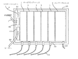
図1は本発明の実施例を示す外観図であり、5軸分のサーボアンプユニットによる多軸サーボドライブ装置を構成した例を示している。
図2は本発明の実施例を示すマウントベースの構造図である。
図1および図2において、図4および図5と同じ説明符号のものは図4および図5と同じ構成要素および機能を示している。
図1および図2において、30は回路基板すなわちプリント基板、31はサーボアンプユニット1のコネクタ14と嵌合可能なネットワーク接続コネクタ、32はサーボアンプユニット1のコネクタ5と嵌合可能な直流入力電源接続コネクタ、33はサーボアンプユニット1のコネクタ8と嵌合可能なモータ動力接続コネクタ、34はコンバータユニット2のコネクタ15と嵌合可能な直流出力電源接続コネクタ、35はマウントベース、36はネットワークの終端のターミネータ、37はコンバータユニット2のコネクタ14と嵌合可能なネットワーク接続コネクタ、38はマスターユニットへのネットワーク接続コネクタ、39は分散設置サーボアンプユニット用の直流電力用コネクタ、40はサーボモータへの動力線用コネクタ、41はマスターユニットへのネットワーク接続コネクタ38と嵌合可能なネットワーク配線接続コネクタ、42はコネクタ39と嵌合可能な分散設置サーボアンプユニット用の直流電源ケーブル接続コネクタ、43はコネクタ40と嵌合可能な動力供給用集合ケーブル接続コネクタ、44はサーボモータへの動力供給用集合ケーブルである。
本発明が従来技術と異なる点は、コンバータユニット2およびサーボアンプユニット1は、それぞれ個別にケーブル接続することが可能な電気配線用のコネクタ5、8、14、15を有しており、各々のユニット1、2に設けた電気配線用のコネクタ5、8、14、15は、各コネクタ間を接続するために必要な回路配線を予め施した回路基板30を有するマウントベース35上に嵌合接続されており、回路基板30は、直流電力を分散配備されたサーボアンプユニット1へ出力するための直流電力用コネクタ39と、複数のサーボアンプユニット1からサーボモータへの動力線を一つに統合して接続するサーボモータ動力線用コネクタ40を有する点と、サーボアンプユニット1は、ネットワークサーボを構成するものであり、回路基板30は、前記サーボアンプユニット1と別置きのマスターユニットとをネットワーク4で接続するためのネットワーク接続コネクタ38を有する点である。
FIG. 1 is an external view showing an embodiment of the present invention, and shows an example in which a multi-axis servo drive device is constituted by servo amplifier units for five axes.
FIG. 2 is a structural view of a mount base showing an embodiment of the present invention.
1 and 2, the same reference numerals as those in FIGS. 4 and 5 indicate the same components and functions as those in FIGS.
1 and 2, 30 is a circuit board, that is, a printed board, 31 is a network connection connector that can be fitted to the
The difference between the present invention and the prior art is that the converter unit 2 and the
さらに、本発明の実施例を、図1および図2を用いて詳細な説明を行なう。
マウントベース35の上には回路基板30が備えられている。回路基板30上には、サーボアンプユニット1の前面パネル上にある直流電源接続コネクタ5、モータ動力接続用コネクタ8およびネットワーク接続用コネクタ14と嵌合して電気接続可能なコネクタ31、32、33をそれぞれ5組配置している。さらに、回路基板30上には、コンバータユニット2の前面パネル上にある直流出力コネクタ15およびネットワーク接続用コネクタ14と嵌合して電気接続可能なコネクタ37、34を配置している。
これらのコネクタ31、32、33、34、37は、サーボアンプユニット1の前面パネルのコネクタ5、8、14と回路基板30上のコネクタ31、32、33を同時に嵌合でき、コンバータユニット2の前面パネルのコネクタ14、15と回路基板30のコネクタ37、34を同時に嵌合でき、5台のサーボアンプユニット1とコンバータユニット2が集合並置となる位置に配置している。すなわち、サーボアンプユニット1およびコンバータユニット2の前面パネルのコネクタ位置に対応させた位置に配置している。
コンバータユニット2の直流電源出力はコネクタ34から回路基板30に出力され、回路基板30上のコネクタ32を通じて各サーボアンプユニット1に取り込まれると共に、コネクタ39に出力するように予め回路基板30には配線がなされており、コネクタ39から分散配備されたサーボアンプユニットへ直流電源の供給が可能である。
また、各々のサーボアンプユニット1のコネクタ8から回路基板30上のコネクタ33を通じて回路基板30に取り込まれた各軸のサーボモータの動力は、回路基板30上の1つのコネクタ40に集められるよう予め回路基板30には配線がなされている。
また、回路基板30上のコネクタ31、37、38は予めネットワークのための配線がなされており、ネットワークの信号の終端にはターミネータ36が接続されており、回路基板30上のコネクタ38からネットワークケーブル4により、回路基板30の外部に設置されたマスターユニットと結合できる。
Further, an embodiment of the present invention will be described in detail with reference to FIGS.
A
These
The DC power output of the converter unit 2 is output from the
Further, the power of the servo motor of each axis taken into the
The
以上述べたように、本発明の実施例に係る多軸サーボドライブ装置は、サーボアンプユニット1およびコンバータユニット2のコネクタ5、8、14、15と嵌合でき、ケーブルを接続可能なコネクタ6、9、3、16と同じ嵌合を有するコネクタ31、32、33、34、37を回路基板30に設けて、ここにサーボアンプユニット1やコンバータユニット2を取付けることによりベースマウントタイプの多軸サーボドライブ装置が実現できる構成にしたので、サーボアンプユニット1やコンバータユニット2を簡単に脱着することができる。また、回路基板30は直流電力を分散配備されたサーボアンプユニット用の直流電力用コネクタ39に出力し、且つ、該多軸サーボドライブ装置のサーボアンプユニット1はケーブル付きコネクタ3、6、9による配線も出来る構成としたので、一軸づつ分散配備することもできる。
また、本発明の実施例に係る多軸サーボドライブ装置は、各軸のサーボモータ動力線の配線が一つのコネクタ40に統合する構成としたので、ロボットにおける動力線一体ケーブル化の要求を満たすことができる。
更に、本発明の実施例に係る多軸サーボドライブ装置は、サーボアンプユニット1はネットワークサーボの構成としたので、マスターユニットは、ネットワーク4を用いて各軸の入出力を一括して取り込み、各軸に指令を出すことができる。
As described above, the multi-axis servo drive device according to the embodiment of the present invention can be fitted to the
In addition, since the multi-axis servo drive device according to the embodiment of the present invention is configured so that the wiring of the servo motor power line of each axis is integrated into one
Furthermore, in the multi-axis servo drive device according to the embodiment of the present invention, since the
本発明はロボット以外の装置の多軸サーボドライブ装置にも適用が可能である。 The present invention can also be applied to multi-axis servo drive devices other than robots.
1 サーボアンプユニット
2 コンバータユニット
3 ネットワークケーブル接続用コネクタ
4 ネットワークケーブル
5 直流電源接続コネクタ
6 直流電源ケーブル接続コネクタ
7 直流電源出力
8 モータ動力接続用コネクタ
9 モータ動力ケーブル接続用コネクタ
10 動力ケーブル
11 エンコーダ接続コネクタ
12 エンコーダケーブル接続コネクタ
13 エンコーダケーブル
14 ネットワーク接続用コネクタ
15 直流電源出力コネクタ
16 直流電源ケーブル接続コネクタ
17 交流電源入力コネクタ
18 交流電源ケーブル接続コネクタ
19 交流電源用のケーブル
21 マスターユニット
22、36 ネットワークの終端のターミネータ
30 回路基板
31、37、38 ネットワーク接続コネクタ
32 直流入力電源接続コネクタ
33 モータ動力接続コネクタ
34 直流出力電源接続コネクタ
35 マウントベース
39 直流電源接続コネクタ
40 動力線用コネクタ
41 ネットワーク配線接続コネクタ
42 直流電源ケーブル接続コネクタ
43 動力供給用集合ケーブル接続コネクタ
44 動力供給用集合ケーブル
1 Servo Amplifier Unit 2
Claims (2)
前記コンバータユニットおよび前記サーボアンプユニットは、それぞれ個別にケーブル接続することが可能な電気配線用のコネクタを有しており、
各々のユニットに設けた前期電気配線用のコネクタは、各コネクタ間を接続するために必要な回路配線を予め施した回路基板を有するマウントベース上に嵌合接続されており、
前記回路基板は、前記直流電力を分散配備された前記サーボアンプユニットへ出力するための直流電力用コネクタと、前記複数のサーボアンプユニットからサーボモータへの動力線を一つに統合して接続するサーボモータ動力線用コネクタを有することを特徴とする多軸サーボドライブ装置。 In a multi-axis servo drive device comprising a converter unit that converts AC power into DC power and a plurality of servo amplifier units that drive the servo motor by converting the DC power into AC control power,
The converter unit and the servo amplifier unit each have a connector for electrical wiring that can be individually connected to a cable,
The electrical wiring connector provided in each unit is fitted and connected on a mount base having a circuit board on which circuit wiring necessary for connecting the connectors is applied in advance.
The circuit board integrally connects a DC power connector for outputting the DC power to the distributed servo amplifier units and a power line from the plurality of servo amplifier units to the servo motor. A multi-axis servo drive device comprising a servo motor power line connector.
前記サーボアンプユニットは、ネットワークサーボを構成するものであり、
前記回路基板は、前記サーボアンプユニットと別置きのマスターユニットとをネットワークで接続するためのネットワーク接続コネクタを有することを特徴とする多軸サーボドライブ装置。 The multi-axis servo drive device according to claim 1, wherein
The servo amplifier unit constitutes a network servo,
The multi-axis servo drive device, wherein the circuit board has a network connection connector for connecting the servo amplifier unit and a separate master unit via a network.
Priority Applications (1)
| Application Number | Priority Date | Filing Date | Title |
|---|---|---|---|
| JP2004070672A JP2005261120A (en) | 2004-03-12 | 2004-03-12 | Multiaxial servo drive |
Applications Claiming Priority (1)
| Application Number | Priority Date | Filing Date | Title |
|---|---|---|---|
| JP2004070672A JP2005261120A (en) | 2004-03-12 | 2004-03-12 | Multiaxial servo drive |
Publications (2)
| Publication Number | Publication Date |
|---|---|
| JP2005261120A true JP2005261120A (en) | 2005-09-22 |
| JP2005261120A5 JP2005261120A5 (en) | 2007-04-19 |
Family
ID=35086306
Family Applications (1)
| Application Number | Title | Priority Date | Filing Date |
|---|---|---|---|
| JP2004070672A Pending JP2005261120A (en) | 2004-03-12 | 2004-03-12 | Multiaxial servo drive |
Country Status (1)
| Country | Link |
|---|---|
| JP (1) | JP2005261120A (en) |
Cited By (9)
| Publication number | Priority date | Publication date | Assignee | Title |
|---|---|---|---|---|
| JP2010011551A (en) * | 2008-06-24 | 2010-01-14 | Sanyo Denki Co Ltd | Polyaxial driver system |
| JP2010187526A (en) * | 2009-01-14 | 2010-08-26 | Sumitomo Heavy Ind Ltd | Servo control system and work machine |
| JP2012206240A (en) * | 2011-03-30 | 2012-10-25 | Seiko Epson Corp | Robot controller |
| JP2014183712A (en) * | 2013-03-21 | 2014-09-29 | Nidec Sankyo Corp | Motor drive device |
| JP2014230303A (en) * | 2013-05-17 | 2014-12-08 | 株式会社キーエンス | Motor driving apparatus |
| JP2015139357A (en) * | 2014-01-24 | 2015-07-30 | 日本電産サンキョー株式会社 | Motor driver |
| JP2017200406A (en) * | 2016-04-28 | 2017-11-02 | 富士電機株式会社 | Multi-shaft drive device and servo amplifier |
| KR101797217B1 (en) | 2016-06-13 | 2017-12-01 | 주식회사 나우 | An input and output controll module for servo drive |
| WO2023189239A1 (en) * | 2022-04-01 | 2023-10-05 | オムロン株式会社 | Servo system |
-
2004
- 2004-03-12 JP JP2004070672A patent/JP2005261120A/en active Pending
Cited By (9)
| Publication number | Priority date | Publication date | Assignee | Title |
|---|---|---|---|---|
| JP2010011551A (en) * | 2008-06-24 | 2010-01-14 | Sanyo Denki Co Ltd | Polyaxial driver system |
| JP2010187526A (en) * | 2009-01-14 | 2010-08-26 | Sumitomo Heavy Ind Ltd | Servo control system and work machine |
| JP2012206240A (en) * | 2011-03-30 | 2012-10-25 | Seiko Epson Corp | Robot controller |
| JP2014183712A (en) * | 2013-03-21 | 2014-09-29 | Nidec Sankyo Corp | Motor drive device |
| JP2014230303A (en) * | 2013-05-17 | 2014-12-08 | 株式会社キーエンス | Motor driving apparatus |
| JP2015139357A (en) * | 2014-01-24 | 2015-07-30 | 日本電産サンキョー株式会社 | Motor driver |
| JP2017200406A (en) * | 2016-04-28 | 2017-11-02 | 富士電機株式会社 | Multi-shaft drive device and servo amplifier |
| KR101797217B1 (en) | 2016-06-13 | 2017-12-01 | 주식회사 나우 | An input and output controll module for servo drive |
| WO2023189239A1 (en) * | 2022-04-01 | 2023-10-05 | オムロン株式会社 | Servo system |
Similar Documents
| Publication | Publication Date | Title |
|---|---|---|
| JP3579803B2 (en) | Input / output module for data bus | |
| EP2793540B1 (en) | Motor drive device and motor drive system | |
| ITMI981649A1 (en) | MULTI-AXIS MOTOR CONTROL DEVICE | |
| US20070066147A1 (en) | Modular control system with terminal and function modules | |
| JP3964185B2 (en) | Motor network control system | |
| WO2015167030A1 (en) | Detachable industrial network module | |
| WO2006120786A1 (en) | Manipulator robot | |
| JP5182539B2 (en) | Multi-axis motor drive device and multi-axis motor drive system | |
| JP2005261120A (en) | Multiaxial servo drive | |
| JP2017047492A (en) | Articulated manipulator | |
| JP2002204590A (en) | Motor control equipment using can | |
| JP2009278858A (en) | Servo control device | |
| JP5502091B2 (en) | Power converter | |
| US6933698B2 (en) | Method of driving a servo motor with a built-in drive circuit | |
| EP2549101A1 (en) | Wind power generator | |
| JP5395681B2 (en) | Electronic equipment | |
| JP2005261120A5 (en) | ||
| JP2010172970A (en) | Multi-finger hand and manipulator device | |
| JP6042004B1 (en) | High voltage unit used in inverter device and inverter device using the same | |
| CN213072499U (en) | Modular multi-shaft stepping motor motion control system | |
| JP2007241633A (en) | Terminal conversion unit | |
| JP4609518B2 (en) | Multi-axis servo amplifier module mounting method and multi-axis servo amplifier device using the same | |
| JP6599077B1 (en) | Backplane and motor drive unit | |
| CN220401627U (en) | Drive, control modular direct current brush motor system | |
| CN220798007U (en) | Modular motor driven main card and system |
Legal Events
| Date | Code | Title | Description |
|---|---|---|---|
| A521 | Written amendment |
Free format text: JAPANESE INTERMEDIATE CODE: A523 Effective date: 20070302 |