JP2005257754A - Display apparatus - Google Patents
Display apparatus Download PDFInfo
- Publication number
- JP2005257754A JP2005257754A JP2004065578A JP2004065578A JP2005257754A JP 2005257754 A JP2005257754 A JP 2005257754A JP 2004065578 A JP2004065578 A JP 2004065578A JP 2004065578 A JP2004065578 A JP 2004065578A JP 2005257754 A JP2005257754 A JP 2005257754A
- Authority
- JP
- Japan
- Prior art keywords
- video signal
- pixel
- correction
- display
- luminance level
- Prior art date
- Legal status (The legal status is an assumption and is not a legal conclusion. Google has not performed a legal analysis and makes no representation as to the accuracy of the status listed.)
- Pending
Links
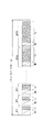
Images


Classifications
-
- G—PHYSICS
- G09—EDUCATION; CRYPTOGRAPHY; DISPLAY; ADVERTISING; SEALS
- G09G—ARRANGEMENTS OR CIRCUITS FOR CONTROL OF INDICATING DEVICES USING STATIC MEANS TO PRESENT VARIABLE INFORMATION
- G09G3/00—Control arrangements or circuits, of interest only in connection with visual indicators other than cathode-ray tubes
- G09G3/20—Control arrangements or circuits, of interest only in connection with visual indicators other than cathode-ray tubes for presentation of an assembly of a number of characters, e.g. a page, by composing the assembly by combination of individual elements arranged in a matrix no fixed position being assigned to or needed to be assigned to the individual characters or partial characters
- G09G3/2007—Display of intermediate tones
- G09G3/2018—Display of intermediate tones by time modulation using two or more time intervals
- G09G3/2022—Display of intermediate tones by time modulation using two or more time intervals using sub-frames
-
- G—PHYSICS
- G09—EDUCATION; CRYPTOGRAPHY; DISPLAY; ADVERTISING; SEALS
- G09G—ARRANGEMENTS OR CIRCUITS FOR CONTROL OF INDICATING DEVICES USING STATIC MEANS TO PRESENT VARIABLE INFORMATION
- G09G2320/00—Control of display operating conditions
- G09G2320/02—Improving the quality of display appearance
- G09G2320/0223—Compensation for problems related to R-C delay and attenuation in electrodes of matrix panels, e.g. in gate electrodes or on-substrate video signal electrodes
-
- G—PHYSICS
- G09—EDUCATION; CRYPTOGRAPHY; DISPLAY; ADVERTISING; SEALS
- G09G—ARRANGEMENTS OR CIRCUITS FOR CONTROL OF INDICATING DEVICES USING STATIC MEANS TO PRESENT VARIABLE INFORMATION
- G09G2320/00—Control of display operating conditions
- G09G2320/02—Improving the quality of display appearance
- G09G2320/0233—Improving the luminance or brightness uniformity across the screen
-
- G—PHYSICS
- G09—EDUCATION; CRYPTOGRAPHY; DISPLAY; ADVERTISING; SEALS
- G09G—ARRANGEMENTS OR CIRCUITS FOR CONTROL OF INDICATING DEVICES USING STATIC MEANS TO PRESENT VARIABLE INFORMATION
- G09G2320/00—Control of display operating conditions
- G09G2320/02—Improving the quality of display appearance
- G09G2320/0261—Improving the quality of display appearance in the context of movement of objects on the screen or movement of the observer relative to the screen
-
- G—PHYSICS
- G09—EDUCATION; CRYPTOGRAPHY; DISPLAY; ADVERTISING; SEALS
- G09G—ARRANGEMENTS OR CIRCUITS FOR CONTROL OF INDICATING DEVICES USING STATIC MEANS TO PRESENT VARIABLE INFORMATION
- G09G2320/00—Control of display operating conditions
- G09G2320/02—Improving the quality of display appearance
- G09G2320/0271—Adjustment of the gradation levels within the range of the gradation scale, e.g. by redistribution or clipping
-
- G—PHYSICS
- G09—EDUCATION; CRYPTOGRAPHY; DISPLAY; ADVERTISING; SEALS
- G09G—ARRANGEMENTS OR CIRCUITS FOR CONTROL OF INDICATING DEVICES USING STATIC MEANS TO PRESENT VARIABLE INFORMATION
- G09G2320/00—Control of display operating conditions
- G09G2320/06—Adjustment of display parameters
- G09G2320/0606—Manual adjustment
-
- G—PHYSICS
- G09—EDUCATION; CRYPTOGRAPHY; DISPLAY; ADVERTISING; SEALS
- G09G—ARRANGEMENTS OR CIRCUITS FOR CONTROL OF INDICATING DEVICES USING STATIC MEANS TO PRESENT VARIABLE INFORMATION
- G09G2320/00—Control of display operating conditions
- G09G2320/06—Adjustment of display parameters
- G09G2320/0626—Adjustment of display parameters for control of overall brightness
-
- G—PHYSICS
- G09—EDUCATION; CRYPTOGRAPHY; DISPLAY; ADVERTISING; SEALS
- G09G—ARRANGEMENTS OR CIRCUITS FOR CONTROL OF INDICATING DEVICES USING STATIC MEANS TO PRESENT VARIABLE INFORMATION
- G09G2360/00—Aspects of the architecture of display systems
- G09G2360/16—Calculation or use of calculated indices related to luminance levels in display data
-
- G—PHYSICS
- G09—EDUCATION; CRYPTOGRAPHY; DISPLAY; ADVERTISING; SEALS
- G09G—ARRANGEMENTS OR CIRCUITS FOR CONTROL OF INDICATING DEVICES USING STATIC MEANS TO PRESENT VARIABLE INFORMATION
- G09G3/00—Control arrangements or circuits, of interest only in connection with visual indicators other than cathode-ray tubes
- G09G3/20—Control arrangements or circuits, of interest only in connection with visual indicators other than cathode-ray tubes for presentation of an assembly of a number of characters, e.g. a page, by composing the assembly by combination of individual elements arranged in a matrix no fixed position being assigned to or needed to be assigned to the individual characters or partial characters
- G09G3/22—Control arrangements or circuits, of interest only in connection with visual indicators other than cathode-ray tubes for presentation of an assembly of a number of characters, e.g. a page, by composing the assembly by combination of individual elements arranged in a matrix no fixed position being assigned to or needed to be assigned to the individual characters or partial characters using controlled light sources
- G09G3/28—Control arrangements or circuits, of interest only in connection with visual indicators other than cathode-ray tubes for presentation of an assembly of a number of characters, e.g. a page, by composing the assembly by combination of individual elements arranged in a matrix no fixed position being assigned to or needed to be assigned to the individual characters or partial characters using controlled light sources using luminous gas-discharge panels, e.g. plasma panels
- G09G3/288—Control arrangements or circuits, of interest only in connection with visual indicators other than cathode-ray tubes for presentation of an assembly of a number of characters, e.g. a page, by composing the assembly by combination of individual elements arranged in a matrix no fixed position being assigned to or needed to be assigned to the individual characters or partial characters using controlled light sources using luminous gas-discharge panels, e.g. plasma panels using AC panels
Abstract
Description
本発明は、表示パネルを搭載した表示装置に関する。 The present invention relates to a display device equipped with a display panel.
現在、大型で薄型のカラー表示パネルとしてプラズマディスプレイパネル(以下、PDPと称する)を搭載したプラズマディスプレイ装置が製品化されている。 Currently, a plasma display device on which a plasma display panel (hereinafter referred to as PDP) is mounted as a large and thin color display panel has been commercialized.
PDPには、表示面を担う前面ガラス基板と、背面基板とが、放電ガスの封入された放電空間を介して対向配置されている。前面ガラス基板の内面(背面基板と対向する面)には表示面における行方向に伸長する帯状の行電極が複数個形成されている。一方、背面基板には表示面における列方向に伸長する帯状の列電極が複数個形成されている。この際、互いに隣接する一対の行電極(以下、行電極対と称する)が1表示ラインを担う。各行電極対と列電極との交叉部に画素を担う放電セルが形成される構造となっている。 In the PDP, a front glass substrate serving as a display surface and a rear substrate are disposed to face each other through a discharge space in which a discharge gas is sealed. A plurality of strip-like row electrodes extending in the row direction on the display surface are formed on the inner surface of the front glass substrate (the surface facing the rear substrate). On the other hand, a plurality of strip-like column electrodes extending in the column direction on the display surface are formed on the rear substrate. At this time, a pair of adjacent row electrodes (hereinafter referred to as a row electrode pair) serves as one display line. A discharge cell that carries a pixel is formed at the intersection of each row electrode pair and the column electrode.
プラズマディスプレイ装置では、先ず、各画素毎の画素データに応じて、放電セル各々内に選択的に壁電荷を形成させる。そして、PDPの行電極に維持パルスを繰り返し印加することにより、壁電荷の形成された放電セルに対して繰り返し維持放電を生起させてその放電に伴う発光状態を維持させるのである。 In the plasma display device, first, wall charges are selectively formed in each discharge cell in accordance with pixel data for each pixel. Then, by repeatedly applying a sustain pulse to the row electrode of the PDP, a sustain discharge is repeatedly generated in the discharge cells in which wall charges are formed, and the light emission state associated with the discharge is maintained.
ここで、上記維持放電に伴い、各行電極上には維持放電電流が流れる。又、PDPが大画面化するほど行電極も長くなり、その抵抗値も大となるので、上記維持放電電流が行電極に流れた際に比較的大なる電圧降下が生じる。この際、維持放電電流の電流量及び電圧降下は、その行電極上において維持放電の生起された放電セルの総数により各行電極毎に異なってくる。すなわち、維持放電の生起された放電セルの数が多い表示ラインは、その数が少ない表示ラインに比して電圧降下が大となるので、維持放電に伴う発光輝度が低下する。よって、1画面内において輝度ムラが生じるという問題があった。 Here, with the sustain discharge, a sustain discharge current flows on each row electrode. Further, the larger the screen of the PDP, the longer the row electrode and the larger the resistance value thereof, so that a relatively large voltage drop occurs when the sustain discharge current flows through the row electrode. At this time, the current amount and the voltage drop of the sustain discharge current are different for each row electrode depending on the total number of discharge cells in which the sustain discharge is generated on the row electrode. That is, a display line with a large number of discharge cells in which a sustain discharge has occurred has a large voltage drop compared to a display line with a small number of discharge cells, so that the light emission luminance associated with the sustain discharge decreases. Therefore, there is a problem that uneven brightness occurs in one screen.
そこで、かかる問題を解決すべく、表示データに基づき、各表示ライン毎にその表示ラインに印加すべき維持パルスの数を変更するようにした画像表示装置が提案された(例えば、特許文献1参照)。 Therefore, in order to solve such a problem, an image display device has been proposed in which the number of sustain pulses to be applied to each display line is changed for each display line based on display data (see, for example, Patent Document 1). ).
しかしながら、各表示ライン毎に維持パルスの数を変更するには複雑な制御が必要となり、又、その調整及び検証作業も困難になるという問題が生じる。
本発明は、かかる問題を解決すべく為されたものであり、簡略化された構成で輝度むらのない高品質な画像表示が可能な表示装置を提供することを目的とするものである。 The present invention has been made to solve such a problem, and an object of the present invention is to provide a display device capable of displaying a high-quality image without luminance unevenness with a simplified configuration.
請求項1記載による表示装置は、複数の表示ライン各々上に画素に対応した複数の画素セルが形成されている表示パネルと、映像信号に応じて前記表示ライン各々に駆動パルスを印加することにより前記画素セル各々を発光させる発光駆動手段とを備えた表示装置であって、前記映像信号に基づき1表示ライン上における前記画素セル各々の発光状態に対応した負荷量を前記表示ライン毎に測定する負荷量測定手段と、前記表示ライン各々に対応した前記映像信号の区間に対して、その表示ラインに対応した前記負荷量に応じた輝度レベルの補正を施す補正手段と、を有する。
The display device according to
又、請求項9記載による表示装置は、複数の表示ライン各々上に画素に対応した複数の画素セルが形成されている表示パネルと、映像信号に応じて前記表示ライン各々に駆動パルスを印加することにより前記画素セル各々を発光させる発光駆動手段とを備えた表示装置であって、前記映像信号に基づき前記画素セル各々の発光状態に対応した負荷量を前記画素セル毎に測定する負荷量測定手段と、前記表示ライン各々に対応した前記映像信号の区間に対して、その画素セルに対応した前記負荷量に応じた輝度レベルの補正を施す補正手段と、を有する。 According to a ninth aspect of the present invention, there is provided a display device in which a plurality of pixel cells corresponding to pixels are formed on each of the plurality of display lines, and a driving pulse is applied to each of the display lines in accordance with a video signal. A display device comprising: a light emission driving means for causing each pixel cell to emit light, and measuring a load amount corresponding to the light emission state of each pixel cell based on the video signal for each pixel cell And correction means for correcting the luminance level corresponding to the load amount corresponding to the pixel cell for the section of the video signal corresponding to each of the display lines.
又、請求項11記載による表示装置は、複数の表示ライン各々上に画素に対応した複数の画素セルが形成されている表示パネルと、映像信号に応じて前記表示ライン各々に駆動パルスを印加することにより前記画素セル各々を発光させる発光駆動手段とを備えた表示装置であって、前記映像信号に基づき前記画素セル各々の発光状態に対応した負荷量を測定する負荷量測定手段と、前記映像信号中にオンスクリーン画像信号が重畳されている場合又は前記映像信号がコンピュータ映像信号である場合に、前記負荷量に応じて前記映像信号における輝度レベルを補正する補正手段と、を有する。 The display device according to claim 11 applies a drive pulse to each display line according to a video signal and a display panel in which a plurality of pixel cells corresponding to pixels are formed on each of the plurality of display lines. A display device comprising: a light emission driving unit that causes each of the pixel cells to emit light, wherein a load amount measuring unit that measures a load amount corresponding to a light emission state of each of the pixel cells based on the video signal; and the video Correction means for correcting a luminance level in the video signal according to the load amount when an on-screen image signal is superimposed on the signal or when the video signal is a computer video signal.
映像信号に基づき表示ライン上における画素セル各々の発光状態に対応した負荷量を各表示ライン毎に測定し、各表示ラインに対応した映像信号の区間に対して、その表示ラインに対応した上記負荷量に応じた輝度レベルの補正を行う。 The load corresponding to the light emission state of each pixel cell on the display line is measured for each display line based on the video signal, and the load corresponding to the display line for the section of the video signal corresponding to each display line The brightness level is corrected according to the amount.
図1は、本発明による表示装置としてのプラズマディスプレイ装置の構成を示す図である。 FIG. 1 is a diagram showing a configuration of a plasma display device as a display device according to the present invention.
図1に示すように、かかるプラズマディスプレイ装置は、表示部1と、映像信号処理部2とから構成される。表示部1は、プラズマディスプレイパネルとしてのPDP10、X電極ドライバ11、Y電極ドライバ12、アドレスドライバ13、及び発光駆動制御回路14から構成される。
As shown in FIG. 1, the plasma display apparatus includes a
PDP100には、表示画面における垂直方向に夫々伸張している列電極D1〜Dmが形成されている。更に、PDP10には、表示画面における水平方向に夫々伸張している行電極X1〜Xn及び行電極Y1〜Ynが、XY交互に配列して形成されている。この際、互いに隣接するもの同士にて対を為す行電極対(Y1,X1)、(Y2,X2)、(Y3,X3)、・・・、(Yn,Xn)が夫々、PDP10における第1表示ライン〜第n表示ラインを担う。各表示ラインと列電極D1〜Dm各々との各交叉部には、画素を担う画素セルPCが形成されている。すなわち、PDP10には、第1表示ラインに属する画素セルPC1、1〜PC1、m、第2表示ラインに属する画素セルPC2、1〜PC2、m、・・・・、第n表示ラインに属する画素セルPCn、1〜PCn、mの各々がマトリクス状に配列されているのである。
The PDP 100 is formed with column electrodes D 1 to D m extending in the vertical direction on the display screen. Furthermore, the
発光駆動制御回路14は、例えば図2に示す如きサブフィールド法を採用した発光駆動シーケンスに従ってPDP10を発光駆動させるべく、映像信号VSに応じて、X電極ドライバ11、Y電極ドライバ12及びアドレスデータドライバ13各々を制御する。尚、図2に示す発光駆動シーケンスでは、映像信号の各フィールド(又はフレーム)は、夫々がアドレス行程Wc及び発光維持行程Icを含む15個のサブフィールドSF1〜SF15からなる。
For example, the light emission
サブフィールドSF1〜SF15各々のアドレス行程Wcでは、Y電極ドライバ12が、行電極Y1〜行電極Ynへと順次、走査パルスSPを印加して行く。この間、アドレスデータドライバ13は、メモリ31から供給された1表示ライン分の画素駆動データビットDB1〜DBm各々に対応した電圧を有するm個の画素データパルスDP1〜DPmを夫々PDP10の列電極D1〜Dmに印加する。かかる動作により、PDP10の画素セルPC1、1〜PCn、m各々が、画素駆動データビットDBに応じて、発光維持行程Icで発光することになる発光モード、又は発光維持行程Icにおいて消灯状態となる消灯モードのいずれか一方に設定される。
In the subfields SF1~SF15 each address step Wc,
又、サブフィールドSF1〜SF15各々の発光維持行程Icにおいては、X電極ドライバ11が、そのサブフィールドSFの重み付けに対応した回数だけ繰り返し維持パルスをPDP10の行電極X1〜Xn各々に印加する。更に、Y電極ドライバ12は、サブフィールドSF1〜SF15各々の発光維持行程Icにおいて、そのサブフィールドの重み付けに対応した回数だけ繰り返し維持パルスをPDP10の行電極Y1〜Yn各々に印加する。かかる動作により、PDP10の画素セルPC1、1〜PCn、m各々の内で上記発光モードに設定されている画素セルPCのみが、上記維持パルスが印加される度に放電(維持放電)し、その放電に伴う発光状態を維持する。
Further, in the subfield SF1~SF15 each light emission sustain process Ic is, X electrode driver 11, the number of times repetitive sustain pulses corresponding to the weighting of the subfield SF is applied to the row electrodes X 1 to X n each PDP10 . Further, the
以上の如き動作により、サブフィールドSF1〜SF15各々の発光維持行程Icにて画素セルPCが維持放電した合計回数に対応した中間輝度が視覚されることになる。 Through the above operation, intermediate luminance corresponding to the total number of times that the pixel cell PC has been sustained and discharged in the light emission sustaining process Ic of each of the subfields SF1 to SF15 is visually recognized.
又、図1において、映像信号処理部2は、入力セレクタ21、表示制御回路22、加算器23、OSD(On Screen Display)画像信号生成回路24、スイッチ25、操作装置26、APL検出回路27、輝度調整回路28、輝度補正回路29、画素駆動データ生成回路30及びメモリ31から構成される。
1, the video
入力セレクタ21は、入力されたテレビジョン映像信号(以下、TV映像信号と称する)、又はコンピュータ映像信号(以下、PC映像信号と称する)の内のいずれか一方を、表示制御回路22から供給された選択信号Sに応じて選択し、これを加算器23に供給する。OSD画像信号生成回路24は、表示制御回路22にて指定された操作用画像に対応したOSD画像信号(オンスクリーン画像信号)を生成し、これをスイッチ25に供給する。スイッチ25は、表示制御回路22からOSD画像表示指令信号OSが供給された場合にオン状態となり、上記OSD画像信号を加算器23に供給する。加算器23は、入力セレクタ21から供給された映像信号(TV映像信号又はPC映像信号)に、上記スイッチ25から供給されたOSD画像信号を加算して得られた映像信号VSを発光駆動制御回路14、APL検出回路27、及び輝度調整回路28に供給する。
The input selector 21 is supplied from the
操作装置26は、使用者の操作を受付その操作に対応した各種指令信号を発生する。例えば、使用者によってテレビジョン映像を表示させるべき操作が為されると、操作装置26は、テレビジョン映像表示指令信号を表示制御回路22に供給する。この際、表示制御回路22は、TV映像信号を選択させるべき選択信号Sを入力セレクタ21に供給する。又、使用者によってコンピュータ映像を表示させるべき操作が為されると、操作装置26は、コンピュータ映像表示指令信号を表示制御回路22に供給する。この際、表示制御回路22は、PC映像信号を選択させるべき選択信号Sを入力セレクタ21に供給する。又、操作装置26は、使用者によって例えば画面サイズ切替操作キー(図示せぬ)が押圧されたら、画面サイズ切替操作用のOSD画像信号を生成させるべき指令を表示制御回路22に供給すると共に、OSD画像表示指令信号OSをスイッチ25に供給する。これにより、加算器23は、入力セレクタ21にて選択された映像信号(TV映像信号又はPC映像信号)に、例えば画面サイズ切替操作用のOSD画像信号を重畳して得た映像信号VSを出力する。尚、使用者が、OSD画像を表示させるべき指令操作を行わなかった場合にはスイッチ25がオフ状態となるので、この際、加算器23は、入力セレクタ21にて選択された映像信号をそのまま映像信号VSとして出力する。APL検出回路27は、かかる映像信号VSにおける平均輝度レベルを1フィールド(フレーム)毎に求め、これを平均輝度レベルAPLとして輝度調整回路28に供給する。輝度調整回路28は、平均輝度レベルAPLが大なるほど大なる低下率にて、映像信号VSの輝度レベルを低下させるべき調整をかかる映像信号VSに対して施して得られた輝度調整映像信号VSCを輝度補正回路29に供給する。
The
輝度補正回路29は、1表示ライン上において発光状態となる画素セルの総数に応じた負荷量が各表示ライン毎に異なることに起因する輝度ムラを補正すべく、輝度調整映像信号VSCに対して輝度レベルの補正処理(後述する)を施し、得られた輝度補正映像信号VCを画素駆動データ生成回路30に供給する。
画素駆動データ生成回路30は、輝度補正映像信号VCに基づき、図2に示すサブフィールドSF1〜SF15各々のアドレス行程Wcにおいて各画素セルPC1、1〜PCn、mを発光モード又は消灯モードのいずれの状態に設定するのかを指定する画素駆動データGD1、1〜GDn、mを生成してメモリ31に供給する。尚、画素駆動データGD1、1〜GDn、mの各々は、サブフィールドSF1〜SF15各々に対応した15ビットからなる。例えば、画素セルPC1、1に対応した画素駆動データGD1、1の第1ビットが論理レベル1である場合には、サブフィールドSF1のアドレス行程Wcにおいて画素セルPC1、1が発光モードに設定されることになる。一方、画素駆動データGD1、1の第1ビットが論理レベル0である場合には、サブフィールドSF1のアドレス行程Wcにおいて画素セルPC1、1が消灯モードに設定されることになる。又、画素駆動データGD1、1の第15ビットが論理レベル1である場合にはサブフィールドSF15のアドレス行程Wcにて画素セルPC1、1が発光モードに設定される一方、その第15ビットが論理レベル0である場合にはSF15のアドレス行程Wcにて画素セルPC1、1が消灯モードに設定されることになる。
Pixel drive
メモリ31は、画素駆動データ生成回路30から供給された画素駆動データGD1、1〜GDn、mを記憶し、これらを夫々同一ビット桁同士にて分離して読み出す。すなわち、メモリ31は、記憶された各画素セルPC毎の画素駆動データGDを、
DB1:画素駆動データGDの第1ビット
DB2:画素駆動データGDの第2ビット
DB3:画素駆動データGDの第3ビット
DB4:画素駆動データGDの第4ビット
DB5:画素駆動データGDの第5ビット
DB6:画素駆動データGDの第6ビット
DB7:画素駆動データGDの第7ビット
DB8:画素駆動データGDの第8ビット
DB9:画素駆動データGDの第9ビット
DB10:画素駆動データGDの第10ビット
DB11:画素駆動データGDの第11ビット
DB12:画素駆動データGDの第12ビット
DB13:画素駆動データGDの第13ビット
DB14:画素駆動データGDの第14ビット
DB15:画素駆動データGDの第15ビット
なる画素駆動データビットDB1〜DB15として読み出す。
DB1: First bit of pixel drive data GD
DB2: Second bit of pixel drive data GD
DB3: Third bit of pixel drive data GD
DB4: 4th bit of pixel drive data GD
DB5: 5th bit of pixel drive data GD
DB6: 6th bit of pixel drive data GD
DB7: 7th bit of pixel drive data GD
DB8: 8th bit of pixel drive data GD
DB9: 9th bit of pixel drive data GD
DB10: 10th bit of pixel drive data GD
DB11: 11th bit of pixel drive data GD
DB12: 12th bit of pixel drive data GD
DB13: 13th bit of pixel drive data GD
DB14: 14th bit of pixel drive data GD
DB15: Read out as pixel drive data bits DB1 to DB15 which are the 15th bit of the pixel drive data GD.
この際、メモリ31は、
画素駆動データビットDB1をサブフィールドSF1、
画素駆動データビットDB2をサブフィールドSF2、
画素駆動データビットDB3をサブフィールドSF3、
画素駆動データビットDB4をサブフィールドSF4、
画素駆動データビットDB5をサブフィールドSF5、
画素駆動データビットDB6をサブフィールドSF6、
画素駆動データビットDB7をサブフィールドSF7、
画素駆動データビットDB8をサブフィールドSF8、
画素駆動データビットDB9をサブフィールドSF9、
画素駆動データビットDB10をサブフィールドSF10、
画素駆動データビットDB11をサブフィールドSF11、
画素駆動データビットDB12をサブフィールドSF12、
画素駆動データビットDB13をサブフィールドSF13、
画素駆動データビットDB14をサブフィールドSF14、
画素駆動データビットDB15をサブフィールドSF15、
各々のアドレス行程Wcの実行時において読み出して、アドレスデータドライバ13に供給する。
At this time, the
The pixel drive data bit DB1 is subfield SF1,
The pixel drive data bit DB2 is subfield SF2,
The pixel drive data bit DB3 is subfield SF3,
The pixel drive data bit DB4 is changed to subfield SF4,
The pixel drive data bit DB5 is changed to subfield SF5,
The pixel drive data bit DB6 is changed to subfield SF6,
The pixel drive data bit DB7 is subfield SF7,
The pixel drive data bit DB8 is converted into a subfield SF8,
The pixel drive data bit DB9 is changed to subfield SF9,
The pixel drive data bit DB10 is subfield SF10,
The pixel drive data bit DB11 is changed to the subfield SF11,
The pixel drive data bit DB12 is subfield SF12,
The pixel drive data bit DB13 is converted into a subfield SF13,
The pixel drive data bit DB14 is converted into a subfield SF14,
The pixel drive data bit DB15 is changed to the subfield SF15,
Read out at the time of execution of each address step Wc and supply it to the
次に、図1に示される輝度補正回路29による輝度補正処理動作について説明する。
Next, the luminance correction processing operation by the
図3は、輝度補正回路29の内部構成を示す図である。
FIG. 3 is a diagram showing an internal configuration of the
図3において、画素駆動データ生成回路291は、先ず、上記輝度調整映像信号VSCを1表示ライン分毎に、その表示ライン内のm個の画素に夫々対応した画素データPD1〜PDmに変換する。次に、画素駆動データ生成回路291は、かかる画素データPD1〜PDmに基づき、サブフィールドSF1〜SF15各々のアドレス行程Wcで画素セルPCの設定状態(発光又は消灯モード)を指定する為の夫々15ビットからなる画素駆動データGDD1〜GDDmを生成する。例えば、第1表示ラインに対応した画素駆動データGDD1の第1ビットが論理レベル1である場合には、サブフィールドSF1のアドレス行程Wcにおいて画素セルPC1、1が発光モードに設定されることになる。一方、画素駆動データGD1の第1ビットが論理レベル0である場合には、サブフィールドSF1のアドレス行程Wcにおいて画素セルPC1、1は消灯モードに設定されることになる。又、第1表示ラインに対応した画素駆動データGDD2の第3ビットが論理レベル1である場合には、サブフィールドSF3のアドレス行程Wcにおいて画素セルPC1、2が発光モードに設定されることになる。
3, the pixel drive
発光セル数測定回路292は、1表示ライン分の画素駆動データGDD1〜GDDmに基づき、各サブフィールドSF1〜SF15毎に、発光モードに設定されることになる画素セルPCの数を発光セル数LNとして求める。そして、発光セル数測定回路292は、サブフィールドSF1〜SF15各々毎の発光セル数LN1〜LN15をSF補正係数算出回路293に供給する。
The light emitting cell
SF補正係数算出回路293は、
SG=1−α・[(m−LN)/m]2
α:所定係数
m:1表示ラインに属する画素セルPCの総数
LN:1表示ライン内での発光セル数
なる数式にて、サブフィールドSF1〜SF15各々に対応したSF補正係数SG1〜SG15を求めて、画素補正係数算出回路294に供給する。
The SF correction
SG = 1−α · [(m−LN) / m] 2
α: Predetermined coefficient
m: Total number of pixel cells PC belonging to one display line
LN: SF correction coefficients SG1 to SG15 corresponding to each of the subfields SF1 to SF15 are calculated by the following formula and supplied to the pixel correction
画素補正係数算出回路294は、上記SF補正係数SG1〜SG15、サブフィールドSF1〜SF15各々の発光維持行程Icでの発光回数K1〜K15、及び画素駆動データGDD1〜GDDm各々の第1ビットB1〜第15ビットB15に基づき、1表示ライン分のm個の画素各々に対応した、
(数式1)
GQ=[(SG1・K1・B1Q)+(SG2・K2・B2Q)+(SG3・K3・B3Q)+、・・・、+(SG15・K15・B15Q)]
/[(K1・B1Q)+(K2・B2Q)+(K3・B3Q)+、・・・、+(K15・B15Q)]
Q:1,2,3,・・・,m
なる画素補正係数G1〜Gmを算出し、これらをG1、G2、G3、・・・、Gmなる順に乗算器295に供給して行く。
The pixel correction
(Formula 1)
G Q = [(SG1, K1, B1 Q ) + (SG2, K2, B2 Q ) + (SG3, K3, B3 Q ) +, ..., + (SG15, K15, B15 Q )]
/ [(K1 / B1 Q ) + (K2 / B2 Q ) + (K3 / B3 Q ) +, ..., + (K15 / B15 Q )]
Q: 1,2,3, ..., m
Calculating a composed pixel correction coefficient G 1 ~G m, these G 1, G 2, G 3 , ···, go supplied to the
1表示ライン遅延メモリ296は、輝度調整回路28から供給された輝度調整映像信号VSCを1表示ライン分だけ遅延させてから、順次、乗算器295に送出する。乗算器295は、1表示ライン遅延メモリ296から順次供給される輝度調整映像信号VSCによって示される輝度レベルに、画素補正係数G1、G2、G3、・・・、Gmを順次乗算し、その乗算結果を輝度補正映像信号VCとして出力する。すなわち、乗算器295は、輝度調整映像信号VSCにおける各画素に対応した区間に対し、その画素に対応した画素補正係数G1、G2、G3、・・・、Gmを順次乗算することにより輝度レベルの補正を行うのである。
1 display
以上の如く、輝度補正回路29においては、先ず、サブフィールドSF1〜SF15各々毎に、各表示ライン内で発光モードに設定される画素セルPCの数に対応したSF補正係数SG1〜SG15を求める。次に、上記数式1の分子項にて示されるように、SF補正係数SG1〜SG15各々に対して、各サブフィールドの発光回数K1〜K15による重みを付加して重み付け加算を実施する。この際、各画素毎にその画素に対応した画素駆動データGDD(B1〜B15)に基づき、重み付け加算の対象とするSF補正係数SGを決定する。すなわち、画素駆動データGDDのビットが、画素セルPCを発光モードに設定することになる論理レベル1である場合に限り、そのビット桁に対応したサブフィールドSFのSF補正係数SGが重み付け加算の対象となるのである。つまり、消灯モードに設定することになる論理レベル0のビット桁に対応したサブフィールドSFのSF補正係数SGは、上記の如き重み付け加算の対象外となる。そして、輝度補正回路29は、上記数式1にて示されるように、この重み付け加算結果を、上記画素駆動データGDDに基づく1フィールド内での総発光回数で除算することにより、各画素毎の画素補正係数Gを求めるのである。
As described above, in the
例えば、画素駆動データGDDの第1ビットB1〜第3ビットB3が論理レベル1、第4ビットB4〜第15ビットB15が論理レベル0である場合には、SF1〜SF3各々に対応したSF補正係数SG1〜SG3のみが上記の如き重み付け加算の対象となる。更に、この際、1フィールド内においてSF1〜SF3各々の発光維持行程Icのみで画素セルPCの発光が為されるので、その総発光回数はK1+K2+K3となる。よって、この際、得られる画素補正係数Gは、
G=[(SG1・K1)+(SG2・K2)+(SG3・K3)]/[K1+K2+K3]
となる。
For example, when the first bit B1 to the third bit B3 of the pixel drive data GDD are the
G = [(SG1 ・ K1) + (SG2 ・ K2) + (SG3 ・ K3)] / [K1 + K2 + K3]
It becomes.
そして、輝度補正回路29は、各画素毎の画素補正係数Gを輝度調整映像信号VSCに乗算することにより、輝度補正の施された輝度補正映像信号VCを生成するのである。
The
ここで、各表示ライン内のm個の画素セルPCが全てサブフィールドSF1〜SF15に亘り発光モードに設定される場合には、上記発光セル数LN1〜LN15がいずれもm個となる。よって、上記SF補正係数SG1〜SG15が全て1となり、画素補正係数Gが1となる。すなわち、各表示ライン内のm個の画素セルPCの全てがサブフィールドSF1〜SF15に亘り発光モードに設定される、いわゆる負荷量が最大となる場合には、輝度調整映像信号VSCがそのまま輝度補正映像信号VCとして出力される。一方、各表示ライン内に消灯モードに設定される画素セルPCが存在する場合には、その数の分だけSF補正係数SGが小となり、画素補正係数Gが小(1以下)となる。 Here, when all the m pixel cells PC in each display line are set to the light emission mode over the subfields SF1 to SF15, the number of the light emitting cells LN1 to LN15 is m. Therefore, the SF correction coefficients SG1 to SG15 are all 1 and the pixel correction coefficient G is 1. That is, all m pixel cells PC in the respective display lines are set to the light emitting mode over the sub-fields SF1-SF15, if the so-called load is maximum, the luminance adjustment video signal VS C is directly brightness The corrected video signal VC is output. On the other hand, when there is a pixel cell PC set in the extinguishing mode in each display line, the SF correction coefficient SG is decreased by the number of pixels, and the pixel correction coefficient G is decreased (1 or less).
すなわち、輝度補正回路29においては、発光状態(又は消灯状態)となる画素セルPCの数を各表示ライン毎に測定することにより表示ライン毎の負荷量を求め、この負荷量に応じて、その表示ラインに属する画素セル各々に対応した輝度調整映像信号VSCの輝度レベルを補正するのである。この際、各表示ライン上において発光状態となる画素セルPCの数が少なくなるほど、その表示ラインでの電流消費量が減って電圧降下も小さくなるので、発光状態となる画素セルPCの数(各表示ライン上での)が少ないほど、輝度調整映像信号VSCの輝度レベルを低下させるべき補正を行うのである。かかる補正動作により、発光状態となる画素セル数が多い為に電圧降下が大となる表示ラインと、発光状態となる画素セル数が少ないが故に電圧降下が小となる表示ラインとの間における画素セル同士の輝度差が低減されるのである。
That is, in the
よって、図3に示す輝度補正回路29によれば、PDP10に印加すべき維持パルスの数を各表示ライン毎に変更するような複雑な制御を行うことなく、表示ライン間での輝度差を低減させることが可能になる。
Therefore, according to the
尚、上記実施例においては、輝度補正回路29は、1表示ライン上の画素セルPCが全て発光状態にある場合を基準(画素補正係数G=1)にして輝度補正を行っているが、1表示ライン上の画素セルPCが全て消灯状態にある場合を基準にして輝度補正を行うようにしても良い。
In the above embodiment, the
すなわち、この際、輝度補正回路29のSF補正係数算出回路293は、
SG=1+α・[LN/m]2
α:所定係数
m:1表示ライン上の画素セルPCの総数
LN:1表示ライン内での発光セル数
なる数式にて、lサブフィールドSF1〜SF15各々に対応したSF補正係数SG1〜SG15を求める。これにより、各表示ライン内のm個の画素セルPCが全てサブフィールドSF1〜SF15に亘り消灯モードに設定される場合には、上記発光セル数LN1〜LN15がいずれも0個となる。よって、上記SF補正係数SG1〜SG15が全て1となり、画素補正係数Gが1となる。すなわち、各表示ライン内のm個の画素セルPCの全てがサブフィールドSF1〜SF15に亘り消灯状態となる、いわゆる負荷量が最小となる場合には、輝度調整映像信号VSCがそのまま輝度補正映像信号VCとして出力される。一方、各表示ライン内に発光モードに設定される画素セルPCが存在する場合には、その数の分だけSF補正係数SGが大となり、画素補正係数Gが大(1以上)となる。つまり、輝度補正回路29は、各表示ライン内において発光状態となる画素セルPCの数が多いほど、輝度調整映像信号VSCのレベルを増加させるべき補正を行うのである。
That is, at this time, the SF correction
SG = 1 + α · [LN / m] 2
α: Predetermined coefficient
m: Total number of pixel cells PC on one display line
LN: SF correction coefficients SG1 to SG15 corresponding to each of the 1 subfields SF1 to SF15 are obtained by the following formula. Thereby, when all the m pixel cells PC in each display line are set to the light-off mode over the subfields SF1 to SF15, the number of light emitting cells LN1 to LN15 is all zero. Therefore, the SF correction coefficients SG1 to SG15 are all 1 and the pixel correction coefficient G is 1. That is, all m pixel cells PC in each display line is turned off over the subfields SF1-SF15, if the so-called load becomes minimum, brightness adjustment video signal VS C is as luminance correction image Output as signal VC. On the other hand, when there is a pixel cell PC set in the light emission mode in each display line, the SF correction coefficient SG is increased by that number, and the pixel correction coefficient G is increased (1 or more). In other words, the
よって、かかる補正動作によっても、発光状態となる画素セルPCの数が多い為に電圧降下が大となる表示ラインと、発光状態となる画素セルPCの数が少ないが故に電圧降下が小となる表示ラインとの間における画素セル同士の輝度差を低減させることが可能になる。 Therefore, even with such a correction operation, the voltage drop is small because the number of pixel cells PC in the light emitting state is large and the voltage drop is large, and the number of pixel cells PC in the light emitting state is small. It is possible to reduce the luminance difference between the pixel cells with respect to the display line.
ここで、1画面内の平均輝度レベルが低い、いわゆる暗い画像を表示している場合には、明るい画像を表示している場合に比して表示ライン間での輝度差が目立ちにくい。 Here, when a so-called dark image with a low average luminance level in one screen is displayed, the luminance difference between display lines is less noticeable than when a bright image is displayed.
そこで、輝度補正回路29においては、1画面内の平均輝度レベル、つまりAPL検出回路27にて検出された平均輝度レベルAPLが所定レベルよりも低い場合には、高い場合に比して輝度調整映像信号VSCに対する補正量を低下するようにしても良い。この際、画素補正係数算出回路294は、平均輝度レベルAPLが所定値以下の場合には、上記数式1によって求めた画素補正係数Gに代わり、この画素補正係数Gに例えば下記の如き演算を施すことにより輝度調整映像信号VSCに対する補正量を低下させた画素補正係数GGを、乗算器295に供給する。
Therefore, in the
GG=P・G+Q
1=P+Q
P、Qは正の小数
又、画素補正係数算出回路294は、平均輝度レベルAPLが所定値以下の場合には、上記数式1によって求めた画素補正係数Gに代わり、補正量0となる「1」を乗算器295に固定供給するようにしても良い。
GG = P · G + Q
1 = P + Q
P and Q are positive decimal numbers. Further, when the average luminance level APL is equal to or less than a predetermined value, the pixel correction
同様に、入力映像信号がTV映像信号の如き動画像を表す動画像信号である場合には、入力映像信号中にOSD画像が重畳表示される場合、又は入力映像信号がPC映像信号である場合に比して表示ライン間での輝度差が目立ちにくい。 Similarly, when the input video signal is a moving image signal representing a moving image such as a TV video signal, an OSD image is superimposed on the input video signal, or the input video signal is a PC video signal Compared to the above, the luminance difference between display lines is less noticeable.
そこで、画素補正係数算出回路294は、OSD画像表示指令信号OSが供給されていない場合、又は選択信号SがTV映像信号の選択を示す場合には、上記数式1にて求めた画素補正係数Gに代わり、この画素補正係数Gよりも輝度調整映像信号VSCに対する補正量が小なる上記画素補正係数GGを、乗算器295に供給する。又、画素補正係数算出回路294は、OSD画像表示指令信号OSが供給されていない場合、又は選択信号SがTV映像信号の選択を示す場合には、上記数式1によって求めた画素補正係数Gに代わり、補正量0となる「1」を乗算器295に固定供給するようにしても良い。
Therefore, when the OSD image display command signal OS is not supplied, or when the selection signal S indicates the selection of the TV video signal, the pixel correction
以上の如く、図3に示される輝度補正回路29においては、表示ライン上における画素セル各々の発光状態に基づいて各表示ライン毎に負荷量を測定し、映像信号における各表示ラインに対応した区間に対し、その表示ラインに対応した負荷量に応じた輝度レベルの補正を行うようにしている。
As described above, in the
ところで、各表示ライン内においても、発光状態となる画素セルPCの位置関係によって、その発光輝度に輝度差が生じる場合がある。例えば、表示ラインの中央部に対して左端又は右端に位置する画素セルPCほどその発光輝度が低くなる。 Incidentally, even in each display line, there may be a luminance difference in the light emission luminance depending on the positional relationship of the pixel cells PC in the light emitting state. For example, the pixel cell PC located at the left end or the right end with respect to the central portion of the display line has a lower emission luminance.
図4は、かかる点に鑑みて為された輝度補正回路29の他の内部構成を示す図である。
FIG. 4 is a diagram showing another internal configuration of the
尚、図4に示す輝度補正回路29においては、図3に示す発光セル数測定回路292及びSF補正係数算出回路293に代わり、発光セル間距離測定回路298及びSF補正係数生成回路299を採用したものであり、他の構成は図3に示すものと同一である。
4 employs a light emitting cell
図4において、発光セル間距離測定回路298は、各表示ライン毎の画素駆動データGDD1〜GDDmに基づき、各画素セル毎に、その画素セルの最近傍位置(1表示ライン内での)に存在する発光モード状態の画素セルまでの距離をサブフィールドSF1〜SF15各々毎に測定する。例えば、画素駆動データGDD1〜GDDmが図5の如き論理レベルを有する場合には、第1列目の画素セルは、画素駆動データGDD1の第1ビットB1が論理レベル1であることから、サブフィールドSF1において発光モードに設定される。この際、第1列目の画素セルに隣接する第2列目及び第3列目の画像セル各々に対応した画素駆動データGDD1の第2ビットB2及び第3ビットB3が共に論理レベル0であるが、第4列目の画像セルに対応した画素駆動データGDD1の第4ビットB4が論理レベル1である。つまり、サブフィールドSF1では、第1列目の画素セルの最近傍位置に存在する発光モード状態の画素セルは、第4列目の画素セルとなる。よって、サブフィールドSF1では、第1列目の画素セルに対して、この第1列目の画素セルから第4列目の画素セルまでの距離「3」が発光セル間距離測定回路298によって測定されることになる。又、サブフィールドSF1では、第2列目の画素セルに対して、最近傍位置に存在する発光モード状態の画素セルは第1列目の画素セルとなるので、この第2列目の画素セルから第1列目の画素セルまでの距離「1」が発光セル間距離測定回路298によって測定されることになる。又、サブフィールドSF2では、第1列目の画素セルに対して、最近傍位置に存在する発光モード状態の画素セルは第5列目の画素セルとなるので、この第1列目の画素セルから第5列目の画素セルまでの距離「4」が発光セル間距離測定回路298によって測定されることになる。
In FIG. 4, the
発光セル間距離測定回路298は、上述した如く、サブフィールドSF1〜SF15各々に対応させて各画素セル毎に、同一表示ライン内において最近傍位置に存在する発光画素セルまでの距離を測定し、この距離を示す発光セル間距離データLDをSF補正係数生成回路299に供給する。
As described above, the light emitting cell
SF補正係数生成回路299は、各画素セル毎に、サブフィールドSF1〜SF15各々に対応した上記発光セル間距離データLDに応じた値を有するSF補正係数SG1〜SG15を求めて画素補正係数算出回路294に供給する。
The SF correction
かかる構成により、図4に示される輝度補正回路29においては、各表示ライン内において発光状態となる画素セルの位置関係に基づいて、各画素毎にその画素に対応した映像信号を補正するようにしている。
With this configuration, the
よって、表示ライン間のみならず、表示ライン内においても各画素セル間の輝度差をなくすことが可能となる。 Therefore, it is possible to eliminate the luminance difference between the pixel cells not only between the display lines but also within the display lines.
10 PDP
29 輝度補正回路
291 画素駆動データ生成回路
292 発光セル数測定回路
293 SF補正係数算出回路
294 画素補正係数算出回路
295 乗算器
296 1表示ライン遅延メモリ
297 セル位置情報生成回路
298 位置係数生成回路
10 PDP
29 Brightness correction circuit
291 Pixel drive data generation circuit
292 Light emitting cell number measurement circuit
293 SF correction coefficient calculation circuit
294 Pixel correction coefficient calculation circuit
295 multiplier
296 1 display line delay memory
297 Cell position information generation circuit
298 Position coefficient generator
Claims (15)
前記映像信号に基づき1表示ライン上における前記画素セル各々の発光状態に対応した負荷量を前記表示ライン毎に測定する負荷量測定手段と、
前記表示ライン各々に対応した前記映像信号の区間に対して、その表示ラインに対応した前記負荷量に応じた輝度レベルの補正を施す補正手段と、
を有することを特徴とする表示装置。 A display panel in which a plurality of pixel cells corresponding to pixels are formed on each of the plurality of display lines, and light emission driving for causing each of the pixel cells to emit light by applying a driving pulse to each of the display lines in accordance with a video signal A display device comprising means,
Load amount measuring means for measuring, for each display line, a load amount corresponding to the light emission state of each of the pixel cells on one display line based on the video signal;
Correction means for correcting the luminance level corresponding to the load amount corresponding to the display line for the section of the video signal corresponding to each display line;
A display device comprising:
前記補正手段は、前記平均輝度レベルに応じて前記輝度レベルの補正量を変更することを特徴とする請求項1記載の表示装置。 An average luminance detecting means for detecting an average luminance level of the video signal;
The display device according to claim 1, wherein the correction unit changes a correction amount of the luminance level according to the average luminance level.
前記負荷量測定手段は、前記サブフィールド毎に前記表示ライン各々に対応した前記負荷量を求め、
前記補正手段は、前記サブフィールド各々に対応した前記負荷量を重み付け加算して得た加算結果に基づいて前記輝度レベルの補正量を算出することを特徴とする請求項1記載の表示装置。 The light emission drive means includes light emission drive control means for causing the pixel cells to emit light according to the video signal in each of a plurality of subfields constituting each field in the video signal,
The load amount measuring means obtains the load amount corresponding to each display line for each subfield,
The display device according to claim 1, wherein the correction unit calculates the correction amount of the luminance level based on an addition result obtained by weighted addition of the load amounts corresponding to the subfields.
前記映像信号に基づき前記画素セル各々の発光状態に対応した負荷量を前記画素セル毎に測定する負荷量測定手段と、
前記表示ライン各々に対応した前記映像信号の区間に対して、その画素セルに対応した前記負荷量に応じた輝度レベルの補正を施す補正手段と、を有することを特徴とする表示装置。 A display panel in which a plurality of pixel cells corresponding to pixels are formed on each of the plurality of display lines, and light emission driving for causing each of the pixel cells to emit light by applying a driving pulse to each of the display lines in accordance with a video signal A display device comprising means,
Load amount measuring means for measuring, for each pixel cell, a load amount corresponding to the light emission state of each of the pixel cells based on the video signal;
A display device, comprising: correction means for correcting a luminance level corresponding to the load amount corresponding to the pixel cell with respect to a section of the video signal corresponding to each display line.
前記補正手段は、前記平均輝度レベルに応じて前記輝度レベルの補正量を変更することを特徴とする請求項9記載の表示装置。 An average luminance detecting means for detecting an average luminance level of the video signal;
The display device according to claim 9, wherein the correction unit changes a correction amount of the luminance level according to the average luminance level.
前記映像信号に基づき前記画素セル各々の発光状態に対応した負荷量を測定する負荷量測定手段と、
前記映像信号中にオンスクリーン画像信号が重畳されている場合又は前記映像信号がコンピュータ映像信号である場合に、前記負荷量に応じて前記映像信号における輝度レベルを補正する補正手段と、を有することを特徴とする表示装置。 A display panel in which a plurality of pixel cells corresponding to pixels are formed on each of the plurality of display lines, and light emission driving for causing each of the pixel cells to emit light by applying a driving pulse to each of the display lines in accordance with a video signal A display device comprising means,
Load amount measuring means for measuring a load amount corresponding to the light emission state of each of the pixel cells based on the video signal;
Correction means for correcting a luminance level in the video signal according to the load amount when an on-screen image signal is superimposed on the video signal or when the video signal is a computer video signal. A display device.
前記補正手段は、前記平均輝度レベルに応じて前記輝度レベルの補正量を変更することを特徴とする請求項12記載の表示装置。
An average luminance detecting means for detecting an average luminance level of the video signal;
The display device according to claim 12, wherein the correction unit changes a correction amount of the luminance level according to the average luminance level.
Priority Applications (3)
| Application Number | Priority Date | Filing Date | Title |
|---|---|---|---|
| JP2004065578A JP2005257754A (en) | 2004-03-09 | 2004-03-09 | Display apparatus |
| US11/072,648 US7701415B2 (en) | 2004-03-09 | 2005-03-07 | Display device |
| EP05101817A EP1580716A3 (en) | 2004-03-09 | 2005-03-09 | Display device |
Applications Claiming Priority (1)
| Application Number | Priority Date | Filing Date | Title |
|---|---|---|---|
| JP2004065578A JP2005257754A (en) | 2004-03-09 | 2004-03-09 | Display apparatus |
Publications (1)
| Publication Number | Publication Date |
|---|---|
| JP2005257754A true JP2005257754A (en) | 2005-09-22 |
Family
ID=34858328
Family Applications (1)
| Application Number | Title | Priority Date | Filing Date |
|---|---|---|---|
| JP2004065578A Pending JP2005257754A (en) | 2004-03-09 | 2004-03-09 | Display apparatus |
Country Status (3)
| Country | Link |
|---|---|
| US (1) | US7701415B2 (en) |
| EP (1) | EP1580716A3 (en) |
| JP (1) | JP2005257754A (en) |
Cited By (8)
| Publication number | Priority date | Publication date | Assignee | Title |
|---|---|---|---|---|
| KR100805105B1 (en) | 2006-02-28 | 2008-02-21 | 삼성에스디아이 주식회사 | Plasma display and driving method thereof |
| KR100863964B1 (en) | 2007-04-12 | 2008-10-16 | 삼성에스디아이 주식회사 | Plasma display and driving method thereof |
| WO2009139152A1 (en) * | 2008-05-14 | 2009-11-19 | パナソニック株式会社 | Plasma display device and method for driving plasma display panel |
| WO2010055644A1 (en) * | 2008-11-12 | 2010-05-20 | パナソニック株式会社 | Plasma display device and plasma display panel driving method |
| WO2010055661A1 (en) * | 2008-11-13 | 2010-05-20 | パナソニック株式会社 | Plasma display device and plasma display panel driving method |
| WO2010055662A1 (en) * | 2008-11-13 | 2010-05-20 | パナソニック株式会社 | Plasma display device and plasma display panel driving method |
| WO2011074251A1 (en) * | 2009-12-16 | 2011-06-23 | パナソニック株式会社 | Plasma display device and method for driving plasma display panel |
| JP2013003238A (en) * | 2011-06-14 | 2013-01-07 | Sony Corp | Video signal processing circuit, video signal processing method, display device, and electronic apparatus |
Families Citing this family (8)
| Publication number | Priority date | Publication date | Assignee | Title |
|---|---|---|---|---|
| JP2007328036A (en) * | 2006-06-06 | 2007-12-20 | Pioneer Electronic Corp | Method for driving plasma display panel |
| JP5134264B2 (en) * | 2007-03-02 | 2013-01-30 | パナソニック株式会社 | Driving method of plasma display panel |
| JP5191724B2 (en) * | 2007-12-14 | 2013-05-08 | 株式会社日立製作所 | Address driving circuit and plasma display device |
| JP5188891B2 (en) * | 2008-06-26 | 2013-04-24 | 篠田プラズマ株式会社 | Arc tube array type display device and brightness correction method |
| CN102549644A (en) * | 2009-09-11 | 2012-07-04 | 松下电器产业株式会社 | Method for driving plasma display panel and plasma display device |
| CN102714007A (en) * | 2009-12-14 | 2012-10-03 | 松下电器产业株式会社 | Plasma display device and method for driving plasma display panel |
| CN108269516B (en) * | 2018-01-24 | 2022-01-25 | 京东方科技集团股份有限公司 | Driving load compensation unit, method and module and display device |
| CN113077755A (en) * | 2020-01-06 | 2021-07-06 | 京东方科技集团股份有限公司 | Electroluminescent display panel, driving method thereof and display device |
Citations (15)
| Publication number | Priority date | Publication date | Assignee | Title |
|---|---|---|---|---|
| JPH0239092A (en) * | 1988-07-28 | 1990-02-08 | Nec Corp | Method for driving plasma display |
| JPH0291687A (en) * | 1988-09-28 | 1990-03-30 | Nec Corp | Display device |
| JPH0535205A (en) * | 1991-07-29 | 1993-02-12 | Nec Corp | System for driving plasma display |
| JPH0832903A (en) * | 1994-07-18 | 1996-02-02 | Pioneer Electron Corp | Plasma display device |
| JPH08160912A (en) * | 1994-12-02 | 1996-06-21 | Nec Corp | Method and device for compensating luminance of plasma display |
| JPH0934403A (en) * | 1995-07-21 | 1997-02-07 | Fujitsu General Ltd | Drive circuit for display device |
| JPH0968945A (en) * | 1995-09-01 | 1997-03-11 | Fujitsu Ltd | Image display device |
| JP2000122606A (en) * | 1998-10-19 | 2000-04-28 | Mitsubishi Electric Corp | Pdp display device |
| JP2000172226A (en) * | 1998-12-08 | 2000-06-23 | Fujitsu Ltd | Plasma display panel device |
| JP2001067041A (en) * | 1999-08-31 | 2001-03-16 | Nec Corp | Driving device of plasma display, sub field converting method of plasma display, and plasma display device |
| JP2001083929A (en) * | 1999-07-07 | 2001-03-30 | Lg Electronics Inc | Drive method of plasma display panel |
| US20020145575A1 (en) * | 2001-04-04 | 2002-10-10 | Shu-Rong Tong | Method for compensating luminance of a plasma display panel |
| JP2003280590A (en) * | 2002-03-22 | 2003-10-02 | Sanyo Electric Co Ltd | Organic el display device |
| JP2005128542A (en) * | 2003-10-21 | 2005-05-19 | Lg Electronics Inc | Method and device for driving plasma display panel |
| JP2005202409A (en) * | 2004-01-16 | 2005-07-28 | Lg Electronics Inc | Apparatus for offsetting load effect in plasma display pane |
Family Cites Families (8)
| Publication number | Priority date | Publication date | Assignee | Title |
|---|---|---|---|---|
| JP3103018B2 (en) | 1995-07-26 | 2000-10-23 | 日立造船株式会社 | Destruction device and destruction method of destructible object |
| JP3636573B2 (en) | 1997-06-27 | 2005-04-06 | パイオニア株式会社 | Brightness control device |
| US6496194B1 (en) * | 1998-07-30 | 2002-12-17 | Fujitsu Limited | Halftone display method and display apparatus for reducing halftone disturbances occurring in moving image portions |
| EP1049068A1 (en) * | 1999-04-28 | 2000-11-02 | THOMSON multimedia S.A. | Method and apparatus for processing video signals |
| JP3695737B2 (en) | 1999-07-01 | 2005-09-14 | パイオニア株式会社 | Driving device for plasma display panel |
| US6630796B2 (en) * | 2001-05-29 | 2003-10-07 | Pioneer Corporation | Method and apparatus for driving a plasma display panel |
| JP4851663B2 (en) | 2001-07-19 | 2012-01-11 | パナソニック株式会社 | Display panel brightness control method |
| JP4055679B2 (en) * | 2003-08-25 | 2008-03-05 | セイコーエプソン株式会社 | Electro-optical device, driving method of electro-optical device, and electronic apparatus |
-
2004
- 2004-03-09 JP JP2004065578A patent/JP2005257754A/en active Pending
-
2005
- 2005-03-07 US US11/072,648 patent/US7701415B2/en not_active Expired - Fee Related
- 2005-03-09 EP EP05101817A patent/EP1580716A3/en not_active Withdrawn
Patent Citations (15)
| Publication number | Priority date | Publication date | Assignee | Title |
|---|---|---|---|---|
| JPH0239092A (en) * | 1988-07-28 | 1990-02-08 | Nec Corp | Method for driving plasma display |
| JPH0291687A (en) * | 1988-09-28 | 1990-03-30 | Nec Corp | Display device |
| JPH0535205A (en) * | 1991-07-29 | 1993-02-12 | Nec Corp | System for driving plasma display |
| JPH0832903A (en) * | 1994-07-18 | 1996-02-02 | Pioneer Electron Corp | Plasma display device |
| JPH08160912A (en) * | 1994-12-02 | 1996-06-21 | Nec Corp | Method and device for compensating luminance of plasma display |
| JPH0934403A (en) * | 1995-07-21 | 1997-02-07 | Fujitsu General Ltd | Drive circuit for display device |
| JPH0968945A (en) * | 1995-09-01 | 1997-03-11 | Fujitsu Ltd | Image display device |
| JP2000122606A (en) * | 1998-10-19 | 2000-04-28 | Mitsubishi Electric Corp | Pdp display device |
| JP2000172226A (en) * | 1998-12-08 | 2000-06-23 | Fujitsu Ltd | Plasma display panel device |
| JP2001083929A (en) * | 1999-07-07 | 2001-03-30 | Lg Electronics Inc | Drive method of plasma display panel |
| JP2001067041A (en) * | 1999-08-31 | 2001-03-16 | Nec Corp | Driving device of plasma display, sub field converting method of plasma display, and plasma display device |
| US20020145575A1 (en) * | 2001-04-04 | 2002-10-10 | Shu-Rong Tong | Method for compensating luminance of a plasma display panel |
| JP2003280590A (en) * | 2002-03-22 | 2003-10-02 | Sanyo Electric Co Ltd | Organic el display device |
| JP2005128542A (en) * | 2003-10-21 | 2005-05-19 | Lg Electronics Inc | Method and device for driving plasma display panel |
| JP2005202409A (en) * | 2004-01-16 | 2005-07-28 | Lg Electronics Inc | Apparatus for offsetting load effect in plasma display pane |
Cited By (15)
| Publication number | Priority date | Publication date | Assignee | Title |
|---|---|---|---|---|
| KR100805105B1 (en) | 2006-02-28 | 2008-02-21 | 삼성에스디아이 주식회사 | Plasma display and driving method thereof |
| US8194003B2 (en) | 2006-02-28 | 2012-06-05 | Samsung Sdi Co., Ltd. | Plasma display device with line load compensation and driving method thereof |
| KR100863964B1 (en) | 2007-04-12 | 2008-10-16 | 삼성에스디아이 주식회사 | Plasma display and driving method thereof |
| WO2009139152A1 (en) * | 2008-05-14 | 2009-11-19 | パナソニック株式会社 | Plasma display device and method for driving plasma display panel |
| WO2010055644A1 (en) * | 2008-11-12 | 2010-05-20 | パナソニック株式会社 | Plasma display device and plasma display panel driving method |
| US8576260B2 (en) | 2008-11-12 | 2013-11-05 | Panasonic Corporation | Plasma display device and plasma display panel driving method |
| JP5387581B2 (en) * | 2008-11-12 | 2014-01-15 | パナソニック株式会社 | Plasma display apparatus and driving method of plasma display panel |
| WO2010055662A1 (en) * | 2008-11-13 | 2010-05-20 | パナソニック株式会社 | Plasma display device and plasma display panel driving method |
| WO2010055661A1 (en) * | 2008-11-13 | 2010-05-20 | パナソニック株式会社 | Plasma display device and plasma display panel driving method |
| JPWO2010055662A1 (en) * | 2008-11-13 | 2012-04-12 | パナソニック株式会社 | Plasma display apparatus and driving method of plasma display panel |
| US8471786B2 (en) | 2008-11-13 | 2013-06-25 | Panasonic Corporation | Plasma display device and plasma display panel driving method |
| US8520037B2 (en) | 2008-11-13 | 2013-08-27 | Panasonic Corporation | Plasma display device and plasma display panel driving method |
| JP5293736B2 (en) * | 2008-11-13 | 2013-09-18 | パナソニック株式会社 | Plasma display apparatus and driving method of plasma display panel |
| WO2011074251A1 (en) * | 2009-12-16 | 2011-06-23 | パナソニック株式会社 | Plasma display device and method for driving plasma display panel |
| JP2013003238A (en) * | 2011-06-14 | 2013-01-07 | Sony Corp | Video signal processing circuit, video signal processing method, display device, and electronic apparatus |
Also Published As
| Publication number | Publication date |
|---|---|
| EP1580716A2 (en) | 2005-09-28 |
| US20050200571A1 (en) | 2005-09-15 |
| US7701415B2 (en) | 2010-04-20 |
| EP1580716A3 (en) | 2009-09-09 |
Similar Documents
| Publication | Publication Date | Title |
|---|---|---|
| EP1580716A2 (en) | Display device | |
| JP4165710B2 (en) | Image display method and apparatus for plasma display panel | |
| JP2007193338A (en) | Plasma display apparatus and method of driving the same | |
| JP4611880B2 (en) | Plasma display device and image processing method for plasma display device | |
| JP4965825B2 (en) | Display device | |
| JP4347228B2 (en) | Plasma display device and driving method thereof | |
| JP2007004169A (en) | Plasma display apparatus and method of driving the same | |
| JP4165108B2 (en) | Plasma display device | |
| JP2005078098A (en) | Addressing power control method of plasma display panel, and device therefor | |
| JP2005122189A (en) | Driving apparatus for plasma display panel and gray level expression method thereof | |
| JP2006301556A (en) | Display apparatus | |
| JP4541025B2 (en) | Driving method of display panel | |
| EP1649440A1 (en) | Apparatus and method of driving plasma display panel | |
| JP4746851B2 (en) | Driving method of plasma display panel | |
| JP4887363B2 (en) | Plasma display device | |
| JP4526357B2 (en) | Driving method of plasma display panel | |
| KR100553767B1 (en) | Method and apparatus for driving plasma diaplay panel | |
| KR100796684B1 (en) | Plasma display and driving method thereof | |
| JP2008225044A (en) | Image signal processor | |
| JP4749409B2 (en) | Plasma display device and driving method thereof | |
| JP2008003464A (en) | Driving method of display panel | |
| KR100869797B1 (en) | PlASMA DISPLAY AND CONTROLLING DEVICE, AND METHOD THEREOF | |
| JP2002351386A (en) | Plasma display device | |
| JP2009020160A (en) | Driving method of display panel | |
| KR20030046092A (en) | Method for driving plasma display panel for improving initial state |
Legal Events
| Date | Code | Title | Description |
|---|---|---|---|
| A621 | Written request for application examination |
Free format text: JAPANESE INTERMEDIATE CODE: A621 Effective date: 20070220 |
|
| A711 | Notification of change in applicant |
Free format text: JAPANESE INTERMEDIATE CODE: A711 Effective date: 20090605 |
|
| A977 | Report on retrieval |
Free format text: JAPANESE INTERMEDIATE CODE: A971007 Effective date: 20090810 |
|
| A131 | Notification of reasons for refusal |
Free format text: JAPANESE INTERMEDIATE CODE: A131 Effective date: 20091215 |
|
| A521 | Written amendment |
Free format text: JAPANESE INTERMEDIATE CODE: A523 Effective date: 20100209 |
|
| A131 | Notification of reasons for refusal |
Free format text: JAPANESE INTERMEDIATE CODE: A131 Effective date: 20110208 |
|
| A02 | Decision of refusal |
Free format text: JAPANESE INTERMEDIATE CODE: A02 Effective date: 20111004 |