JP2005256366A - Panel mounting bracket - Google Patents
Panel mounting bracket Download PDFInfo
- Publication number
- JP2005256366A JP2005256366A JP2004068181A JP2004068181A JP2005256366A JP 2005256366 A JP2005256366 A JP 2005256366A JP 2004068181 A JP2004068181 A JP 2004068181A JP 2004068181 A JP2004068181 A JP 2004068181A JP 2005256366 A JP2005256366 A JP 2005256366A
- Authority
- JP
- Japan
- Prior art keywords
- mounting bracket
- panel
- ruler angle
- alc
- panel mounting
- Prior art date
- Legal status (The legal status is an assumption and is not a legal conclusion. Google has not performed a legal analysis and makes no representation as to the accuracy of the status listed.)
- Pending
Links
Images


Abstract
Description
本発明は、梁の接合部にALC壁パネルを固定するためのALC壁パネルの取り付け用金具に関するものである。 The present invention relates to a fitting for attaching an ALC wall panel for fixing the ALC wall panel to a joint portion of a beam.
従来、例えば、ALCパネルを建築物の鉄骨躯体等に取り付けて縦壁を構成する際には、ALCパネルを建築物の鉄骨躯体(多くの場合は梁)に直接取り付けるのではなく、ALCパネルを精度良く簡単に取り付けできるように、予めALCパネルの取付用として定規アングルを鉄骨躯体に取り付ける。その後、その定規アングルにALCパネルを所定の取り付け金具などにより取り付けている。しかし、梁の接合部においてはスプライスプレートにより連結される構造になっている為、定規アングルを設置することができないので、梁の接合部周辺にALCパネルを取り付ける事が出来ない。このためALCパネルの取付強度が不足する懸念がある。 Conventionally, for example, when a vertical wall is formed by attaching an ALC panel to a steel frame of a building or the like, the ALC panel is not directly attached to the steel frame of a building (in many cases a beam). A ruler angle is attached to the steel frame in advance for attaching the ALC panel so that it can be attached easily with high accuracy. Thereafter, the ALC panel is attached to the ruler angle with a predetermined mounting bracket or the like. However, since the joint portion of the beam is connected by a splice plate, a ruler angle cannot be set, and therefore, the ALC panel cannot be attached around the joint portion of the beam. For this reason, there is a concern that the mounting strength of the ALC panel is insufficient.
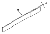
梁の接合部付近にALCパネルを取り付ける場合は専用の取り付け用金具を使用する必要がある。図3に梁の接合部に使用する取り付け用金具の一例を示す。また、この、取り付け用金具を使用して梁の接合部にALCパネルを取り付ける場合の接合構造を図4に示す。
従来は、図3に示すように鋼板製のフラットバーからなり、両端が梁上に固定される定規アングルの厚さ(d)分だけ略Z形に曲げられている取り付け用金具11が使用されていた。この取り付け用金具11を使用して梁の接合部にALCパネルを取り付けるには、図4に示すように、梁2の接合部13により分断された定規アングル16,16の端部間に、上記取り付け用金具11を溶接固定する。梁2,2の接合部13はスプライスプレート14がボルト15によって接合されている。そして取り付け用金具11に所定の自重受け金具7やパネル取り付け金具8を用いて図示省略のALCパネルを取り付けていた。取り付け用金具11は両端を同一方向に定規アングル16の厚さ(d)分だけ略Z形に折り曲げてあるので、取り付け用金具11と定規アングル16の建物外側面はほぼ同一平面となり、ALCパネルの自重受け金具7やパネル取り付け金具8を自由に取り付けることができるようになっている。
しかし、図3に示すような両端を略Z形に折り曲げたフラットバーからなる取り付け用金具は、ALCパネルの取り付け用金具としては、面外方向の外力に対し強度が不足しているので補強が必要である。ところが、スプライスプレートへの溶接は梁の構造上実施不可であるため、梁から控えを取るなどの補強ができない難点がある。
When mounting the ALC panel near the joint of the beam, it is necessary to use a dedicated mounting bracket. FIG. 3 shows an example of a mounting bracket used for the joint portion of the beam. Further, FIG. 4 shows a joining structure in the case where the ALC panel is attached to the joint portion of the beam using the mounting bracket.
Conventionally, as shown in FIG. 3, a
However, as shown in FIG. 3, the mounting bracket made of a flat bar having both ends bent into a substantially Z shape has insufficient strength against an external force in the out-of-plane direction as a mounting bracket for an ALC panel. is necessary. However, since welding to the splice plate is impossible due to the structure of the beam, there is a difficulty that reinforcement such as taking a refrain from the beam is not possible.
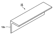
図5に梁の接合部に使用する取り付け用金具の別の例を示す。また、この取り付け用金具を使用して梁の接合部にALCパネルを取り付ける接合構造を図6に示す。
この取り付け用金具12はアングル鋼材からなり、図6に示すようにアングル鋼材の垂直面12aを定規アングル12の端部へ側面がコの字型を形成する様に沿わせ、それらの各端部同士を溶接固定して連結する。この取り付け用金具12に所定の自重受け金具7やパネル取り付け金具8を用いて図示省略のALCパネルを取り付けていた(例えば、特許文献1参照。)。
This
図5に示すようなアングルからなる取り付け用金具12の場合は、定規アングル16の端部との溶接固定をするに際して、それ単独ではすみ肉溶接ができない為に、フラットバーからなるピース片17を定規アングル16と取り付け用金具12の端部を跨ぐように沿わせ、確実に溶接固定出来るようにしなければならないが、これには施工手間がかかるという難点がある。
そこで、本発明の目的はALCパネルの取付容易性を維持したままで、その梁の接合部分における上記問題点を解決したパネルの取り付け用金具を提供することにある。
In the case of the
SUMMARY OF THE INVENTION Accordingly, an object of the present invention is to provide a panel mounting bracket that solves the above-mentioned problems in the joint portion of the beam while maintaining the ease of mounting of the ALC panel.
前記課題を解決する為に本発明のパネルの取り付け用金具は、水平部と垂直部とからなる鋼板で構成されており、該垂直部は両端が水平部よりも長く張り出しており、その張り出し部分は梁上に固定される定規アングルの厚さ分だけ略Z形に建築物の内側方向に曲げられているパネルの取り付け用金具とした。 In order to solve the above problems, the panel mounting bracket of the present invention is composed of a steel plate composed of a horizontal portion and a vertical portion, and the vertical portion has both ends protruding longer than the horizontal portion, and the protruding portion thereof Is a mounting bracket for a panel that is bent in an approximately Z-shape toward the inside of the building by the thickness of the ruler angle fixed on the beam.
以下に本発明の作用を説明する。
本発明のパネルの取り付け用金具は、断面が水平部と垂直部とからなる鋼板であって、垂直部は水平部よりも両端に張り出しており、その張り出し部分は水平部と同方向に、梁上に固定される定規アングルの厚さ分だけ略Z形に曲げられているため、定規アングルの端部への取り付けは、定規アングルの起立面に沿わせるのみで同一面を保って接合部で二分された定規アングルを連結することが可能であり、更には容易に確実な溶接固定が可能である。また、自重又は面外方向の外力に対しては、取り付け用金具の断面係数が非常に高くなるため、特別な補強をすることなく強度上の問題も解決できる。
The operation of the present invention will be described below.
The panel mounting bracket of the present invention is a steel plate having a cross section composed of a horizontal portion and a vertical portion, and the vertical portion protrudes at both ends from the horizontal portion, and the protruding portion is in the same direction as the horizontal portion. Since it is bent in the approximate Z shape by the thickness of the ruler angle that is fixed on the top, the ruler angle can be attached to the end of the ruler angle by keeping the same surface along the rising surface of the ruler angle. Divided ruler angles can be connected, and reliable welding can be easily performed. Moreover, since the section modulus of the mounting bracket is very high with respect to its own weight or an external force in the out-of-plane direction, the problem of strength can be solved without special reinforcement.
本発明のパネルの取り付け用金具を使用すれば、スプライスプレートにより二分された定規アングルを容易に連結することが可能であり、梁の接合部にALCパネルを取り付ける施工手間を削減することができる。また、ALCパネルは十分な取付強度をもって取り付けられ、層間変形追従性に優れた壁面を構成する事ができる。 By using the panel mounting bracket of the present invention, it is possible to easily connect the ruler angles divided by the splice plate, and it is possible to reduce the labor for mounting the ALC panel at the joint portion of the beam. In addition, the ALC panel is attached with sufficient attachment strength, and can constitute a wall surface excellent in inter-layer deformation followability.
以下、本発明の実施形態を図に基づいて説明する。
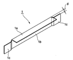
図1は本発明のパネルの取り付け用金具を示す斜視図である。図1に示すように本発明のパネルの取り付け用金具1は、水平部1aと垂直部1bとからなる鋼板から構成されており、垂直部1bは水平部1aよりも両端に張出した張出部1cを有していて、その張出部1cは水平部1aと同方向に、梁上に固定される定規アングルの厚さ(d)分だけ、建築物内側に向けて略Z形に曲げてある。
このようにパネルの取り付け用金具を構成すれば、建築物外側に対する強度も十分発揮され、取り付ける場合も定規アングルと同一平面を形成することが可能となり、しかも溶接固定も容易に実施することができる。
Hereinafter, embodiments of the present invention will be described with reference to the drawings.
FIG. 1 is a perspective view showing a mounting bracket for a panel according to the present invention. As shown in FIG. 1, the
If the mounting bracket for the panel is configured in this way, the strength against the outside of the building is also sufficiently exerted, and it becomes possible to form the same plane as the ruler angle even when mounting, and the welding and fixing can be easily performed. .
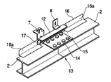
次に、上記パネルの取り付け用金具1を用いてALCパネルを構造体に取り付ける場合の取付構造を図2に示す。
梁2の接合部13の上面には、スプライスプレート14が複数のボルト15によって固定され、梁2,2を接合している。この梁の接合部分近傍では、定規アングル16がスプライスプレート14によって二分されている。二分された定規アングル16の端部同士は図1の取り付け用金具1によって溶接接合により連結されている。取り付け用金具1は、その両端の張出部1cを定規アングル16の起立面16aに沿わせ、張出部1cと直交する水平部1aを室内側に向けて溶接により連結されており、この取り付け用金具1の垂直面1bの中心付近に自重受け金具7やパネル取り付け金具8が溶接固定されている。
Next, FIG. 2 shows a mounting structure in the case where the ALC panel is mounted on the structure using the
A
さらに、図示省略の下階パネル頭部のパネル幅方向中心に取り付けられたパネルの自重受け機能を有する自重受け金具7が、パネルの取り付け用金具1の垂直部1bに溶接固定されて下階パネルを固定しており、そのパネルの取り付け用金具1の上に上階パネル足元のパネル幅方向中心が設置されると共に、その足元のパネル幅方向中心に取り付けられた断面L字形のパネル取り付け金具8が、取り付け用金具の水平部に設置され溶接固定される。
Further, a self-weight receiving bracket 7 having a self-weight receiving function for a panel attached to the center of the lower floor panel head (not shown) is welded and fixed to the
このような取り付け構造とすれば、取り付け金具が水平部と垂直部を有するアングル状の鋼板から構成されているので、建物外面方向の外力に対しても十分な強度を有し、スプライスプレートへの溶接も不要なので施工手間がかかることはない。 With such a mounting structure, the mounting bracket is composed of an angled steel plate having a horizontal part and a vertical part, so it has sufficient strength against external forces in the direction of the building outer surface, Since welding is not required, construction work is not required.
1:パネルの取り付け用金具、
2:梁、
3:接合部、
4:スプライスプレート、
5:ボルト、
6:定規アングル、
7:自重受け金具、
8:パネル取り付け金具、
11,12:取り付け用金具
1: Panel mounting bracket,
2: Beam,
3: Joint part,
4: Splice plate
5: Bolt,
6: Ruler angle,
7: Own weight bracket,
8: Panel mounting bracket,
11, 12: Mounting bracket
Claims (1)
A mounting bracket for an ALC wall panel to be attached to a splice plate portion fixed to a beam-to-beam junction, the mounting bracket being made of a steel plate composed of a horizontal portion and a vertical portion, the vertical portion being The ALC panel is characterized in that both ends project longer than the horizontal part, and the projecting part is bent in an approximately Z-shape toward the inside of the building by the thickness of the ruler angle fixed on the beam. Mounting bracket.
Priority Applications (1)
| Application Number | Priority Date | Filing Date | Title |
|---|---|---|---|
| JP2004068181A JP2005256366A (en) | 2004-03-10 | 2004-03-10 | Panel mounting bracket |
Applications Claiming Priority (1)
| Application Number | Priority Date | Filing Date | Title |
|---|---|---|---|
| JP2004068181A JP2005256366A (en) | 2004-03-10 | 2004-03-10 | Panel mounting bracket |
Publications (1)
| Publication Number | Publication Date |
|---|---|
| JP2005256366A true JP2005256366A (en) | 2005-09-22 |
Family
ID=35082369
Family Applications (1)
| Application Number | Title | Priority Date | Filing Date |
|---|---|---|---|
| JP2004068181A Pending JP2005256366A (en) | 2004-03-10 | 2004-03-10 | Panel mounting bracket |
Country Status (1)
| Country | Link |
|---|---|
| JP (1) | JP2005256366A (en) |
Cited By (2)
| Publication number | Priority date | Publication date | Assignee | Title |
|---|---|---|---|---|
| CN102513454A (en) * | 2012-01-12 | 2012-06-27 | 云南昆钢钢结构有限公司 | Z-shaped angle steel forming die |
| WO2012131952A1 (en) | 2011-03-30 | 2012-10-04 | トヨタ自動車株式会社 | Vehicle driving force control device |
-
2004
- 2004-03-10 JP JP2004068181A patent/JP2005256366A/en active Pending
Cited By (2)
| Publication number | Priority date | Publication date | Assignee | Title |
|---|---|---|---|---|
| WO2012131952A1 (en) | 2011-03-30 | 2012-10-04 | トヨタ自動車株式会社 | Vehicle driving force control device |
| CN102513454A (en) * | 2012-01-12 | 2012-06-27 | 云南昆钢钢结构有限公司 | Z-shaped angle steel forming die |
Similar Documents
| Publication | Publication Date | Title |
|---|---|---|
| TWI503468B (en) | The traverse of the outer wall to prevent accessories and the use of this part of the external wall construction structure | |
| JP6546781B2 (en) | Exterior material mounting structure | |
| JP2012107416A (en) | Beam joint structure | |
| JP2005256366A (en) | Panel mounting bracket | |
| JP2011052485A (en) | Reinforcing beam receiving metal fittings | |
| JP2006348490A (en) | Brace mounting structure | |
| JP4326926B2 (en) | Beam receiving hardware | |
| JP2010229662A (en) | Mounting structure and mounting method for extension unit and unit building | |
| JP5199856B2 (en) | External wall panel mounting structure | |
| JP2006089914A (en) | Joint device for horizontal member | |
| JP2005248701A (en) | Alc panel mounting structure | |
| JP2009249840A (en) | Flashing mounting structure of exterior wall with double-sided panel | |
| KR101413269B1 (en) | Light shape steel and assembly system using the same | |
| JPH0541157Y2 (en) | ||
| JP2007247220A (en) | Mounting structure of alc wall panel | |
| JP2007247380A (en) | Bay window and its construction method | |
| JP4891099B2 (en) | Member positioning structure for wall joints | |
| JP6906344B2 (en) | Furnace mounting bracket | |
| JPH10311113A (en) | Mounting structure for alc wall panel | |
| JP2023135415A (en) | Fitting member of wall panel, fitting structure, building and fitting method of wall panel | |
| JP4735496B2 (en) | Column and beam joint structure | |
| JP2009221689A (en) | Double sided panel exterior wall structure | |
| JP2005220533A (en) | Precast concrete slab | |
| JP2008144511A (en) | Lifting jig of panel | |
| JP4909161B2 (en) | 取 付 Mounting structure |