JP2005201441A - Rotary motion transmitter with casing which forms curved line pathway on flexible shaft - Google Patents
Rotary motion transmitter with casing which forms curved line pathway on flexible shaft Download PDFInfo
- Publication number
- JP2005201441A JP2005201441A JP2004366054A JP2004366054A JP2005201441A JP 2005201441 A JP2005201441 A JP 2005201441A JP 2004366054 A JP2004366054 A JP 2004366054A JP 2004366054 A JP2004366054 A JP 2004366054A JP 2005201441 A JP2005201441 A JP 2005201441A
- Authority
- JP
- Japan
- Prior art keywords
- casing
- transmission device
- shaft
- rotary motion
- hollow body
- Prior art date
- Legal status (The legal status is an assumption and is not a legal conclusion. Google has not performed a legal analysis and makes no representation as to the accuracy of the status listed.)
- Pending
Links
Images


Classifications
-
- F—MECHANICAL ENGINEERING; LIGHTING; HEATING; WEAPONS; BLASTING
- F16—ENGINEERING ELEMENTS AND UNITS; GENERAL MEASURES FOR PRODUCING AND MAINTAINING EFFECTIVE FUNCTIONING OF MACHINES OR INSTALLATIONS; THERMAL INSULATION IN GENERAL
- F16C—SHAFTS; FLEXIBLE SHAFTS; ELEMENTS OR CRANKSHAFT MECHANISMS; ROTARY BODIES OTHER THAN GEARING ELEMENTS; BEARINGS
- F16C1/00—Flexible shafts; Mechanical means for transmitting movement in a flexible sheathing
- F16C1/26—Construction of guiding-sheathings or guiding-tubes
- F16C1/267—Details of the inner surface of the sheathing or tube, e.g. coatings
-
- B—PERFORMING OPERATIONS; TRANSPORTING
- B60—VEHICLES IN GENERAL
- B60N—SEATS SPECIALLY ADAPTED FOR VEHICLES; VEHICLE PASSENGER ACCOMMODATION NOT OTHERWISE PROVIDED FOR
- B60N2/00—Seats specially adapted for vehicles; Arrangement or mounting of seats in vehicles
- B60N2/90—Details or parts not otherwise provided for
- B60N2/919—Positioning and locking mechanisms
- B60N2/933—Positioning and locking mechanisms rotatable
-
- F—MECHANICAL ENGINEERING; LIGHTING; HEATING; WEAPONS; BLASTING
- F16—ENGINEERING ELEMENTS AND UNITS; GENERAL MEASURES FOR PRODUCING AND MAINTAINING EFFECTIVE FUNCTIONING OF MACHINES OR INSTALLATIONS; THERMAL INSULATION IN GENERAL
- F16C—SHAFTS; FLEXIBLE SHAFTS; ELEMENTS OR CRANKSHAFT MECHANISMS; ROTARY BODIES OTHER THAN GEARING ELEMENTS; BEARINGS
- F16C1/00—Flexible shafts; Mechanical means for transmitting movement in a flexible sheathing
- F16C1/02—Flexible shafts; Mechanical means for transmitting movement in a flexible sheathing for conveying rotary movements
- F16C1/06—Flexible shafts; Mechanical means for transmitting movement in a flexible sheathing for conveying rotary movements with guiding sheathing, tube or box
-
- F—MECHANICAL ENGINEERING; LIGHTING; HEATING; WEAPONS; BLASTING
- F16—ENGINEERING ELEMENTS AND UNITS; GENERAL MEASURES FOR PRODUCING AND MAINTAINING EFFECTIVE FUNCTIONING OF MACHINES OR INSTALLATIONS; THERMAL INSULATION IN GENERAL
- F16C—SHAFTS; FLEXIBLE SHAFTS; ELEMENTS OR CRANKSHAFT MECHANISMS; ROTARY BODIES OTHER THAN GEARING ELEMENTS; BEARINGS
- F16C1/00—Flexible shafts; Mechanical means for transmitting movement in a flexible sheathing
- F16C1/10—Means for transmitting linear movement in a flexible sheathing, e.g. "Bowden-mechanisms"
- F16C1/108—Reducing or controlling of vibrations, e.g. by resilient damping of noise
-
- F—MECHANICAL ENGINEERING; LIGHTING; HEATING; WEAPONS; BLASTING
- F16—ENGINEERING ELEMENTS AND UNITS; GENERAL MEASURES FOR PRODUCING AND MAINTAINING EFFECTIVE FUNCTIONING OF MACHINES OR INSTALLATIONS; THERMAL INSULATION IN GENERAL
- F16C—SHAFTS; FLEXIBLE SHAFTS; ELEMENTS OR CRANKSHAFT MECHANISMS; ROTARY BODIES OTHER THAN GEARING ELEMENTS; BEARINGS
- F16C1/00—Flexible shafts; Mechanical means for transmitting movement in a flexible sheathing
- F16C1/24—Lubrication; Lubricating equipment
-
- F—MECHANICAL ENGINEERING; LIGHTING; HEATING; WEAPONS; BLASTING
- F16—ENGINEERING ELEMENTS AND UNITS; GENERAL MEASURES FOR PRODUCING AND MAINTAINING EFFECTIVE FUNCTIONING OF MACHINES OR INSTALLATIONS; THERMAL INSULATION IN GENERAL
- F16C—SHAFTS; FLEXIBLE SHAFTS; ELEMENTS OR CRANKSHAFT MECHANISMS; ROTARY BODIES OTHER THAN GEARING ELEMENTS; BEARINGS
- F16C2326/00—Articles relating to transporting
- F16C2326/01—Parts of vehicles in general
- F16C2326/08—Vehicle seats, e.g. in linear movable seats
-
- Y—GENERAL TAGGING OF NEW TECHNOLOGICAL DEVELOPMENTS; GENERAL TAGGING OF CROSS-SECTIONAL TECHNOLOGIES SPANNING OVER SEVERAL SECTIONS OF THE IPC; TECHNICAL SUBJECTS COVERED BY FORMER USPC CROSS-REFERENCE ART COLLECTIONS [XRACs] AND DIGESTS
- Y10—TECHNICAL SUBJECTS COVERED BY FORMER USPC
- Y10T—TECHNICAL SUBJECTS COVERED BY FORMER US CLASSIFICATION
- Y10T74/00—Machine element or mechanism
- Y10T74/20—Control lever and linkage systems
- Y10T74/20396—Hand operated
- Y10T74/20474—Rotatable rod, shaft, or post
Abstract
Description
本発明は、回転運動を伝達するための装置、及び同装置を備える自動車シート用の調整システムに関する。 The present invention relates to a device for transmitting rotational movement and to an adjustment system for an automobile seat comprising the device.
可撓性を備えたシャフト、及びシャフトを収容するケーシングを備える回転伝達装置は周知である。
このような伝達装置、特に、自動車のシートを調整するための装置においては、ケーシング内のシャフトの回転速度は、2000rpmより多く、従来はほぼ3000rpmである。
A rotation transmission device including a shaft having flexibility and a casing for housing the shaft is well known.
In such a transmission device, in particular a device for adjusting the seat of an automobile, the rotational speed of the shaft in the casing is greater than 2000 rpm and is conventionally approximately 3000 rpm.
そのような速度で回転できるようにするためには、シャフトとケーシングとの間に、10分の数ミリメートルの間隙が必要である。しかしながら、このような間隙は、回転中に振幅の小さい振動を起こし、その振動がシャフトに沿って伝わり、不快なノイズを発生させ、身体に不快感を与える。 In order to be able to rotate at such speeds, a gap of a few tenths of a millimeter is required between the shaft and the casing. However, such a gap causes a vibration having a small amplitude during rotation, and the vibration is transmitted along the shaft, generating an unpleasant noise and giving the body an unpleasant feeling.
振動に関するこの問題を解決するために、特許文献1は、そのケーシングが収縮した状態で少なくとも1つの変形を発生させる、即ち、ケーシングの直径が部分的に縮小するような回転伝達装置を提案している。この理由として、収縮がシャフトとケーシングとの間に強い接触を生じさせ、この接触により振動が制限されることが挙げられる。しかしながら、このような接触によりシャフトとケーシングとの間に大きな摩擦が生じ、本来の用途に必要な十分なシャフトの回転速度を得るためには、モータのトルクを増大させる必要が生ずる。更に、この摩擦はケーシングの変形部分の摩耗を早めることになる。
本発明の目的は、これらの問題を解決するために、ケーシングの内径を縮小することなく、振動を制限するように構成された永久的な変形を有するケーシングを備えた回転運動伝達装置を提供することにある。 In order to solve these problems, an object of the present invention is to provide a rotary motion transmission device including a casing having a permanent deformation configured to limit vibration without reducing the inner diameter of the casing. There is.
この目的を達成するため、及び第1の態様によれば、本発明は、可撓性を備えたシャフトと、同シャフトが収容されるケーシングとからなる回転運動を伝達するための装置に関する。ケーシングは、プラスチック材料からなる中空体から形成され、その内径は、ケーシングの内側でシャフトが回転できるように設定される。また、中空体の壁は異なる厚さを有するため、ケーシングの一部が長手方向に延びる波状の内面を有する。 In order to achieve this object and according to a first aspect, the present invention relates to a device for transmitting a rotational movement comprising a flexible shaft and a casing in which the shaft is accommodated. The casing is formed from a hollow body made of a plastic material, and its inner diameter is set so that the shaft can rotate inside the casing. Moreover, since the walls of the hollow body have different thicknesses, a part of the casing has a wavy inner surface extending in the longitudinal direction.
第2の態様において、本発明は、自動車の構造体に取り付けられた少なくとも1つの調整ランナーと、同ランナーにシートを固定するための調節可能な手段とを備える自動車のシートの調整システムに関する。同システムは、少なくとも1つの回転部分を備えた駆動モータを更に有し、また、駆動モータの出力部と固定手段との間に配置された上記の伝達装置を有して、出力部の回転に応じて調整ランナーに沿って固定手段を移動させる。 In a second aspect, the present invention relates to a vehicle seat adjustment system comprising at least one adjustment runner attached to a vehicle structure and adjustable means for securing the seat to the runner. The system further includes a drive motor having at least one rotating portion, and further includes the above-described transmission device disposed between the output portion of the drive motor and the fixing means to rotate the output portion. Accordingly, the fixing means is moved along the adjustment runner.
本発明の他の目的及び利点は、添付の図面を参照して以下の詳細な説明を読むことにより、明確に理解されるであろう。 Other objects and advantages of the present invention will be clearly understood by reading the following detailed description with reference to the accompanying drawings.
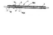
図1に示すように、回転運動伝達装置1は、可撓性を備えたシャフト2及びケーシング3を備える。シャフト2は、ケーシング3内に収容され、その内径はケーシング3内でシャフト2が回転できるように設定される。 As shown in FIG. 1, the rotational motion transmission device 1 includes a shaft 2 and a casing 3 having flexibility. The shaft 2 is accommodated in the casing 3, and the inner diameter thereof is set so that the shaft 2 can rotate in the casing 3.
本明細書において、「長手方向(longitudinal)」とは、図1及び2において示されるケーシング3の軸線Aに沿った方向である。
シャフト2の回転速度は、従来、約3000rpmである。 この速度で回転できるようにするためには、シャフト2とケーシング3との間に10分の数ミリメートルの間隙が必要である。
In the present specification, the “longitudinal direction” is a direction along the axis A of the casing 3 shown in FIGS.
The rotational speed of the shaft 2 is conventionally about 3000 rpm. In order to be able to rotate at this speed, a clearance of several tenths of a millimeter is required between the shaft 2 and the casing 3.
ケーシング3は、ポリウレタンなどのプラスチック材料から製造される。ケーシング3は、ピンの周囲にプラスチック材料を射出成形して製造されてもよい。
ケーシング3は、中空体から形成されており、内面4及び外面5を有する。内面とは、中空のシリンダーの壁を構成する面のことであり、ケーシング3の内側を構成する。
The casing 3 is manufactured from a plastic material such as polyurethane. The casing 3 may be manufactured by injection molding a plastic material around the pins.
The casing 3 is formed from a hollow body and has an
中空体の壁は異なる厚さを有するため、内面4はケーシング3の少なくとも一部を覆って長手方向に延びる波状部6を有する。そのため、図1に示すように、ケーシング3とシャフト2との間の接触点7において、ケーシング3の内側にわずかに曲がった経路を形成し、接触点7は、ケーシングの軸線Aに対して対向し、軸線Aのいずれかの側に交互に位置する。これらの接触点7は、シャフト2の回転を低下させないで、振動の発生を抑制する。モータのトルクは、変形部分を備えていないケーシングに使用されるモータのトルクと類似しているため、ケーシング3の変形部分が早く摩耗することはない。また、ケーシング3とシャフト2との間に形成された間隙に、シャフト2を円滑に回動させるためのグリースを保存する部分8を形成してもよい。
Since the walls of the hollow body have different thicknesses, the
図3に示される一実施例において、波状部6は、ケーシング3の内側に向かって延び、少なくともケーシング3の一部に沿って配置される突条部19により形成される。同図において、突条部19により、わずかに曲がった経路がケーシングの内側に形成される。突条部19は、いずれの形状の断面を有してもよく、特に三角形、円形の一部、菱形の一部、又は四角形の一部から選択されてもよい。 In the embodiment shown in FIG. 3, the corrugated portion 6 is formed by a ridge portion 19 that extends toward the inside of the casing 3 and is disposed along at least a part of the casing 3. In the same figure, a slightly curved path is formed inside the casing by the protrusion 19. The protrusion 19 may have a cross section of any shape, and may be selected in particular from a triangle, a part of a circle, a part of a rhombus, or a part of a quadrangle.
適切な方法で波状に形成されたピンの周囲でケーシングの成形が行われ、ケーシングが成形される間に波状部6が形成される。
一実施例において、波状部6はケーシング3の端部に構成され、ケーシングの残りの部分は、変形されていないケーシングと同様にほぼ円筒状の内面を有する。
The casing is molded around a pin that is waved in an appropriate manner, and the waved portion 6 is formed while the casing is being molded.
In one embodiment, the undulating portion 6 is configured at the end of the casing 3 and the remaining portion of the casing has a generally cylindrical inner surface similar to an undeformed casing.
他の実施例によれば、特に5cm乃至10cmなどの短いケーシングにおいては、内面4全体に、ケーシングの全長に沿って延びる波状部6が構成される。
波状部6は、連続状に形成される。しかし、これは絶対的要件ではなく、非連続的な波状部を形成してもよい。
According to another embodiment, particularly in short casings such as 5 cm to 10 cm, the entire
The wavy portion 6 is formed in a continuous shape. However, this is not an absolute requirement and may form a discontinuous wave.
図1及び図2に示される実施例において、ケーシングの外面5はほぼ円筒状である。従って、ケーシングは滑らかな外面を有する。同実施例は、特に、図1に示すように、ケーシング3が、伝達装置1のケーシングとしてガイダンスチューブ9の内側を進む場合に適している。
In the embodiment shown in FIGS. 1 and 2, the
この理由として、特定の用途において、ケーシング3が、その外径とほぼ等しい内径を有するガイダンスチューブ9の内側を進むことが挙げられる。ケーシングの外面5も変形されている場合は、チューブ9は、同チューブを変形させようとする力に対して、逆方向への力でチューブ押しつぶすようにしてチューブ本来の形状を維持し、さらにはケーシング3の内部で曲線状経路の形成を抑制するために、ほぼ円筒状の外面5が構成される。
This is because, in certain applications, the casing 3 travels inside a guidance tube 9 having an inner diameter approximately equal to its outer diameter. When the
一実施例において、ケーシング3の一端或いは両端は、チューブ9内に収容される。ケーシングは、図2に示すように、制限止め部10を形成する少なくとも1つの領域を有する。この領域10は、外面5から突出して延びる。ケーシング3の端部がチューブ内に挿入されると、チューブ9の端部は、止め部10を形成する領域に接触するため、チューブ内に進められるケーシングの長さが制限される。
In one embodiment, one or both ends of the casing 3 are accommodated in the tube 9. As shown in FIG. 2, the casing has at least one region that forms the
波状部6は、ケーシング3の内側に構成され、外面5は、ケーシング3を固定手段により支持部に固定できるように構成される。従って、ケーシング3の外面5は、異なる厚さを有するため、図3に示すように、支持部にケーシング3を固定する外部手段と共に領域20を形成する。固定手段とは、クリップやコネクタなどである。
The wavy portion 6 is configured inside the casing 3, and the
可撓性を備えたシャフトは、その周囲が切削加工されて滑らかになっていてもよい。そのため、ケーシング3内のシャフト2の摩擦が減少されるため回転が生じる。可撓性を備えたシャフト2は、例えば、フランス国特許出願公開第0303034号明細書に記載された実施例に合わせてもよい。 The shaft having flexibility may be smoothened by cutting the periphery thereof. For this reason, the friction of the shaft 2 in the casing 3 is reduced, so that rotation occurs. The shaft 2 with flexibility may be adapted to the embodiment described in, for example, French Patent Application No. 0303034.
一実施例において、シャフト2は、基部と端部の自由端との間に延びる最大の長さを超えてハウジング内に収容される少なくとも1つの端部を有し、同端部は、ベース部と自由端との間に延びる頂部が平面に切断された螺旋形のピラミッド状をなす。シャフトは、例えば、フランス国特許出願公開第0351001号明細書に記載された実施例に合わせてもよい。 In one embodiment, the shaft 2 has at least one end that is received within the housing beyond a maximum length extending between the base and the free end of the end, the end being a base portion. And a free end, a top portion extending in a spiral pyramid shape cut into a plane. The shaft may be adapted, for example, to the embodiment described in French Patent Application No. 0351001.
従って、シャフト2の端部は、その自由端まで減少する断面を有する。そのため、シャフトの断面がハウジングの内壁に接触するまでシャフトの端部をハウジング内に挿入することにより、ハウジングと正確で間隙のない連結が構成できる。 Thus, the end of the shaft 2 has a cross section that decreases to its free end. Therefore, by inserting the end portion of the shaft into the housing until the cross section of the shaft contacts the inner wall of the housing, an accurate and gapless connection can be configured.
端部が螺旋状の場合、シャフト2は、頂部が平面に切断されたピラミッドの縁部がハウジングの壁に干渉することにより回転すると、ハウジング内に固定される。更に、そのような異なる断面により、シャフト2は異なるハウジングの寸法に適合できる。 When the end is helical, the shaft 2 is fixed in the housing when the edge of the pyramid with the top cut into a plane is rotated by interfering with the wall of the housing. Furthermore, with such different cross sections, the shaft 2 can be adapted to different housing dimensions.
図4において、上記した回転運動伝達装置1を有する自動車シート11の調整システムについて説明する。
調整システム11は、自動車の構造体にある好適な手段(図示せず)により固定された2つのランナー12,13を有する。これらのランナーは、調整ノッチを有し、その機能については以下に述べる。
In FIG. 4, the adjustment system of the
The
ランナー12,13は、自動車シートのフレーム(図示せず)を支持し、同フレームのランナーに対する移動及び固定は、前記ノッチと協働する歯車をそれぞれ備えた縮小ギア14,15などの調節手段によって行われる。
The
電気モータ16は、自動車の構造体、又は異なる態様において、シートのフレームに固定される。このモータ16は、2つの回転出力部17,18を有する。これらの出力部17,18は、本発明の回転運動伝達装置1により、縮小ギア14,15にそれぞれ連結される。
The
伝達装置1は、可撓性を備えたシャフト2の端部を収容するハウジングにより、モータの出力部及び縮小ギアと連結する。端部とハウジングとは、端部の断面がハウジングの内壁と接触するまで端部を押すことにより、連結される。従って、可撓性を備えたシャフト2とハウジングとの間には間隙が生じないため、回転運動を効率よく伝達でき、システム11により発生するノイズを削減できる。
The transmission device 1 is connected to the output portion of the motor and the reduction gear by a housing that houses the end portion of the shaft 2 having flexibility. The end and the housing are connected by pushing the end until the cross section of the end contacts the inner wall of the housing. Accordingly, since no gap is generated between the shaft 2 having flexibility and the housing, the rotational motion can be transmitted efficiently, and noise generated by the
Claims (13)
Applications Claiming Priority (1)
| Application Number | Priority Date | Filing Date | Title |
|---|---|---|---|
| FR0351098A FR2864183B1 (en) | 2003-12-17 | 2003-12-17 | DEVICE FOR TRANSMITTING A ROTATION MOTION COMPRISING A SINUY PATH SHEATH FOR A FLEXIBLE TREE |
Related Child Applications (1)
| Application Number | Title | Priority Date | Filing Date |
|---|---|---|---|
| JP2011128414A Division JP5426609B2 (en) | 2003-12-17 | 2011-06-08 | Rotational motion transmission device having a casing that forms a curved path in a flexible shaft |
Publications (2)
| Publication Number | Publication Date |
|---|---|
| JP2005201441A true JP2005201441A (en) | 2005-07-28 |
| JP2005201441A5 JP2005201441A5 (en) | 2011-07-21 |
Family
ID=34508792
Family Applications (2)
| Application Number | Title | Priority Date | Filing Date |
|---|---|---|---|
| JP2004366054A Pending JP2005201441A (en) | 2003-12-17 | 2004-12-17 | Rotary motion transmitter with casing which forms curved line pathway on flexible shaft |
| JP2011128414A Expired - Fee Related JP5426609B2 (en) | 2003-12-17 | 2011-06-08 | Rotational motion transmission device having a casing that forms a curved path in a flexible shaft |
Family Applications After (1)
| Application Number | Title | Priority Date | Filing Date |
|---|---|---|---|
| JP2011128414A Expired - Fee Related JP5426609B2 (en) | 2003-12-17 | 2011-06-08 | Rotational motion transmission device having a casing that forms a curved path in a flexible shaft |
Country Status (4)
| Country | Link |
|---|---|
| US (1) | US7681473B2 (en) |
| EP (1) | EP1544484B1 (en) |
| JP (2) | JP2005201441A (en) |
| FR (1) | FR2864183B1 (en) |
Cited By (2)
| Publication number | Priority date | Publication date | Assignee | Title |
|---|---|---|---|---|
| WO2011086821A1 (en) * | 2010-01-14 | 2011-07-21 | シロキ工業株式会社 | Drive wire |
| JP2014520721A (en) * | 2011-07-21 | 2014-08-25 | ジョンソン コントロールズ メタルズ アンド メカニズムス ゲーエムベーハー アンド カンパニー カーゲー | Holding device for adjustment drive device of automobile seat |
Families Citing this family (5)
| Publication number | Priority date | Publication date | Assignee | Title |
|---|---|---|---|---|
| FR2888901B1 (en) * | 2005-07-22 | 2007-09-28 | Inderflex Technoflex Sa | DEVICE FOR TRANSMITTING ROTATIONAL MOVEMENT COMPRISING ZONES FORMING BEARING AND INTERNAL TUBE |
| EP2314330A1 (en) | 2009-10-23 | 2011-04-27 | ECP Entwicklungsgesellschaft mbH | Flexible shaft arrangement |
| FR2973303B1 (en) * | 2011-03-30 | 2014-10-10 | Inderflex Technoflex | SHEATH FOR FLEXIBLE ROTARY SHAFT, DEVICE FOR TRANSMITTING ROTATION MOVEMENT COMPRISING SUCH A SHEATH, DEVICE FOR ADJUSTING A SEAT HAVING SUCH A DEVICE FOR TRANSMITTING MOVEMENT. |
| GB2515304A (en) * | 2013-06-18 | 2014-12-24 | Antonio Fernando Pileci | A polymeric tubular control cable liner manufactured by extrusion and incorporating transverse internal lubricant retention cavities |
| US20200023720A1 (en) * | 2018-07-17 | 2020-01-23 | Brose Fahrzeugteile Gmbh & Co. Kg | Vehicle actuator cable dampener |
Citations (5)
| Publication number | Priority date | Publication date | Assignee | Title |
|---|---|---|---|---|
| JPS6162614A (en) * | 1984-09-04 | 1986-03-31 | Nippon Denso Co Ltd | Drive cable of meter for vehicle |
| JPS62188610U (en) * | 1986-05-21 | 1987-12-01 | ||
| JPS6417845A (en) * | 1987-07-13 | 1989-01-20 | Nishida Kogyo Kk | Production of products in which rust surface is utilized for decoration |
| JPH06330930A (en) * | 1993-05-20 | 1994-11-29 | Aisin Seiki Co Ltd | Power transmission device |
| JPH08267574A (en) * | 1995-03-31 | 1996-10-15 | Tokai Rubber Ind Ltd | Outer casing of control cable and method and apparatus for producing the same |
Family Cites Families (13)
| Publication number | Priority date | Publication date | Assignee | Title |
|---|---|---|---|---|
| DE1575715B1 (en) * | 1967-02-02 | 1969-10-23 | Golde Gmbh H T | Process for the production of a protective tube from a profile wire helix for a shaft guided with radial play |
| US3581523A (en) * | 1969-02-24 | 1971-06-01 | Merit Plastics Inc | Flexible cable assembly |
| GB1380762A (en) * | 1971-11-25 | 1975-01-15 | Kirchner F | Protective sheath for flexible shafts |
| US3812738A (en) * | 1972-04-06 | 1974-05-28 | Weatherhead Co | Flexible cable assembly |
| JPS5362627A (en) * | 1976-11-16 | 1978-06-05 | Yamada Kikai Kogyo Kk | Power working machine |
| US4915340A (en) * | 1987-07-24 | 1990-04-10 | Asin Seiki Kabushiki Kaisha | Power seat apparatus having a low friction transmission cable |
| DE4035231C2 (en) * | 1990-11-06 | 1995-07-06 | Wolf Woco & Co Franz J | Device for train insulation |
| US5931736A (en) * | 1997-06-20 | 1999-08-03 | B.W. Elliot Manufacturing Co., Inc. | Liner for rotating drive cables |
| US6038819A (en) * | 1997-08-05 | 2000-03-21 | Asc Incorporated | Powered drive assembly |
| DE10040594A1 (en) * | 2000-08-16 | 2002-03-07 | Keiper Gmbh & Co | Longitudinal adjustment device for motor vehicles |
| DE20014561U1 (en) * | 2000-08-23 | 2000-11-23 | Unicor Rohrsysteme Gmbh | Flexible drive shaft |
| DE20216127U1 (en) * | 2001-10-18 | 2003-02-27 | Uponor Innovation Ab | Sleeve for transmission shaft has narrow sections between wider sections and with a grooved or corrugated structure to reduce vibrations |
| US7080869B2 (en) * | 2002-11-18 | 2006-07-25 | Inderflex-Technoflex | Rotation transmission device comprising bearing-forming zones |
-
2003
- 2003-12-17 FR FR0351098A patent/FR2864183B1/en not_active Expired - Lifetime
-
2004
- 2004-12-14 US US11/011,625 patent/US7681473B2/en not_active Expired - Fee Related
- 2004-12-14 EP EP04292990.1A patent/EP1544484B1/en active Active
- 2004-12-17 JP JP2004366054A patent/JP2005201441A/en active Pending
-
2011
- 2011-06-08 JP JP2011128414A patent/JP5426609B2/en not_active Expired - Fee Related
Patent Citations (5)
| Publication number | Priority date | Publication date | Assignee | Title |
|---|---|---|---|---|
| JPS6162614A (en) * | 1984-09-04 | 1986-03-31 | Nippon Denso Co Ltd | Drive cable of meter for vehicle |
| JPS62188610U (en) * | 1986-05-21 | 1987-12-01 | ||
| JPS6417845A (en) * | 1987-07-13 | 1989-01-20 | Nishida Kogyo Kk | Production of products in which rust surface is utilized for decoration |
| JPH06330930A (en) * | 1993-05-20 | 1994-11-29 | Aisin Seiki Co Ltd | Power transmission device |
| JPH08267574A (en) * | 1995-03-31 | 1996-10-15 | Tokai Rubber Ind Ltd | Outer casing of control cable and method and apparatus for producing the same |
Cited By (3)
| Publication number | Priority date | Publication date | Assignee | Title |
|---|---|---|---|---|
| WO2011086821A1 (en) * | 2010-01-14 | 2011-07-21 | シロキ工業株式会社 | Drive wire |
| JP2011144862A (en) * | 2010-01-14 | 2011-07-28 | Shiroki Corp | Fitting structure |
| JP2014520721A (en) * | 2011-07-21 | 2014-08-25 | ジョンソン コントロールズ メタルズ アンド メカニズムス ゲーエムベーハー アンド カンパニー カーゲー | Holding device for adjustment drive device of automobile seat |
Also Published As
| Publication number | Publication date |
|---|---|
| EP1544484A2 (en) | 2005-06-22 |
| EP1544484B1 (en) | 2013-05-01 |
| EP1544484A3 (en) | 2006-11-08 |
| US7681473B2 (en) | 2010-03-23 |
| US20050173960A1 (en) | 2005-08-11 |
| FR2864183A1 (en) | 2005-06-24 |
| JP2011169470A (en) | 2011-09-01 |
| JP5426609B2 (en) | 2014-02-26 |
| FR2864183B1 (en) | 2007-04-06 |
Similar Documents
| Publication | Publication Date | Title |
|---|---|---|
| JP5426609B2 (en) | Rotational motion transmission device having a casing that forms a curved path in a flexible shaft | |
| CN107559382B (en) | Vehicle retarder | |
| US6390264B2 (en) | Clutch and motor including such clutch | |
| JP2010095006A (en) | Electric power steering device | |
| JP2008002526A (en) | Worm and motor device | |
| JP2009047267A (en) | Worm and motor device | |
| JP4277245B2 (en) | Actuator | |
| JP6077096B2 (en) | Grease leakage prevention structure for gear reducer | |
| JP7431564B2 (en) | Separation structure between internal gear and housing, planetary gear device, and actuator | |
| US6450056B2 (en) | Motor having speed reduction device | |
| JP2008039085A (en) | Rotary damper device | |
| EP1122390A2 (en) | Clutch and motor including such clutch | |
| JP2005201441A5 (en) | ||
| KR102018496B1 (en) | Sliding gear box for vehicle | |
| JP2005054950A (en) | Motor actuator and gear reducer mechanism | |
| JP5369661B2 (en) | Electric toilet seat device | |
| JP6288833B2 (en) | Steering device | |
| US7080869B2 (en) | Rotation transmission device comprising bearing-forming zones | |
| JP2005110449A (en) | Electric motor with speed reduction mechanism | |
| JP4239810B2 (en) | Steering gear device | |
| JPH0753406Y2 (en) | Motor shaft support | |
| KR200192395Y1 (en) | One way clutch | |
| JP2000081031A (en) | Bearing device and manufacture of the bearing device | |
| JP6945799B2 (en) | Rear wheel steering device | |
| JP2004084922A (en) | Rotation transmitting cable and fitting looseness preventive structure of this rotation transmitting cable and rotor |
Legal Events
| Date | Code | Title | Description |
|---|---|---|---|
| A521 | Written amendment |
Free format text: JAPANESE INTERMEDIATE CODE: A523 Effective date: 20071210 |
|
| A621 | Written request for application examination |
Free format text: JAPANESE INTERMEDIATE CODE: A621 Effective date: 20071210 |
|
| A131 | Notification of reasons for refusal |
Free format text: JAPANESE INTERMEDIATE CODE: A131 Effective date: 20100601 |
|
| A601 | Written request for extension of time |
Free format text: JAPANESE INTERMEDIATE CODE: A601 Effective date: 20100901 |
|
| A602 | Written permission of extension of time |
Free format text: JAPANESE INTERMEDIATE CODE: A602 Effective date: 20100906 |
|
| A601 | Written request for extension of time |
Free format text: JAPANESE INTERMEDIATE CODE: A601 Effective date: 20100929 |
|
| A602 | Written permission of extension of time |
Free format text: JAPANESE INTERMEDIATE CODE: A602 Effective date: 20101004 |
|
| A524 | Written submission of copy of amendment under section 19 (pct) |
Free format text: JAPANESE INTERMEDIATE CODE: A524 Effective date: 20101028 |
|
| A02 | Decision of refusal |
Free format text: JAPANESE INTERMEDIATE CODE: A02 Effective date: 20110208 |
|
| A524 | Written submission of copy of amendment under section 19 (pct) |
Free format text: JAPANESE INTERMEDIATE CODE: A524 Effective date: 20110608 |
|
| A911 | Transfer of reconsideration by examiner before appeal (zenchi) |
Free format text: JAPANESE INTERMEDIATE CODE: A911 Effective date: 20110713 |
|
| A912 | Removal of reconsideration by examiner before appeal (zenchi) |
Free format text: JAPANESE INTERMEDIATE CODE: A912 Effective date: 20110812 |
|
| A601 | Written request for extension of time |
Free format text: JAPANESE INTERMEDIATE CODE: A601 Effective date: 20111124 |
|
| A602 | Written permission of extension of time |
Free format text: JAPANESE INTERMEDIATE CODE: A602 Effective date: 20111129 |
|
| RD04 | Notification of resignation of power of attorney |
Free format text: JAPANESE INTERMEDIATE CODE: A7424 Effective date: 20120120 |