JP2005198743A - Three-dimensional view point measuring device - Google Patents
Three-dimensional view point measuring device Download PDFInfo
- Publication number
- JP2005198743A JP2005198743A JP2004006359A JP2004006359A JP2005198743A JP 2005198743 A JP2005198743 A JP 2005198743A JP 2004006359 A JP2004006359 A JP 2004006359A JP 2004006359 A JP2004006359 A JP 2004006359A JP 2005198743 A JP2005198743 A JP 2005198743A
- Authority
- JP
- Japan
- Prior art keywords
- camera
- pupil
- light source
- sight
- image
- Prior art date
- Legal status (The legal status is an assumption and is not a legal conclusion. Google has not performed a legal analysis and makes no representation as to the accuracy of the status listed.)
- Granted
Links
- 210000001747 pupil Anatomy 0.000 claims abstract description 66
- 239000013598 vector Substances 0.000 claims description 36
- 230000001360 synchronised effect Effects 0.000 claims description 4
- 238000005259 measurement Methods 0.000 claims 1
- 210000001508 eye Anatomy 0.000 abstract description 45
- 210000004087 cornea Anatomy 0.000 abstract description 10
- 238000000034 method Methods 0.000 description 16
- 210000003128 head Anatomy 0.000 description 11
- 238000001514 detection method Methods 0.000 description 10
- 210000005252 bulbus oculi Anatomy 0.000 description 9
- 238000010586 diagram Methods 0.000 description 7
- 230000003287 optical effect Effects 0.000 description 6
- 230000000007 visual effect Effects 0.000 description 4
- 230000008901 benefit Effects 0.000 description 3
- 238000005286 illumination Methods 0.000 description 3
- 238000012935 Averaging Methods 0.000 description 2
- 0 CCC(C)(C)*(C1ICCC1)S Chemical compound CCC(C)(C)*(C1ICCC1)S 0.000 description 2
- 210000001742 aqueous humor Anatomy 0.000 description 2
- 238000012937 correction Methods 0.000 description 2
- 238000010191 image analysis Methods 0.000 description 2
- 239000004973 liquid crystal related substance Substances 0.000 description 2
- 238000012545 processing Methods 0.000 description 2
- 238000012360 testing method Methods 0.000 description 2
- XCIXKGXIYUWCLL-UHFFFAOYSA-N OC1CCCC1 Chemical compound OC1CCCC1 XCIXKGXIYUWCLL-UHFFFAOYSA-N 0.000 description 1
- 241001469893 Oxyzygonectes dovii Species 0.000 description 1
- 206010033799 Paralysis Diseases 0.000 description 1
- 238000004458 analytical method Methods 0.000 description 1
- 230000000694 effects Effects 0.000 description 1
- 230000005611 electricity Effects 0.000 description 1
- 210000000720 eyelash Anatomy 0.000 description 1
- 230000001815 facial effect Effects 0.000 description 1
- 230000003760 hair shine Effects 0.000 description 1
- 238000004519 manufacturing process Methods 0.000 description 1
- 230000011514 reflex Effects 0.000 description 1
- 210000001525 retina Anatomy 0.000 description 1
- 230000035945 sensitivity Effects 0.000 description 1
- 238000012546 transfer Methods 0.000 description 1
- 230000004382 visual function Effects 0.000 description 1
Images


Abstract
Description
この発明は、人の両目の視線方向を同時に検出することにより、三次元視点を計測する装置に関する。 The present invention relates to an apparatus for measuring a three-dimensional viewpoint by simultaneously detecting the gaze direction of both eyes of a person.
・特許文献1(特許2739331号:ATR)には、網膜の反射を使用することによって瞳孔検出し、顔画像から瞳孔中心30の3次元位置を2台のカメラで捉えて三角測量によって決める技術が記載されている。これは瞳孔の3次元位置を検出しているものと考えられる。また、照明光として別の波長のものを用意する必要がある。
・特許文献2(特開平10−066678号公報:NTT,NAC)には、顔面に3点のマーカを貼付し、ステレオタイプの2台のワイドカメラにより眼球位置を検出し、1台のナローカメラにより眼球トラッキングを行なう技術が記載されている。
・特許文献3(特許第2988235号:日産自動車)には、複数の照明により角膜反射像から角膜球中心を求め、角膜球中心と瞳孔中心とから視線方向を求める技術が記載されている。
・特許文献4(特許第3324295号:日産自動車)には、特許文献3と同様に複数の照明により角膜反射像から角膜球中心を求め、角膜球中心と瞳孔中心とから視線方向を求める技術が記載されている。これらの技術はいずれも視線方向の向いている視点の位置を求めるものではなく、あくまでも視線方向を検出する技術である。
In Patent Document 2 (Japanese Patent Laid-Open No. 10-066668: NTT, NAC), three markers are attached to the face, the eyeball position is detected by two stereo-type wide cameras, and one narrow camera Describes a technique for performing eye tracking.
Patent Document 3 (Patent No. 2988235: Nissan Motor Co., Ltd.) describes a technique for obtaining a corneal sphere center from a corneal reflection image by a plurality of illuminations and obtaining a line-of-sight direction from the corneal sphere center and the pupil center.
Patent Document 4 (Japanese Patent No. 3324295: Nissan Motor Co., Ltd.) has a technique for obtaining a corneal sphere center from a corneal reflection image by a plurality of illuminations and obtaining a line-of-sight direction from the corneal sphere center and pupil center as in
この発明は、従来の視線方向の検出に留まらず視線の収束点を求めることにより、視点の3次元位置を求めるものである。
本装置は、被験者の顔から離れた2台のカメラの開口近傍に設けた光源で顔全体を照らし、それら2台のカメラで捉えた両目を含む顔画像から、頭部の前後、左右の大きな動き(たとえば、30cm)を許容しながら非接触で両目の視線を同時に検出できる非接触視線検出装置であって2台のカメラで捉えた顔画像から三角測量により、2つの瞳孔の3次元位置を検出し、さらに2つの顔画像のそれぞれにおいて検出される2つの瞳孔のそれぞれの周りを詳細に解析し、2つの正確な瞳孔中心と2つの角膜反射中心を検出し、2つの眼の視線を検出する。それら2本の視線の交点が視点であり、三次元の視点の計測ができる。
In the present invention, the three-dimensional position of the viewpoint is obtained by obtaining the convergence point of the line of sight without being limited to the conventional detection of the line of sight.
This device illuminates the entire face with a light source provided in the vicinity of the openings of two cameras away from the subject's face, and from the face image including both eyes captured by these two cameras, A non-contact gaze detection device that can detect the gaze of both eyes simultaneously in a non-contact manner while allowing movement (for example, 30 cm), and the three-dimensional positions of the two pupils are determined by triangulation from face images captured by two cameras. In addition, the two pupil images detected in each of the two facial images are analyzed in detail, and two accurate pupil centers and two corneal reflection centers are detected, and two eyes are detected. To do. The intersection of these two lines of sight is the viewpoint, and a three-dimensional viewpoint can be measured.
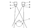
図1のように、2台のカメラ1、2を被験者の顔7から離れたところに設置し、それら2台のカメラのレンズ3,4の実質的に開口の中、もしくは、開口の近くに同一の波長の光源5、6を設け、顔7の全体を照らす。2つのカメラ1、2を同期させて駆動させ、2つのカメラに取り付けられている光源5、6を奇数フィールドと偶数フィールドに同期させて交互に点灯させる。
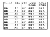
図2に示すように、カメラ1に取り付けてある光源5を奇数フィールドで点灯させると、カメラ1の奇数フィールドの画像では瞳孔が周囲より明るく写る現象が起こり(明瞳孔:図3左)、カメラ2の奇数フィールドの画像には瞳孔が周囲よりも暗く写る現象が起こる(暗瞳孔:図3右)。
同様に、カメラ2に取り付けてある光源6を偶数フィールドで点灯させると、カメラ1とカメラ2の偶数フィールドの画像において、それぞれの暗瞳孔(図4左)と明瞳孔(図4右)が観察される。
As shown in FIG. 1, two
As shown in FIG. 2, when the
Similarly, when the
基本的に各カメラから得られる連続する明瞳孔画像から暗瞳孔画像を画像差分することにより、瞳孔以外の部分が相殺しあって、瞳孔部のみが容易に検出できる。
瞳孔検出処理の高速化のためには、初期画像においては、画面全体に対して、飛び飛びの画素を解析することにより、2つの瞳孔のおよそのありかを検出する。その後、検出したおよその瞳孔を中心にウインドウを与え(図5中の2つの四角)、次のフレームからは、同ウインドウ内だけを画像解析をするか、もしくは、はじめからカメラからウインドウ内の画像だけを取り込み、画像解析にかかる時間を短縮する。
2つのウインドウ内の解析においては、基本的に全画素を詳細に解析し、両目の瞳孔中心と角膜反射中心を精度よく検出し、視線を決定する(図6)。
Basically, by subtracting the dark pupil image from the continuous bright pupil image obtained from each camera, portions other than the pupil cancel each other, and only the pupil portion can be easily detected.
In order to increase the speed of the pupil detection process, in the initial image, the approximate presence of the two pupils is detected by analyzing the skipped pixels for the entire screen. Then, a window is given around the detected approximate pupil (two squares in FIG. 5), and from the next frame, image analysis is performed only within the same window, or an image in the window from the camera from the beginning. Only to capture the time required for image analysis.
In the analysis in the two windows, basically all pixels are analyzed in detail, the pupil center and the corneal reflection center of both eyes are detected accurately, and the line of sight is determined (FIG. 6).
イメージセンサとしては高細精度でかつランダムアクセスもしくはウインドウ切り出しのできるCMOSセンサなどを利用し、イメージセンサから画像処理部へのデータ転送を高速化する。それにより、瞳孔中心と角膜反射中心の座標の検出を頻繁に行えることにする。得られる視線もしくは視点データを移動平均することにより、よりこれらを安定させることができる。
さらに、差分をする連続する2つの画像間の時間間隔を短くすることによって、2つの画像における瞳孔像に位置ずれが生じにくいために、視点や視線だけでなく、三次元瞳孔位置の精度や検出率の向上に寄与する。それにより頭部が移動して瞳孔像がカメラフレーム内をすばやく移動しても、差分により瞳孔が検出しやすくすると同時に、2つのカメラの同期を実質的に取ることを可能にする。
なお、カメラ2台を使用することは変わらないが、光源を増やしたり光学フィルターを利用したり、専用のカメラを製作することで、カメラ同士の同期のずれを改善する方法などが考えられる。
As the image sensor, a high-precision CMOS sensor capable of random access or window cutout is used to speed up data transfer from the image sensor to the image processing unit. As a result, the coordinates of the pupil center and the corneal reflection center can be frequently detected. By moving and averaging the obtained line of sight or viewpoint data, these can be further stabilized.
Furthermore, since the time interval between two consecutive images that make a difference is shortened, it is difficult for positional deviations to occur in the pupil images in the two images, so that not only the viewpoint and line of sight but also the accuracy and detection of the three-dimensional pupil position are detected. It contributes to the improvement of the rate. Thereby, even if the head moves and the pupil image quickly moves in the camera frame, the pupil is easily detected by the difference, and at the same time, the two cameras can be substantially synchronized.
Although the use of two cameras does not change, there may be a method of improving the synchronization gap between the cameras by increasing the number of light sources, using an optical filter, or manufacturing a dedicated camera.
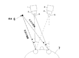
基本的に2つのカメラのそれぞれにおいて両方の目の視線を検出することができる。いま、図7に示すように、片目の視線は、まず、2台のカメラのカメラ較正を行った際に構成される世界座標系における瞳孔の三次元座標を2台のカメラから得られる瞳孔座標から推定する。いま、向かって左側のカメラのみに注目すると、カメラ較正により 求まるこのカメラの座標と推定された瞳孔三次元座標より、世界座標系におけるカメラ−瞳孔ベクトルが求まる。視線ベクトルを瞳孔から視点へ向かうベクトルとすると、カメラ−瞳孔ベクトルと視線ベクトルのなす角度は図中のθとφで表現できる。ここで、θは±30度程度の範囲で、図8に示す画像中の角膜反射中心から瞳孔中心へ向かうベクトルrの長さ|r|とほぼ線形関係がある(θ=k|r|、ただし、kは定数)。また、φはrの方向を示すφ’とφ=φ’の関係がある。視点Gは、視線ベクトルと視対象との交点として求まる。
視対象の存在する平面が不明であるときには、両目の視線ベクトルの交点が視点Gである。
Basically, the line of sight of both eyes can be detected in each of the two cameras. Now, as shown in FIG. 7, the line of sight of one eye is the pupil coordinates obtained from the two cameras using the three-dimensional coordinates of the pupil in the world coordinate system constructed when the cameras of the two cameras are calibrated. Estimated from Now, focusing only on the camera on the left side, the camera-pupil vector in the world coordinate system can be obtained from the camera coordinates obtained by camera calibration and the estimated pupil three-dimensional coordinates. If the line-of-sight vector is a vector from the pupil toward the viewpoint, the angle formed by the camera-pupil vector and the line-of-sight vector can be expressed by θ and φ in the figure. Here, θ is in the range of about ± 30 degrees, and has a substantially linear relationship with the length | r | of the vector r from the corneal reflection center to the pupil center in the image shown in FIG. 8 (θ = k | r |, Where k is a constant). Further, φ has a relationship of φ ′ indicating the direction of r and φ = φ ′. The viewpoint G is obtained as an intersection between the line-of-sight vector and the visual target.
When the plane on which the visual target exists is unknown, the intersection point of the line-of-sight vectors of both eyes is the viewpoint G.
これらの処理は、片目の視線ベクトルについても、2つのカメラのそれぞれから求まるので、それらの平均を最終的な視線ベクトルとすることもできる。また、θが大きくなると角膜反射が消失し、代わりに白目が光るようになり、事実上、瞳孔中心と角膜反射中心との相対位置関係から視線を検出することが不可能となったとき(例えば、図7において向かって右側のカメラのさらに右側を見たとき)、左側のカメラによって視線を検出するのは難しいので、右側のカメラから求まる視線ベクトルのみを利用するなどの工夫をする。
さらに大きく右を見たときは、右側のカメラでさえも角膜反射が検出できなくなる。その場合は、瞳孔の楕円度からおよその視線方向を検出する。θ>30°のとき、もしくは何らかの理由(例えば、眼鏡反射やまつげが角膜反射に重なったとき)で角膜反射が検出不可能なとき瞳孔の楕円度を利用することとする。このように、瞳孔の楕円度を利用する方法は精度の面で問題があるものの、正面に対して大きくずれたところを見た場合であって精度を必要としない場合などに有効である。
Since these processes are also obtained from each of the two cameras for the eye-gaze vector of one eye, the average of them can be used as the final eye-gaze vector. In addition, when θ increases, the corneal reflection disappears and instead the white eye shines, and when it becomes practically impossible to detect the line of sight from the relative positional relationship between the pupil center and the corneal reflection center (for example, 7 (when the right side of the right camera is further viewed in FIG. 7), it is difficult to detect the line of sight with the left camera, and therefore, a contrivance is made such as using only the line of sight vector obtained from the right camera.
When looking further to the right, even the right camera cannot detect corneal reflection. In that case, an approximate gaze direction is detected from the ellipticity of the pupil. The pupil ellipticity is used when θ> 30 ° or when corneal reflection cannot be detected for some reason (for example, when eyeglass reflection or eyelashes overlap with corneal reflection). As described above, although the method using the ellipticity of the pupil has a problem in terms of accuracy, it is effective in the case where the accuracy is not required, for example, when the position is largely deviated from the front.
ここで、角膜反射と瞳孔中心との相対座標から視線方向が検出できる理由を以下に述べる。
<角膜反射の特徴>
図11左のように、光源21(点光源)から発射した光が、反射平面で反射し、カメラに入射する場合、入射角と反射角が等しいため、このように表現される。ここで、対象は平面ではなく、球面だとすると図11右のように表現できる。この場合、カメラ20から見たとき、あたかも光源21は、球面の接平面25と球面24との接点22にあるように見える。このとき球面の中心23と接点22とを結ぶ直線に対し、入射角と反射角が等しくなる。
Here, the reason why the line-of-sight direction can be detected from the relative coordinates between the corneal reflection and the pupil center will be described below.
<Characteristics of corneal reflection>
As shown in the left of FIG. 11, when the light emitted from the light source 21 (point light source) is reflected by the reflection plane and enters the camera, the incident angle is equal to the reflection angle, which is expressed in this way. Here, if the target is not a plane but a spherical surface, it can be expressed as shown in the right of FIG. In this case, when viewed from the
ここで、もし、球面(眼球の角膜)が空間内をカメラ20と光源21に対して移動すると、図12左のように、カメラ20から見ると光源21の反射はカメラから視角が変化するため画像中で移動する。このように一般に球面を角膜球面と考えると、角膜が頭部の動きなどで移動すると角膜反射像が画像中で移動することがわかる。さらに、光源21の位置や、カメラ20の位置や方向が異なった場合も、角膜反射像の位置がカメラ画像内で異なってくることが容易に想像できる。
Here, if the spherical surface (eyeball cornea) moves in space with respect to the
今、光源とカメラの位置が一致している場合を考える(図12右)。この場合は、光源から球面へ向かう光線と球面からカメラへ戻る光線とは一致する。このような条件では、光源とカメラが異なる位置にある場合よりも優れている。なぜならば、光源とカメラの位置が不一致の場合は,図13左のように、光源とカメラに対して奥行き方向の動きをすると、角膜反射像が画像中で移動するが、一致している場合(図13右)には、カメラの撮影方向に対する固定した角度上を角膜球が移動する場合に画像中では同じ位置に撮影されるという特徴がある。したがって、光源とカメラの位置が一致している場合は、角膜反射像について問題になるのは、カメラ(光源)周りの回転だけである。 Consider a case where the light source and the camera are in the same position (right in FIG. 12). In this case, the light beam traveling from the light source to the spherical surface matches the light beam returning from the spherical surface to the camera. Under such conditions, the light source and the camera are superior to those at different positions. This is because, when the positions of the light source and the camera do not match, the corneal reflection image moves in the image when the light source and the camera move in the depth direction as shown in the left of FIG. (Right in FIG. 13) is characterized in that when the corneal sphere moves on a fixed angle with respect to the shooting direction of the camera, it is shot at the same position in the image. Therefore, when the positions of the light source and the camera coincide with each other, only the rotation around the camera (light source) is a problem with respect to the cornea reflection image.
<撮影画像中の角膜反射中心と瞳孔中心の間の距離|r|からカメラ-瞳孔ベクトルと視線ベクトルとのなす角度がわかる理由と方法>
図14のように、視線検出用カメラの視野内を眼球が移動するとする。いま、ステレオカメラによって、瞳孔の三次元位置がわかっているので、瞳孔がカメラおよび光源から同一の距離上を移動したとする。ただし、そのとき、カメラ-瞳孔ベクトルと視線ベクトルのなす角度θは変化しなかったとする。ただし、ここでは、簡単のため、カメラの水平軸上を瞳孔(眼球)が動いたとする。このとき、注意すべきことは、カメラから見た角膜反射像と瞳孔像の位置関係は全く変化しないことである。瞳孔がカメラ(レンズ,光源)を中心とした円周上を動くときは、画像上で角膜反射像と瞳孔像の相対距離は変化しない。
<Reason and method for determining the angle between the camera-pupil vector and the line-of-sight vector from the distance | r | between the corneal reflection center and the pupil center in the photographed image>
As shown in FIG. 14, it is assumed that the eyeball moves within the visual field of the line-of-sight detection camera. Now, since the three-dimensional position of the pupil is known by the stereo camera, it is assumed that the pupil has moved the same distance from the camera and the light source. However, at that time, it is assumed that the angle θ formed by the camera-pupil vector and the line-of-sight vector does not change. However, here, for simplicity, it is assumed that the pupil (eyeball) moves on the horizontal axis of the camera. At this time, it should be noted that the positional relationship between the cornea reflection image and the pupil image viewed from the camera does not change at all. When the pupil moves on the circumference around the camera (lens, light source), the relative distance between the corneal reflection image and the pupil image does not change on the image.
一方で、図15左のように、視線ベクトルの起点が同じ(瞳孔の3次元位置が同一)方向ベクトルが異なるときを考えると、このとき、図のように角膜反射の位置が変化する。カメラから見ると、カメラ−瞳孔ベクトルに対する視線ベクトルのなす角度が大きくなるほど、すなわちθが大きくなると画像中の角膜反射中心―瞳孔中心間の距離|r|は、大きくなることがわかる。また、図15右が示すように、目がカメラの方を向いているとき、基本的に瞳孔中心に角膜反射中心が位置し、|r|=0となる。 On the other hand, as shown in the left of FIG. 15, when the direction vectors of the same line-of-sight vector (the same three-dimensional position of the pupil) are different, the position of corneal reflection changes as shown in the figure. From the viewpoint of the camera, it can be seen that as the angle formed by the line-of-sight vector with respect to the camera-pupil vector increases, that is, when θ increases, the distance | r | between the corneal reflection center and the pupil center in the image increases. Further, as shown in the right of FIG. 15, when the eye is facing the camera, the corneal reflection center is basically located at the center of the pupil, and | r | = 0.
したがって、カメラ−瞳孔ベクトルと視線ベクトルのなす角度θと画像中の角膜反射中心−瞳孔中心ベクトルrの大きさ|r|には図16のような原点を通る単純増加関係がある。この関係は、眼球の光学系の違いから、個々の被験者によって異なる。θ-|r|関係を求めることが本手法の視線の較正であるということができる。さらに、通常は、眼の光学系の光軸と視軸とのずれがあるため、上の関係は、原点を必ずしも通らないので、補正する必要がある。これらについては、後述する。 Therefore, the angle θ formed by the camera-pupil vector and the line-of-sight vector and the magnitude | r | of the corneal reflection center-pupil center vector r in the image have a simple increase relationship passing through the origin as shown in FIG. This relationship varies depending on the individual subject due to the difference in the optical system of the eyeball. It can be said that obtaining the θ- | r | relationship is the calibration of the line of sight of the present method. Furthermore, since there is usually a deviation between the optical axis of the optical system of the eye and the visual axis, the above relationship does not necessarily pass through the origin, and needs to be corrected. These will be described later.
さて、図15の左右のどちらの場合にも、カメラの向き(点O周りの撮影方向)が変わっただけでは、θおよび|r|は変化しないことに注意しなければならない。したがって、カメラの向きの情報は必要はなく、単にカメラのフレーム内に瞳孔と角膜反射が写っていれば良い。さらに、図14を使用して述べたように、点O周りに眼球が動いたとしても、θを一定に保ったまま、点Oから瞳孔中心Pまでの距離を一定に保っていれば、やはり|r|は一定となることを再度述べておく。 It should be noted that in both cases of FIG. 15, θ and | r | do not change only by changing the direction of the camera (the shooting direction around the point O). Therefore, there is no need for information on the camera orientation, and it is sufficient that the pupil and the corneal reflection are simply shown in the camera frame. Furthermore, as described with reference to FIG. 14, even if the eyeball moves around the point O, if the distance from the point O to the pupil center P is kept constant while θ is kept constant, Let us reiterate that | r | is constant.
しかし、カメラ位置の点Oと瞳孔中心Pの距離(OP)が変わると、θが変化しなくとも|r|は変化する。すなわち、カメラレンズが固定焦点レンズであるとすると、カメラの物体との距離が長くなると物体は小さく写ることに起因する。したがって、これを補正する必要がある。上述のように、カメラ−瞳孔ベクトルのカメラの光軸とのなす角度にかかわりなく同一のθ-|r|関係が常に成立するということを利用して考える。今、図示しやすくするために、図17のように、カメラから瞳孔中心までの距離は変化するが、視線の向きが変わらない位置に瞳孔が存在するとする。この図からわかるように、カメラから見た距離が変わると、カメラに写る瞳孔中心と角膜反射中心の距離|r|は変化する。(なお、このとき、当然、画像中の瞳孔中心座標は変化する。しかし、これを考慮する必要はなく、あくまでも角膜反射と瞳孔中心の相対的な位置関係だけに注目すればよい。) However, when the distance (OP) between the camera position point O and the pupil center P changes, | r | changes even if θ does not change. That is, if the camera lens is a fixed focus lens, the object appears to be smaller as the distance from the camera object increases. Therefore, it is necessary to correct this. As described above, the fact that the same θ- | r | relationship is always established regardless of the angle between the camera-pupil vector and the optical axis of the camera is considered. For ease of illustration, it is assumed that the distance from the camera to the center of the pupil changes as shown in FIG. As can be seen from this figure, when the distance seen from the camera changes, the distance | r | between the pupil center and the corneal reflection center reflected in the camera changes. (At this time, naturally, the pupil center coordinates in the image change. However, it is not necessary to consider this, and it is only necessary to focus on the relative positional relationship between the corneal reflection and the pupil center.)
しかし、今、このように|r|が変化するのが距離OPの変化によるためであるので、これを補正していつも物体を同一の大きさで撮影するカメラがあると仮定することにし、図18のように、距離OPに応じて、物体(今は眼球)の大きさを変えて作図すると、距離OPに関係なく|r|を一定に保つことができる。距離が変わっても物体を同一の大きさに撮影することができない固定焦点カメラの場合、距離OPに応じて、画像中の|r|を補正すればよい。ただし、補正するための距離OPと|r|の関係はあらかじめ調べておく必要がある。ただし、これは視線の較正とは違い、いわば、カメラの補正であるので、被験者には関係ない。なお、OPは、ステレオカメラから求まるPの座標から計算する。
また、図17において、実際には、光源と瞳孔中心とを結ぶ光経路は直線ではなく、空気と角膜前面との境界面,角膜後面と房水との境界面などで屈折する。図17で明らかなように、距離OPが変化すると、光源と瞳孔中心とを結ぶ光経路は変化し、その経路は別の角膜位置を通る。角膜位置に依存して、前記境界面への光の入射角度が変化するため、境界面における屈折角度も変化する。したがって、前記のカメラの補正をしても、|r|は距離OPの影響を微妙に受ける。必要に応じて、人間の標準的な角膜及び房水の屈折率および角膜曲率半径情報を用いるなどして、|r|を補正する。
However, now that | r | changes due to the change in the distance OP, it is assumed that there is a camera that always corrects this and shoots the object at the same size. As shown in FIG. 18, if the drawing is performed by changing the size of the object (now the eyeball) according to the distance OP, | r | can be kept constant regardless of the distance OP. In the case of a fixed focus camera that cannot shoot an object to the same size even if the distance changes, | r | in the image may be corrected according to the distance OP. However, the relationship between the correction distance OP and | r | needs to be examined in advance. However, this is irrelevant to the subject because it is a camera correction, which is different from gaze calibration. Note that OP is calculated from the coordinates of P obtained from the stereo camera.
In FIG. 17, the light path connecting the light source and the center of the pupil is not a straight line but is refracted at the boundary surface between the air and the front surface of the cornea, the boundary surface between the rear surface of the cornea and the aqueous humor, or the like. As apparent from FIG. 17, when the distance OP changes, the optical path connecting the light source and the pupil center changes, and the path passes through another corneal position. Depending on the position of the cornea, the angle of incidence of light on the boundary surface changes, so the refraction angle at the boundary surface also changes. Therefore, even if the camera is corrected, | r | is sensitively influenced by the distance OP. If necessary, | r | is corrected by using the refractive index and corneal curvature radius information of human standard cornea and aqueous humor.
<カメラ-瞳孔ベクトル周りの視線ベクトルの角度(φ)と視線の較正>
ところで、視線ベクトルを決定するためには、θだけでなくφを明らかにしなければならない。ただし、以前述べたように、基本的には、φと画像中の角膜反射から瞳孔中心へ向かうベクトルrとカメラの水平軸(図8中の横軸)とのなす角度φ’は等しくなるはずである。
したがって、カメラ-瞳孔ベクトル周りの視線ベクトルの角度(φ)に関しては、較正が必要ないことを示唆する。もし、それが正しく、さらに、図16に示したθ-|r|関係に線形性があり、原点を通るならば、視線の較正は、どこか一点を被験者に見させさえすればできることになる。
<Camera-Gaze vector angle around the pupil vector (φ) and gaze calibration>
By the way, in order to determine the line-of-sight vector, not only θ but φ must be clarified. However, as described above, basically, the angle φ ′ formed by φ, the vector r from the corneal reflection in the image toward the pupil center, and the horizontal axis of the camera (horizontal axis in FIG. 8) should be equal. It is.
Therefore, it is suggested that no calibration is necessary for the angle (φ) of the line-of-sight vector around the camera-pupil vector. If it is correct, and if the θ- | r | relationship shown in FIG. 16 is linear and passes through the origin, the gaze calibration can be performed only by having the subject look at some point. .
両目の視線が同時測定できることで、輻輳角(両目の視線のなす角度)が計測でき、奥行き方向の視点(両目の視線の交差点)が計測でき、どのくらいの距離のところを見ているかもわかる。結果的に3次元空間における視点がわかる。
このことは、発展型3Dディプレイなどへの応用が考えられる。通常の3Dディスプレイでは、眼の焦点はディスプレイ上に合っていなければクリアーな画像を見ることができない。よって、輻輳角は変わっても目の焦点が変わらないという人間の通常の視覚機能とは異なった不自然な見方をしなければならない。ところが、奥行き方向に焦点をずらしてもそれに応じてピントが合うような発展型3Dディスプレイを用いれば、より自然な立体視感を持つことができる。
この種のディスプレイでは、眼の空間位置と眼の焦点位置を与えれば、それに合わせて2つの眼の方向に映像を選択的に映し出すと同時に眼の焦点位置において実際にピントが合うようにディスプレイを調整することができる。これを行うための情報(2つの瞳孔の三次元位置および両目の視線の交差した点、3D視点)を本システムから得ることができる。また、視線による3次元的なポインティングが可能となる。
すなわち、普通の2Dディスプレイと片目による視点マウスにおいては、単に2次元平面に並んだウインドウの選択に視点マウスが用いられるだけだが、上述の本格的な3Dディスプレイにおいては、ウインドウが3D空間に配列されることになり、奥に隠れているウインドウを三次元視点により瞬時に手前に表示させることなどができる。このように、本システムは立体的なポインティングにも使用できる。
Since the eyes of both eyes can be measured simultaneously, the angle of convergence (the angle formed by the eyes of both eyes) can be measured, the viewpoint in the depth direction (the intersection of the eyes of both eyes) can be measured, and you can see how far you are looking at. As a result, the viewpoint in the three-dimensional space is known.
This can be applied to an advanced 3D display. In a normal 3D display, a clear image cannot be seen unless the eye is focused on the display. Therefore, an unnatural view different from the normal human visual function that the focus of the eye does not change even if the convergence angle changes must be taken. However, even if the focus is shifted in the depth direction, a more natural stereoscopic effect can be obtained by using an advanced 3D display that is focused in accordance with the focus.
In this type of display, given the spatial position of the eye and the focal position of the eye, the video is selectively projected in the direction of the two eyes accordingly, and at the same time the display is actually focused at the focal position of the eye. Can be adjusted. Information for doing this can be obtained from this system (3D position of two pupils and the point of intersection of the eyes of both eyes, 3D viewpoint). Also, three-dimensional pointing with a line of sight is possible.
That is, in a normal 2D display and a one-eye viewpoint mouse, the viewpoint mouse is simply used to select windows arranged in a two-dimensional plane, but in the above-described full-scale 3D display, windows are arranged in a 3D space. As a result, a window hidden in the back can be displayed immediately in front of the 3D viewpoint. Thus, this system can also be used for three-dimensional pointing.
これまで述べた構成により、2つの瞳孔の三次元位置を計測することができる。瞳孔は、視線の出所であり、したがってユーザがどこから見ているか(どこを見ているかではなく)がわかる。
1つの応用としては、仮想現実や現実の世界において、ユーザの前方にスクリーンと壁があり、その先をみることができないと仮定する(図9)。しかし、スクリーンの先には、スクリーンに映し出す画像を撮影するためのカメラがおいてあるとし、スクリーン以外のところは壁があるとする。
このとき、あたかもスクリーンが窓であり、窓の外を眺めるように作用させることができる。つまり頭部が動いたら(図10)、それに合わせて、広角のカメラで撮影した画像の内の一部をスクリーンに表示させるわけである。このように臨場感あふれた形態で必要な画像を表示することができる。
本発明者が提案する「瞳孔移動によるポインティングシステム」の概念では、単にカメラフレーム内の瞳孔の動きをカーソルの動きに反映させたものであったが、本方式では、瞳孔の三次元位置がわかるために、スクリーンに対する奥行き方向の頭部の動きを反映させることができる。
With the configuration described so far, the three-dimensional positions of the two pupils can be measured. The pupil is the source of the line of sight and thus knows where the user is looking from (not where).
As one application, it is assumed that there is a screen and a wall in front of the user in the virtual reality and the real world, and the future cannot be seen (FIG. 9). However, it is assumed that there is a camera for photographing an image projected on the screen at the end of the screen, and there is a wall outside the screen.
At this time, it is possible to make the screen look like a window and look outside the window. That is, when the head moves (FIG. 10), a part of the image taken by the wide-angle camera is displayed on the screen accordingly. In this way, necessary images can be displayed in a realistic form.
In the concept of the “pointing system by pupil movement” proposed by the present inventor, the movement of the pupil in the camera frame is simply reflected in the movement of the cursor, but in this method, the three-dimensional position of the pupil is known. Therefore, the movement of the head in the depth direction relative to the screen can be reflected.
スクリーンとカメラの配置は、応用により異なる。いずれにしても、拡大して映し出している画像において隠れて見えていない場所を頭部の動きにとって窓の外を覗くように見ることができるものである。よってスクリーンに映し出す画像は、必ずしもすぐそばのものである必要はなく、遠方のものや、ミクロの世界のものを拡大撮影したものでもよい。頭を左右、上下に動かすことにより(回転でもよい)、見たい部分を変え、さらに頭部の前後の動きにより、拡大率を大きく変化させ、好きなアングル、拡大率で対象を見ることができる。
したがって、パソコンと組み合わせて使用すれば、3次元物体(例えば分子モデル)をパソコン画面に表示してそれを回転させるなどして見たいとき、通常はデスクトップパソコン用のマウスを利用するが、本装置を利用すれば、頭を回転させたり、平行移動させたりするだけで、対象の物体を自然な雰囲気で自由に動かすことができるようになる。
この方式では、このままだと、2つの眼に同一の映像が映ることになる。これが、不都合であれば、3Dディスプレイを用いて、カメラも2台用いて、左右の眼に、別々のカメラからの映像を入射させればよい。
The layout of the screen and camera varies depending on the application. In any case, it is possible to see a place that is hidden and not seen in the enlarged image as if looking out of the window for the movement of the head. Therefore, the image displayed on the screen does not necessarily need to be a close object, and may be a distant object or a magnified image of the micro world. By moving the head left and right and up and down (rotation is possible), you can change the part you want to see, and by changing the enlargement ratio by moving the head back and forth, you can see the object with your favorite angle and enlargement ratio .
Therefore, when used in combination with a personal computer, when you want to view a 3D object (for example, a molecular model) on a personal computer screen and rotate it, you usually use a mouse for a desktop personal computer. If you use, you can move the target object freely in a natural atmosphere simply by rotating or translating the head.
In this method, the same image is reflected on the two eyes as it is. If this is inconvenient, a 3D display and two cameras may be used so that images from separate cameras are incident on the left and right eyes.
この応用には、セキュリティーシステムなど人に見られたくない環境で有用である。たとえば、銀行のATMのシステムなどの使用時に、他人に覗き込まれても、ディスプレイが見えないようにするために、使用者の2つの瞳孔位置もしくはその近傍の方向からしか、ディスプレイが見えないようにディスプレイを制御する方式に使用できる。
同様に、周囲に人がいる中で(例えば、新幹線の中で)他人に見られたくないパソコン作業をしたいとき、ある特定の方向にからしか内容が見えないようにできるディスプレイを本方式と組み合わせることによって、操作している人にしか見えないようにできる。
この目的のためには、液晶ディスプレイのような視野角が狭く、かつ制御可能な表示装置が好適である。
この方法では、べつの利点がある。強い指向性をディスプレイに持たせることができるため、電気消費量を少なくして強い光を眼に送り込むことができる。
This application is useful in an environment that people do not want to see, such as security systems. For example, when using a bank ATM system, the display can only be seen from the user's two pupil positions or in the vicinity so that the display cannot be seen even if someone looks into it. It can be used to control the display.
Similarly, when there is a person around you (for example, in the Shinkansen) and you want to work on a computer that you do not want to be seen by others, combine this display with a display that allows you to see the contents only from a certain direction. By this, it can be made visible only to the person who is operating it.
For this purpose, a display device having a narrow viewing angle and controllable like a liquid crystal display is suitable.
This method has another advantage. Since the display can have strong directivity, it is possible to reduce the amount of electricity consumed and send strong light to the eyes.
また,他の実施形態として電子図書の分野が考えられる。電子図書の利点の一つとして、専用装置を用いることにより、ページめくりがボタン1つでできることが挙げられる。しかし、相変わらず手による操作が必要である。このような、電子図書用専用装置に視点検出手段を組み合わせれば、例えば縦書きテキストにおいて視点が左から右に大きく動いたら自動的にページがめくれるようにできる。または、画面あるいは装置の左下にページめくり用のボタン領域を設け、それに視点が一致したら自動的にページがめくれるようにできる。このような装置によれば、手を使わずにベッド等に横になりながら本が読めるようになる。これにより、読書は楽になり、電子図書の利点が更に増すこととなる。四肢麻痺患者にとっては非常に有効な手段となる。本発明の視点検出手段は小型化が可能であり、このような形態の実施が容易である。
ここでは、電子図書用専用装置に視点検出手段を組み合わせるものとして説明したが、ノートパソコン使用状況下であっても有効であり、液晶ディスプレイの周辺に2つのカメラを埋め込めば、ユーザの視線を利用して、アクティブウインドウの選択や、高速マウス移動などに視線を利用できる。
Further, as another embodiment, the field of electronic books can be considered. One advantage of electronic books is that a page can be turned with one button by using a dedicated device. However, manual operation is still necessary. When the viewpoint detection means is combined with such an electronic book dedicated device, for example, in vertical writing text, the page can be automatically turned when the viewpoint largely moves from left to right. Alternatively, a page turning button area can be provided at the lower left of the screen or device, and the page can be automatically turned when the viewpoint matches. According to such an apparatus, a book can be read while lying on a bed or the like without using a hand. This makes reading easier and further increases the benefits of electronic books. This is a very effective tool for patients with limb paralysis. The viewpoint detection means of the present invention can be miniaturized, and such an embodiment is easy to implement.
Here, the explanation was made assuming that the viewpoint detection means is combined with the electronic book dedicated device, but it is effective even under the condition of using a notebook computer. If two cameras are embedded around the liquid crystal display, the user's line of sight is used. Thus, the line of sight can be used for selecting an active window or moving a mouse at high speed.
1.最低2台のカメラと2個の光源で両目の視線が同時測定できることで、輻輳角(両目の視線のなす角度)が計測でき、奥行き方向の視点(両目の視線の交差点)が計測でき、どのくらいの距離のところを見ているかもわかる。結果的に3次元空間における視点がわかる(両目の視線の交差した点、3D視点)。
2.2つの瞳孔の三次元位置を計測することができる。瞳孔は、視線の出所であり、したがってユーザがどこから見ているか(どこを見ているかではなく)がわかる。したがって、どこから見ているかを厳密に知る必要のあるシステムにおいて有効である。
(従来は、頭部に磁気センサ等を取り付けて頭の動きを計ることによってこれを実現しなければならなかったが、頭部にセンサを取り付けねばならないだけでなく、瞳孔のありかを正確に測ることができなかった)
3.本方式は、駆動部がなく、2個のカメラは固定されているので、実現が容易である。
また、カメラの感度さえあれば、カメラの開口部を小さくできるし、光源も高輝度のものを製作すれば、小型化が容易である。
4.2つのカメラの両方で視線検出ができるため、それらから得られる検出結果を平均するなどの処理により、より視線精度を高めることができる。
1. Since the eyes of both eyes can be measured simultaneously with at least two cameras and two light sources, the angle of convergence (the angle between the eyes of both eyes) can be measured, and the viewpoint in the depth direction (the intersection of the eyes of both eyes) can be measured. You can also see the distance of. As a result, the viewpoint in the three-dimensional space is known (a point where the eyes of both eyes intersect, a 3D viewpoint).
2. Three-dimensional position of two pupils can be measured. The pupil is the source of the line of sight and thus knows where the user is looking from (not where). Therefore, it is effective in a system in which it is necessary to know exactly where to look from.
(In the past, this had to be realized by attaching a magnetic sensor etc. to the head and measuring the movement of the head, but not only the sensor had to be attached to the head, but also the exact presence of the pupil. Could not be measured)
3. This method is easy to implement because there is no drive unit and the two cameras are fixed.
If the camera sensitivity is sufficient, the camera opening can be made small, and if the light source is made with high brightness, the size can be easily reduced.
4. Since the line-of-sight can be detected by both the two cameras, the line-of-sight accuracy can be further improved by processing such as averaging the detection results obtained from them.
1,2 カメラ1,カメラ2
3,4 レンズ
5,6 光源
7 顔
8 瞳孔
9 角膜反射
10 カメラ
11 スクリーン
20 カメラ
21 光源
22 球面の接平面と球面との接点
23 球面の中心
24 球面
25 球面の接平面
26 眼球
1, 2
3, 4
Claims (4)
Priority Applications (3)
| Application Number | Priority Date | Filing Date | Title |
|---|---|---|---|
| JP2004006359A JP4500992B2 (en) | 2004-01-14 | 2004-01-14 | 3D viewpoint measuring device |
| PCT/JP2004/019311 WO2005063114A1 (en) | 2003-12-25 | 2004-12-24 | Sight-line detection method and device, and three- dimensional view-point measurement device |
| US10/584,635 US7533989B2 (en) | 2003-12-25 | 2004-12-24 | Sight-line detection method and device, and three-dimensional view-point measurement device |
Applications Claiming Priority (1)
| Application Number | Priority Date | Filing Date | Title |
|---|---|---|---|
| JP2004006359A JP4500992B2 (en) | 2004-01-14 | 2004-01-14 | 3D viewpoint measuring device |
Publications (2)
| Publication Number | Publication Date |
|---|---|
| JP2005198743A true JP2005198743A (en) | 2005-07-28 |
| JP4500992B2 JP4500992B2 (en) | 2010-07-14 |
Family
ID=34820353
Family Applications (1)
| Application Number | Title | Priority Date | Filing Date |
|---|---|---|---|
| JP2004006359A Expired - Lifetime JP4500992B2 (en) | 2003-12-25 | 2004-01-14 | 3D viewpoint measuring device |
Country Status (1)
| Country | Link |
|---|---|
| JP (1) | JP4500992B2 (en) |
Cited By (19)
| Publication number | Priority date | Publication date | Assignee | Title |
|---|---|---|---|---|
| KR100667026B1 (en) | 2005-12-15 | 2007-01-12 | 소종필 | Measurement of nearpoint of convergence by the electric operating device |
| JP2007083027A (en) * | 2005-08-23 | 2007-04-05 | National Univ Corp Shizuoka Univ | Pupil detection device and method |
| JPWO2008007781A1 (en) * | 2006-07-14 | 2009-12-10 | パナソニック株式会社 | Gaze direction detection device and gaze direction detection method |
| WO2012020760A1 (en) | 2010-08-09 | 2012-02-16 | 国立大学法人静岡大学 | Gaze point detection method and gaze point detection device |
| WO2012077713A1 (en) | 2010-12-08 | 2012-06-14 | 国立大学法人静岡大学 | Method for detecting point of gaze and device for detecting point of gaze |
| JP2012217524A (en) * | 2011-04-05 | 2012-11-12 | Nippon Hoso Kyokai <Nhk> | Visual line measuring device and visual line measuring program |
| US8358337B2 (en) | 2005-08-23 | 2013-01-22 | National University Corporation Shizuoka University | Pupil detection device and pupil detection method |
| JP2013150669A (en) * | 2012-01-24 | 2013-08-08 | Jvc Kenwood Corp | Autism diagnosis support system and autism diagnosis support method |
| JP2013169375A (en) * | 2012-02-22 | 2013-09-02 | Jvc Kenwood Corp | Cerebral disorder diagnosis support apparatus and method for supporting cerebral disorder diagnosis |
| WO2014051010A1 (en) | 2012-09-28 | 2014-04-03 | 株式会社Jvcケンウッド | Diagnosis assistance device and diagnosis assistance method |
| WO2014136803A1 (en) | 2013-03-07 | 2014-09-12 | 株式会社Jvcケンウッド | Diagnosis support apparatus and diagnosis support method |
| WO2014208761A1 (en) | 2013-06-28 | 2014-12-31 | 株式会社Jvcケンウッド | Diagnosis assistance device and diagnosis assistance method |
| WO2015016233A1 (en) | 2013-07-31 | 2015-02-05 | 株式会社Jvcケンウッド | Diagnosis assistance device and diagnosis assistance method |
| JP2015130173A (en) * | 2014-01-03 | 2015-07-16 | ハーマン インターナショナル インダストリーズ インコーポレイテッド | Eye vergence detection on display |
| JP2015201096A (en) * | 2014-04-09 | 2015-11-12 | 富士通株式会社 | Eye gaze detection apparatus, eye gaze detection program and eye gaze detection method |
| CN105358045A (en) * | 2013-07-09 | 2016-02-24 | 斯玛特艾公司 | Eye gaze imaging |
| US10159408B2 (en) | 2014-03-25 | 2018-12-25 | JVC Kenwood Corporation | Detection apparatus and detection method |
| CN112926521A (en) * | 2021-03-30 | 2021-06-08 | 青岛小鸟看看科技有限公司 | Eyeball tracking method and system based on light source on-off |
| JP7312277B2 (en) | 2020-01-07 | 2023-07-20 | 久範 山原 | elevator control system |
Citations (6)
| Publication number | Priority date | Publication date | Assignee | Title |
|---|---|---|---|---|
| JPH02138673A (en) * | 1988-07-14 | 1990-05-28 | A T R Tsushin Syst Kenkyusho:Kk | Image pickup device |
| JPH09238905A (en) * | 1996-03-05 | 1997-09-16 | Nissan Motor Co Ltd | Apparatus for measurement of direction of visual axis |
| JPH105178A (en) * | 1996-06-26 | 1998-01-13 | Nissan Motor Co Ltd | Visual line input device |
| JP2739331B2 (en) * | 1988-11-16 | 1998-04-15 | 株式会社エイ・ティ・アール通信システム研究所 | Non-contact gaze detection device |
| JPH1156782A (en) * | 1997-08-12 | 1999-03-02 | Techno Works:Kk | Detecting method of eyeball characteristic points by using two-light sources and differentiating means of image |
| JP2006507054A (en) * | 2002-11-21 | 2006-03-02 | トビイ・テクノロジー・エイビイ | Method and apparatus for detecting and tracking the eye and its gaze direction |
-
2004
- 2004-01-14 JP JP2004006359A patent/JP4500992B2/en not_active Expired - Lifetime
Patent Citations (6)
| Publication number | Priority date | Publication date | Assignee | Title |
|---|---|---|---|---|
| JPH02138673A (en) * | 1988-07-14 | 1990-05-28 | A T R Tsushin Syst Kenkyusho:Kk | Image pickup device |
| JP2739331B2 (en) * | 1988-11-16 | 1998-04-15 | 株式会社エイ・ティ・アール通信システム研究所 | Non-contact gaze detection device |
| JPH09238905A (en) * | 1996-03-05 | 1997-09-16 | Nissan Motor Co Ltd | Apparatus for measurement of direction of visual axis |
| JPH105178A (en) * | 1996-06-26 | 1998-01-13 | Nissan Motor Co Ltd | Visual line input device |
| JPH1156782A (en) * | 1997-08-12 | 1999-03-02 | Techno Works:Kk | Detecting method of eyeball characteristic points by using two-light sources and differentiating means of image |
| JP2006507054A (en) * | 2002-11-21 | 2006-03-02 | トビイ・テクノロジー・エイビイ | Method and apparatus for detecting and tracking the eye and its gaze direction |
Cited By (32)
| Publication number | Priority date | Publication date | Assignee | Title |
|---|---|---|---|---|
| US8358337B2 (en) | 2005-08-23 | 2013-01-22 | National University Corporation Shizuoka University | Pupil detection device and pupil detection method |
| JP2007083027A (en) * | 2005-08-23 | 2007-04-05 | National Univ Corp Shizuoka Univ | Pupil detection device and method |
| JP4528980B2 (en) * | 2005-08-23 | 2010-08-25 | 国立大学法人静岡大学 | Pupil detection device and pupil detection method |
| KR100667026B1 (en) | 2005-12-15 | 2007-01-12 | 소종필 | Measurement of nearpoint of convergence by the electric operating device |
| JPWO2008007781A1 (en) * | 2006-07-14 | 2009-12-10 | パナソニック株式会社 | Gaze direction detection device and gaze direction detection method |
| JP5137833B2 (en) * | 2006-07-14 | 2013-02-06 | パナソニック株式会社 | Gaze direction detection device and gaze direction detection method |
| US9135708B2 (en) | 2010-08-09 | 2015-09-15 | National University Corporation Shizuoka University | Gaze point detection method and gaze point detection device |
| WO2012020760A1 (en) | 2010-08-09 | 2012-02-16 | 国立大学法人静岡大学 | Gaze point detection method and gaze point detection device |
| US9329683B2 (en) | 2010-12-08 | 2016-05-03 | National University Corporation Shizuoka University | Method for detecting point of gaze and device for detecting point of gaze |
| WO2012077713A1 (en) | 2010-12-08 | 2012-06-14 | 国立大学法人静岡大学 | Method for detecting point of gaze and device for detecting point of gaze |
| JP5858433B2 (en) * | 2010-12-08 | 2016-02-10 | 国立大学法人静岡大学 | Gaze point detection method and gaze point detection device |
| JP2012217524A (en) * | 2011-04-05 | 2012-11-12 | Nippon Hoso Kyokai <Nhk> | Visual line measuring device and visual line measuring program |
| JP2013150669A (en) * | 2012-01-24 | 2013-08-08 | Jvc Kenwood Corp | Autism diagnosis support system and autism diagnosis support method |
| JP2013169375A (en) * | 2012-02-22 | 2013-09-02 | Jvc Kenwood Corp | Cerebral disorder diagnosis support apparatus and method for supporting cerebral disorder diagnosis |
| WO2014051010A1 (en) | 2012-09-28 | 2014-04-03 | 株式会社Jvcケンウッド | Diagnosis assistance device and diagnosis assistance method |
| US10832401B2 (en) | 2012-09-28 | 2020-11-10 | JVC Kenwood Corporation | Diagnosis assisting apparatus and method for assisting diagnosis |
| US9898816B2 (en) | 2012-09-28 | 2018-02-20 | JVC Kenwood Corporation | Diagnosis assisting apparatus and method for assisting diagnosis |
| WO2014136803A1 (en) | 2013-03-07 | 2014-09-12 | 株式会社Jvcケンウッド | Diagnosis support apparatus and diagnosis support method |
| US10117569B2 (en) | 2013-03-07 | 2018-11-06 | JVC Kenwood Corporation | Diagnosis supporting device and diagnosis supporting method |
| US10149643B2 (en) | 2013-06-28 | 2018-12-11 | JVC Kenwood Corporation | Control device, diagnosis supporting device, control method and a non-transitory storage medium that stores control program |
| US9579054B2 (en) | 2013-06-28 | 2017-02-28 | JVC Kenwood Corporation | Diagnosis supporting device and diagnosis supporting method |
| WO2014208761A1 (en) | 2013-06-28 | 2014-12-31 | 株式会社Jvcケンウッド | Diagnosis assistance device and diagnosis assistance method |
| CN105358045A (en) * | 2013-07-09 | 2016-02-24 | 斯玛特艾公司 | Eye gaze imaging |
| US10123695B2 (en) | 2013-07-31 | 2018-11-13 | JVC Kenwood Corporation | Diagnosis supporting device and method of supporting diagnosis |
| WO2015016233A1 (en) | 2013-07-31 | 2015-02-05 | 株式会社Jvcケンウッド | Diagnosis assistance device and diagnosis assistance method |
| JP2015130173A (en) * | 2014-01-03 | 2015-07-16 | ハーマン インターナショナル インダストリーズ インコーポレイテッド | Eye vergence detection on display |
| US10159408B2 (en) | 2014-03-25 | 2018-12-25 | JVC Kenwood Corporation | Detection apparatus and detection method |
| JP2015201096A (en) * | 2014-04-09 | 2015-11-12 | 富士通株式会社 | Eye gaze detection apparatus, eye gaze detection program and eye gaze detection method |
| JP7312277B2 (en) | 2020-01-07 | 2023-07-20 | 久範 山原 | elevator control system |
| CN112926521A (en) * | 2021-03-30 | 2021-06-08 | 青岛小鸟看看科技有限公司 | Eyeball tracking method and system based on light source on-off |
| CN112926521B (en) * | 2021-03-30 | 2023-01-24 | 青岛小鸟看看科技有限公司 | Eyeball tracking method and system based on light source on-off |
| US11863875B2 (en) | 2021-03-30 | 2024-01-02 | Qingdao Pico Technology Co., Ltd | Eyeball tracking method and system based on on-off of light sources |
Also Published As
| Publication number | Publication date |
|---|---|
| JP4500992B2 (en) | 2010-07-14 |
Similar Documents
| Publication | Publication Date | Title |
|---|---|---|
| JP4500992B2 (en) | 3D viewpoint measuring device | |
| US7533989B2 (en) | Sight-line detection method and device, and three-dimensional view-point measurement device | |
| US10154254B2 (en) | Time-of-flight depth sensing for eye tracking | |
| EP3485356B1 (en) | Eye tracking based on light polarization | |
| US11238598B1 (en) | Estimation of absolute depth from polarization measurements | |
| JP4604190B2 (en) | Gaze detection device using distance image sensor | |
| JP5167545B2 (en) | Viewpoint detection device | |
| US6659611B2 (en) | System and method for eye gaze tracking using corneal image mapping | |
| JP2020034919A (en) | Eye tracking using structured light | |
| CN107533362A (en) | Eye-tracking device and the method for operating eye-tracking device | |
| JP6631951B2 (en) | Eye gaze detection device and eye gaze detection method | |
| JP7030317B2 (en) | Pupil detection device and pupil detection method | |
| WO2006118057A1 (en) | Image display device | |
| US11557020B2 (en) | Eye tracking method and apparatus | |
| US11624907B2 (en) | Method and device for eye metric acquisition | |
| CN113260299A (en) | System and method for eye tracking | |
| WO2011136213A1 (en) | Display device | |
| JP7046347B2 (en) | Image processing device and image processing method | |
| Hakoda et al. | Eye tracking using built-in camera for smartphone-based HMD | |
| WO2017179280A1 (en) | Eye tracking device and eye tracking method | |
| US20230324991A1 (en) | Method for determining a current viewing direction of a user of data glasses with a virtual retina display and data glasses | |
| US11527004B2 (en) | Electronic device and operation method thereof | |
| US10963046B1 (en) | Drift corrected eye tracking | |
| JP2024008006A (en) | Image processing device, display device, image processing method, and program | |
| JP2023063760A (en) | identification device |
Legal Events
| Date | Code | Title | Description |
|---|---|---|---|
| RD03 | Notification of appointment of power of attorney |
Free format text: JAPANESE INTERMEDIATE CODE: A7423 Effective date: 20041115 |
|
| A521 | Request for written amendment filed |
Free format text: JAPANESE INTERMEDIATE CODE: A821 Effective date: 20041116 |
|
| A711 | Notification of change in applicant |
Free format text: JAPANESE INTERMEDIATE CODE: A711 Effective date: 20041115 |
|
| A521 | Request for written amendment filed |
Free format text: JAPANESE INTERMEDIATE CODE: A523 Effective date: 20050315 |
|
| A621 | Written request for application examination |
Free format text: JAPANESE INTERMEDIATE CODE: A621 Effective date: 20061215 |
|
| RD03 | Notification of appointment of power of attorney |
Free format text: JAPANESE INTERMEDIATE CODE: A7423 Effective date: 20061215 |
|
| RD05 | Notification of revocation of power of attorney |
Free format text: JAPANESE INTERMEDIATE CODE: A7425 Effective date: 20070116 |
|
| A521 | Request for written amendment filed |
Free format text: JAPANESE INTERMEDIATE CODE: A523 Effective date: 20070129 |
|
| A131 | Notification of reasons for refusal |
Free format text: JAPANESE INTERMEDIATE CODE: A131 Effective date: 20091117 |
|
| A521 | Request for written amendment filed |
Free format text: JAPANESE INTERMEDIATE CODE: A523 Effective date: 20100115 |
|
| TRDD | Decision of grant or rejection written | ||
| A01 | Written decision to grant a patent or to grant a registration (utility model) |
Free format text: JAPANESE INTERMEDIATE CODE: A01 Effective date: 20100330 |
|
| A01 | Written decision to grant a patent or to grant a registration (utility model) |
Free format text: JAPANESE INTERMEDIATE CODE: A01 |
|
| R150 | Certificate of patent or registration of utility model |
Ref document number: 4500992 Country of ref document: JP Free format text: JAPANESE INTERMEDIATE CODE: R150 Free format text: JAPANESE INTERMEDIATE CODE: R150 |
|
| EXPY | Cancellation because of completion of term |