JP2005192190A - Motion picture false contour reduction method, motion picture false contour reduction circuit, display device and program - Google Patents
Motion picture false contour reduction method, motion picture false contour reduction circuit, display device and program Download PDFInfo
- Publication number
- JP2005192190A JP2005192190A JP2004281060A JP2004281060A JP2005192190A JP 2005192190 A JP2005192190 A JP 2005192190A JP 2004281060 A JP2004281060 A JP 2004281060A JP 2004281060 A JP2004281060 A JP 2004281060A JP 2005192190 A JP2005192190 A JP 2005192190A
- Authority
- JP
- Japan
- Prior art keywords
- false contour
- pixel
- error diffusion
- unit
- gradation level
- Prior art date
- Legal status (The legal status is an assumption and is not a legal conclusion. Google has not performed a legal analysis and makes no representation as to the accuracy of the status listed.)
- Pending
Links
- 238000000034 method Methods 0.000 title claims abstract description 120
- 238000001514 detection method Methods 0.000 claims abstract description 315
- 238000009792 diffusion process Methods 0.000 claims abstract description 227
- 238000012545 processing Methods 0.000 claims abstract description 100
- 230000015654 memory Effects 0.000 claims description 159
- 230000000007 visual effect Effects 0.000 claims description 92
- 230000035945 sensitivity Effects 0.000 claims description 90
- 238000006243 chemical reaction Methods 0.000 claims description 30
- 230000002093 peripheral effect Effects 0.000 claims description 20
- 238000005516 engineering process Methods 0.000 abstract description 2
- 238000010586 diagram Methods 0.000 description 6
- 230000006870 function Effects 0.000 description 6
- 239000003086 colorant Substances 0.000 description 2
- 238000007796 conventional method Methods 0.000 description 2
- 238000012937 correction Methods 0.000 description 2
- 239000011159 matrix material Substances 0.000 description 1
- 238000011160 research Methods 0.000 description 1
Images


Classifications
-
- G—PHYSICS
- G09—EDUCATION; CRYPTOGRAPHY; DISPLAY; ADVERTISING; SEALS
- G09G—ARRANGEMENTS OR CIRCUITS FOR CONTROL OF INDICATING DEVICES USING STATIC MEANS TO PRESENT VARIABLE INFORMATION
- G09G3/00—Control arrangements or circuits, of interest only in connection with visual indicators other than cathode-ray tubes
- G09G3/20—Control arrangements or circuits, of interest only in connection with visual indicators other than cathode-ray tubes for presentation of an assembly of a number of characters, e.g. a page, by composing the assembly by combination of individual elements arranged in a matrix no fixed position being assigned to or needed to be assigned to the individual characters or partial characters
- G09G3/22—Control arrangements or circuits, of interest only in connection with visual indicators other than cathode-ray tubes for presentation of an assembly of a number of characters, e.g. a page, by composing the assembly by combination of individual elements arranged in a matrix no fixed position being assigned to or needed to be assigned to the individual characters or partial characters using controlled light sources
- G09G3/28—Control arrangements or circuits, of interest only in connection with visual indicators other than cathode-ray tubes for presentation of an assembly of a number of characters, e.g. a page, by composing the assembly by combination of individual elements arranged in a matrix no fixed position being assigned to or needed to be assigned to the individual characters or partial characters using controlled light sources using luminous gas-discharge panels, e.g. plasma panels
- G09G3/288—Control arrangements or circuits, of interest only in connection with visual indicators other than cathode-ray tubes for presentation of an assembly of a number of characters, e.g. a page, by composing the assembly by combination of individual elements arranged in a matrix no fixed position being assigned to or needed to be assigned to the individual characters or partial characters using controlled light sources using luminous gas-discharge panels, e.g. plasma panels using AC panels
- G09G3/291—Control arrangements or circuits, of interest only in connection with visual indicators other than cathode-ray tubes for presentation of an assembly of a number of characters, e.g. a page, by composing the assembly by combination of individual elements arranged in a matrix no fixed position being assigned to or needed to be assigned to the individual characters or partial characters using controlled light sources using luminous gas-discharge panels, e.g. plasma panels using AC panels controlling the gas discharge to control a cell condition, e.g. by means of specific pulse shapes
-
- G—PHYSICS
- G09—EDUCATION; CRYPTOGRAPHY; DISPLAY; ADVERTISING; SEALS
- G09G—ARRANGEMENTS OR CIRCUITS FOR CONTROL OF INDICATING DEVICES USING STATIC MEANS TO PRESENT VARIABLE INFORMATION
- G09G3/00—Control arrangements or circuits, of interest only in connection with visual indicators other than cathode-ray tubes
- G09G3/20—Control arrangements or circuits, of interest only in connection with visual indicators other than cathode-ray tubes for presentation of an assembly of a number of characters, e.g. a page, by composing the assembly by combination of individual elements arranged in a matrix no fixed position being assigned to or needed to be assigned to the individual characters or partial characters
- G09G3/2007—Display of intermediate tones
- G09G3/2018—Display of intermediate tones by time modulation using two or more time intervals
- G09G3/2022—Display of intermediate tones by time modulation using two or more time intervals using sub-frames
- G09G3/2029—Display of intermediate tones by time modulation using two or more time intervals using sub-frames the sub-frames having non-binary weights
-
- G—PHYSICS
- G09—EDUCATION; CRYPTOGRAPHY; DISPLAY; ADVERTISING; SEALS
- G09G—ARRANGEMENTS OR CIRCUITS FOR CONTROL OF INDICATING DEVICES USING STATIC MEANS TO PRESENT VARIABLE INFORMATION
- G09G3/00—Control arrangements or circuits, of interest only in connection with visual indicators other than cathode-ray tubes
- G09G3/20—Control arrangements or circuits, of interest only in connection with visual indicators other than cathode-ray tubes for presentation of an assembly of a number of characters, e.g. a page, by composing the assembly by combination of individual elements arranged in a matrix no fixed position being assigned to or needed to be assigned to the individual characters or partial characters
- G09G3/2007—Display of intermediate tones
- G09G3/2059—Display of intermediate tones using error diffusion
-
- G—PHYSICS
- G09—EDUCATION; CRYPTOGRAPHY; DISPLAY; ADVERTISING; SEALS
- G09G—ARRANGEMENTS OR CIRCUITS FOR CONTROL OF INDICATING DEVICES USING STATIC MEANS TO PRESENT VARIABLE INFORMATION
- G09G3/00—Control arrangements or circuits, of interest only in connection with visual indicators other than cathode-ray tubes
- G09G3/20—Control arrangements or circuits, of interest only in connection with visual indicators other than cathode-ray tubes for presentation of an assembly of a number of characters, e.g. a page, by composing the assembly by combination of individual elements arranged in a matrix no fixed position being assigned to or needed to be assigned to the individual characters or partial characters
- G09G3/22—Control arrangements or circuits, of interest only in connection with visual indicators other than cathode-ray tubes for presentation of an assembly of a number of characters, e.g. a page, by composing the assembly by combination of individual elements arranged in a matrix no fixed position being assigned to or needed to be assigned to the individual characters or partial characters using controlled light sources
- G09G3/28—Control arrangements or circuits, of interest only in connection with visual indicators other than cathode-ray tubes for presentation of an assembly of a number of characters, e.g. a page, by composing the assembly by combination of individual elements arranged in a matrix no fixed position being assigned to or needed to be assigned to the individual characters or partial characters using controlled light sources using luminous gas-discharge panels, e.g. plasma panels
- G09G3/288—Control arrangements or circuits, of interest only in connection with visual indicators other than cathode-ray tubes for presentation of an assembly of a number of characters, e.g. a page, by composing the assembly by combination of individual elements arranged in a matrix no fixed position being assigned to or needed to be assigned to the individual characters or partial characters using controlled light sources using luminous gas-discharge panels, e.g. plasma panels using AC panels
- G09G3/296—Driving circuits for producing the waveforms applied to the driving electrodes
-
- G—PHYSICS
- G09—EDUCATION; CRYPTOGRAPHY; DISPLAY; ADVERTISING; SEALS
- G09G—ARRANGEMENTS OR CIRCUITS FOR CONTROL OF INDICATING DEVICES USING STATIC MEANS TO PRESENT VARIABLE INFORMATION
- G09G2320/00—Control of display operating conditions
- G09G2320/02—Improving the quality of display appearance
- G09G2320/0261—Improving the quality of display appearance in the context of movement of objects on the screen or movement of the observer relative to the screen
-
- G—PHYSICS
- G09—EDUCATION; CRYPTOGRAPHY; DISPLAY; ADVERTISING; SEALS
- G09G—ARRANGEMENTS OR CIRCUITS FOR CONTROL OF INDICATING DEVICES USING STATIC MEANS TO PRESENT VARIABLE INFORMATION
- G09G2320/00—Control of display operating conditions
- G09G2320/02—Improving the quality of display appearance
- G09G2320/0266—Reduction of sub-frame artefacts
-
- G—PHYSICS
- G09—EDUCATION; CRYPTOGRAPHY; DISPLAY; ADVERTISING; SEALS
- G09G—ARRANGEMENTS OR CIRCUITS FOR CONTROL OF INDICATING DEVICES USING STATIC MEANS TO PRESENT VARIABLE INFORMATION
- G09G3/00—Control arrangements or circuits, of interest only in connection with visual indicators other than cathode-ray tubes
- G09G3/20—Control arrangements or circuits, of interest only in connection with visual indicators other than cathode-ray tubes for presentation of an assembly of a number of characters, e.g. a page, by composing the assembly by combination of individual elements arranged in a matrix no fixed position being assigned to or needed to be assigned to the individual characters or partial characters
- G09G3/22—Control arrangements or circuits, of interest only in connection with visual indicators other than cathode-ray tubes for presentation of an assembly of a number of characters, e.g. a page, by composing the assembly by combination of individual elements arranged in a matrix no fixed position being assigned to or needed to be assigned to the individual characters or partial characters using controlled light sources
- G09G3/28—Control arrangements or circuits, of interest only in connection with visual indicators other than cathode-ray tubes for presentation of an assembly of a number of characters, e.g. a page, by composing the assembly by combination of individual elements arranged in a matrix no fixed position being assigned to or needed to be assigned to the individual characters or partial characters using controlled light sources using luminous gas-discharge panels, e.g. plasma panels
Abstract
Description
本発明は、表示データに基づき表示部に映像を表示する動画偽輪郭低減方法、動画偽輪郭低減回路、表示装置及びプログラムに関する。 The present invention relates to a moving image false contour reduction method, a moving image false contour reduction circuit, a display device, and a program for displaying an image on a display unit based on display data.
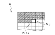
表示装置は、入力信号(表示データ)に基づく映像を表示部に表示する。入力信号は、画素Pi、jに映像を表示するための信号である。図32に示されるように、表示装置には、画素Pi−4、画素Pi−3、画素Pi−2、画素Pi−1、画素Pi、画素Pi+1、画素Pi+2、画素Pi+3に対応する入力信号(表示データ)が順次に入力される。ここで、iは任意の整数である。 The display device displays an image based on the input signal (display data) on the display unit. The input signal is a signal for displaying an image on the pixel Pi, j. As shown in FIG. 32, the display device includes input signals (pixel Pi-4, pixel Pi-3, pixel Pi-2, pixel Pi-1, pixel Pi, pixel Pi + 1, pixel Pi + 2, and pixel Pi + 3). Display data) are sequentially input. Here, i is an arbitrary integer.
表示装置は、表示データに応じた動画像を表示部に表示することができる。ここで、各画素は、1サブフィールドから構成され、1サブフィールドは、第1SF(サブフィールド)−第8SFを有する。各画素の第1SF−第8SFの各々には、R(赤)、G(緑)、B(青)の3色の色の濃さを示す階調レベルが設定されている。例えば、画素Piの第1SF−第8SFの各々に非点灯(黒)を表す階調レベルが設定されている場合、画素Piの階調レベルは、0を表す。対象画素として画素Piの第1SF−第8SFの少なくともいずれか1つに点灯(黒以外)を表す階調レベルが設定されている場合、画素Piの階調レベルは、1−255の範囲を表す。 The display device can display a moving image corresponding to the display data on the display unit. Here, each pixel is composed of one subfield, and one subfield has first SF (subfield) to eighth SF. In each of the first SF to the eighth SF of each pixel, gradation levels indicating the densities of the three colors R (red), G (green), and B (blue) are set. For example, when the gradation level indicating non-lighting (black) is set in each of the first SF to the eighth SF of the pixel Pi, the gradation level of the pixel Pi represents 0. When a gradation level representing lighting (other than black) is set in at least one of the first SF to the eighth SF of the pixel Pi as the target pixel, the gradation level of the pixel Pi represents a range of 1-255. .
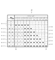
図32に示す例の場合、画素Pi−4、画素Pi−3、画素Pi−2、画素Pi−1の第1SF−第7SFには、点灯を表す階調レベル(図32の白表示)が設定され、画素Pi−4、画素Pi−3、画素Pi−2、画素Pi−1の第8SFには、非点灯を表す階調レベル(図32の黒表示)が設定されている。画素Pi、画素Pi+1、画素Pi+2、画素Pi+3の第1SF−第7SFには、非点灯を表す階調レベル(図32の黒表示)が設定され、画素Pi、画素Pi+1、画素Pi+2、画素Pi+3の第8SFには、点灯を表す階調レベル(図32の白表示)が設定されている。動画像が表示部に表示される場合、表示部の画素Pi−4、画素Pi−3、画素Pi−2、画素Pi−1に対応する位置に、第1SF−第7SF(点灯)、第8SF(非点灯)の順に表示データが表示される。また、表示部の画素Pi、画素Pi+1、画素Pi+2、画素Pi+3に対応する位置に、第1SF−第7SF(非点灯)、第8SF(点灯)の順に表示データが表示される。 In the case of the example shown in FIG. 32, the first SF to the seventh SF of the pixel Pi-4, the pixel Pi-3, the pixel Pi-2, and the pixel Pi-1 have gradation levels that indicate lighting (white display in FIG. 32). In the eighth SF of the pixel Pi-4, the pixel Pi-3, the pixel Pi-2, and the pixel Pi-1, a gradation level that represents non-lighting (black display in FIG. 32) is set. The first SF to the seventh SF of the pixel Pi, the pixel Pi + 1, the pixel Pi + 2, and the pixel Pi + 3 are set to the gradation level (black display in FIG. 32) indicating non-lighting, and the pixel Pi, the pixel Pi + 1, the pixel Pi + 2, and the pixel Pi + 3 In the eighth SF, a gradation level (white display in FIG. 32) indicating lighting is set. When a moving image is displayed on the display unit, the first SF, the seventh SF (lighted), and the eighth SF are located at positions corresponding to the pixel Pi-4, the pixel Pi-3, the pixel Pi-2, and the pixel Pi-1 of the display unit. Display data is displayed in the order of (not lit). Further, display data is displayed in the order of the first SF to the seventh SF (non-lighting) and the eighth SF (lighting) at positions corresponding to the pixel Pi, the pixel Pi + 1, the pixel Pi + 2, and the pixel Pi + 3 in the display unit.
表示部に表示された動画像をユーザが見たときに、図32に示されるように動画偽輪郭100が現われる。動画偽輪郭については、非特許文献1に記載されている。動画偽輪郭100が現われたとき、表示部に表示される静止画にも影響する。この動画偽輪郭100を低減することが望まれる。
When the user views the moving image displayed on the display unit, a moving image
動的な偽輪郭の発生が少なくて済む自発光表示パネルの駆動装置が知られている(特許文献1)。特許文献1に記載された技術によれば、自発光表示パネルをサブフィールド法で駆動して映像を階調表示するに際し、サブフィールド法による偽輪郭に基づいて映像の表示データを補正する。特許文献1に記載された技術では、判別手段と、補正選択手段とを備えたことを特徴としている。判別手段は、同一画素についてのフレーム間での変動と同一フレームについての画素間での変動とに基づいて画素ごとに偽輪郭発生の有無を判別する。補正選択手段は、この判別結果に応じて選択的に表示データの補正を行う。
A drive device for a self-luminous display panel that requires less generation of dynamic false contours is known (Patent Document 1). According to the technique described in
特許文献1の技術のように、単に、偽輪郭の発生の有無の判別結果に応じて選択的に表示データの補正を行うだけでは、偽輪郭発生の低減効果が十分でなかった。
As in the technique of
そのような課題に鑑みなされた従来の技術としては、例えば、特許文献2の技術がある。特許文献2には、対象画素毎に複数の候補画素信号を生成し、それら複数の候補画素信号のうち、最も偽輪郭強度が小さい候補画素信号を、表示動作用に選択する技術が開示されている。
本発明の課題は、従来技術よりも好適に動画偽輪郭を低減することができる動画偽輪郭低減方法、動画偽輪郭低減回路、表示装置及びプログラムを提供することにある。 An object of the present invention is to provide a moving image false contour reduction method, a moving image false contour reduction circuit, a display device, and a program that can reduce the moving image false contour more favorably than the prior art.
本発明の更に他の課題は、入力信号(表示データ)に応じた画像を従来技術よりも正確に表示することができる動画偽輪郭低減方法、動画偽輪郭低減回路、表示装置及びプログラムを提供することにある。 Still another object of the present invention is to provide a moving image false contour reduction method, a moving image false contour reduction circuit, a display device, and a program capable of displaying an image corresponding to an input signal (display data) more accurately than in the prior art. There is.
本発明の動画偽輪郭低減方法は、対象画素に映像を表示するための入力信号を入力し、該入力信号に基づいて対象画素に映像を表示した場合の前記対象画素における偽輪郭強度を検出する検出ステップと、前記検出ステップにより検出された偽輪郭強度のレベルに応じた態様で、前記入力信号に対して誤差拡散処理を施す誤差拡散ステップと、を備えることを特徴としている。 The moving image false contour reduction method of the present invention receives an input signal for displaying an image on the target pixel, and detects the false contour strength in the target pixel when the image is displayed on the target pixel based on the input signal. A detection step; and an error diffusion step of performing error diffusion processing on the input signal in a manner corresponding to the level of the false contour intensity detected by the detection step.
また、本発明の動画偽輪郭低減方法は、対象画素に映像を表示するための入力信号を入力し、該入力信号に応じて、複数のサブフィールドと複数の階調レベルとを対応付ける階調レベル設定メモリを参照して、複数の決定サブフィールドの階調レベルを、それらの階調レベルの合計値が前記対象画素の階調レベルとなるように決定する決定ステップと、前記決定サブフィールド毎に、前記対象画素と前記対象画素の周辺の周辺画素との輪郭を検出して輪郭検出値を生成するステップと、前記階調レベル設定メモリに格納された前記サブフィールドに対応する階調レベルを、前記決定サブフィールド毎に前記輪郭検出値に乗算して偽輪郭検出値を生成するステップと、前記決定サブフィールド毎に生成された前記偽輪郭検出値の合計値を、動画偽輪郭の程度を表す偽輪郭強度として算出するステップと、前記対象画素の階調レベルと前記偽輪郭強度と前記表示部に表示される前記対象画素の階調レベルを実際にユーザが見たときに感じる見た目の偽輪郭強度とを対応付ける視覚感度設定メモリを参照して、前記対象画素の階調レベルと前記偽輪郭強度とに対応する前記見た目の偽輪郭強度を検索する検索ステップと、前記検索ステップにより検索された前記見た目の偽輪郭強度のレベルに応じた態様で、前記入力信号に対して誤差拡散処理を施す誤差拡散ステップと、を備えることを特徴としている。 In addition, the moving image false contour reduction method of the present invention inputs an input signal for displaying an image on a target pixel, and associates a plurality of subfields with a plurality of gradation levels according to the input signal. Referring to the setting memory, a determination step of determining the gradation levels of the plurality of determination subfields so that the total value of the gradation levels becomes the gradation level of the target pixel, and for each determination subfield Detecting a contour between the target pixel and peripheral pixels around the target pixel to generate a contour detection value; and a gradation level corresponding to the subfield stored in the gradation level setting memory, A step of generating a false contour detection value by multiplying the contour detection value for each decision subfield, and a total value of the false contour detection values generated for each decision subfield, A step of calculating as a false contour intensity representing the degree of contour, a gradation level of the target pixel, the false contour strength, and a gradation level of the target pixel displayed on the display unit when the user actually sees A search step for searching for the apparent false contour strength corresponding to the gradation level of the target pixel and the false contour strength with reference to a visual sensitivity setting memory for associating the felt false contour strength with the felt appearance, and the search step And an error diffusion step of performing an error diffusion process on the input signal in a manner corresponding to the level of the apparent false contour strength retrieved by the above.
本発明の動画偽輪郭低減回路は、対象画素に映像を表示するための入力信号を入力し、該入力信号に基づいて対象画素に映像を表示した場合の前記対象画素における偽輪郭強度を検出する偽輪郭検出部と、前記偽輪郭検出部により検出された偽輪郭強度のレベルに応じた態様で、前記入力信号に対して誤差拡散処理を施す誤差拡散処理部と、前記誤差拡散処理部による誤差拡散処理後の入力信号に基づき映像が表示されるように表示部を制御する表示制御部と、を備えることを特徴としている。 The moving image false contour reduction circuit of the present invention receives an input signal for displaying an image on the target pixel, and detects the false contour strength in the target pixel when the image is displayed on the target pixel based on the input signal. A false contour detection unit, an error diffusion processing unit that performs error diffusion processing on the input signal in a manner corresponding to the level of the false contour intensity detected by the false contour detection unit, and an error caused by the error diffusion processing unit And a display control unit that controls the display unit so that an image is displayed based on the input signal after the diffusion processing.
また、本発明の動画偽輪郭低減回路は、複数のサブフィールドと複数の階調レベルとを対応付ける階調レベル設定メモリと、対象画素に映像を表示するための入力信号を入力し、該入力信号に応じて、前記階調レベル設定メモリを参照して、複数の決定サブフィールドの階調レベルを、それらの階調レベルの合計値が前記対象画素の階調レベルとなるように決定するコーディング部と、前記決定サブフィールド毎に、前記対象画素と前記対象画素の周辺の周辺画素との輪郭を検出して輪郭検出値を生成する輪郭検出部と、前記階調レベル設定メモリに格納された前記サブフィールドに対応する階調レベルを、前記決定サブフィールド毎に前記輪郭検出値に乗算して偽輪郭検出値を生成する重付部と、前記決定サブフィールド毎に生成された前記偽輪郭検出値の合計値を、動画偽輪郭の程度を表す偽輪郭強度として算出する加算部と、前記対象画素の階調レベルと前記偽輪郭強度と前記表示部に表示される前記対象画素の階調レベルを実際にユーザが見たときに感じる見た目の偽輪郭強度とを対応付ける視覚感度設定メモリと、前記視覚感度設定メモリを参照して、前記対象画素の階調レベルと前記偽輪郭強度とに対応する前記見た目の偽輪郭強度を検索する視覚感度変換部と、前記視覚感度変換部により検索された前記見た目の偽輪郭強度のレベルに応じた態様で、前記入力信号に対して誤差拡散処理を施す誤差拡散処理部と、前記誤差拡散処理部による誤差拡散処理後の入力信号に基づき映像が表示されるように表示部を制御する表示制御部と、を備えることを特徴としている。 The moving image false contour reduction circuit of the present invention receives a gradation level setting memory that associates a plurality of subfields with a plurality of gradation levels, an input signal for displaying an image on a target pixel, and the input signal. In accordance with the coding level, the coding unit that refers to the gradation level setting memory and determines the gradation levels of the plurality of determination subfields so that the total value of the gradation levels becomes the gradation level of the target pixel. And, for each decision subfield, a contour detection unit that detects a contour between the target pixel and peripheral pixels around the target pixel to generate a contour detection value, and the gradation level setting memory stores the contour detection value. A weighting unit for multiplying the contour detection value for each determined subfield by the gradation level corresponding to the subfield to generate a false contour detection value, and a pre-generated value for each determination subfield An adder that calculates a total value of false contour detection values as a false contour strength that represents the degree of the false contour of a moving image, a gradation level of the target pixel, the false contour strength, and the target pixel displayed on the display unit A visual sensitivity setting memory for associating an apparent false contour strength when the user actually sees the gradation level, and referring to the visual sensitivity setting memory, the gradation level of the target pixel and the false contour strength A visual sensitivity converter that searches for the apparent false contour strength corresponding to the visual sensitivity, and an error diffusion process for the input signal in a manner according to the level of the apparent false contour strength searched by the visual sensitivity converter And a display control unit for controlling the display unit so that an image is displayed based on an input signal after error diffusion processing by the error diffusion processing unit.
また、本発明の表示装置は、本発明の動画偽輪郭低減回路と、前記動画偽輪郭低減回路に接続された表示部と、を備えることを特徴としている。 The display device of the present invention includes the moving image false contour reduction circuit of the present invention and a display unit connected to the moving image false contour reduction circuit.
本発明のプログラムは、コンピュータが実行なプログラムであって、対象画素に映像を表示するための入力信号が入力されると、該入力信号に基づいて対象画素に映像を表示した場合の前記対象画素における偽輪郭強度を検出する検出処理と、前記検出処理により検出された偽輪郭強度のレベルに応じた態様で、前記入力信号に対して誤差拡散処理を施す誤差拡散処理と、を実行することを特徴としている。 The program of the present invention is a program executed by a computer, and when an input signal for displaying an image is input to the target pixel, the target pixel when the image is displayed on the target pixel based on the input signal Performing a detection process for detecting the false contour strength in the method and an error diffusion process for performing an error diffusion process on the input signal in a manner corresponding to the level of the false contour strength detected by the detection process. It is a feature.
また、本発明のプログラムは、コンピュータが実行なプログラムであって、対象画素に映像を表示するための入力信号が入力されると、該入力信号に応じて、複数のサブフィールドと複数の階調レベルとを対応付ける階調レベル設定メモリを参照して、複数の決定サブフィールドの階調レベルを、それらの階調レベルの合計値が前記対象画素の階調レベルとなるように決定する決定処理と、前記決定サブフィールド毎に、前記対象画素と前記対象画素の周辺の周辺画素との輪郭を検出して輪郭検出値を生成する処理と、前記階調レベル設定メモリに格納された前記サブフィールドに対応する階調レベルを、前記決定サブフィールド毎に前記輪郭検出値に乗算して偽輪郭検出値を生成する処理と、前記決定サブフィールド毎に生成された前記偽輪郭検出値の合計値を、動画偽輪郭の程度を表す偽輪郭強度として算出する処理と、前記対象画素の階調レベルと前記偽輪郭強度と前記表示部に表示される前記対象画素の階調レベルを実際にユーザが見たときに感じる見た目の偽輪郭強度とを対応付ける視覚感度設定メモリを参照して、前記対象画素の階調レベルと前記偽輪郭強度とに対応する前記見た目の偽輪郭強度を検索する検索処理と、前記検索処理により検索された前記見た目の偽輪郭強度のレベルに応じた態様で、前記入力信号に対して誤差拡散処理を施す誤差拡散処理と、を実行することを特徴としている。 The program of the present invention is a program executed by a computer, and when an input signal for displaying an image is input to a target pixel, a plurality of subfields and a plurality of gradations are generated according to the input signal. Determination processing for determining a gradation level of a plurality of determination subfields so that a total value of the gradation levels becomes a gradation level of the target pixel with reference to a gradation level setting memory that associates the levels with each other , For each determined subfield, detecting a contour between the target pixel and peripheral pixels around the target pixel to generate a contour detection value; and in the subfield stored in the gradation level setting memory A process of generating a false contour detection value by multiplying the corresponding gradation level by the contour detection value for each of the determined subfields; and the false generated for each of the determination subfields Processing for calculating the total value of the contour detection values as false contour strength representing the degree of moving image false contour, the gradation level of the target pixel, the false contour strength, and the gradation of the target pixel displayed on the display unit The apparent false contour strength corresponding to the gradation level of the target pixel and the false contour strength with reference to the visual sensitivity setting memory that associates the false contour strength of the visual felt when the user actually sees the level And an error diffusion process for performing an error diffusion process on the input signal in a manner corresponding to the apparent false contour strength level searched by the search process. It is said.
本発明の動画偽輪郭低減方法、動画偽輪郭低減回路、表示装置及びプログラムによれば、従来技術よりも好適に動画偽輪郭を低減することができる。 According to the moving image false contour reduction method, the moving image false contour reduction circuit, the display device, and the program of the present invention, it is possible to reduce the moving image false contour more favorably than the related art.
本発明の動画偽輪郭低減方法、動画偽輪郭低減回路、表示装置及びプログラムによれば、入力信号(表示データ)に応じた画像を正確に表示することができる。 According to the moving image false contour reduction method, the moving image false contour reduction circuit, the display device, and the program of the present invention, an image corresponding to an input signal (display data) can be accurately displayed.
添付図面を参照して、本発明による動画偽輪郭低減方法を実施するための最良の形態を以下に説明する。 With reference to the accompanying drawings, the best mode for carrying out the moving image false contour reducing method according to the present invention will be described below.
(第1実施形態)
本発明の第1実施形態に係る動画偽輪郭低減方法は、図1に示されるような表示装置10により実現される。図1は、本発明の第1実施形態に係る表示装置10の構成を示すブロック図である。本発明の第1実施形態に係る表示装置10は、動画偽輪郭低減回路1と、動画偽輪郭低減回路1に接続された表示部2とを具備する。表示部2としては、プラズマディスプレイが例示される。
(First embodiment)
The moving image false contour reducing method according to the first embodiment of the present invention is realized by a
表示部2は、マトリクス状に配列された複数の画素を有する。動画偽輪郭低減回路1には、画素Pi、jに映像を表示するための入力信号が表示データとして入力される。ここで、iは、表示部2の水平方向のアドレスを表す任意の整数であり、jは、表示部2の垂直方向のアドレスを表す任意の整数である。例えば、図2に示されるように、動画偽輪郭低減回路1には、画素Pi−4、j、画素Pi−3、j、画素Pi−2、j、画素Pi−1、j、画素Pi、j、画素Pi+1、j、画素Pi+2、j、画素Pi+3、jに対応する入力信号(表示データ)が順次に入力される。各画素が表示部2に表示されたとき、画素Pi−3、jは画素Pi−4、jに隣接し、画素Pi−2、jは画素Pi−3、jに隣接し、画素Pi−1、jは画素Pi−2、jに隣接し、画素Pi、jは画素Pi−1、jに隣接し、画素Pi+1、jは画素Pi、jに隣接し、画素Pi+2、jは画素Pi、j+1に隣接し、画素Pi+3、jは画素Pi、j+2に隣接する。
The
本発明の第1実施形態に係る表示装置10は、表示データを動画像として表示部2に表示することができる。ここで、各画素は、1サブフィールドから構成され、1サブフィールドは、第1SF(サブフィールド)−第nSFを有する。nは、例えば8以上の整数である。各画素の第1SF−第nSFの各々には、R(赤)、G(緑)、B(青)の3色の色の濃さを示す階調レベルが設定されている。例えば、画素Piの第1SF−第nSFの各々に非点灯(黒)を表す階調レベルが設定されている場合、画素Piの階調レベルは、0を表す。対象画素として画素Piの第1SF−第nSFの少なくともいずれか1つに点灯(黒以外)を表す階調レベルが設定されている場合、画素Piの階調レベルは、1−255の範囲を表す。
The
図2に示す例の場合、例えば、画素Pi−4、j、画素Pi−3、j、画素Pi−2、j、画素Pi−1、jの第1SF−第(m−1)SFには、点灯を表す階調レベル(図2の白表示)が設定され、画素Pi−4、j、画素Pi−3、j、画素Pi−2、j、画素Pi−1、jの第mSFには、非点灯を表す階調レベル(図2の黒表示)が設定され、画素Pi、j、画素Pi+1、j、画素Pi+2、j、画素Pi+3、jの第1SF−第(m−1)SFには、非点灯を表す階調レベル(図2の黒表示)が設定され、画素Pi、j、画素Pi+1、j、画素Pi+2、j、画素Pi+3、jの第mSFには、点灯を表す階調レベル(図2の白表示)が設定されている。 In the case of the example shown in FIG. 2, for example, the first SF- (m−1) SF of the pixel Pi-4, j, the pixel Pi-3, j, the pixel Pi-2, j, and the pixel Pi-1, j are , A gradation level indicating lighting (white display in FIG. 2) is set, and the mSF of each of the pixels Pi-4 and j, the pixels Pi-3 and j, the pixels Pi-2 and j, and the pixels Pi-1 and j , A gradation level indicating blackening (black display in FIG. 2) is set, and the first SF− (m−1) SF of the pixel Pi, j, pixel Pi + 1, j, pixel Pi + 2, j, pixel Pi + 3, j is set to Is set to a gradation level indicating blackening (black display in FIG. 2), and the mSF of pixels Pi, j, pixels Pi + 1, j, pixels Pi + 2, j, pixels Pi + 3, j has a gradation indicating lighting. The level (white display in FIG. 2) is set.
仮に、入力信号(表示データ)が動画偽輪郭低減回路1を介さないで表示部2に直接入力されて、動画像が表示部2に表示される場合、表示部2の画素Pi−4、j、画素Pi−3、j、画素Pi−2、j、画素Pi−1、jに対応する位置(アドレス)に、第1SF−第(m−1)SF(点灯)、第mSF(非点灯)の順に表示動作が行われる。また、表示部の画素Pi、j、画素Pi+1、j、画素Pi+2、j、画素Pi+3、jに対応する位置(アドレス)に、第1SF−第(m−1)SF(非点灯)、第mSF(点灯)の順に表示動作が行われる。
If an input signal (display data) is directly input to the
入力信号(表示データ)が動画偽輪郭低減回路1を介さないで表示部2に直接入力されて、動画像が表示部2に表示される場合、図2に示されるように、ユーザが動画像を見たときに、動画偽輪郭100が現われる。動画偽輪郭100が現われたとき、表示部2に表示される静止画にも影響する。
When an input signal (display data) is directly input to the
また、ユーザは、実際に対象画素Pi、jの階調レベルを表示部2により視認したときに、その階調レベルをより強く感じる場合がある。本発明の第1実施形態に係る動画偽輪郭低減方法では、ユーザが実際に見たときに感じる偽輪郭強度を考慮することにより、従来技術よりも正確に動画偽輪郭100を低減する。
Further, when the user actually visually recognizes the gradation level of the target pixel Pi, j on the
図1に示されるように、動画偽輪郭低減回路1は、複数の偽輪郭検出部3−1乃至3−n(nは2以上の整数)と、選択部4と、表示制御部5とを具備する。
As shown in FIG. 1, the moving image false
複数の偽輪郭検出部3−1乃至3−nは、対象画素である画素Pi、jに映像を表示するための入力信号を入力して、入力信号(画素Pi、j)に対して、それぞれ候補画素信号8−1乃至8−nを生成して選択部4に出力する。
The plurality of false contour detection units 3-1 to 3-n input an input signal for displaying an image to the pixel Pi, j that is the target pixel, and each of the input signals (pixels Pi, j) Candidate pixel signals 8-1 to 8-n are generated and output to the
複数の偽輪郭検出部3−1乃至3−nのうちの偽輪郭検出部3−1は、複数の候補画素信号8−1乃至8−nのうちの候補画素信号8−1を選択部4に出力する。候補画素信号8−1が表す階調レベルは、入力信号(画素Pi、j)の階調レベルを表す。この候補画素信号8−1が表す階調レベルは、候補画素信号8−1の第1SF−第mSFのうち、点灯(黒以外)を表す階調レベルが設定されたサブフィールドの階調レベルの合計値を表す。候補画素信号8−1には、見た目の動画偽輪郭の程度を表す偽輪郭強度f2が付されている。見た目の偽輪郭強度f2は、表示部2に表示される対象画素の階調レベルをユーザが実際に見たときに感じる偽輪郭強度である。
The false contour detection unit 3-1 among the plurality of false contour detection units 3-1 to 3-n selects the candidate pixel signal 8-1 from the plurality of candidate pixel signals 8-1 to 8-n as the
複数の偽輪郭検出部3−1乃至3−nのうちの偽輪郭検出部3−k(k=1、2、…、n)は、複数の候補画素信号8−1乃至8−nのうちの候補画素信号8−kを選択部4に出力する。候補画素信号8−kが表す階調レベルは、入力信号(画素Pi、j)の階調レベルを表す。この候補画素信号8−kが表す階調レベルは、候補画素信号8−kの第1SF−第mSFのうち、点灯(黒以外)を表す階調レベルが設定されたサブフィールドの階調レベルの合計値を表す。候補画素信号8−kにも、見た目の動画偽輪郭の程度を表す偽輪郭強度f2が付されている。
Among the plurality of false contour detection units 3-1 to 3-n, the false contour detection unit 3-k (k = 1, 2,..., N) is a plurality of candidate pixel signals 8-1 to 8-n. The candidate pixel signal 8-k is output to the
選択部4は、候補画素信号8−1乃至8−nの各々が有する偽輪郭強度f2の中から、最も小さい偽輪郭強度f2を有する候補画素信号を選択する。表示制御部5は、上記選択された候補画素信号が入力信号(画素Pi、j)として表示されるように表示部2を制御する。
The
本発明の第1実施形態に係る表示装置10によれば、動画偽輪郭低減回路1は、複数の候補画素信号8−1乃至8−nの各々が有する見た目の偽輪郭強度f2の中から、最も小さい見た目の偽輪郭強度f2を有する候補画素信号を選択し、上記選択された候補画素信号を入力信号(対象画素Pi、j)として表示部2に表示するため、見た目を考慮せずに単純に求められた偽輪郭強度f1を用いて偽輪郭低減を行う従来技術と比べて、より好適に動画偽輪郭100を低減することができる。即ち、本発明の第1実施形態に係る表示装置10によれば、表示部2に表示される画像(動画、静止画)の画質が劣化しない。
According to the
図1に示されるように、動画偽輪郭低減回路1は、更に、参照メモリ6と、階調レベル設定メモリ7とを具備する。
As shown in FIG. 1, the moving image false
図3に示されるように、参照メモリ6には、選択部4によって入力信号が格納されている。参照メモリ6に格納された入力信号は、周辺画素(画素Pi−4、j、画素Pi−3、j、画素Pi−2、j、画素Pi−1、j)に映像を表示するための入力信号である。この周辺画素(画素Pi−4、j、画素Pi−3、j、画素Pi−2、j、画素Pi−1、j)は、表示制御部5によって表示部2に表示された画素(図3の斜線部分)である。
As shown in FIG. 3, an input signal is stored in the
図4に示されるように、階調レベル設定メモリ7には、複数のサブフィールド(第1SF−第mSF)と複数の階調レベルとが対応付けられて格納されている。第1SF−第mSFの階調レベルの合計値は255である。
As shown in FIG. 4, the gradation
偽輪郭検出部3−kの構成について、図1−図6を用いて説明する。図1に示されるように、偽輪郭検出部3−kは、コーディング部11と、輪郭検出部12と、偽輪郭強度生成部13とを具備する。
The configuration of the false contour detection unit 3-k will be described with reference to FIGS. As illustrated in FIG. 1, the false contour detection unit 3-k includes a
偽輪郭検出部3−kのコーディング部11は、階調レベル設定メモリ7を参照して、複数の決定サブフィールド(第1SF−第mSF)を決定する。複数の決定サブフィールド(第1SF−第mSF)の階調レベルの合計値は、画素Pi、jの階調レベルを表す。
The
偽輪郭検出部3−kの輪郭検出部12は、参照メモリ6を参照して、決定サブフィールド毎(第1SF−第mSF)に、入力信号が表す対象画素(画素Pi、j)と対象画素(画素Pi、j)の周辺の周辺画素との輪郭を検出する。輪郭の検出としては、対象画素(画素Pi、j)と周辺画素とのレベル差の有無を調べる方法が例示される。
The
対象画素(画素Pi、j)と周辺画素とのレベル差の有無を調べる方法について簡単に説明する。周辺画素は、画素Pi、jに対して水平方向に隣接する画素Pi−1、jと、画素Pi、jに対して垂直方向に隣接する画素Pi、j−1とを含む。輪郭検出部12は、対象画素(画素Pi、j)と周辺画素とのレベル差を算出するためのフィルターを備えている。
A method for examining the presence or absence of a level difference between the target pixel (pixel Pi, j) and the surrounding pixels will be briefly described. The peripheral pixels include a pixel Pi-1, j that is adjacent to the pixel Pi, j in the horizontal direction and a pixel Pi, j-1 that is adjacent to the pixel Pi, j in the vertical direction. The
画素Pi、jと画素Pi−1、jとのレベル差を算出するとき、図5に示されるように、輪郭検出部12のフィルターは、決定サブフィールド毎(第1SF−第mSF)に、画素Pi−1、jのレベルに−1を乗じて、画素Pi、jのレベルに+1を乗じて、画素Pi、jのレベルと画素Pi−1、jのレベルとを加算する。
When calculating the level difference between the pixel Pi, j and the pixel Pi-1, j, as shown in FIG. 5, the filter of the
画素Pi、jと画素Pi、j−1とのレベル差を算出するとき、図5に示されるように、輪郭検出部12のフィルターは、決定サブフィールド毎(第1SF−第mSF)に、画素Pi、j−1のレベルに−1を乗じて、画素Pi、jのレベルに+1を乗じて、画素Pi、jのレベルと画素Pi、j−1のレベルとを加算する。
When the level difference between the pixel Pi, j and the pixel Pi, j-1 is calculated, as shown in FIG. 5, the filter of the
以下の説明では、輪郭検出部12は、画素Pi、jと画素Pi−1、jとのレベル差を算出したものとする。例えば、図2に示されるように、画素Pi、jと画素Pi−1、jとの第1SF−第mSFでは、レベル差101が生じている。動画偽輪郭100を低減するためには、このレベル差101が生じるサブフィールドの数が少ないことが好ましい。輪郭検出部12は、決定サブフィールド毎(第1SF−第mSF)に、画素Pi、jと画素Pi−1、jとのレベル差101の有無を表す輪郭検出値を生成する。
In the following description, it is assumed that the
偽輪郭検出部3−kの偽輪郭強度生成部13は、決定サブフィールド毎(第1SF−第mSF)に生成された輪郭検出値に基づいて、上記の見た目の偽輪郭強度f2を生成する。偽輪郭強度生成部13は、偽輪郭強度f2を有する入力信号(画素Pi、j)を候補画素信号8−kとして選択部4に出力する。
False contour detector 3-k in the false
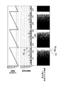
例えば、入力信号(表示データ)が動画偽輪郭低減回路1を介さないで表示部2に直接入力されて、動画像が表示部2に表示される場合、図6に示されるように、入力信号(表示データ)として画素Pi、jが有する偽輪郭強度f1102が他の偽輪郭強度f1よりも高いとき、動画偽輪郭100が現われる。本発明の第1実施形態に係る表示装置10によれば、動画偽輪郭低減回路1は、決定サブフィールド毎(第1SF−第mSF)に輪郭検出値を生成し、ユーザが実際に見たときに感じる偽輪郭強度を考慮した見た目の偽輪郭強度f2を求め、複数の候補画素信号8−1−8−nの各々が有する見た目の偽輪郭強度f2の中から、最も小さい偽輪郭強度f2を有する候補画素信号を選択し、上記選択された候補画素信号を入力信号(対象画素Pi、j)として表示部2に表示するため、見た目を考慮せずに単純に求めた偽輪郭強度f1を評価する判定で候補画素信号を選択し偽輪郭を低減する従来技術と比べて、より好適に動画偽輪郭100を低減することができる。本発明の第1実施形態に係る表示装置10によれば、動画偽輪郭100が低減するため、入力信号(表示データ)に応じた画像(動画、静止画)を表示部2に正確に表示することができる。
For example, when an input signal (display data) is directly input to the
偽輪郭検出部3−kの偽輪郭強度生成部13は、重付部14と、加算部15とを具備する。
The false contour
重付部14は、階調レベル設定メモリ7に格納された第1SF−第mSFに対応する階調レベルを、決定サブフィールド毎(第1SF−第mSF)に輪郭検出値に乗算して偽輪郭検出値を生成する。加算部15は、決定サブフィールド毎(第1SF−第mSF)に生成された偽輪郭検出値の合計値を偽輪郭強度f1として算出し、偽輪郭強度f1を有する入力信号(画素Pi、j)を偽輪郭検出部3−kの視覚感度変換部16に出力する。
The
図1に示されるように、動画偽輪郭低減回路1は、更に、視覚感度設定メモリ9を具備する。動画偽輪郭低減回路1の偽輪郭検出部3−kは、更に、視覚感度変換部16を具備する。
As shown in FIG. 1, the moving image false
図10に示されるように、視覚感度設定メモリ9には、対象画素の階調レベルと、偽輪郭強度f1と、見た目の偽輪郭強度f2とが対応付けられて格納されている。見た目の偽輪郭強度f2は、表示部2に表示される対象画素の階調レベルをユーザが実際に見たときに感じる偽輪郭強度である。
As shown in FIG. 10, the visual
偽輪郭検出部3−kの視覚感度変換部16は、視覚感度設定メモリ9を参照して、対象画素である画素Pi、jの階調レベルと偽輪郭強度f1とに対応する見た目の偽輪郭強度f2を検索し、検索された見た目の偽輪郭強度f2を有する入力信号(画素Pi、j)を候補画素信号8−kとして選択部4に出力する。
False contour detector 3-k visual
入力信号(対象画素)の階調レベルが表示部2に表示されたとき、ユーザは、その階調レベルを視認する。ユーザが対象画素の階調レベルを視認したときに感じる理想視覚感度は、図11に示される関数31により表される。関数31は、対象画素の階調レベルと、理想視覚感度との関係を表したものである。理想視覚感度は、対象画素の階調レベルに比例している。対象画素の階調レベルがAであるとき、理想視覚感度はa1で表され、対象画素の階調レベルBであるとき、理想視覚感度はb1で表される。階調レベルBは階調レベルAより高く、理想視覚感度b1は理想視覚感度a1より高い。
When the gradation level of the input signal (target pixel) is displayed on the
しかし、Weber−Fechnerの法則によると、実際にユーザが対象画素の階調レベルを視認したときに感じる視覚感度は、図11に示される関数32により表される。関数32は、対象画素の階調レベルと、実際にユーザが対象画素の階調レベルを視認したときに感じる視覚感度との関係を表したものである。Weber−Fechnerの法則については、S.Weitbruch、R.Zwing、C.Correa著「PDP Picture Quality Enhancement Based on Human Visual System Relevant Features」IDW、2000年11月29日、p.699−702に記載されている。対象画素の階調レベルがAであるとき、視覚感度はa2で表され、対象画素の階調レベルがBであるとき、視覚感度はb2で表される。視覚感度b2は視覚感度a2より高い。また、視覚感度a2は、上記の理想視覚感度a1より大幅に高く、視覚感度b2は上記の理想視覚感度b1よりもわずかに高い。即ち、対象画素の階調レベルがAである場合、ユーザは、実際に対象画素の階調レベルAを視認したときに、その階調レベルAを理想値(理想視覚感度)よりもはるかに強く感じる。
However, according to Weber-Fechner's law, the visual sensitivity that the user actually feels when visually recognizing the gradation level of the target pixel is expressed by the
図12に示されるように、関数31には、偽輪郭強度f1102に対応する視覚感度が重畳されるものと予想される。例えば、対象画素の階調レベルがA、C、Dであるとき、理想視覚感度はa1、c1、d1で表される。ここで、A<C<D、a1<c1<d1である。対象画素が偽輪郭強度f1102を有する場合、対象画素の階調レベルA、C、Dに対して、理想視覚感度はa1+f1、c1+f1、d1+f1で表される。ここで、a1+f1<c1+f1<d1+f1である。
As shown in FIG. 12, it is expected that the visual sensitivity corresponding to the false
Weber−Fechnerの法則を考慮した場合、対象画素の階調レベルがA、C、Dであるとき、理想視覚感度はa2、c2、d2で表される。ここで、a2<c2<d2である。対象画素が偽輪郭強度f1102を有し、Weber−Fechnerの法則を考慮した場合、対象画素の階調レベルA、C、Dに対して、視覚感度はa2+f2、c2+f3、d2+f4で表される。ここで、a2+f2<c2+f3<d2+f4である。視覚感度f2は、表示部2に表示される対象画素の階調レベルAをユーザが実際に見たときに感じる見た目の偽輪郭強度f2103に対応する。視覚感度f3は、表示部2に表示される対象画素の階調レベルCをユーザが実際に見たときに感じる見た目の偽輪郭強度f2104に対応する。視覚感度f4は、表示部2に表示される対象画素の階調レベルDをユーザが実際に見たときに感じる見た目の偽輪郭強度f2105に対応する。
In consideration of Weber-Fechner's law, when the gradation level of the target pixel is A, C, or D, the ideal visual sensitivity is represented by a 2 , c 2 , and d 2 . Here, a 2 <c 2 <d 2 . When the target pixel has a false
このように、入力信号(対象画素)が偽輪郭強度f1を有していても、対象画素の階調レベルによって、見た目の偽輪郭強度f2が異なる。このため、本発明の第1実施形態に係る表示装置10では、対象画素である画素Pi、jの階調レベルと偽輪郭強度f1とに対応する見た目の偽輪郭強度f2を決定する必要がある。
Thus, even if the input signal (target pixel) has the false contour strength f 1 , the apparent false contour strength f 2 varies depending on the gradation level of the target pixel. Therefore, in the
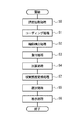
本発明の第1実施形態に係る表示装置10の動作について図7、図8、図9、図14を用いて説明する。
The operation of the
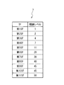
上記のmは、例えば11であるものとする(m=11)。例えば、階調レベル設定メモリ7には、第1SF、第2SF、第3SF、第4SF、第5SF、第6SF、第7SF、第8SF、第9SF、第10SF、第11SFに対応付けて、階調レベル“1”、“2”、“4”、“7”、“11”、“20”、“30”、“40”、“45”、“45”、“50”が格納されているものとする(図7参照)。また、対象画素である画素Pi、jに隣接する画素(周辺画素)として画素Pi−1、jの階調レベルは、4であり、画素Pi−1、jの第1SF、第2SF、第3SF、第4SF、第5SF、第6SF、第7SF、第8SF、第9SF、第10SF、第11SFの階調レベルは、“0”、“0”、“4”、“0”、“0”、“0”、“0”、“0”、“0”、“0”、“0”とする(図8、図9参照)。画素Pi、jの階調レベルは、11であるものとする。
For example, m is 11 (m = 11). For example, in the gradation
動画偽輪郭低減回路1には、表示データとして画素Pi、jに映像を表示するための入力信号が入力される。すると、動画偽輪郭低減回路1の偽輪郭検出部3−kのコーディング部11は、コーディング処理を実行する(図14のステップS1)。
The moving image false
コーディング処理では、偽輪郭検出部3−1のコーディング部11は、画素Pi、jの階調レベルが11であることを認識する。偽輪郭検出部3−1のコーディング部11は、階調レベル設定メモリ7を参照して、複数の決定サブフィールド(第1SF−第11SF)を決定する。複数の決定サブフィールド(第1SF−第11SF)の階調レベルの合計値は、画素Pi、jの階調レベル“11”を表す。決定サブフィールドである第1SF、第2SF、第3SF、第4SF、第5SF、第6SF、第7SF、第8SF、第9SF、第10SF、第11SFの階調レベルは、“0”、“0”、“4”、“7”、“0”、“0”、“0”、“0”、“0”、“0”、“0”である。偽輪郭検出部3−1のコーディング部11は、複数の決定サブフィールド(第1SF−第11SF)を入力信号(画素Pi、j)の第1SF−第11SFとして、偽輪郭検出部3−1の輪郭検出部12に出力する。
In the coding process, the
また、コーディング処理では、偽輪郭検出部3−2のコーディング部11は、画素Pi、jの階調レベルが11であることを認識する。偽輪郭検出部3−2のコーディング部11は、階調レベル設定メモリ7を参照して、複数の決定サブフィールド(第1SF−第11SF)を決定する。複数の決定サブフィールド(第1SF−第11SF)の階調レベルの合計値は、画素Pi、jの階調レベル“11”を表す。決定サブフィールドである第1SF、第2SF、第3SF、第4SF、第5SF、第6SF、第7SF、第8SF、第9SF、第10SF、第11SFの階調レベルは、“0”、“0”、“0”、“0”、“11”、“0”、“0”、“0”、“0”、“0”、“0”である。偽輪郭検出部3−2のコーディング部11は、複数の決定サブフィールド(第1SF−第11SF)を入力信号(画素Pi、j)の第1SF−第11SFとして、偽輪郭検出部3−2の輪郭検出部12に出力する。
In the coding process, the
次に、動画偽輪郭低減回路1の偽輪郭検出部3−kの輪郭検出部12は、輪郭検出処理を実行する(図14のステップS2)。
Next, the
輪郭検出処理では、偽輪郭検出部3−1の輪郭検出部12は、参照メモリ6を参照して、決定サブフィールド毎(第1SF−第11SF)に、偽輪郭検出部3−1のコーディング部11からの入力信号が表す画素Pi、jと、画素Pi、jに隣接する画素とのレベル差の有無を調べる。図8に示されるように、画素Pi、jの第4SFと、画素Pi、jに隣接する画素Pi−1、jの第4SFとには、レベル差が生じる。偽輪郭検出部3−1の輪郭検出部12は、画素Pi、jと画素Pi−1、jとの第4SFにレベル差が有ることを表す輪郭検出値“1”を生成する。一方、画素Pi、jの第1SF−第3SF、第5SF−第11SFと、画素Pi−1、jの第1SF−第3SF、第5SF−第11SFとには、レベル差が生じない。偽輪郭検出部3−1の輪郭検出部12は、画素Pi、jと画素Pi−1、jとの第1SF−第3SF、第5SF−第11SFにレベル差が無いことを表す輪郭検出値“0”を生成する。偽輪郭検出部3−1の輪郭検出部12は、第1SF、第2SF、第3SF、第4SF、第5SF、第6SF、第7SF、第8SF、第9SF、第10SF、第11SFに対して輪郭検出値“0”、“0”、“0”、“1”、“0”、“0”、“0”、“0”、“0”、“0”、“0”を有する入力信号(画素Pi、j)を、偽輪郭検出部3−1の重付部14に出力する。
In the contour detection process, the
また、輪郭検出処理では、偽輪郭検出部3−2の輪郭検出部12は、参照メモリ6を参照して、決定サブフィールド毎(第1SF−第11SF)に、偽輪郭検出部3−2のコーディング部11からの入力信号が表す画素Pi、jと、画素Pi、jに隣接する画素とのレベル差の有無を調べる。図9に示されるように、画素Pi、jの第3SF、第5SFと、画素Pi、jに隣接する画素Pi−1、jの第3SF、第5SFとには、レベル差が生じる。偽輪郭検出部3−2の輪郭検出部12は、画素Pi、jと画素Pi−1、jとの第3SF、第5SFにレベル差が有ることを表す輪郭検出値“1”を生成する。一方、画素Pi、jの第1SF、第2SF、第4SF、第6SF−第11SFと、画素Pi−1、jの第1SF、第2SF、第4SF、第6SF−第11SFとには、レベル差が生じない。偽輪郭検出部3−2の輪郭検出部12は、画素Pi、jと画素Pi−1、jとの第1SF、第2SF、第4SF、第6SF−第11SFにレベル差が無いことを表す輪郭検出値“0”を生成する。偽輪郭検出部3−2の輪郭検出部12は、第1SF、第2SF、第3SF、第4SF、第5SF、第6SF、第7SF、第8SF、第9SF、第10SF、第11SFに対して輪郭検出値“0”、“0”、“1”、“0”、“1”、“0”、“0”、“0”、“0”、“0”、“0”を有する入力信号(画素Pi、j)を、偽輪郭検出部3−2の重付部14に出力する。
In the contour detection process, the
次に、動画偽輪郭低減回路1の偽輪郭検出部3−kの重付部14は、重付処理を実行する(図14のステップS3)。
Next, the
重付処理では、偽輪郭検出部3−1の重付部14は、階調レベル設定メモリ7を参照して、偽輪郭検出部3−1の輪郭検出部12からの入力信号(画素Pi、j)の第1SF、第2SF、第3SF、第4SF、第5SF、第6SF、第7SF、第8SF、第9SF、第10SF、第11SFに対する輪郭検出値“0”、“0”、“0”、“1”、“0”、“0”、“0”、“0”、“0”、“0”、“0”に、重み付けとして階調レベル“1”、“2”、“4”、“7”、“11”、“20”、“30”、“40”、“45”、“45”、“50”を乗じて、偽輪郭検出値“0”、“0”、“0”、“7”、“0”、“0”、“0”、“0”、“0”、“0”、“0”を生成する(図8参照)。偽輪郭検出部3−1の重付部14は、第1SF、第2SF、第3SF、第4SF、第5SF、第6SF、第7SF、第8SF、第9SF、第10SF、第11SFに対して偽輪郭検出値“0”、“0”、“0”、“7”、“0”、“0”、“0”、“0”、“0”、“0”、“0”を有する入力信号(画素Pi、j)を、偽輪郭検出部3−1の加算部15に出力する。
In the weighting process, the
また、重付処理では、偽輪郭検出部3−2の重付部14は、階調レベル設定メモリ7を参照して、偽輪郭検出部3−2の輪郭検出部12からの入力信号(画素Pi、j)の第1SF、第2SF、第3SF、第4SF、第5SF、第6SF、第7SF、第8SF、第9SF、第10SF、第11SFに対する輪郭検出値“0”、“0”、“1”、“0”、“1”、“0”、“0”、“0”、“0”、“0”、“0”に、重み付けとして階調レベル“1”、“2”、“4”、“7”、“11”、“20”、“30”、“40”、“45”、“45”、“50”を乗じて、偽輪郭検出値“0”、“0”、“4”、“0”、“11”、“0”、“0”、“0”、“0”、“0”、“0”を生成する(図9参照)。偽輪郭検出部3−2の重付部14は、第1SF、第2SF、第3SF、第4SF、第5SF、第6SF、第7SF、第8SF、第9SF、第10SF、第11SFに対して偽輪郭検出値“0”、“0”、“4”、“0”、“11”、“0”、“0”、“0”、“0”、“0”、“0”を有する入力信号(画素Pi、j)を、偽輪郭検出部3−2の加算部15に出力する。
In the weighting process, the
次に、動画偽輪郭低減回路1の偽輪郭検出部3−kの加算部15は、加算処理を実行する(図14のステップS4)。
Next, the
加算処理では、偽輪郭検出部3−1の加算部15は、偽輪郭検出部3−1の重付部14からの入力信号(画素Pi、j)の第1SF、第2SF、第3SF、第4SF、第5SF、第6SF、第7SF、第8SF、第9SF、第10SF、第11SFに対する偽輪郭検出値“0”、“0”、“0”、“7”、“0”、“0”、“0”、“0”、“0”、“0”、“0”の合計値を算出し、その合計値を表す偽輪郭強度f1“7”を生成する。偽輪郭検出部3−1の加算部15は、偽輪郭強度f1“7”を有する入力信号(画素Pi、j)を偽輪郭検出部3−1の視覚感度変換部16に出力する。
In the addition process, the
また、加算処理では、偽輪郭検出部3−2の加算部15は、偽輪郭検出部3−2の重付部14からの入力信号(画素Pi、j)の第1SF、第2SF、第3SF、第4SF、第5SF、第6SF、第7SF、第8SF、第9SF、第10SF、第11SFに対する偽輪郭検出値“0”、“0”、“4”、“0”、“11”、“0”、“0”、“0”、“0”、“0”、“0”の合計値を算出し、その合計値を表す偽輪郭強度f1“15”を生成する。偽輪郭検出部3−1の加算部15は、偽輪郭強度f1“15”を有する入力信号(画素Pi、j)を偽輪郭検出部3−2の視覚感度変換部16に出力する。
In addition, in the addition process, the
次に、動画偽輪郭低減回路1の偽輪郭検出部3−kの視覚感度変換部16は、視覚感度変換処理を実行する(図14のステップS7)。
Next, the visual
視覚感度変換処理では、偽輪郭検出部3−1の視覚感度変換部16は、視覚感度設定メモリ9を参照して、画素Pi、jの階調レベルと偽輪郭強度f1“7”とに対応する見た目の偽輪郭強度f2を検索し、検索された見た目の偽輪郭強度f2を有する入力信号(画素Pi、j)を候補画素信号8−1として選択部4に出力する。
In the visual sensitivity conversion process, the visual
また、視覚感度変換処理では、偽輪郭検出部3−2の視覚感度変換部16は、視覚感度設定メモリ9を参照して、画素Pi、jの階調レベルと偽輪郭強度f1“15”とに対応する見た目の偽輪郭強度f2を検索し、検索された見た目の偽輪郭強度f2を有する入力信号(画素Pi、j)を候補画素信号8−2として選択部4に出力する。
In the visual sensitivity conversion process, the visual
次に、動画偽輪郭低減回路1の選択部4は、選択処理を実行する(図14のステップS5)。
Next, the
選択処理では、選択部4は、候補画素信号8−1、8−2が有する偽輪郭強度f2の中から、最も小さい偽輪郭強度f2を有する候補画素信号8−1を選択する。選択部4は、候補画素信号8−1を表示制御部5に出力する共に、候補画素信号8−1を、周辺画素(画素Pi、j)に映像を表示するための入力信号として参照メモリ6に格納する。
In the selection process, the
次に、動画偽輪郭低減回路1の表示制御部5は、表示処理を実行する(図14のステップS6)。
Next, the
表示処理では、表示制御部5は、選択部4によって選択された候補画素信号8−1を入力し、階調レベル“11”を表す候補画素信号8−1が入力信号(画素Pi、j)として表示されるように表示部2を制御する。
In the display process, the
以上の説明により、ユーザは、実際に対象画素Pi、jの階調レベルを表示部2により視認したときに、その階調レベルをより強く感じる場合があるが、本発明の第1実施形態に係る表示装置10によれば、動画偽輪郭低減回路1は、決定サブフィールド毎(第1SF−第11SF)に輪郭検出値を生成するとともに、対象画素Pi、jの階調レベルと偽輪郭強度f1とに対応する見た目の偽輪郭強度f2を決定し、複数の候補画素信号8−1乃至8−11の各々が有する偽輪郭強度f2の中から、最も小さい偽輪郭強度f2を有する候補画素信号8−1を選択し、上記選択された候補画素信号8−1を入力信号(対象画素Pi、j)として表示部2に表示する。このため、本発明の第1実施形態に係る表示装置10によれば、従来技術よりも正確に動画偽輪郭100を低減することができる。
According to the above description, the user may feel the gradation level stronger when the gradation level of the target pixel Pi, j is actually visually recognized by the
本発明の第1実施形態に係る表示装置10によれば、動画偽輪郭100が低減するため、入力信号(表示データ)に応じた画像(動画、静止画)を表示部2に正確に表示することができる。
According to the
なお、本発明の第1実施形態に係る表示装置10では、表示データとして画素Pi、jに映像を表示するための入力信号が順次に動画偽輪郭低減回路1に入力されているが、これに限定されない。動画偽輪郭低減回路1は、表示データとして各画素に映像を表示するための入力信号を入力して参照メモリ6に格納し、3×3画素について上記のコーディング処理(ステップS1)、輪郭検出処理(ステップS2)、重付処理(ステップS3)、加算処理(ステップS4)、選択処理(ステップS5)、視覚感度変換処理(ステップS7)、表示処理(ステップS6)を実行することができる。この場合、対象画素を画素Pi、jとしたとき、周辺画素は、画素Pi−1、j−1、Pi、j−1、Pi−1、j−1、Pi−1、j、Pi+1、j、Pi−1、j+1、Pi、j+1、Pi−1、j+1である。
In the
(第2実施形態)
複数のサブフィールド(第1SF−第mSF)の各々の階調レベル(重み)は、第1SF−第mSFの順に徐々に高くなっている。そのため、第1実施形態と同じように上記のmを11個とした場合、例えば、対象画素Pi、jと周辺画素Pi−1、jとの第6SF−第11SFのレベル差によって動画偽輪郭100が強く現われる可能性がある。本発明の第2実施形態に係る動画偽輪郭低減方法では、入力信号(画素Pi、j)の階調レベルに対して、点灯(黒以外)を表す階調レベルが設定されたサブフィールド群を予めに決めておくことにより、第1実施形態よりも正確に動画偽輪郭100を低減する。本発明の第2実施形態に係る動画偽輪郭低減方法について説明する。
(Second Embodiment)
The gradation levels (weights) of the plurality of subfields (first SF-mth SF) are gradually increased in the order of first SF-mth SF. Therefore, when the above m is 11 as in the first embodiment, for example, the moving image
本発明の動画偽輪郭低減方法は、図15に示されるような表示装置10により実現される。図15は、本発明の第2実施形態に係る表示装置10の構成を示すブロック図である。第2実施形態では、第1実施形態と同じ構成については同符合を付している。本発明の第2実施形態に係る表示装置10の動画偽輪郭低減回路1は、更に、候補階調設定メモリ18、範囲選択メモリ19を具備する。動画偽輪郭低減回路1は、更に、誤差拡散部17を具備する。誤差拡散部17は、対象画素Pi、jに映像を表示するための入力信号を入力して、候補階調設定メモリ18を参照して、後述の候補サブフィールド群を含む入力信号(対象画素Pi、j)を複数の偽輪郭検出部3−1乃至3−nに出力する。
The moving image false contour reducing method of the present invention is realized by a
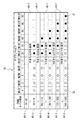
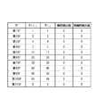
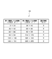
図16に示されるように、候補階調設定メモリ18には、複数の階調レベル範囲40−1乃至40−7と、複数のサブフィールド(第1SF−第mSF)とが対応付けられて格納されている。第1実施形態と同じように、上記のmは11個であるものとする(m=11)。候補階調設定メモリ18に格納された第1SF、第2SF、第3SF、第4SF、第5SF、第6SF、第7SF、第8SF、第9SF、第10SF、第11SFは、階調レベル“1”、“2”、“4”、“7”、“11”、“20”、“30”、“40”、“45”、“45”、“50”を表す。
As shown in FIG. 16, in the candidate
複数の階調レベル範囲40−1乃至40−7のうち、階調レベル範囲40−1は、階調レベル“0−45”の範囲を表す。入力信号(画素Pi、j)の階調レベルが階調レベル範囲40−1に含まれる場合、その階調レベルは比較的低いため、点灯(黒以外)を表す階調レベルが設定されたサブフィールド群(第1決定サブフィールド群21)を予めに決めておく必要はない。即ち、階調レベル範囲40−1に対応する第1決定サブフィールド群21を候補階調設定メモリ18に設定しておく必要はない。この場合、誤差拡散部17は、候補階調設定メモリ18を参照して、入力信号(対象画素Pi、j)を複数の偽輪郭検出部3−1−3−nに出力する。偽輪郭検出部3−kのコーディング部11は、第1実施形態と同様に上述の複数の決定サブフィールド(第1SF−第11SF)を決定する。
Among the plurality of gradation level ranges 40-1 to 40-7, the gradation level range 40-1 represents a range of gradation levels “0-45”. When the gradation level of the input signal (pixel Pi, j) is included in the gradation level range 40-1, since the gradation level is relatively low, the sub level to which the gradation level representing lighting (other than black) is set is set. It is not necessary to determine the field group (first determination subfield group 21) in advance. That is, it is not necessary to set the first
複数の階調レベル範囲40−1乃至40−7のうち、階調レベル範囲40−2は、階調レベル“56−75”の範囲を表す。入力信号(画素Pi、j)の階調レベルが階調レベル範囲40−2に含まれる場合、点灯(黒以外)を表す階調レベルが設定されたサブフィールド群として第6SF、第7SFを予めに決めておく。即ち、階調レベル範囲40−2に対応する第1決定サブフィールド群21として第6SF、第7SFを候補階調設定メモリ18に設定しておく。この場合、誤差拡散部17は、候補階調設定メモリ18を参照して、複数のサブフィールド(第1SF−第11SF)のうち、階調レベル範囲40−2に対応する候補サブフィールド群(第1SF−第7SF)を決定し、候補サブフィールド群(第1SF−第7SF)を含む入力信号(対象画素Pi、j)を複数の偽輪郭検出部3−1−3−nに出力する。この候補サブフィールド群(第1SF−第7SF)は、第1決定サブフィールド群21(第6SF、第7SF)と、選択候補サブフィールド群22である第1SF−第5SFとを含む。偽輪郭検出部3−kのコーディング部11は、この候補サブフィールド群(第1SF−第7SF)により、上述の複数の決定サブフィールド(第1SF−第11SF)を決定する。
Among the plurality of gradation level ranges 40-1 to 40-7, the gradation level range 40-2 represents a range of gradation levels “56-75”. When the gradation level of the input signal (pixel Pi, j) is included in the gradation level range 40-2, the sixth SF and the seventh SF are preliminarily set as subfield groups in which gradation levels representing lighting (other than black) are set. Decide on. That is, the sixth SF and the seventh SF are set in the candidate
複数の階調レベル範囲40−1乃至40−7のうち、階調レベル範囲40−3は、階調レベル“96−115”の範囲を表す。入力信号(画素Pi、j)の階調レベルが階調レベル範囲40−3に含まれる場合、第1決定サブフィールド群21として第6SF−第8SFを予めに決めておく。即ち、階調レベル範囲40−3に対応する第1決定サブフィールド群21として第6SF−第8SFを候補階調設定メモリ18に設定しておく。この場合、誤差拡散部17は、候補階調設定メモリ18を参照して、複数のサブフィールド(第1SF−第11SF)のうち、階調レベル範囲40−3に対応する候補サブフィールド群(第1SF−第8SF)を決定し、候補サブフィールド群(第1SF−第8SF)を含む入力信号(対象画素Pi、j)を複数の偽輪郭検出部3−1乃至3−nに出力する。この候補サブフィールド群(第1SF−第8SF)は、第1決定サブフィールド群21(第6SF−第8SF)と、選択候補サブフィールド群22である第1SF−第5SFとを含む。偽輪郭検出部3−kのコーディング部11は、この候補サブフィールド群(第1SF−第8SF)により、上述の複数の決定サブフィールド(第1SF−第11SF)を決定する。
Among the plurality of gradation level ranges 40-1 to 40-7, the gradation level range 40-3 represents the range of the gradation level “96-115”. When the gradation level of the input signal (pixel Pi, j) is included in the gradation level range 40-3, the sixth SF to the eighth SF are determined in advance as the first
複数の階調レベル範囲40−1乃至40−7のうち、階調レベル範囲40−4は、階調レベル“141−160”の範囲を表す。入力信号(画素Pi、j)の階調レベルが階調レベル範囲40−4に含まれる場合、第1決定サブフィールド群21として第6SF−第9SFを予めに決めておく。即ち、階調レベル範囲40−4に対応する第1決定サブフィールド群21として第6SF−第9SFを候補階調設定メモリ18に設定しておく。この場合、誤差拡散部17は、候補階調設定メモリ18を参照して、複数のサブフィールド(第1SF−第11SF)のうち、階調レベル範囲40−4に対応する候補サブフィールド群(第1SF−第9SF)を決定し、候補サブフィールド群(第1SF−第9SF)を含む入力信号(対象画素Pi、j)を複数の偽輪郭検出部3−1乃至3−nに出力する。この候補サブフィールド群(第1SF−第9SF)は、第1決定サブフィールド群21(第6SF−第9SF)と、選択候補サブフィールド群22である第1SF−第5SFとを含む。偽輪郭検出部3−kのコーディング部11は、この候補サブフィールド群(第1SF−第9SF)により、上述の複数の決定サブフィールド(第1SF−第11SF)を決定する。
Among the plurality of gradation level ranges 40-1 to 40-7, the gradation level range 40-4 represents the range of the gradation level “141-160”. When the gradation level of the input signal (pixel Pi, j) is included in the gradation level range 40-4, the sixth SF to the ninth SF are determined in advance as the first
複数の階調レベル範囲40−1乃至40−7のうち、階調レベル範囲40−5は、階調レベル“176−205”の範囲を表す。入力信号(画素Pi、j)の階調レベルが階調レベル範囲40−5に含まれる場合、第1決定サブフィールド群21として第7SF−第10SFを予めに決めておく。即ち、階調レベル範囲40−5に対応する第1決定サブフィールド群21として第7SF−第10SFを候補階調設定メモリ18に設定しておく。この場合、誤差拡散部17は、候補階調設定メモリ18を参照して、複数のサブフィールド(第1SF−第11SF)のうち、階調レベル範囲40−5に対応する候補サブフィールド群(第1SF−第10SF)を決定し、候補サブフィールド群(第1SF−第10SF)を含む入力信号(対象画素Pi、j)を複数の偽輪郭検出部3−1乃至3−nに出力する。この候補サブフィールド群(第1SF−第10SF)は、第1決定サブフィールド群21(第7SF−第10SF)と、選択候補サブフィールド群22である第1SF−第6SFとを含む。偽輪郭検出部3−kのコーディング部11は、この候補サブフィールド群(第1SF−第10SF)により、上述の複数の決定サブフィールド(第1SF−第11SF)を決定する。
Among the plurality of gradation level ranges 40-1 to 40-7, the gradation level range 40-5 represents the range of the gradation level “176-205”. When the gradation level of the input signal (pixel Pi, j) is included in the gradation level range 40-5, the seventh SF to the tenth SF are determined in advance as the first
複数の階調レベル範囲40−1乃至40−7のうち、階調レベル範囲40−6は、階調レベル“216−255”の範囲を表す。入力信号(画素Pi、j)の階調レベルが階調レベル範囲40−6に含まれる場合、第1決定サブフィールド群21として第8SF−第11SFを予めに決めておく。即ち、階調レベル範囲40−6に対応する第1決定サブフィールド群21として第8SF−第11SFを候補階調設定メモリ18に設定しておく。この場合、誤差拡散部17は、候補階調設定メモリ18を参照して、複数のサブフィールド(第1SF−第11SF)のうち、階調レベル範囲40−6に対応する候補サブフィールド群(第1SF−第11SF)を決定し、候補サブフィールド群(第1SF−第11SF)を含む入力信号(対象画素Pi、j)を複数の偽輪郭検出部3−1乃至3−nに出力する。この候補サブフィールド群(第1SF−第11SF)は、第1決定サブフィールド群21(第8SF−第11SF)と、選択候補サブフィールド群22である第1SF−第7SFとを含む。偽輪郭検出部3−kのコーディング部11は、この候補サブフィールド群(第1SF−第11SF)により、上述の複数の決定サブフィールド(第1SF−第11SF)を決定する。
Among the plurality of gradation level ranges 40-1 to 40-7, the gradation level range 40-6 represents a range of gradation levels “216-255”. When the gradation level of the input signal (pixel Pi, j) is included in the gradation level range 40-6, the eighth SF to the eleventh SF are determined in advance as the first
複数の階調レベル範囲40−1乃至40−7のうち、階調レベル範囲40−7は、階調レベル範囲40−1乃至40−6以外の範囲を表す。 Among the plurality of gradation level ranges 40-1 to 40-7, the gradation level range 40-7 represents a range other than the gradation level ranges 40-1 to 40-6.
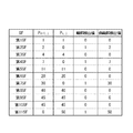
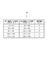
図17に示されるように、範囲選択メモリ19には、第1階調レベル範囲と、第2階調レベル範囲と、第1階調レベル範囲と第2階調レベル範囲との一方を選択するための選択情報とが対応付けられて格納されている。第1階調レベル範囲として階調レベル範囲40−q(q=1、2、3、4、5)はフラグ“0”を表し、第2階調レベル範囲として階調レベル範囲40−(q+1)はフラグ“1”を表す。選択情報は、フラグ“0”又は“1”を表す。
As shown in FIG. 17, the
例えば、誤差拡散部17は、候補階調設定メモリ18を参照して、入力信号(画素Pi、j)の階調レベルが階調レベル範囲40−5と階調レベル範囲40−6との間の階調レベル範囲40−7に含まれる場合、更に、範囲選択メモリ19を参照する。
For example, the
第1階調レベル範囲(階調レベル範囲40−5)と第2階調レベル範囲(階調レベル範囲40−6)とに対応する選択情報が表すフラグが“0”であるとき、誤差拡散部17は、入力信号(対象画素Pi、j)の階調レベルを、擬似階調レベルとして、階調レベル範囲40−5が表す階調レベル“176−205”の上限値である階調レベル“205”に設定し、階調レベル範囲40−5を選択する。誤差拡散部17は、階調レベル範囲40−5を選択した場合、複数のサブフィールド(第1SF−第10SF)のうち、階調レベル範囲40−5に対応する候補サブフィールド群(第1SF−第10SF)を決定する。この場合、誤差拡散部17は、候補サブフィールド群(第1SF−第10SF)を含む入力信号(対象画素Pi、j)を複数の偽輪郭検出部3−1乃至3−nに出力する。誤差拡散部17により出力された入力信号(対象画素Pi、j)の階調レベルは、205を表す。
When the flag represented by the selection information corresponding to the first gradation level range (gradation level range 40-5) and the second gradation level range (gradation level range 40-6) is “0”, error diffusion is performed. The
第1階調レベル範囲(階調レベル範囲40−5)と第2階調レベル範囲(階調レベル範囲40−6)とに対応する選択情報が表すフラグが“1”であるとき、誤差拡散部17は、入力信号(対象画素Pi、j)の階調レベルを、擬似階調レベルとして、階調レベル範囲40−6が表す階調レベル“216−255”の下限値である階調レベル“216”に設定し、階調レベル範囲40−6を選択する。誤差拡散部17は、階調レベル範囲40−6を選択した場合、複数のサブフィールド(第1SF−第11SF)のうち、階調レベル範囲40−6に対応する候補サブフィールド群(第1SF−第11SF)を決定する。この場合、誤差拡散部17は、候補サブフィールド群(第1SF−第10SF)を含む入力信号(対象画素Pi、j)を複数の偽輪郭検出部3−1乃至3−nに出力する。誤差拡散部17により出力された入力信号(対象画素Pi、j)の階調レベルは、216を表す。
When the flag represented by the selection information corresponding to the first gradation level range (gradation level range 40-5) and the second gradation level range (gradation level range 40-6) is “1”, error diffusion is performed. The
本発明の第2実施形態に係る表示装置10の動作について図7、図15−図23を用いて説明する。
The operation of the
第1実施形態と同じように、階調レベル設定メモリ7には、第1SF、第2SF、第3SF、第4SF、第5SF、第6SF、第7SF、第8SF、第9SF、第10SF、第11SFに対応付けて、階調レベル“1”、“2”、“4”、“7”、“11”、“20”、“30”、“40”、“45”、“45”、“50”が格納されているものとする(図7参照)。
As in the first embodiment, the gradation
本発明の第2実施形態に係る表示装置10の動作の説明として(A)の場合と、(B−1)の場合と、(B−2)の場合とを例にする。
As an explanation of the operation of the
(A)の場合では、入力信号(画素Pi、j)の階調レベルが階調レベル範囲40−2に含まれ、誤差拡散部17が、候補サブフィールド群(第1SF−第7SF)を含む入力信号(対象画素Pi、j)を複数の偽輪郭検出部3−1−3−nに出力する。
In the case of (A), the gradation level of the input signal (pixel Pi, j) is included in the gradation level range 40-2, and the
(B−1)の場合では、入力信号(画素Pi、j)の階調レベルが階調レベル範囲40−5と階調レベル範囲40−6との間の階調レベル範囲40−7に含まれる。誤差拡散部17が、階調レベル範囲40−5と階調レベル範囲40−6とのうちの階調レベル範囲40−5を選択し、候補サブフィールド群(第1SF−第10SF)を含む入力信号(対象画素Pi、j)を複数の偽輪郭検出部3−1−3−nに出力する。
In the case of (B-1), the gradation level of the input signal (pixel Pi, j) is included in the gradation level range 40-7 between the gradation level range 40-5 and the gradation level range 40-6. It is. The
(B−2)の場合では、入力信号(画素Pi、j)の階調レベルが階調レベル範囲40−5と階調レベル範囲40−6との間の階調レベル範囲40−7に含まれる。誤差拡散部17が、階調レベル範囲40−5と階調レベル範囲40−6とのうちの階調レベル範囲40−6を選択し、候補サブフィールド群(第1SF−第11SF)を含む入力信号(対象画素Pi、j)を複数の偽輪郭検出部3−1−3−nに出力する。
In the case of (B-2), the gradation level of the input signal (pixel Pi, j) is included in the gradation level range 40-7 between the gradation level range 40-5 and the gradation level range 40-6. It is. The
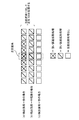
上記(A)の場合について説明する。対象画素である画素Pi、jに隣接する画素(周辺画素)として画素Pi−1、jの階調レベルは、56であり、画素Pi−1、jの第1SF、第2SF、第3SF、第4SF、第5SF、第6SF、第7SF、第8SF、第9SF、第10SF、第11SFの階調レベルは、“0”、“2”、“4”、“0”、“0”、“20”、“30”、“0”、“0”、“0”、“0”とする(図19、図20参照)。画素Pi、jの階調レベルは、57であるものとする。 The case (A) will be described. As a pixel (peripheral pixel) adjacent to the pixel Pi, j that is the target pixel, the gradation level of the pixel Pi-1, j is 56, and the first SF, second SF, third SF, and second of the pixel Pi-1, j The gradation levels of 4SF, 5th SF, 6th SF, 7th SF, 8th SF, 9th SF, 10th SF, and 11th SF are “0”, “2”, “4”, “0”, “0”, “20” ”,“ 30 ”,“ 0 ”,“ 0 ”,“ 0 ”,“ 0 ”(see FIGS. 19 and 20). It is assumed that the gradation level of the pixel Pi, j is 57.
動画偽輪郭低減回路1には、表示データとして画素Pi、jに映像を表示するための入力信号が入力される。このとき、動画偽輪郭低減回路1の誤差拡散部17は、誤差拡散処理を実行する(図18のステップS8)。
The moving image false
誤差拡散処理では、誤差拡散部17は、画素Pi、jの階調レベルが57であることを認識する。誤差拡散部17は、候補階調設定メモリ18を参照して、複数の階調レベル範囲40−1乃至40−7のうち、入力信号(対象画素Pi、j)の階調レベルを含む階調レベル範囲40−2を選択する。誤差拡散部17は、候補階調設定メモリ18を参照して、複数のサブフィールド(第1SF−第11SF)のうち、階調レベル範囲40−2に対応する候補サブフィールド群(第1SF−第7SF)を決定し、候補サブフィールド群(第1SF−第7SF)を含む入力信号(対象画素Pi、j)を複数の偽輪郭検出部3−1−3−nに出力する。この候補サブフィールド群(第1SF−第7SF)は、第1決定サブフィールド群21(第6SF、第7SF)と、選択候補サブフィールド群22である第1SF−第5SFとを含む。
In the error diffusion process, the
次に、動画偽輪郭低減回路1の偽輪郭検出部3−kのコーディング部11は、コーディング処理を実行する(図18のステップS1)。
Next, the
コーディング処理では、偽輪郭検出部3−1のコーディング部11は、画素Pi、jの階調レベルが57であることを認識する。偽輪郭検出部3−1のコーディング部11は、階調レベル設定メモリ7を参照して、複数の決定サブフィールド(第1SF−第11SF)を決定する。複数の決定サブフィールド(第1SF−第11SF)は、第1決定サブフィールド群21(第6SF、第7SF)と、選択候補サブフィールド群22(第1SF−第5SF)のうちの第2決定サブフィールド群(第1SF−第3SF)とを含む(図19参照)。第1決定サブフィールド群21(第6SF、第7SF)と第2決定サブフィールド群(第1SF−第3SF)との階調レベルの合計値は、画素Pi、jの階調レベルを表す。即ち、決定サブフィールドである第1SF、第2SF、第3SF、第4SF、第5SF、第6SF、第7SF、第8SF、第9SF、第10SF、第11SFの階調レベルは、“1”、“2”、“4”、“0”、“0”、“20”、“30”、“0”、“0”、“0”、“0”である。偽輪郭検出部3−1のコーディング部11は、複数の決定サブフィールド(第1SF−第11SF)を入力信号(画素Pi、j)の第1SF−第11SFとして、偽輪郭検出部3−1の輪郭検出部12に出力する。
In the coding process, the
また、コーディング処理では、偽輪郭検出部3−2のコーディング部11は、画素Pi、jの階調レベルが57であることを認識する。偽輪郭検出部3−2のコーディング部11は、階調レベル設定メモリ7を参照して、複数の決定サブフィールド(第1SF−第11SF)を決定する。複数の決定サブフィールド(第1SF−第11SF)は、第1決定サブフィールド群21(第6SF、第7SF)と、選択候補サブフィールド群22(第1SF−第5SF)のうちの第2決定サブフィールド群(第4SF)とを含む(図20参照)。第1決定サブフィールド群21(第6SF、第7SF)と第2決定サブフィールド群(第4SF)との階調レベルの合計値は、画素Pi、jの階調レベルを表す。即ち、決定サブフィールドである第1SF、第2SF、第3SF、第4SF、第5SF、第6SF、第7SF、第8SF、第9SF、第10SF、第11SFの階調レベルは、“0”、“0”、“0”、“7”、“0”、“20”、“30”、“0”、“0”、“0”、“0”である。偽輪郭検出部3−2のコーディング部11は、複数の決定サブフィールド(第1SF−第11SF)を入力信号(画素Pi、j)の第1SF−第11SFとして、偽輪郭検出部3−2の輪郭検出部12に出力する。
In the coding process, the
次に、動画偽輪郭低減回路1の偽輪郭検出部3−kの輪郭検出部12は、第1実施形態と同様に、輪郭検出処理を実行する(図18のステップS2)。
Next, the
輪郭検出処理では、偽輪郭検出部3−1の輪郭検出部12は、参照メモリ6を参照して、決定サブフィールド毎(第1SF−第11SF)に、偽輪郭検出部3−1のコーディング部11からの入力信号が表す画素Pi、jと、画素Pi、jに隣接する画素(画素Pi−1、j)とのレベル差の有無を調べる。偽輪郭検出部3−1の輪郭検出部12は、第1SF、第2SF、第3SF、第4SF、第5SF、第6SF、第7SF、第8SF、第9SF、第10SF、第11SFに対して輪郭検出値“1”、“0”、“0”、“0”、“0”、“0”、“0”、“0”、“0”、“0”、“0”を有する入力信号(画素Pi、j)を、偽輪郭検出部3−1の重付部14に出力する。
In the contour detection process, the
輪郭検出処理では、偽輪郭検出部3−2の輪郭検出部12は、参照メモリ6を参照して、決定サブフィールド毎(第1SF−第11SF)に、偽輪郭検出部3−2のコーディング部11からの入力信号が表す画素Pi、jと、画素Pi、jに隣接する画素(画素Pi−1、j)とのレベル差の有無を調べる。偽輪郭検出部3−2の輪郭検出部12は、第1SF、第2SF、第3SF、第4SF、第5SF、第6SF、第7SF、第8SF、第9SF、第10SF、第11SFに対して輪郭検出値“0”、“1”、“1”、“1”、“0”、“0”、“0”、“0”、“0”、“0”、“0”を有する入力信号(画素Pi、j)を、偽輪郭検出部3−2の重付部14に出力する。
In the contour detection process, the
次に、動画偽輪郭低減回路1の偽輪郭検出部3−kの重付部14は、第1実施形態と同様に、重付処理を実行する(図18のステップS3)。
Next, the
重付処理では、偽輪郭検出部3−1の重付部14は、階調レベル設定メモリ7を参照して、偽輪郭検出部3−1の輪郭検出部12からの入力信号(画素Pi、j)の第1SF、第2SF、第3SF、第4SF、第5SF、第6SF、第7SF、第8SF、第9SF、第10SF、第11SFに対する輪郭検出値“1”、“0”、“0”、“0”、“0”、“0”、“0”、“0”、“0”、“0”、“0”に、重み付けとして階調レベル“1”、“2”、“4”、“7”、“11”、“20”、“30”、“40”、“45”、“45”、“50”を乗じて、偽輪郭検出値“1”、“0”、“0”、“0”、“0”、“0”、“0”、“0”、“0”、“0”、“0”を生成する(図19参照)。偽輪郭検出部3−1の重付部14は、第1SF、第2SF、第3SF、第4SF、第5SF、第6SF、第7SF、第8SF、第9SF、第10SF、第11SFに対して偽輪郭検出値“1”、“0”、“0”、“0”、“0”、“0”、“0”、“0”、“0”、“0”、“0”を有する入力信号(画素Pi、j)を、偽輪郭検出部3−1の加算部15に出力する。
In the weighting process, the
また、重付処理では、偽輪郭検出部3−2の重付部14は、階調レベル設定メモリ7を参照して、偽輪郭検出部3−2の輪郭検出部12からの入力信号(画素Pi、j)の第1SF、第2SF、第3SF、第4SF、第5SF、第6SF、第7SF、第8SF、第9SF、第10SF、第11SFに対する輪郭検出値“0”、“1”、“1”、“1”、“0”、“0”、“0”、“0”、“0”、“0”、“0”に、重み付けとして階調レベル“1”、“2”、“4”、“7”、“11”、“20”、“30”、“40”、“45”、“45”、“50”を乗じて、偽輪郭検出値“0”、“2”、“4”、“7”、“0”、“0”、“0”、“0”、“0”、“0”、“0”を生成する(図20参照)。偽輪郭検出部3−2の重付部14は、第1SF、第2SF、第3SF、第4SF、第5SF、第6SF、第7SF、第8SF、第9SF、第10SF、第11SFに対して偽輪郭検出値“0”、“2”、“4”、“7”、“0”、“0”、“0”、“0”、“0”、“0”、“0”を有する入力信号(画素Pi、j)を、偽輪郭検出部3−2の加算部15に出力する。
In the weighting process, the
次に、動画偽輪郭低減回路1の偽輪郭検出部3−kの加算部15は、第1実施形態と同様に、加算処理を実行する(図18のステップS4)。
Next, the
加算処理では、偽輪郭検出部3−1の加算部15は、偽輪郭検出部3−1の重付部14からの入力信号(画素Pi、j)の第1SF、第2SF、第3SF、第4SF、第5SF、第6SF、第7SF、第8SF、第9SF、第10SF、第11SFに対する偽輪郭検出値“1”、“0”、“0”、“0”、“0”、“0”、“0”、“0”、“0”、“0”、“0”の合計値を算出し、その合計値を表す偽輪郭強度f1“1”を生成する。偽輪郭検出部3−1の加算部15は、偽輪郭強度f1“1”を有する入力信号(画素Pi、j)を偽輪郭検出部3−1の視覚感度変換部16に出力する。
In the addition process, the
また、加算処理では、偽輪郭検出部3−2の加算部15は、偽輪郭検出部3−2の重付部14からの入力信号(画素Pi、j)の第1SF、第2SF、第3SF、第4SF、第5SF、第6SF、第7SF、第8SF、第9SF、第10SF、第11SFに対する偽輪郭検出値“0”、“2”、“4”、“7”、“0”、“0”、“0”、“0”、“0”、“0”、“0”の合計値を算出し、その合計値を表す偽輪郭強度f1“13”を生成する。偽輪郭検出部3−1の加算部15は、偽輪郭強度f1“13”を有する入力信号(画素Pi、j)を偽輪郭検出部3−2の視覚感度変換部16に出力する。
In addition, in the addition process, the
次に、動画偽輪郭低減回路1の偽輪郭検出部3−kの視覚感度変換部16は、第1実施形態と同様に、視覚感度変換処理を実行する(図18のステップS7)。
Next, the visual
視覚感度変換処理では、偽輪郭検出部3−1の視覚感度変換部16は、視覚感度設定メモリ9を参照して、画素Pi、jの階調レベルと偽輪郭強度f1“1”とに対応する見た目の偽輪郭強度f2を検索し、検索された見た目の偽輪郭強度f2を有する入力信号(画素Pi、j)を候補画素信号8−1として選択部4に出力する。
In the visual sensitivity conversion process, the visual
また、視覚感度変換処理では、偽輪郭検出部3−2の視覚感度変換部16は、視覚感度設定メモリ9を参照して、画素Pi、jの階調レベルと偽輪郭強度f1“13”とに対応する見た目の偽輪郭強度f2を検索し、検索された見た目の偽輪郭強度f2を有する入力信号(画素Pi、j)を候補画素信号8−2として選択部4に出力する。
In the visual sensitivity conversion process, the visual
次に、動画偽輪郭低減回路1の選択部4は、第1実施形態と同様に、選択処理を実行する(図18のステップS5)。
Next, the
選択処理では、選択部4は、候補画素信号8−1、8−2が有する偽輪郭強度f2の中から、最も小さい偽輪郭強度f2を有する候補画素信号8−1を選択する。選択部4は、候補画素信号8−1を表示制御部5に出力する共に、候補画素信号8−1を、周辺画素(画素Pi、j)に映像を表示するための入力信号として参照メモリ6に格納する。
In the selection process, the
次に、動画偽輪郭低減回路1の表示制御部5は、第1実施形態と同様に、表示処理を実行する(図18のステップS6)。
Next, the
表示処理では、表示制御部5は、選択部4によって選択された候補画素信号8−1を入力し、階調レベル“57”を表す候補画素信号8−1が入力信号(画素Pi、j)として表示されるように表示部2を制御する。
In the display process, the
(A)の場合において、入力信号(画素Pi、j)の階調レベル“57”は、画素Pi、jと周辺画素Pi−1、jとの第6SF、第7SFのレベル差によって動画偽輪郭100が強く現われる可能性がある。本発明の第2実施形態に係る表示装置10によれば、(A)の場合において、入力信号(画素Pi、j)の階調レベルが56−75であるとき、常に、上記の第1決定サブフィールド群21として第6SF、第7SFが決定されるため、第1実施形態よりも正確に動画偽輪郭100を低減することができる。
In the case of (A), the gradation level “57” of the input signal (pixel Pi, j) is a moving image false contour depending on the level difference between the sixth SF and the seventh SF of the pixel Pi, j and the surrounding pixels Pi−1, j. 100 may appear strongly. According to the
次に、上記(B−1)の場合について説明する。対象画素である画素Pi、jに隣接する画素(周辺画素)として画素Pi−1、jの階調レベルは、205であり、画素Pi−1、jの第1SF、第2SF、第3SF、第4SF、第5SF、第6SF、第7SF、第8SF、第9SF、第10SF、第11SFの階調レベルは、“1”、“2”、“4”、“7”、“11”、“20”、“30”、“40”、“45”、“45”、“0”とする(図21参照)。画素Pi、jの階調レベルは、210であるものとする。また、範囲選択メモリ19に格納された、第1階調レベル範囲(階調レベル範囲40−5)と第2階調レベル範囲(階調レベル範囲40−6)とに対応する選択情報が表すフラグが“0”であるものとする。
Next, the case (B-1) will be described. As a pixel (peripheral pixel) adjacent to the pixel Pi, j that is the target pixel, the gradation level of the pixel Pi-1, j is 205, and the first SF, second SF, third SF, and second of the pixel Pi-1, j The gradation levels of 4SF, 5th SF, 6th SF, 7th SF, 8th SF, 9th SF, 10th SF, and 11th SF are “1”, “2”, “4”, “7”, “11”, “20” ”,“ 30 ”,“ 40 ”,“ 45 ”,“ 45 ”,“ 0 ”(see FIG. 21). It is assumed that the gradation level of the pixel Pi, j is 210. In addition, selection information corresponding to the first gradation level range (gradation level range 40-5) and the second gradation level range (gradation level range 40-6) stored in the
動画偽輪郭低減回路1には、表示データとして画素Pi、jに映像を表示するための入力信号が入力される。このとき、動画偽輪郭低減回路1の誤差拡散部17は、誤差拡散処理を実行する(図18のステップS8)。
The moving image false
誤差拡散処理では、誤差拡散部17は、画素Pi、jの階調レベルが“210”であることを認識する。誤差拡散部17は、候補階調設定メモリ18を参照して、複数の階調レベル範囲40−1乃至40−7のうち、入力信号(画素Pi、j)の階調レベルが階調レベル範囲40−5と階調レベル範囲40−6との間の階調レベル範囲40−7に含まれることを認識する。誤差拡散部17は、更に、範囲選択メモリ19を参照して、入力信号(対象画素Pi、j)の階調レベルを擬似階調レベル(階調レベル範囲40−5が表す階調レベル“176−205”の上限値である階調レベル)“205”に設定し、階調レベル範囲40−5を選択する。誤差拡散部17は、候補階調設定メモリ18を参照して、複数のサブフィールド(第1SF−第11SF)のうち、階調レベル範囲40−5に対応する候補サブフィールド群(第1SF−第10SF)を決定し、候補サブフィールド群(第1SF−第10SF)を含む入力信号(対象画素Pi、j)を複数の偽輪郭検出部3−1−3−nに出力する。この候補サブフィールド群(第1SF−第10SF)は、第1決定サブフィールド群21(第7SF−第10SF)と、選択候補サブフィールド群22である第1SF−第6SFとを含む。また、誤差拡散部17により出力された入力信号(対象画素Pi、j)の階調レベルは、205を表す。
In the error diffusion process, the
次に、動画偽輪郭低減回路1の偽輪郭検出部3−kのコーディング部11は、コーディング処理を実行する(図18のステップS1)。
Next, the
コーディング処理では、偽輪郭検出部3−1のコーディング部11は、画素Pi、jの階調レベルが“205”であることを認識する。偽輪郭検出部3−1のコーディング部11は、階調レベル設定メモリ7を参照して、複数の決定サブフィールド(第1SF−第11SF)を決定する。複数の決定サブフィールド(第1SF−第11SF)は、第1決定サブフィールド群21(第7SF−第10SF)と、選択候補サブフィールド群22(第1SF−第6SF)のうちの第2決定サブフィールド群(第1SF−第6SF)とを含む(図21参照)。第1決定サブフィールド群21(第7SF−第10SF)と第2決定サブフィールド群(第1SF−第6SF)との階調レベルの合計値は、画素Pi、jの階調レベルを表す。即ち、決定サブフィールドである第1SF、第2SF、第3SF、第4SF、第5SF、第6SF、第7SF、第8SF、第9SF、第10SF、第11SFの階調レベルは、“1”、“2”、“4”、“7”、“11”、“20”、“30”、“40”、“45”、“45”、“0”である。偽輪郭検出部3−1のコーディング部11は、複数の決定サブフィールド(第1SF−第11SF)を入力信号(画素Pi、j)の第1SF−第11SFとして、偽輪郭検出部3−1の輪郭検出部12に出力する。
In the coding process, the
次に、動画偽輪郭低減回路1の偽輪郭検出部3−kの輪郭検出部12は、第1実施形態と同様に、輪郭検出処理を実行する(図18のステップS2)。
Next, the
輪郭検出処理では、偽輪郭検出部3−1の輪郭検出部12は、参照メモリ6を参照して、決定サブフィールド毎(第1SF−第11SF)に、偽輪郭検出部3−1のコーディング部11からの入力信号が表す画素Pi、jと、画素Pi、jに隣接する画素(画素Pi−1、j)とのレベル差の有無を調べる。偽輪郭検出部3−1の輪郭検出部12は、第1SF、第2SF、第3SF、第4SF、第5SF、第6SF、第7SF、第8SF、第9SF、第10SF、第11SFに対して輪郭検出値“0”、“0”、“0”、“0”、“0”、“0”、“0”、“0”、“0”、“0”、“0”を有する入力信号(画素Pi、j)を、偽輪郭検出部3−1の重付部14に出力する。
In the contour detection process, the
次に、動画偽輪郭低減回路1の偽輪郭検出部3−kの重付部14は、第1実施形態と同様に、重付処理を実行する(図18のステップS3)。
Next, the
重付処理では、偽輪郭検出部3−1の重付部14は、階調レベル設定メモリ7を参照して、偽輪郭検出部3−1の輪郭検出部12からの入力信号(画素Pi、j)の第1SF、第2SF、第3SF、第4SF、第5SF、第6SF、第7SF、第8SF、第9SF、第10SF、第11SFに対する輪郭検出値“0”、“0”、“0”、“0”、“0”、“0”、“0”、“0”、“0”、“0”、“0”に、重み付けとして階調レベル“1”、“2”、“4”、“7”、“11”、“20”、“30”、“40”、“45”、“45”、“50”を乗じて、偽輪郭検出値“0”、“0”、“0”、“0”、“0”、“0”、“0”、“0”、“0”、“0”、“0”を生成する(図21参照)。偽輪郭検出部3−1の重付部14は、第1SF、第2SF、第3SF、第4SF、第5SF、第6SF、第7SF、第8SF、第9SF、第10SF、第11SFに対して偽輪郭検出値“0”、“0”、“0”、“0”、“0”、“0”、“0”、“0”、“0”、“0”、“0”を有する入力信号(画素Pi、j)を、偽輪郭検出部3−1の加算部15に出力する。
In the weighting process, the
次に、動画偽輪郭低減回路1の偽輪郭検出部3−kの加算部15は、第1実施形態と同様に、加算処理を実行する(図18のステップS4)。
Next, the
加算処理では、偽輪郭検出部3−1の加算部15は、偽輪郭検出部3−1の重付部14からの入力信号(画素Pi、j)の第1SF、第2SF、第3SF、第4SF、第5SF、第6SF、第7SF、第8SF、第9SF、第10SF、第11SFに対する偽輪郭検出値“0”、“0”、“0”、“0”、“0”、“0”、“0”、“0”、“0”、“0”、“0”の合計値を算出し、その合計値を表す偽輪郭強度f1“0”を生成する。偽輪郭検出部3−1の加算部15は、偽輪郭強度f1“0”を有する入力信号(画素Pi、j)を偽輪郭検出部3−kの視覚感度変換部16に出力する。
In the addition process, the
次に、動画偽輪郭低減回路1の偽輪郭検出部3−kの視覚感度変換部16は、第1実施形態と同様に、視覚感度変換処理を実行する(図18のステップS7)。
Next, the visual
視覚感度変換処理では、偽輪郭検出部3−1の視覚感度変換部16は、視覚感度設定メモリ9を参照して、画素Pi、jの階調レベルと偽輪郭強度f1“0”とに対応する見た目の偽輪郭強度f2を検索し、検索された見た目の偽輪郭強度f2を有する入力信号(画素Pi、j)を候補画素信号8−1として選択部4に出力する。
In the visual sensitivity conversion process, the visual
次に、動画偽輪郭低減回路1の選択部4は、第1実施形態と同様に、選択処理を実行する(図18のステップS5)。
Next, the
選択処理では、選択部4は、最も小さい偽輪郭強度f2を有する候補画素信号8−1を表示制御部5に出力する共に、候補画素信号8−1を、周辺画素(画素Pi、j)に映像を表示するための入力信号として参照メモリ6に格納する。
In the selection process, the
次に、動画偽輪郭低減回路1の表示制御部5は、第1実施形態と同様に、表示処理を実行する(図18のステップS6)。
Next, the
表示処理では、表示制御部5は、選択部4からの候補画素信号8−1を入力し、階調レベル“205”を表す候補画素信号8−1が入力信号(画素Pi、j)として表示されるように表示部2を制御する。
In the display process, the
(B−1)の場合において、入力信号(画素Pi、j)の階調レベル“210”は、画素Pi、jと周辺画素Pi−1、jとの第6SF−第11SFのレベル差によって動画偽輪郭100が強く現われる可能性がある。そこで、本発明の第2実施形態に係る表示装置10によれば、(B−1)の場合において、入力信号(画素Pi、j)の階調レベルが階調レベル範囲40−5と階調レベル範囲40−6との間の階調レベルを表すとき、候補階調設定メモリ18と範囲選択メモリ19とを参照して、入力信号(画素Pi、j)の階調レベルを擬似階調レベル(階調レベル範囲40−5の上限値である階調レベル)“205”に設定して、階調レベル範囲40−5を選択する。本発明の第2実施形態に係る表示装置10によれば、(B−1)の場合において、入力信号(画素Pi、j)の階調レベルが“176−215”であるとき、常に、上記の第1決定サブフィールド群21として第7SF−第10SFが決定されるため、第1実施形態よりも正確に動画偽輪郭100を低減することができる。
In the case of (B-1), the gradation level “210” of the input signal (pixel Pi, j) is a moving picture due to the level difference of the sixth SF to the eleventh SF of the pixel Pi, j and the peripheral pixels Pi-1, j. There is a possibility that the
次に、上記(B−2)の場合について説明する。対象画素である画素Pi、jに隣接する画素(周辺画素)として画素Pi−1、jの階調レベルは、205であり、画素Pi−1、jの第1SF、第2SF、第3SF、第4SF、第5SF、第6SF、第7SF、第8SF、第9SF、第10SF、第11SFの階調レベルは、“1”、“2”、“4”、“7”、“11”、“20”、“30”、“40”、“45”、“45”、“0”とする(図22、図23参照)。画素Pi、jの階調レベルは、210であるものとする。また、範囲選択メモリ19に格納された、第1階調レベル範囲(階調レベル範囲40−5)と第2階調レベル範囲(階調レベル範囲40−6)とに対応する選択情報が表すフラグが“1”であるものとする。
Next, the case of (B-2) will be described. As a pixel (peripheral pixel) adjacent to the pixel Pi, j that is the target pixel, the gradation level of the pixel Pi-1, j is 205, and the first SF, second SF, third SF, and second of the pixel Pi-1, j The gradation levels of 4SF, 5th SF, 6th SF, 7th SF, 8th SF, 9th SF, 10th SF, and 11th SF are “1”, “2”, “4”, “7”, “11”, “20” ”,“ 30 ”,“ 40 ”,“ 45 ”,“ 45 ”,“ 0 ”(see FIGS. 22 and 23). It is assumed that the gradation level of the pixel Pi, j is 210. In addition, selection information corresponding to the first gradation level range (gradation level range 40-5) and the second gradation level range (gradation level range 40-6) stored in the
動画偽輪郭低減回路1には、表示データとして画素Pi、jに映像を表示するための入力信号が入力される。このとき、動画偽輪郭低減回路1の誤差拡散部17は、誤差拡散処理を実行する(図18のステップS8)。
The moving image false
誤差拡散処理では、誤差拡散部17は、画素Pi、jの階調レベルが“210”であることを認識する。誤差拡散部17は、候補階調設定メモリ18を参照して、複数の階調レベル範囲40−1乃至40−7のうち、入力信号(画素Pi、j)の階調レベルが階調レベル範囲40−5と階調レベル範囲40−6との間の階調レベル範囲40−7に含まれることを認識する。誤差拡散部17は、更に、範囲選択メモリ19を参照して、入力信号(対象画素Pi、j)の階調レベルを擬似階調レベル(階調レベル範囲40−6が表す階調レベル“216−255”の下限値である階調レベル)“216”に設定し、階調レベル範囲40−6を選択する。誤差拡散部17は、候補階調設定メモリ18を参照して、複数のサブフィールド(第1SF−第11SF)のうち、階調レベル範囲40−6に対応する候補サブフィールド群(第1SF−第11SF)を決定し、候補サブフィールド群(第1SF−第11SF)を含む入力信号(対象画素Pi、j)を複数の偽輪郭検出部3−1−3−nに出力する。この候補サブフィールド群(第1SF−第11SF)は、第1決定サブフィールド群21(第8SF−第11SF)と、選択候補サブフィールド群22である第1SF−第7SFとを含む。また、誤差拡散部17により出力された入力信号(対象画素Pi、j)の階調レベルは、216を表す。
In the error diffusion process, the
次に、動画偽輪郭低減回路1の偽輪郭検出部3−kのコーディング部11は、コーディング処理を実行する(図18のステップS1)。
Next, the
コーディング処理では、偽輪郭検出部3−1のコーディング部11は、画素Pi、jの階調レベルが“216”であることを認識する。偽輪郭検出部3−1のコーディング部11は、階調レベル設定メモリ7を参照して、複数の決定サブフィールド(第1SF−第11SF)を決定する。複数の決定サブフィールド(第1SF−第11SF)は、第1決定サブフィールド群21(第8SF−第11SF)と、選択候補サブフィールド群22(第1SF−第7SF)のうちの第2決定サブフィールド群(第1SF、第3SF、第5SF、第6SF)とを含む(図22参照)。第1決定サブフィールド群21(第8SF−第11SF)と第2決定サブフィールド群(第1SF、第3SF、第5SF、第6SF)との階調レベルの合計値は、画素Pi、jの階調レベルを表す。即ち、決定サブフィールドである第1SF、第2SF、第3SF、第4SF、第5SF、第6SF、第7SF、第8SF、第9SF、第10SF、第11SFの階調レベルは、“1”、“0”、“4”、“0”、“11”、“20”、“0”、“40”、“45”、“45”、“50”である。偽輪郭検出部3−1のコーディング部11は、複数の決定サブフィールド(第1SF−第11SF)を入力信号(画素Pi、j)の第1SF−第11SFとして、偽輪郭検出部3−1の輪郭検出部12に出力する。
In the coding process, the
また、コーディング処理では、偽輪郭検出部3−2のコーディング部11は、画素Pi、jの階調レベルが“216”であることを認識する。偽輪郭検出部3−2のコーディング部11は、階調レベル設定メモリ7を参照して、複数の決定サブフィールド(第1SF−第11SF)を決定する。複数の決定サブフィールド(第1SF−第11SF)は、第1決定サブフィールド群21(第8SF−第11SF)と、選択候補サブフィールド群22(第1SF−第7SF)のうちの第2決定サブフィールド群(第2SF、第3SF、第7SF)とを含む(図23参照)。第1決定サブフィールド群21(第8SF−第11SF)と第2決定サブフィールド群(第2SF、第3SF、第7SF)との階調レベルの合計値は、画素Pi、jの階調レベルを表す。即ち、決定サブフィールドである第1SF、第2SF、第3SF、第4SF、第5SF、第6SF、第7SF、第8SF、第9SF、第10SF、第11SFの階調レベルは、“0”、“2”、“4”、“0”、“0”、“0”、“30”、“40”、“45”、“45”、“50”である。偽輪郭検出部3−2のコーディング部11は、複数の決定サブフィールド(第1SF−第11SF)を入力信号(画素Pi、j)の第1SF−第11SFとして、偽輪郭検出部3−2の輪郭検出部12に出力する。
In the coding process, the
次に、動画偽輪郭低減回路1の偽輪郭検出部3−kの輪郭検出部12は、第1実施形態と同様に、輪郭検出処理を実行する(図18のステップS2)。
Next, the
輪郭検出処理では、偽輪郭検出部3−1の輪郭検出部12は、参照メモリ6を参照して、決定サブフィールド毎(第1SF−第11SF)に、偽輪郭検出部3−1のコーディング部11からの入力信号が表す画素Pi、jと、画素Pi、jに隣接する画素(画素Pi−1、j)とのレベル差の有無を調べる。偽輪郭検出部3−1の輪郭検出部12は、第1SF、第2SF、第3SF、第4SF、第5SF、第6SF、第7SF、第8SF、第9SF、第10SF、第11SFに対して輪郭検出値“0”、“1”、“0”、“1”、“0”、“0”、“1”、“0”、“0”、“0”、“1”を有する入力信号(画素Pi、j)を、偽輪郭検出部3−1の重付部14に出力する。
In the contour detection process, the
また、輪郭検出処理では、偽輪郭検出部3−2の輪郭検出部12は、参照メモリ6を参照して、決定サブフィールド毎(第1SF−第11SF)に、偽輪郭検出部3−2のコーディング部11からの入力信号が表す画素Pi、jと、画素Pi、jに隣接する画素(画素Pi−1、j)とのレベル差の有無を調べる。偽輪郭検出部3−2の輪郭検出部12は、第1SF、第2SF、第3SF、第4SF、第5SF、第6SF、第7SF、第8SF、第9SF、第10SF、第11SFに対して輪郭検出値“1”、“0”、“0”、“1”、“1”、“1”、“0”、“0”、“0”、“0”、“1”を有する入力信号(画素Pi、j)を、偽輪郭検出部3−2の重付部14に出力する。
In the contour detection process, the
次に、動画偽輪郭低減回路1の偽輪郭検出部3−kの重付部14は、第1実施形態と同様に、重付処理を実行する(図18のステップS3)。
Next, the
重付処理では、偽輪郭検出部3−1の重付部14は、階調レベル設定メモリ7を参照して、偽輪郭検出部3−1の輪郭検出部12からの入力信号(画素Pi、j)の第1SF、第2SF、第3SF、第4SF、第5SF、第6SF、第7SF、第8SF、第9SF、第10SF、第11SFに対する輪郭検出値“0”、“1”、“0”、“1”、“0”、“0”、“1”、“0”、“0”、“0”、“1”に、重み付けとして階調レベル“1”、“2”、“4”、“7”、“11”、“20”、“30”、“40”、“45”、“45”、“50”を乗じて、偽輪郭検出値“0”、“2”、“0”、“7”、“0”、“0”、“30”、“0”、“0”、“0”、“50”を生成する(図22参照)。偽輪郭検出部3−1の重付部14は、第1SF、第2SF、第3SF、第4SF、第5SF、第6SF、第7SF、第8SF、第9SF、第10SF、第11SFに対して偽輪郭検出値“0”、“2”、“0”、“7”、“0”、“0”、“30”、“0”、“0”、“0”、“50”を有する入力信号(画素Pi、j)を、偽輪郭検出部3−1の加算部15に出力する。
In the weighting process, the
また、重付処理では、偽輪郭検出部3−2の重付部14は、階調レベル設定メモリ7を参照して、偽輪郭検出部3−2の輪郭検出部12からの入力信号(画素Pi、j)の第1SF、第2SF、第3SF、第4SF、第5SF、第6SF、第7SF、第8SF、第9SF、第10SF、第11SFに対する輪郭検出値“1”、“0”、“0”、“1”、“1”、“1”、“0”、“0”、“0”、“0”、“1”に、重み付けとして階調レベル“1”、“2”、“4”、“7”、“11”、“20”、“30”、“40”、“45”、“45”、“50”を乗じて、偽輪郭検出値“1”、“0”、“0”、“7”、“11”、“20”、“0”、“0”、“0”、“0”、“50”を生成する(図23参照)。偽輪郭検出部3−2の重付部14は、第1SF、第2SF、第3SF、第4SF、第5SF、第6SF、第7SF、第8SF、第9SF、第10SF、第11SFに対して偽輪郭検出値“1”、“0”、“0”、“7”、“11”、“20”、“0”、“0”、“0”、“0”、“50”を有する入力信号(画素Pi、j)を、偽輪郭検出部3−2の加算部15に出力する。
In the weighting process, the
次に、動画偽輪郭低減回路1の偽輪郭検出部3−kの加算部15は、第1実施形態と同様に、加算処理を実行する(図18のステップS4)。
Next, the
加算処理では、偽輪郭検出部3−1の加算部15は、偽輪郭検出部3−1の重付部14からの入力信号(画素Pi、j)の第1SF、第2SF、第3SF、第4SF、第5SF、第6SF、第7SF、第8SF、第9SF、第10SF、第11SFに対する偽輪郭検出値“0”、“2”、“0”、“7”、“0”、“0”、“30”、“0”、“0”、“0”、“50”の合計値を算出し、その合計値を表す偽輪郭強度f1“89”を生成する。偽輪郭検出部3−1の加算部15は、偽輪郭強度f1“89”を有する入力信号(画素Pi、j)を偽輪郭検出部3−1の視覚感度変換部16に出力する。
In the addition process, the
また、加算処理では、偽輪郭検出部3−2の加算部15は、偽輪郭検出部3−2の重付部14からの入力信号(画素Pi、j)の第1SF、第2SF、第3SF、第4SF、第5SF、第6SF、第7SF、第8SF、第9SF、第10SF、第11SFに対する偽輪郭検出値“1”、“0”、“0”、“7”、“11”、“20”、“0”、“0”、“0”、“0”、“50”の合計値を算出し、その合計値を表す偽輪郭強度f1“89”を生成する。偽輪郭検出部3−2の加算部15は、偽輪郭強度f1“89”を有する入力信号(画素Pi、j)を偽輪郭検出部3−2の視覚感度変換部16に出力する。
In addition, in the addition process, the
次に、動画偽輪郭低減回路1の偽輪郭検出部3−kの視覚感度変換部16は、第2実施形態と同様に、視覚感度変換処理を実行する(図18のステップS7)。
Next, the visual
視覚感度変換処理では、偽輪郭検出部3−1、3−2の視覚感度変換部16は、視覚感度設定メモリ9を参照して、画素Pi、jの階調レベルと偽輪郭強度f1“89”とに対応する見た目の偽輪郭強度f2を検索し、検索された見た目の偽輪郭強度f2を有する入力信号(画素Pi、j)を候補画素信号8−1、8−2として選択部4に出力する。
In the visual sensitivity conversion process, the visual
次に、動画偽輪郭低減回路1の選択部4は、第1実施形態と同様に、選択処理を実行する(図18のステップS5)。
Next, the
選択処理では、選択部4は、候補画素信号8−1、8−2が有する偽輪郭強度f2の中から、最も小さい偽輪郭強度f2を有する候補画素信号として候補画素信号8−1又は候補画素信号8−2を選択する。例えば候補画素信号8−1が選択部4により選択された場合、選択部4は、候補画素信号8−1を表示制御部5に出力する共に、候補画素信号8−1を、周辺画素(画素Pi、j)に映像を表示するための入力信号として参照メモリ6に格納する。
In the selection process, the
次に、動画偽輪郭低減回路1の表示制御部5は、第1実施形態と同様に、表示処理を実行する(図18のステップS6)。
Next, the
表示処理では、表示制御部5は、選択部4によって選択された候補画素信号8−1を入力し、階調レベル“216”を表す候補画素信号8−1が入力信号(画素Pi、j)として表示されるように表示部2を制御する。
In the display process, the
(B−2)の場合において、入力信号(画素Pi、j)の階調レベル“210”は、画素Pi、jと周辺画素Pi−1、jとの第6SF−第11SFのレベル差によって動画偽輪郭100が強く現われる可能性がある。そこで、本発明の第2実施形態に係る表示装置10によれば、(B−2)の場合において、入力信号(画素Pi、j)の階調レベルが階調レベル範囲40−5と階調レベル範囲40−6との間の階調レベルを表すとき、候補階調設定メモリ18と範囲選択メモリ19とを参照して、入力信号(画素Pi、j)の階調レベルを擬似階調レベル(階調レベル範囲40−6の下限値である階調レベル)“216”に設定して、階調レベル範囲40−6を選択する。本発明の第2実施形態に係る表示装置10によれば、(B−2)の場合において、入力信号(画素Pi、j)の階調レベルが“206−255”であるとき、常に、上記の第1決定サブフィールド群21として第8SF−第11SFが決定されるため、第1実施形態よりも正確に動画偽輪郭100を低減することができる。
In the case of (B-2), the gradation level “210” of the input signal (pixel Pi, j) is a moving image due to the level difference of the sixth SF to the eleventh SF of the pixel Pi, j and the peripheral pixels Pi-1, j. There is a possibility that the
なお、本発明の第2実施形態に係る表示装置10では、表示データとして画素Pi、jに映像を表示するための入力信号が順次に動画偽輪郭低減回路1に入力されているが、これに限定されない。動画偽輪郭低減回路1は、表示データとして各画素に映像を表示するための入力信号を入力して参照メモリ6に格納し、3×3画素について上記の誤差拡散処理(ステップS8)、コーディング処理(ステップS1)、輪郭検出処理(ステップS2)、重付処理(ステップS3)、加算処理(ステップS4)、視覚感度変換処理(ステップS7)、選択処理(ステップS5)、表示処理(ステップS6)を実行することができる。この場合、対象画素を画素Pi、jとしたとき、周辺画素は、画素Pi−1、j−1、Pi、j−1、Pi−1、j−1、Pi−1、j、Pi+1、j、Pi−1、j+1、Pi、j+1、Pi−1、j+1である。
In the
(第3実施形態)
第3実施形態では、例えば、画素信号の見た目の偽輪郭強度のレベルf2に応じた態様で、該画素信号に対して誤差拡散処理を施す例について説明する。
(Third embodiment)
In the third embodiment, for example, an example in which error diffusion processing is performed on a pixel signal in a manner corresponding to the level f 2 of the apparent false contour strength of the pixel signal will be described.
第3実施形態に係る動画偽輪郭低減方法は、図24に示されるような表示装置10により実現される。図24は、本発明の第3実施形態に係る表示装置10の構成を示すブロック図である。第3実施形態では、第1実施形態と同じ構成については同符号を付している。本発明の第3実施形態に係る表示装置10の動画偽輪郭低減回路1は、第1実施形態に係る表示装置10の偽輪郭検出部3−1と、参照メモリ6と、階調レベル設定メモリ7と、視覚感度設定メモリ9と、を備える。更に、本発明の第3実施形態に係る表示装置10の動画偽輪郭低減回路1は、偽輪郭強度レベル別誤差拡散処理部30と、候補階調設定メモリ28,29と、範囲選択メモリ48,49と、を備えている。
The moving image false contour reducing method according to the third embodiment is realized by a
偽輪郭検出部3−1は、第1の実施形態と同様に構成されているとともに、第1の実施形態と同様に動作する。すなわち、偽輪郭検出部3−1は偽輪郭強度f2を出力する。 The false contour detection unit 3-1 is configured in the same manner as in the first embodiment and operates in the same manner as in the first embodiment. That is, the false contour detector 3-1 outputs the false contour magnitude f 2.
偽輪郭強度レベル別誤差拡散処理部30には、偽輪郭検出部3−1から偽輪郭強度f2が入力される。
The false contour strength level-specific error
偽輪郭強度レベル別誤差拡散処理部30は、画素信号の偽輪郭強度f2のレベルを判定する偽輪郭強度レベル判定部34と、偽輪郭強度f2が強い場合に誤差拡散範囲を拡大させる処理を行う第1誤差拡散範囲拡大部35と、偽輪郭強度f2が中程度の場合に誤差拡散範囲を拡大させる処理を行う第2誤差拡散範囲拡大部36と、対応する画素信号に対する誤差拡散処理の種類を決定する誤差拡散処理決定部37と、強い誤差拡散処理を行う第1誤差拡散処理部38と、弱い誤差拡散処理を行う第2誤差拡散処理部39と、を備えている。
The false contour strength level-specific error
このうち偽輪郭強度レベル判定部34は、偽輪郭強度f2と、第1閾値及び第2閾値(第2閾値<第1閾値)と、の比較判定により、偽輪郭強度f2のレベルが“強い”、“中程度”及び“弱い”の3つのレベルのうちの何れのレベルであるかを判定する。すなわち、偽輪郭強度レベル判定部34は、偽輪郭強度f2が第1閾値よりも大きい場合(第1閾値<偽輪郭強度f2)には該偽輪郭強度f2のレベルが強いと判定し、偽輪郭強度f2が第2閾値よりも大きく、第1閾値以下である場合(第2閾値<偽輪郭強度f2≦第1閾値)には該偽輪郭強度f2のレベルが中程度であると判定し、偽輪郭強度f2が第2閾値以下の場合(偽輪郭強度f2≦第2閾値)には該偽輪郭強度f2のレベルが弱いと判定する。 Among them, the false contour strength level determination unit 34 compares the false contour strength f 2 with the first threshold value and the second threshold value (second threshold value <first threshold value), and the level of the false contour strength f 2 is “ It is determined which of the three levels of “strong”, “medium” and “weak”. That is, the false contour magnitude level determination unit 34, when the false contour magnitude f 2 is greater than the first threshold value (first threshold value <the false contour magnitude f 2) determines that the strong level of該偽contour magnitude f 2 , false contour magnitude f 2 is greater than the second threshold value to or less than the first threshold value (second threshold value <false contour magnitude f 2 ≦ first threshold value) is a moderate level of該偽contour magnitude f 2 there the judgment determines that if the false contour magnitude f 2 is equal to or less than the second threshold value (false contour magnitude f 2 ≦ second threshold) level of該偽contour magnitude f 2 is weak.
偽輪郭強度レベル判定部34は、偽輪郭強度f2のレベルが強いと判定した場合には、その旨を示すデータを付した画素信号を第1誤差拡散範囲拡大部35に出力し、偽輪郭強度f2のレベルが中程度であると判定した場合には、その旨を示すデータを付した画素信号を第2誤差拡散範囲拡大部36に出力し、偽輪郭強度f2のレベルが弱いと判定した場合には、その旨を付した画素信号を誤差拡散処理決定部37に出力する。
If the false contour strength level determination unit 34 determines that the level of the false contour strength f 2 is strong, the false contour strength level determination unit 34 outputs a pixel signal with data indicating that to the first error diffusion
第1誤差拡散範囲拡大部35は、偽輪郭強度f2のレベルが強い旨のデータが付された画素信号を偽輪郭強度レベル判定部35から受けると、図26(a)に示す態様で誤差拡散範囲を拡大させる処理を行う。すなわち、例えば、注目画素に対して左右4画素ずつ、誤差拡散処理を施す範囲を拡大させる。しかも、注目画素に対して左右2画素ずつの範囲に対しては、強い誤差拡散処理を施すことを決定し、更にその左右2画素ずつの範囲に対しては、弱い誤差拡散処理を施すことを仮決定する。更に、第1誤差拡散範囲拡大部35は、仮決定の内容を示すデータ及び画素信号を対応する誤差拡散処理決定部37に出力するとともに、仮決定の内容を示すデータを左右4画素に対応する誤差拡散処理決定部37に出力する。
When the first error diffusion
他方、第2誤差拡散範囲拡大部36は、偽輪郭強度f2のレベルが中程度である旨のデータが付された画素信号を偽輪郭強度レベル判定部35から受けると、図26(b)に示す態様で誤差拡散範囲を拡大させる処理を行う。すなわち、例えば、注目画素に対して左右4画素ずつ、誤差拡散処理を施す範囲を拡大させる。この場合、注目画素に対して左右4画素ずつの範囲に対して、弱い誤差拡散処理を施すことを仮決定する。更に、第2誤差拡散範囲拡大部36は、仮決定の内容を示すデータ及び画素信号を対応する誤差拡散処理決定部37に出力するとともに、仮決定の内容を示すデータを左右4画素に対応する誤差拡散処理決定部37に出力する。
On the other hand, when the second error diffusion
ここで、図27に示すように、左右方向に並ぶ画素51、52,53,54,55,56,57,58,59,60,61,62,63、64について、それぞれ対応する偽輪郭強度レベル判定部34により偽輪郭強度f2のレベル判定がなされた結果、例えば、画素56及び58については偽輪郭強度f2のレベルが強いと判定され、画素55,57,59,60については偽輪郭強度f2のレベルが中程度であると判定され、その他の画素51,52,53,54,61,62,63、64については偽輪郭強度f2のレベルが弱いと判定されたとする。
Here, as shown in FIG. 27, the false contour intensities corresponding to the
この場合、注目画素55及びその左右4画素ずつの範囲(画素51−59)に対しては弱い誤差拡散処理を施すことが仮決定される。同様に、注目画素56及びその左右2画素ずつの範囲(画素54−58)に対しては強い誤差拡散処理を施し、更にその左右2画素ずつの範囲(画素52、53、59、60)に対しては弱い誤差拡散処理を施すことが仮決定される。同様に、注目画素57及びその左右4画素ずつの範囲(画素53−61)に対しては弱い誤差拡散処理を施すことが仮決定される。同様に、注目画素58及びその左右2画素ずつの範囲(画素56−60)に対しては強い誤差拡散処理を施し、更にその左右2画素ずつの範囲(画素54、55、61、62)に対しては弱い誤差拡散処理を施すことが仮決定される。同様に、注目画素59及びその左右4画素ずつの範囲(画素55−63)に対しては弱い誤差拡散処理を施すことが仮決定される。同様に、注目画素60及びその左右4画素ずつの範囲(画素56−64)に対しては弱い誤差拡散処理を施すことが仮決定される。
In this case, it is temporarily determined that weak error diffusion processing is performed on the
従って、第1及び第2誤差拡散範囲拡大部35,36による仮決定の段階では、例えば、画素55のように、強い誤差拡散処理を施す旨の仮決定と、弱い誤差拡散処理を施す旨の仮決定と、の双方がなされている画素が存在する。
Therefore, at the stage of provisional determination by the first and second error diffusion
そこで、1つの画素に対して、強い誤差拡散処理と、弱い誤差拡散処理との双方の仮決定がなされている場合には、誤差拡散処理決定部37は、強い誤差拡散処理を施す旨の仮決定を優先する。
Therefore, when both a strong error diffusion process and a weak error diffusion process are provisionally determined for one pixel, the error diffusion
その結果、図27に示す例の場合には、画素54−60に対しては強い誤差拡散処理を施す旨が決定(本決定)される。 As a result, in the case of the example shown in FIG. 27, it is determined (this determination) that a strong error diffusion process is performed on the pixels 54-60.
なお、画素51−53、61−64については、図27に図示されていない左右両側の範囲の画素に対する偽輪郭強度f2のレベル判定結果に応じて、弱い誤差拡散処理を施すのか強い誤差拡散処理を施すのかが決定される。 Note that the pixel 51-53,61-64, according to the level determination result of the false contour magnitude f 2 for the pixel in the range of left and right side not shown in Figure 27, a weak error diffusion processing performed to or stronger error diffusion It is determined whether to perform processing.
こうして、各誤差拡散処理決定部37は、対応する画素信号に対して強い誤差拡散処理を施すか、弱い誤差拡散処理を施すか、或いは、誤差拡散処理を施さないのかを決定する。
Thus, each error diffusion
各誤差拡散処理決定部37は、対応する画素信号に対して強い誤差拡散処理を施すことを決定した場合には画素信号を第1誤差拡散部38に出力し、対応する画素信号に対して弱い誤差拡散処理を施すことを決定した場合には画素信号を第2誤差拡散部39に出力し、対応する画素信号に対して誤差拡散処理を施さないことを決定した場合には画素信号を表示制御部5に出力する。
When each error diffusion
第1誤差拡散部38は、強い誤差拡散処理を施すに際して、図28に示す候補階調設定メモリ28を用いる。
The first
他方、第2誤差拡散部39は、弱い誤差拡散処理を施すに際して、図29に示す候補階調設定メモリ29を用いる。
On the other hand, the second
図28に示す候補階調設定メモリ28には、複数の階調レベル範囲41−1乃至41−8と、複数のサブフィールド(第1SF−第mSF)とが対応付けられて格納されている。
In the candidate
第1実施形態と同じように、上記のmは例えば11個であるものとする(m=11)。候補階調設定メモリ28に格納された第1SF、第2SF、第3SF、第4SF、第5SF、第6SF、第7SF、第8SF、第9SF、第10SF、第11SFは、階調レベル“1”、“2”、“4”、“7”、“11”、“17”、“24”、“32”、“41”、“52”、“64”を表す。
As in the first embodiment, m is assumed to be 11 (m = 11), for example. The first SF, the second SF, the third SF, the fourth SF, the fifth SF, the sixth SF, the seventh SF, the eighth SF, the ninth SF, the tenth SF, and the eleventh SF stored in the candidate
複数の階調レベル範囲41−1乃至41−8のうち、階調レベル範囲41−1は、階調レベル“0−25”の範囲を表す。画素信号の階調レベルが階調レベル範囲41−1に含まれる場合、その階調レベルは比較的低いため、点灯(黒以外)を表す階調レベルが設定されたサブフィールド群(第1決定サブフィールド群21)を予めに決めておく必要はない。即ち、階調レベル範囲41−1に対応する第1決定サブフィールド群21を候補階調設定メモリ28に設定しておく必要はない。この場合、第1誤差拡散部38は、候補階調設定メモリ28を参照して、画素信号を表示制御部5に出力する。
Among the plurality of gradation level ranges 41-1 to 41-8, the gradation level range 41-1 represents a range of gradation levels “0-25”. When the gradation level of the pixel signal is included in the gradation level range 41-1, since the gradation level is relatively low, the subfield group (first determination) in which the gradation level representing lighting (other than black) is set. It is not necessary to determine the subfield group 21) in advance. That is, it is not necessary to set the first
複数の階調レベル範囲41−1乃至41−8のうち、階調レベル範囲41−2は、階調レベル“36−42”の範囲を表す。画素信号の階調レベルが階調レベル範囲41−2に含まれる場合、点灯(黒以外)を表す階調レベルが設定されたサブフィールド群として第4SF、第5SF、第6SFを予めに決めておく。即ち、階調レベル範囲41−2に対応する第1決定サブフィールド群21として第4SF、第5SF、第6SFを候補階調設定メモリ28に設定しておく。この場合、第1誤差拡散部38は、候補階調設定メモリ28を参照して、複数のサブフィールド(第1SF−第11SF)のうち、階調レベル範囲41−2に対応する候補サブフィールド群(第1SF−第6SF)を決定し、候補サブフィールド群(第1SF−第6SF)を含む画素信号を表示制御部5に出力する。この候補サブフィールド群(第1SF−第6SF)は、第1決定サブフィールド群21(第4SF、第5SF、第6SF)と、選択候補サブフィールド群22である第1SF−第3SFとを含む。
Among the plurality of gradation level ranges 41-1 to 41-8, the gradation level range 41-2 represents a range of the gradation level “36-42”. When the gradation level of the pixel signal is included in the gradation level range 41-2, the fourth SF, the fifth SF, and the sixth SF are determined in advance as a subfield group in which the gradation level indicating lighting (other than black) is set. deep. That is, the fourth SF, the fifth SF, and the sixth SF are set in the candidate
複数の階調レベル範囲41−1乃至41−8のうち、階調レベル範囲41−3は、階調レベル“60−66”の範囲を表す。画素信号の階調レベルが階調レベル範囲41−3に含まれる場合、第1決定サブフィールド群21として第4SF−第7SFを予めに決めておく。即ち、階調レベル範囲41−3に対応する第1決定サブフィールド群21として第4SF−第7SFを候補階調設定メモリ28に設定しておく。この場合、第1誤差拡散部38は、候補階調設定メモリ28を参照して、複数のサブフィールド(第1SF−第11SF)のうち、階調レベル範囲41−3に対応する候補サブフィールド群(第1SF−第7SF)を決定し、候補サブフィールド群(第1SF−第7SF)を含む画素信号を表示制御部5に出力する。この候補サブフィールド群(第1SF−第7SF)は、第1決定サブフィールド群21(第4SF−第7SF)と、選択候補サブフィールド群22である第1SF−第3SFとを含む。
Among the plurality of gradation level ranges 41-1 to 41-8, the gradation level range 41-3 represents a range of gradation levels “60-66”. When the gradation level of the pixel signal is included in the gradation level range 41-3, the fourth SF to the seventh SF are determined in advance as the first
複数の階調レベル範囲41−1乃至41−8のうち、階調レベル範囲41−4は、階調レベル“92−98”の範囲を表す。画素信号の階調レベルが階調レベル範囲41−4に含まれる場合、第1決定サブフィールド群21として第4SF−第8SFを予めに決めておく。即ち、階調レベル範囲41−4に対応する第1決定サブフィールド群21として第4SF−第8SFを候補階調設定メモリ28に設定しておく。この場合、第1誤差拡散部38は、候補階調設定メモリ28を参照して、複数のサブフィールド(第1SF−第11SF)のうち、階調レベル範囲41−4に対応する候補サブフィールド群(第1SF−第8SF)を決定し、候補サブフィールド群(第1SF−第8SF)を含む画素信号を表示制御部5に出力する。この候補サブフィールド群(第1SF−第8SF)は、第1決定サブフィールド群21(第4SF−第8SF)と、選択候補サブフィールド群22である第1SF−第3SFとを含む。
Among the plurality of gradation level ranges 41-1 to 41-8, the gradation level range 41-4 represents a range of gradation levels “92-98”. When the gradation level of the pixel signal is included in the gradation level range 41-4, the fourth SF to the eighth SF are determined in advance as the first
複数の階調レベル範囲41−1乃至41−8のうち、階調レベル範囲41−5は、階調レベル“133−139”の範囲を表す。画素信号の階調レベルが階調レベル範囲41−5に含まれる場合、第1決定サブフィールド群21として第4SF−第9SFを予めに決めておく。即ち、階調レベル範囲41−5に対応する第1決定サブフィールド群21として第4SF−第9SFを候補階調設定メモリ28に設定しておく。この場合、第1誤差拡散部38は、候補階調設定メモリ28を参照して、複数のサブフィールド(第1SF−第11SF)のうち、階調レベル範囲41−5に対応する候補サブフィールド群(第1SF−第9SF)を決定し、候補サブフィールド群(第1SF−第9SF)を含む画素信号を表示制御部5に出力する。この候補サブフィールド群(第1SF−第9SF)は、第1決定サブフィールド群21(第4SF−第9SF)と、選択候補サブフィールド群22である第1SF−第3SFとを含む。
Among the plurality of gradation level ranges 41-1 to 41-8, the gradation level range 41-5 represents the range of the gradation level “133-139”. When the gradation level of the pixel signal is included in the gradation level range 41-5, the fourth SF to the ninth SF are determined in advance as the first
複数の階調レベル範囲41−1乃至41−8のうち、階調レベル範囲41−6は、階調レベル“185−191”の範囲を表す。画素信号の階調レベルが階調レベル範囲41−6に含まれる場合、第1決定サブフィールド群21として第4SF−第10SFを予めに決めておく。即ち、階調レベル範囲41−6に対応する第1決定サブフィールド群21として第4SF−第10SFを候補階調設定メモリ28に設定しておく。この場合、第1誤差拡散部38は、候補階調設定メモリ28を参照して、複数のサブフィールド(第1SF−第11SF)のうち、階調レベル範囲41−6に対応する候補サブフィールド群(第1SF−第10SF)を決定し、候補サブフィールド群(第1SF−第10SF)を含む画素信号を表示制御部5に出力する。この候補サブフィールド群(第1SF−第10SF)は、第1決定サブフィールド群21(第4SF−第10SF)と、選択候補サブフィールド群22である第1SF−第3SFとを含む。
Among the plurality of gradation level ranges 41-1 to 41-8, the gradation level range 41-6 represents the range of the gradation level “185-191”. When the gradation level of the pixel signal is included in the gradation level range 41-6, the fourth SF to the tenth SF are determined in advance as the first
複数の階調レベル範囲41−1乃至41−8のうち、階調レベル範囲41−7は、階調レベル“249−255”の範囲を表す。画素信号の階調レベルが階調レベル範囲41−7に含まれる場合、第1決定サブフィールド群21として第4SF−第11SFを予めに決めておく。即ち、階調レベル範囲41−7に対応する第1決定サブフィールド群21として第4SF−第11SFを候補階調設定メモリ28に設定しておく。この場合、第1誤差拡散部38は、候補階調設定メモリ28を参照して、複数のサブフィールド(第1SF−第11SF)のうち、階調レベル範囲41−6に対応する候補サブフィールド群(第1SF−第11SF)を決定し、候補サブフィールド群(第1SF−第11SF)を含む画素信号を表示制御部5に出力する。この候補サブフィールド群(第1SF−第11SF)は、第1決定サブフィールド群21(第4SF−第11SF)と、選択候補サブフィールド群22である第1SF−第3SFとを含む。
Among the plurality of gradation level ranges 41-1 to 41-8, the gradation level range 41-7 represents a range of gradation levels “249-255”. When the gradation level of the pixel signal is included in the gradation level range 41-7, the fourth SF to the eleventh SF are determined in advance as the first
複数の階調レベル範囲41−1乃至41−8のうち、階調レベル範囲41−8は、階調レベル範囲41−1乃至41−7以外の範囲を表す。 Among the plurality of gradation level ranges 41-1 to 41-8, the gradation level range 41-8 represents a range other than the gradation level ranges 41-1 to 41-7.
図30に示されるように、範囲選択メモリ48には、第1階調レベル範囲と、第2階調レベル範囲と、第1階調レベル範囲と第2階調レベル範囲との一方を選択するための選択情報とが対応付けられて格納されている。第1階調レベル範囲として階調レベル範囲41−q(q=1、2、3、4、5、6)はフラグ“0”を表し、第2階調レベル範囲として階調レベル範囲41−(q+1)はフラグ“1”を表す。選択情報は、フラグ“0”又は“1”を表す。
As shown in FIG. 30, the
例えば、第1誤差拡散部38は、候補階調設定メモリ48を参照して、画素信号の階調レベルが階調レベル範囲41−6と階調レベル範囲41−7との間の階調レベル範囲41−8に含まれる場合、更に、範囲選択メモリ48を参照する。
For example, the first
第1階調レベル範囲(階調レベル範囲41−6)と第2階調レベル範囲(階調レベル範囲41−7)とに対応する選択情報が表すフラグが“0”であるとき、第1誤差拡散部38は、画素信号の階調レベルを、擬似階調レベルとして、階調レベル範囲41−6が表す階調レベル“185−191”の上限値である階調レベル“191”に設定し、階調レベル範囲41−6を選択する。第1誤差拡散部38は、階調レベル範囲41−6を選択した場合、複数のサブフィールド(第1SF−第10SF)のうち、階調レベル範囲41−6に対応する候補サブフィールド群(第1SF−第10SF)を決定する。この場合、第1誤差拡散部38は、候補サブフィールド群(第1SF−第10SF)を含む画素信号を表示制御部5に出力する。第1誤差拡散部38により出力された画素信号の階調レベルは、191を表す。
When the flag represented by the selection information corresponding to the first gradation level range (gradation level range 41-6) and the second gradation level range (gradation level range 41-7) is “0”, the first The
第1階調レベル範囲(階調レベル範囲41−6)と第2階調レベル範囲(階調レベル範囲41−7)とに対応する選択情報が表すフラグが“1”であるとき、第1誤差拡散部38は、画素信号の階調レベルを、擬似階調レベルとして、階調レベル範囲41−7が表す階調レベル“249−255”の下限値である階調レベル“249”に設定し、階調レベル範囲41−7を選択する。第1誤差拡散部38は、階調レベル範囲41−7を選択した場合、複数のサブフィールド(第1SF−第11SF)のうち、階調レベル範囲41−7に対応する候補サブフィールド群(第1SF−第11SF)を決定する。この場合、第1誤差拡散部38は、候補サブフィールド群(第1SF−第10SF)を含む画素信号を表示制御部5に出力する。第1誤差拡散部38により出力された画素信号の階調レベルは、249を表す。
When the flag represented by the selection information corresponding to the first gradation level range (gradation level range 41-6) and the second gradation level range (gradation level range 41-7) is “1”, the first The
図29に示す候補階調設定メモリ29には、複数の階調レベル範囲42−1乃至42−7と、複数のサブフィールド(第1SF−第mSF)とが対応付けられて格納されている。
In the candidate
第1実施形態と同じように、上記のmは例えば11個であるものとする(m=11)。候補階調設定メモリ29に格納された第1SF、第2SF、第3SF、第4SF、第5SF、第6SF、第7SF、第8SF、第9SF、第10SF、第11SFは、階調レベル“1”、“2”、“4”、“7”、“11”、“17”、“24”、“32”、“41”、“52”、“64”を表す。
As in the first embodiment, m is assumed to be 11 (m = 11), for example. The first SF, the second SF, the third SF, the fourth SF, the fifth SF, the sixth SF, the seventh SF, the eighth SF, the ninth SF, the tenth SF, and the eleventh SF stored in the candidate
複数の階調レベル範囲42−1乃至42−7のうち、階調レベル範囲42−1は、階調レベル“0−42”の範囲を表す。画素信号の階調レベルが階調レベル範囲42−1に含まれる場合、その階調レベルは比較的低いため、点灯(黒以外)を表す階調レベルが設定されたサブフィールド群(第1決定サブフィールド群21)を予めに決めておく必要はない。即ち、階調レベル範囲42−1に対応する第1決定サブフィールド群21を候補階調設定メモリ29に設定しておく必要はない。この場合、第2誤差拡散部39は、候補階調設定メモリ29を参照して、画素信号を表示制御部5に出力する。
Among the plurality of gradation level ranges 42-1 to 42-7, the gradation level range 42-1 represents a range of gradation levels “0-42”. When the gradation level of the pixel signal is included in the gradation level range 42-1, since the gradation level is relatively low, the subfield group (first determination) in which the gradation level representing lighting (other than black) is set. It is not necessary to determine the subfield group 21) in advance. That is, it is not necessary to set the first
複数の階調レベル範囲42−1乃至42−7のうち、階調レベル範囲42−2は、階調レベル“50−66”の範囲を表す。画素信号の階調レベルが階調レベル範囲42−2に含まれる場合、点灯(黒以外)を表す階調レベルが設定されたサブフィールド群として第6SF、第7SFを予めに決めておく。即ち、階調レベル範囲42−2に対応する第1決定サブフィールド群21として第6SF、第7SFを候補階調設定メモリ29に設定しておく。この場合、第2誤差拡散部39は、候補階調設定メモリ29を参照して、複数のサブフィールド(第1SF−第11SF)のうち、階調レベル範囲42−2に対応する候補サブフィールド群(第1SF−第7SF)を決定し、候補サブフィールド群(第1SF−第7SF)を含む画素信号を表示制御部5に出力する。この候補サブフィールド群(第1SF−第7SF)は、第1決定サブフィールド群21(第6SF、第7SF)と、選択候補サブフィールド群22である第1SF−第5SFとを含む。
Among the plurality of gradation level ranges 42-1 to 42-7, the gradation level range 42-2 represents the range of the gradation level “50-66”. When the gradation level of the pixel signal is included in the gradation level range 42-2, the sixth SF and the seventh SF are determined in advance as a subfield group in which the gradation level indicating lighting (other than black) is set. That is, the sixth SF and the seventh SF are set in the candidate
複数の階調レベル範囲42−1乃至42−7のうち、階調レベル範囲42−3は、階調レベル“82−98”の範囲を表す。画素信号の階調レベルが階調レベル範囲42−3に含まれる場合、点灯(黒以外)を表す階調レベルが設定されたサブフィールド群として第6SF、第7SF、第8SFを予めに決めておく。即ち、階調レベル範囲42−3に対応する第1決定サブフィールド群21として第6SF、第7SF、第8SFを候補階調設定メモリ29に設定しておく。この場合、第2誤差拡散部39は、候補階調設定メモリ29を参照して、複数のサブフィールド(第1SF−第11SF)のうち、階調レベル範囲42−3に対応する候補サブフィールド群(第1SF−第8SF)を決定し、候補サブフィールド群(第1SF−第8SF)を含む画素信号を表示制御部5に出力する。この候補サブフィールド群(第1SF−第8SF)は、第1決定サブフィールド群21(第6SF、第7SF、第8SF)と、選択候補サブフィールド群22である第1SF−第5SFとを含む。
Among the plurality of gradation level ranges 42-1 to 42-7, the gradation level range 42-3 represents a range of the gradation level “82-98”. When the gradation level of the pixel signal is included in the gradation level range 42-3, the sixth SF, the seventh SF, and the eighth SF are determined in advance as a subfield group in which the gradation level indicating lighting (other than black) is set. deep. That is, the sixth SF, the seventh SF, and the eighth SF are set in the candidate
複数の階調レベル範囲42−1乃至42−7のうち、階調レベル範囲42−4は、階調レベル“123−139”の範囲を表す。画素信号の階調レベルが階調レベル範囲42−4に含まれる場合、点灯(黒以外)を表す階調レベルが設定されたサブフィールド群として第6SF、第7SF、第8SF、第9SFを予めに決めておく。即ち、階調レベル範囲42−4に対応する第1決定サブフィールド群21として第6SF、第7SF、第8SF、第9SFを候補階調設定メモリ29に設定しておく。この場合、第2誤差拡散部39は、候補階調設定メモリ29を参照して、複数のサブフィールド(第1SF−第11SF)のうち、階調レベル範囲42−4に対応する候補サブフィールド群(第1SF−第9SF)を決定し、候補サブフィールド群(第1SF−第9SF)を含む画素信号を表示制御部5に出力する。この候補サブフィールド群(第1SF−第9SF)は、第1決定サブフィールド群21(第6SF−第9SF)と、選択候補サブフィールド群22である第1SF−第5SFとを含む。
Among the plurality of gradation level ranges 42-1 to 42-7, the gradation level range 42-4 represents a range of gradation levels “123-139”. When the gradation level of the pixel signal is included in the gradation level range 42-4, the sixth SF, the seventh SF, the eighth SF, and the ninth SF are preliminarily set as subfield groups in which the gradation level indicating lighting (other than black) is set. Decide on. That is, the sixth SF, the seventh SF, the eighth SF, and the ninth SF are set in the candidate
複数の階調レベル範囲42−1乃至42−7のうち、階調レベル範囲42−5は、階調レベル“175−191”の範囲を表す。画素信号の階調レベルが階調レベル範囲42−5に含まれる場合、点灯(黒以外)を表す階調レベルが設定されたサブフィールド群として第6SF−第10SFを予めに決めておく。即ち、階調レベル範囲42−5に対応する第1決定サブフィールド群21として第6SF−第10SFを候補階調設定メモリ29に設定しておく。この場合、第2誤差拡散部39は、候補階調設定メモリ29を参照して、複数のサブフィールド(第1SF−第11SF)のうち、階調レベル範囲42−5に対応する候補サブフィールド群(第1SF−第10SF)を決定し、候補サブフィールド群(第1SF−第10SF)を含む画素信号を表示制御部5に出力する。この候補サブフィールド群(第1SF−第10SF)は、第1決定サブフィールド群21(第6SF−第10SF)と、選択候補サブフィールド群22である第1SF−第5SFとを含む。
Among the plurality of gradation level ranges 42-1 to 42-7, the gradation level range 42-5 represents a range of gradation levels “175-191”. When the gradation level of the pixel signal is included in the gradation level range 42-5, the sixth SF to the tenth SF are determined in advance as a subfield group in which the gradation level indicating lighting (other than black) is set. That is, the sixth SF to the tenth SF are set in the candidate
複数の階調レベル範囲42−1乃至42−7のうち、階調レベル範囲42−6は、階調レベル“239−255”の範囲を表す。画素信号の階調レベルが階調レベル範囲42−6に含まれる場合、点灯(黒以外)を表す階調レベルが設定されたサブフィールド群として第6SF−第11SFを予めに決めておく。即ち、階調レベル範囲42−6に対応する第1決定サブフィールド群21として第6SF−第11SFを候補階調設定メモリ29に設定しておく。この場合、第2誤差拡散部39は、候補階調設定メモリ29を参照して、複数のサブフィールド(第1SF−第11SF)のうち、階調レベル範囲42−5に対応する候補サブフィールド群(第1SF−第11SF)を決定し、候補サブフィールド群(第1SF−第11SF)を含む画素信号を表示制御部5に出力する。この候補サブフィールド群(第1SF−第11SF)は、第1決定サブフィールド群21(第6SF−第11SF)と、選択候補サブフィールド群22である第1SF−第5SFとを含む。
Among the plurality of gradation level ranges 42-1 to 42-7, the gradation level range 42-6 represents a range of gradation levels “239-255”. When the gradation level of the pixel signal is included in the gradation level range 42-6, the sixth SF to the eleventh SF are determined in advance as a subfield group in which the gradation level indicating lighting (other than black) is set. That is, the sixth SF to the eleventh SF are set in the candidate
複数の階調レベル範囲42−1乃至41−7のうち、階調レベル範囲41−7は、階調レベル範囲42−1乃至42−6以外の範囲を表す。 Among the plurality of gradation level ranges 42-1 to 41-7, the gradation level range 41-7 represents a range other than the gradation level ranges 42-1 to 42-6.
図31に示されるように、範囲選択メモリ49には、第1階調レベル範囲と、第2階調レベル範囲と、第1階調レベル範囲と第2階調レベル範囲との一方を選択するための選択情報とが対応付けられて格納されている。第1階調レベル範囲として階調レベル範囲42−q(q=1、2、3、4、5)はフラグ“0”を表し、第2階調レベル範囲として階調レベル範囲42−(q+1)はフラグ“1”を表す。選択情報は、フラグ“0”又は“1”を表す。
As shown in FIG. 31, the
例えば、第2誤差拡散部39は、候補階調設定メモリ29を参照して、画素信号の階調レベルが階調レベル範囲42−5と階調レベル範囲42−6との間の階調レベル範囲42−6に含まれる場合、更に、範囲選択メモリ49を参照する。
For example, the second
第1階調レベル範囲(階調レベル範囲42−5)と第2階調レベル範囲(階調レベル範囲42−6)とに対応する選択情報が表すフラグが“0”であるとき、第2誤差拡散部39は、画素信号の階調レベルを、擬似階調レベルとして、階調レベル範囲42−5が表す階調レベル“175−191”の上限値である階調レベル“191”に設定し、階調レベル範囲42−5を選択する。第2誤差拡散部39は、階調レベル範囲42−5を選択した場合、複数のサブフィールド(第1SF−第10SF)のうち、階調レベル範囲42−5に対応する候補サブフィールド群(第1SF−第10SF)を決定する。この場合、第2誤差拡散部39は、候補サブフィールド群(第1SF−第10SF)を含む画素信号を表示制御部5に出力する。第2誤差拡散部39により出力された画素信号の階調レベルは、191を表す。
When the flag represented by the selection information corresponding to the first gradation level range (gradation level range 42-5) and the second gradation level range (gradation level range 42-6) is "0", the second The
第1階調レベル範囲(階調レベル範囲42−5)と第2階調レベル範囲(階調レベル範囲42−6)とに対応する選択情報が表すフラグが“1”であるとき、第2誤差拡散部39は、画素信号の階調レベルを、擬似階調レベルとして、階調レベル範囲42−6が表す階調レベル“239−255”の下限値である階調レベル“239”に設定し、階調レベル範囲42−6を選択する。第2誤差拡散部39は、階調レベル範囲42−6を選択した場合、複数のサブフィールド(第1SF−第11SF)のうち、階調レベル範囲42−6に対応する候補サブフィールド群(第1SF−第11SF)を決定する。この場合、第2誤差拡散部39は、候補サブフィールド群(第1SF−第10SF)を含む画素信号を表示制御部5に出力する。第2誤差拡散部39により出力された画素信号の階調レベルは、239を表す。
When the flag represented by the selection information corresponding to the first gradation level range (gradation level range 42-5) and the second gradation level range (gradation level range 42-6) is "1", the second The
表示制御部5は、誤差拡散処理決定部37、第1誤差拡散部38又は第2誤差拡散部39から出力された画素信号が入力信号(画素Pi、j)として映像が表示されるように表示部2を制御する。すなわち、画素信号に対して誤差拡散処理が施されなかった場合には、画素信号が誤差拡散処理決定部37から出力されるので、表示制御部5は、この画素信号に基づいて映像が表示されるように制御し、画素信号に対して強い誤差拡散処理が施された場合には、画素信号が第1誤差拡散部38から出力されるので、表示制御部5は、この画素信号に基づいて映像が表示されるように制御し、画素信号に対して弱い誤差拡散処理が施された場合には、画素信号が第2誤差拡散部39から出力されるので、表示制御部5は、この画素信号に基づいて映像が表示されるように制御する。
The
本発明の第3実施形態に係る表示装置10によれば、動画偽輪郭低減回路1は、画素信号の見た目の偽輪郭強度f2のレベルに応じた態様で、画素信号に対して誤差拡散処理を施す複数の偽輪郭強度レベル別誤差拡散処理部(誤差拡散処理部)30を備え、この偽輪郭強度レベル別誤差拡散処理部30により、画素信号の見た目の偽輪郭強度f2のレベルに応じた態様で、画素信号に対して誤差拡散処理を施すので、より好適に動画偽輪郭100を低減することができる。即ち、本発明の第3実施形態に係る表示装置10によれば、表示部2に表示される画像(動画、静止画)の画質が劣化しない。
According to the
なお、上記の第3実施形態では、偽輪郭強度f2のレベルが強い場合と中程度である場合とで、誤差拡散処理の拡大範囲が相互に等しい(共に左右4画素)例を説明したが、例えば、偽輪郭強度f2のレベルが強い場合の方が、より広い範囲に誤差拡散処理を施すようにしても良い。 In the third embodiment, the example in which the error diffusion process has the same enlargement range (both left and right four pixels) in the case where the level of the false contour strength f 2 is strong and the case where it is medium has been described. For example, when the level of the false contour strength f 2 is strong, the error diffusion process may be performed over a wider range.
また、上記の第3実施形態では、画素信号の見た目の偽輪郭強度f2のレベルに応じた態様で、画素信号に対して誤差拡散処理を施す例を説明したが、画素信号の偽輪郭強度f1に応じた態様で、画素信号に対して誤差拡散処理を施すようにしても良い。この場合、表示装置10は、各視覚感度変換部16及び視覚感度設定メモリ9を備える必要がない。
In the third embodiment, the example in which the error diffusion process is performed on the pixel signal in a manner corresponding to the level of the apparent false contour strength f 2 of the pixel signal has been described. in a manner corresponding to f 1, it may be subjected to error diffusion processing on the pixel signal. In this case, the
偽輪郭強度f1に応じた態様では、誤差拡散は全ての階調に発生するが、見た目の偽輪郭強度f2に応じた態様では、誤差拡散は低い階調、すなわち、暗い階調側に発生しやすくなり、逆に、高い階調、すなわち、明るい階調側には発生しにくくなる。一般に、偽輪郭は低い階調で目立ちやすく、高い階調では目立ち難いためである。 In the mode corresponding to the false contour strength f 1 , error diffusion occurs in all the gradations, but in the mode corresponding to the apparent false contour strength f 2 , the error diffusion is low, that is, on the dark gradation side. On the contrary, it is less likely to occur on the high gradation level, that is, on the bright gradation side. This is because, in general, false contours are easily noticeable at low gradations and are difficult to notice at high gradations.
1 動画偽輪郭低減回路
2 表示部
3−1乃至3−n 偽輪郭検出部
4 選択部
5 表示制御部
6 参照メモリ
7 階調レベル設定メモリ
8−1乃至8−n 候補画素信号
9 視覚感度設定メモリ
10 表示装置
11 コーディング部
12 輪郭検出部
13 偽輪郭強度生成部
14 重付部
15 加算部
16 視覚感度変換部
17 誤差拡散部
18 候補階調設定メモリ
19 範囲選択メモリ
21 第1決定サブフィールド群
22 選択候補サブフィールド群
28 候補階調設定メモリ
29 候補階調設定メモリ
30 偽輪郭強度レベル別誤差拡散処理部
31、32 関数
34 偽輪郭強度レベル判定部
35 第1誤差拡散範囲拡大部
36 第2誤差拡散範囲拡大部
37 誤差拡散範囲決定部
38 第1誤差拡散部
39 第2誤差拡散部
40−1乃至40−7 階調レベル範囲
48 範囲選択メモリ
49 範囲選択メモリ
100 偽輪郭
101 レベル差
102−105 偽輪郭強度
DESCRIPTION OF
Claims (16)
前記検出ステップにより検出された偽輪郭強度のレベルに応じた態様で、前記入力信号に対して誤差拡散処理を施す誤差拡散ステップと、
を備えることを特徴とする動画偽輪郭低減方法。 A detection step of inputting an input signal for displaying an image on the target pixel and detecting a false contour intensity in the target pixel when the image is displayed on the target pixel based on the input signal;
An error diffusion step of performing error diffusion processing on the input signal in a manner according to the level of the false contour intensity detected by the detection step;
A method for reducing moving image false contours.
前記検出ステップにより検出された偽輪郭強度が、複数段階のレベルのうちの何れのレベルであるかを判定するレベル判定ステップと、
前記対象画素及びその周辺の画素において誤差拡散表示する範囲を、前記レベル判定ステップにより判定されたレベルに応じた広さに設定する誤差拡散範囲設定ステップと、
を備えることを特徴とする請求項1に記載の動画偽輪郭低減方法。 The error diffusion step includes
A level determination step for determining which level of a plurality of levels the false contour intensity detected by the detection step is;
An error diffusion range setting step for setting a range for error diffusion display in the target pixel and its surrounding pixels to a width according to the level determined by the level determination step;
The moving image false contour reducing method according to claim 1, further comprising:
前記決定サブフィールド毎に、前記対象画素と前記対象画素の周辺の周辺画素との輪郭を検出して輪郭検出値を生成するステップと、
前記階調レベル設定メモリに格納された前記サブフィールドに対応する階調レベルを、前記決定サブフィールド毎に前記輪郭検出値に乗算して偽輪郭検出値を生成するステップと、
前記決定サブフィールド毎に生成された前記偽輪郭検出値の合計値を、動画偽輪郭の程度を表す偽輪郭強度として算出するステップと、
前記対象画素の階調レベルと前記偽輪郭強度と前記表示部に表示される前記対象画素の階調レベルを実際にユーザが見たときに感じる見た目の偽輪郭強度とを対応付ける視覚感度設定メモリを参照して、前記対象画素の階調レベルと前記偽輪郭強度とに対応する前記見た目の偽輪郭強度を検索する検索ステップと、
前記検索ステップにより検索された前記見た目の偽輪郭強度のレベルに応じた態様で、前記入力信号に対して誤差拡散処理を施す誤差拡散ステップと、
を備えることを特徴とする動画偽輪郭低減方法。 A plurality of decision subfields are input with reference to a gradation level setting memory that inputs an input signal for displaying an image on a target pixel and associates a plurality of subfields with a plurality of gradation levels according to the input signals. A determination step of determining the gradation level of the target pixel so that a total value of the gradation levels becomes the gradation level of the target pixel;
Detecting a contour between the target pixel and surrounding pixels around the target pixel for each determination subfield, and generating a contour detection value;
Multiplying the contour detection value for each determined subfield by a gradation level corresponding to the subfield stored in the gradation level setting memory to generate a false contour detection value;
Calculating a total value of the false contour detection values generated for each of the determined subfields as a false contour strength representing a degree of the moving image false contour;
A visual sensitivity setting memory that associates the gradation level of the target pixel, the false contour strength, and the apparent false contour strength that the user feels when actually viewing the gradation level of the target pixel displayed on the display unit; A search step of searching for the apparent false contour strength corresponding to the gradation level of the target pixel and the false contour strength;
An error diffusion step of performing error diffusion processing on the input signal in a manner according to the level of the apparent false contour strength searched by the search step;
A method for reducing moving image false contours.
前記検索ステップにより検索された前記見た目の偽輪郭強度が、複数段階のレベルのうちの何れのレベルであるかを判定するレベル判定ステップと、
前記対象画素及びその周辺の画素において誤差拡散表示する範囲を、前記レベル判定ステップにより判定されたレベルに応じた広さに設定する誤差拡散範囲設定ステップと、
を備えることを特徴とする請求項3に記載の動画偽輪郭低減方法。 The error diffusion step includes
A level determination step of determining which level of the apparent false contour strength searched by the search step is one of a plurality of levels;
An error diffusion range setting step for setting a range for error diffusion display in the target pixel and its surrounding pixels to a width according to the level determined by the level determination step;
The moving image false contour reducing method according to claim 3, further comprising:
前記偽輪郭検出部により検出された偽輪郭強度のレベルに応じた態様で、前記入力信号に対して誤差拡散処理を施す誤差拡散処理部と、
前記誤差拡散処理部による誤差拡散処理後の入力信号に基づき映像が表示されるように表示部を制御する表示制御部と、
を備えることを特徴とする動画偽輪郭低減回路。 A false contour detection unit that inputs an input signal for displaying an image on the target pixel, and detects a false contour strength in the target pixel when the image is displayed on the target pixel based on the input signal;
An error diffusion processing unit that performs error diffusion processing on the input signal in a manner according to the level of the false contour intensity detected by the false contour detection unit;
A display control unit for controlling the display unit so that an image is displayed based on an input signal after the error diffusion processing by the error diffusion processing unit;
A moving image false contour reduction circuit.
前記偽輪郭検出部により検出された偽輪郭強度が、複数段階のレベルのうちの何れのレベルであるかを判定するレベル判定部と、
前記対象画素及びその周辺の画素において誤差拡散表示する範囲を、前記レベル判定部により判定されたレベルに応じた広さに設定する誤差拡散範囲設定部と、
を備えることを特徴とする請求項6に記載の動画偽輪郭低減回路。 The error diffusion processing unit
A level determination unit that determines which level of a plurality of levels the false contour intensity detected by the false contour detection unit is;
An error diffusion range setting unit for setting a range for error diffusion display in the target pixel and its surrounding pixels, to a width corresponding to the level determined by the level determination unit;
The moving image false contour reduction circuit according to claim 6, further comprising:
対象画素に映像を表示するための入力信号を入力し、該入力信号に応じて、前記階調レベル設定メモリを参照して、複数の決定サブフィールドの階調レベルを、それらの階調レベルの合計値が前記対象画素の階調レベルとなるように決定するコーディング部と、
前記決定サブフィールド毎に、前記対象画素と前記対象画素の周辺の周辺画素との輪郭を検出して輪郭検出値を生成する輪郭検出部と、
前記階調レベル設定メモリに格納された前記サブフィールドに対応する階調レベルを、前記決定サブフィールド毎に前記輪郭検出値に乗算して偽輪郭検出値を生成する重付部と、
前記決定サブフィールド毎に生成された前記偽輪郭検出値の合計値を、動画偽輪郭の程度を表す偽輪郭強度として算出する加算部と、
前記対象画素の階調レベルと前記偽輪郭強度と前記表示部に表示される前記対象画素の階調レベルを実際にユーザが見たときに感じる見た目の偽輪郭強度とを対応付ける視覚感度設定メモリと、
前記視覚感度設定メモリを参照して、前記対象画素の階調レベルと前記偽輪郭強度とに対応する前記見た目の偽輪郭強度を検索する視覚感度変換部と、
前記視覚感度変換部により検索された前記見た目の偽輪郭強度のレベルに応じた態様で、前記入力信号に対して誤差拡散処理を施す誤差拡散処理部と、
前記誤差拡散処理部による誤差拡散処理後の入力信号に基づき映像が表示されるように表示部を制御する表示制御部と、
を備えることを特徴とする動画偽輪郭低減回路。 A gradation level setting memory that associates a plurality of subfields with a plurality of gradation levels;
An input signal for displaying an image on the target pixel is input, and according to the input signal, the gradation level setting memory is referred to, and the gradation levels of the plurality of determined subfields are determined according to the gradation levels. A coding unit for determining a total value to be a gradation level of the target pixel;
A contour detection unit that detects a contour of the target pixel and peripheral pixels around the target pixel and generates a contour detection value for each determination subfield;
A weighting unit that generates a false contour detection value by multiplying the contour detection value for each determined subfield by a gradation level corresponding to the subfield stored in the gradation level setting memory;
An adding unit that calculates a total value of the false contour detection values generated for each of the determination subfields as a false contour strength that represents a degree of a moving image false contour;
A visual sensitivity setting memory for associating the gray level of the target pixel, the false contour strength, and the false contour strength of the appearance that the user feels when actually viewing the gray level of the target pixel displayed on the display unit; ,
A visual sensitivity conversion unit that searches the false contour strength of the appearance corresponding to the gradation level of the target pixel and the false contour strength with reference to the visual sensitivity setting memory;
An error diffusion processing unit that performs error diffusion processing on the input signal in a manner according to the level of the apparent false contour strength searched by the visual sensitivity conversion unit;
A display control unit for controlling the display unit so that an image is displayed based on an input signal after the error diffusion processing by the error diffusion processing unit;
A moving image false contour reduction circuit.
前記視覚感度変換部により検索された前記見た目の偽輪郭強度が、複数段階のレベルのうちの何れのレベルであるかを判定するレベル判定部と、
前記対象画素及びその周辺の画素において誤差拡散表示する範囲を、前記レベル判定部により判定されたレベルに応じた広さに設定する誤差拡散範囲設定部と、
を備えることを特徴とする請求項8に記載の動画偽輪郭低減回路。 The error diffusion processing unit
A level determination unit that determines which level of the apparent false contour strength searched by the visual sensitivity conversion unit is one of a plurality of levels;
An error diffusion range setting unit for setting a range for error diffusion display in the target pixel and its surrounding pixels, to a width corresponding to the level determined by the level determination unit;
The moving image false contour reduction circuit according to claim 8, comprising:
前記動画偽輪郭低減回路に接続された表示部と、
を備えることを特徴とする表示装置。 The moving image false contour reduction circuit according to any one of claims 6 to 10,
A display unit connected to the moving image false contour reduction circuit;
A display device comprising:
対象画素に映像を表示するための入力信号が入力されると、該入力信号に基づいて対象画素に映像を表示した場合の前記対象画素における偽輪郭強度を検出する検出処理と、
前記検出処理により検出された偽輪郭強度のレベルに応じた態様で、前記入力信号に対して誤差拡散処理を施す誤差拡散処理と、
を実行することを特徴とするプログラム。 A computer is an executable program,
When an input signal for displaying an image is input to the target pixel, a detection process for detecting a false contour intensity in the target pixel when the image is displayed on the target pixel based on the input signal;
An error diffusion process that performs an error diffusion process on the input signal in a manner according to the level of the false contour intensity detected by the detection process;
A program characterized by executing
前記検出処理により検出された偽輪郭強度が、複数段階のレベルのうちの何れのレベルであるかを判定するレベル判定処理と、
前記対象画素及びその周辺の画素において誤差拡散表示する範囲を、前記レベル判定処理により判定されたレベルに応じた広さに設定する誤差拡散範囲設定処理と、
を実行することを特徴とする請求項12に記載のプログラム。 In the error diffusion process,
A level determination process for determining which level of a plurality of levels the false contour intensity detected by the detection process is;
An error diffusion range setting process for setting a range in which error diffusion display is performed in the target pixel and its surrounding pixels to a width corresponding to the level determined by the level determination process;
The program according to claim 12, wherein the program is executed.
対象画素に映像を表示するための入力信号が入力されると、該入力信号に応じて、複数のサブフィールドと複数の階調レベルとを対応付ける階調レベル設定メモリを参照して、複数の決定サブフィールドの階調レベルを、それらの階調レベルの合計値が前記対象画素の階調レベルとなるように決定する決定処理と、
前記決定サブフィールド毎に、前記対象画素と前記対象画素の周辺の周辺画素との輪郭を検出して輪郭検出値を生成する処理と、
前記階調レベル設定メモリに格納された前記サブフィールドに対応する階調レベルを、前記決定サブフィールド毎に前記輪郭検出値に乗算して偽輪郭検出値を生成する処理と、
前記決定サブフィールド毎に生成された前記偽輪郭検出値の合計値を、動画偽輪郭の程度を表す偽輪郭強度として算出する処理と、
前記対象画素の階調レベルと前記偽輪郭強度と前記表示部に表示される前記対象画素の階調レベルを実際にユーザが見たときに感じる見た目の偽輪郭強度とを対応付ける視覚感度設定メモリを参照して、前記対象画素の階調レベルと前記偽輪郭強度とに対応する前記見た目の偽輪郭強度を検索する検索処理と、
前記検索処理により検索された前記見た目の偽輪郭強度のレベルに応じた態様で、前記入力信号に対して誤差拡散処理を施す誤差拡散処理と、
を実行することを特徴とするプログラム。 A computer is an executable program,
When an input signal for displaying an image is input to the target pixel, a plurality of determinations are made with reference to a gradation level setting memory that associates a plurality of subfields with a plurality of gradation levels according to the input signal. A determination process for determining a gradation level of the subfield so that a total value of the gradation levels becomes a gradation level of the target pixel;
Processing for detecting a contour between the target pixel and surrounding pixels around the target pixel for each determination subfield, and generating a contour detection value;
A process of generating a false contour detection value by multiplying the contour detection value for each determined subfield by a gradation level corresponding to the subfield stored in the gradation level setting memory;
A process of calculating a total value of the false contour detection values generated for each of the determination subfields as a false contour strength representing a degree of the moving image false contour;
A visual sensitivity setting memory that associates the gradation level of the target pixel, the false contour strength, and the apparent false contour strength that the user feels when actually viewing the gradation level of the target pixel displayed on the display unit; A search process for searching for the apparent false contour strength corresponding to the gradation level of the target pixel and the false contour strength;
An error diffusion process for performing an error diffusion process on the input signal in a manner according to the level of the apparent false contour strength searched by the search process;
A program characterized by executing
前記検索処理により検索された前記見た目の偽輪郭強度が、複数段階のレベルのうちの何れのレベルであるかを判定するレベル判定処理と、
前記対象画素及びその周辺の画素において誤差拡散表示する範囲を、前記レベル判定処理により判定されたレベルに応じた広さに設定する誤差拡散範囲設定処理と、
を実行することを特徴とする請求項14に記載のプログラム。 In the error diffusion process,
A level determination process for determining which level of the apparent false contour strength searched by the search process is one of a plurality of levels;
An error diffusion range setting process for setting a range in which error diffusion display is performed in the target pixel and its surrounding pixels to a width corresponding to the level determined by the level determination process;
The program according to claim 14, wherein:
Further, the strength of the error diffusion processing applied to the input signal corresponding to each pixel within the range set by the error diffusion range setting processing is set to a strength corresponding to the level determined by the determination processing. 16. The program according to claim 13, wherein an error diffusion intensity setting process is executed.
Priority Applications (3)
| Application Number | Priority Date | Filing Date | Title |
|---|---|---|---|
| JP2004281060A JP2005192190A (en) | 2003-12-01 | 2004-09-28 | Motion picture false contour reduction method, motion picture false contour reduction circuit, display device and program |
| US10/998,166 US7675483B2 (en) | 2003-12-01 | 2004-11-29 | Dynamic false contour reducing method, dynamic false contour reducing circuit, display device, and program |
| KR1020040099870A KR100723005B1 (en) | 2003-12-01 | 2004-12-01 | Dynamic false contour reducing method, dynamic false contour reducing circuit and display device |
Applications Claiming Priority (2)
| Application Number | Priority Date | Filing Date | Title |
|---|---|---|---|
| JP2003402208 | 2003-12-01 | ||
| JP2004281060A JP2005192190A (en) | 2003-12-01 | 2004-09-28 | Motion picture false contour reduction method, motion picture false contour reduction circuit, display device and program |
Publications (2)
| Publication Number | Publication Date |
|---|---|
| JP2005192190A true JP2005192190A (en) | 2005-07-14 |
| JP2005192190A5 JP2005192190A5 (en) | 2006-01-26 |
Family
ID=34752041
Family Applications (1)
| Application Number | Title | Priority Date | Filing Date |
|---|---|---|---|
| JP2004281060A Pending JP2005192190A (en) | 2003-12-01 | 2004-09-28 | Motion picture false contour reduction method, motion picture false contour reduction circuit, display device and program |
Country Status (3)
| Country | Link |
|---|---|
| US (1) | US7675483B2 (en) |
| JP (1) | JP2005192190A (en) |
| KR (1) | KR100723005B1 (en) |
Cited By (2)
| Publication number | Priority date | Publication date | Assignee | Title |
|---|---|---|---|---|
| KR100943954B1 (en) | 2008-03-28 | 2010-02-26 | 삼성모바일디스플레이주식회사 | Apparatus and method for detecting false contour noise |
| WO2010100985A1 (en) * | 2009-03-06 | 2010-09-10 | Canon Kabushiki Kaisha | Image processing apparatus and image processing method |
Families Citing this family (7)
| Publication number | Priority date | Publication date | Assignee | Title |
|---|---|---|---|---|
| JP2007101923A (en) * | 2005-10-05 | 2007-04-19 | Fujitsu Hitachi Plasma Display Ltd | Digital display device and its display method |
| EP1801768B1 (en) | 2005-12-22 | 2010-11-17 | Imaging Systems Technology, Inc. | SAS Addressing of surface discharge AC plasma display |
| CN101441849B (en) * | 2007-11-23 | 2012-02-29 | 四川虹欧显示器件有限公司 | Method and system for reducing image dynamic pseudo-contour of AC-PDP |
| CN101777303B (en) * | 2010-03-17 | 2012-03-14 | 四川虹欧显示器件有限公司 | Method and device for reducing dynamic false contour of plasma display screen |
| JP5762994B2 (en) * | 2012-02-27 | 2015-08-12 | 株式会社ジャパンディスプレイ | Image display apparatus, image display apparatus driving method, gradation conversion program, and gradation conversion apparatus |
| KR20150019686A (en) | 2013-08-14 | 2015-02-25 | 삼성디스플레이 주식회사 | Partial dynamic false contour detection method based on look-up table and device thereof, and image data compensation method using the same |
| JP6149707B2 (en) * | 2013-11-25 | 2017-06-21 | 富士通株式会社 | Moving picture coding apparatus, moving picture coding method, moving picture coding program, and moving picture photographing apparatus |
Citations (11)
| Publication number | Priority date | Publication date | Assignee | Title |
|---|---|---|---|---|
| JPH10116053A (en) * | 1996-10-14 | 1998-05-06 | Mitsubishi Electric Corp | Display device |
| JPH1152906A (en) * | 1997-07-30 | 1999-02-26 | Fujitsu Ltd | Picture processor |
| JPH11231823A (en) * | 1997-12-10 | 1999-08-27 | Matsushita Electric Ind Co Ltd | Pseudo-outline noise detecting device and display device having the detecting device |
| JP2000056728A (en) * | 1998-08-07 | 2000-02-25 | Deutsche Thomson Brandt Gmbh | Method and device to process video picture to compensate for spurious profile effect |
| JP2000181403A (en) * | 1998-12-16 | 2000-06-30 | Nec Corp | Error diffusion apparatus |
| JP2002082649A (en) * | 2000-07-07 | 2002-03-22 | Matsushita Electric Ind Co Ltd | Display device and display method |
| JP2003223132A (en) * | 1997-11-18 | 2003-08-08 | Matsushita Electric Ind Co Ltd | Multilevel image display apparatus |
| JP2004133467A (en) * | 2002-10-09 | 2004-04-30 | Samsung Electronics Co Ltd | Method and apparatus for reducing false contour in digital display panel using pulse number modulation |
| JP2004233980A (en) * | 2003-01-06 | 2004-08-19 | Matsushita Electric Ind Co Ltd | Display unit and display method |
| JP2005024708A (en) * | 2003-06-30 | 2005-01-27 | Fujitsu Hitachi Plasma Display Ltd | Gradation-multiplied signal processor |
| JP2005122175A (en) * | 2003-10-16 | 2005-05-12 | Samsung Sdi Co Ltd | Driving device for plasma display panel, and gradation expression method for the same |
Family Cites Families (6)
| Publication number | Priority date | Publication date | Assignee | Title |
|---|---|---|---|---|
| JP3486270B2 (en) | 1995-10-04 | 2004-01-13 | パイオニア株式会社 | Drive device for self-luminous display panel |
| KR20020024669A (en) * | 2000-09-26 | 2002-04-01 | 김춘우 | Error Diffusion Algorithm for Dynamic False Contour Depreciation of Plasma Display Panel |
| US6693609B2 (en) | 2000-12-05 | 2004-02-17 | Lg Electronics Inc. | Method of generating optimal pattern of light emission and method of measuring contour noise and method of selecting gray scale for plasma display panel |
| KR100397437B1 (en) * | 2001-06-11 | 2003-09-13 | 엘지전자 주식회사 | Decreasing Method of False Contour Noise in Plasma Display Panel and Decreasing Apparatus Thereof |
| KR100462596B1 (en) * | 2001-12-18 | 2004-12-20 | 삼성전자주식회사 | Apparatus and method for compensating false contour |
| EP1426915B1 (en) * | 2002-04-24 | 2011-06-22 | Panasonic Corporation | Image display device |
-
2004
- 2004-09-28 JP JP2004281060A patent/JP2005192190A/en active Pending
- 2004-11-29 US US10/998,166 patent/US7675483B2/en not_active Expired - Fee Related
- 2004-12-01 KR KR1020040099870A patent/KR100723005B1/en not_active IP Right Cessation
Patent Citations (11)
| Publication number | Priority date | Publication date | Assignee | Title |
|---|---|---|---|---|
| JPH10116053A (en) * | 1996-10-14 | 1998-05-06 | Mitsubishi Electric Corp | Display device |
| JPH1152906A (en) * | 1997-07-30 | 1999-02-26 | Fujitsu Ltd | Picture processor |
| JP2003223132A (en) * | 1997-11-18 | 2003-08-08 | Matsushita Electric Ind Co Ltd | Multilevel image display apparatus |
| JPH11231823A (en) * | 1997-12-10 | 1999-08-27 | Matsushita Electric Ind Co Ltd | Pseudo-outline noise detecting device and display device having the detecting device |
| JP2000056728A (en) * | 1998-08-07 | 2000-02-25 | Deutsche Thomson Brandt Gmbh | Method and device to process video picture to compensate for spurious profile effect |
| JP2000181403A (en) * | 1998-12-16 | 2000-06-30 | Nec Corp | Error diffusion apparatus |
| JP2002082649A (en) * | 2000-07-07 | 2002-03-22 | Matsushita Electric Ind Co Ltd | Display device and display method |
| JP2004133467A (en) * | 2002-10-09 | 2004-04-30 | Samsung Electronics Co Ltd | Method and apparatus for reducing false contour in digital display panel using pulse number modulation |
| JP2004233980A (en) * | 2003-01-06 | 2004-08-19 | Matsushita Electric Ind Co Ltd | Display unit and display method |
| JP2005024708A (en) * | 2003-06-30 | 2005-01-27 | Fujitsu Hitachi Plasma Display Ltd | Gradation-multiplied signal processor |
| JP2005122175A (en) * | 2003-10-16 | 2005-05-12 | Samsung Sdi Co Ltd | Driving device for plasma display panel, and gradation expression method for the same |
Cited By (4)
| Publication number | Priority date | Publication date | Assignee | Title |
|---|---|---|---|---|
| KR100943954B1 (en) | 2008-03-28 | 2010-02-26 | 삼성모바일디스플레이주식회사 | Apparatus and method for detecting false contour noise |
| WO2010100985A1 (en) * | 2009-03-06 | 2010-09-10 | Canon Kabushiki Kaisha | Image processing apparatus and image processing method |
| JP2010212800A (en) * | 2009-03-06 | 2010-09-24 | Canon Inc | Image processing apparatus and method |
| US8867903B2 (en) | 2009-03-06 | 2014-10-21 | Canon Kabushiki Kaisha | Image processing apparatus and image processing method |
Also Published As
| Publication number | Publication date |
|---|---|
| US20050156951A1 (en) | 2005-07-21 |
| US7675483B2 (en) | 2010-03-09 |
| KR20050053027A (en) | 2005-06-07 |
| KR100723005B1 (en) | 2007-05-30 |
Similar Documents
| Publication | Publication Date | Title |
|---|---|---|
| US6661470B1 (en) | Moving picture display method and apparatus | |
| US20060072664A1 (en) | Display apparatus | |
| JP2005301273A (en) | Display apparatus and control method thereof | |
| JP2007129600A (en) | Image data processor | |
| JP2005321775A (en) | Display device | |
| WO2003091975A1 (en) | Image display device | |
| JP2004240405A (en) | Image display apparatus and image display method | |
| CN101395655B (en) | Image processing device, display device, image processing method, and program | |
| JP2005192190A (en) | Motion picture false contour reduction method, motion picture false contour reduction circuit, display device and program | |
| KR20080079576A (en) | Image display device and image display method | |
| US20070222712A1 (en) | Image Display Apparatus and Method of Driving the Same | |
| KR100825355B1 (en) | Image display apparatus and method for driving the same | |
| JP2005221593A (en) | Image processing device and method, image display device, portable information equipment, control program, and readable recording medium | |
| JP2005024708A (en) | Gradation-multiplied signal processor | |
| JP2001034223A (en) | Moving image displaying method and moving image displaying device using the method | |
| JP2007279745A (en) | Method and apparatus for motion dependent coding | |
| KR101163920B1 (en) | A method and apparatus for reducing image dynamic false contour in ac plasma display | |
| JP4203136B2 (en) | Moving image display method | |
| JP2006113337A (en) | Image display method and image display device | |
| KR100375920B1 (en) | Look Up Table Based Error Diffusion Algorithm for Dynamic False Contour Depreciation of Plasma Display Panel | |
| JP2001083925A (en) | Detecting device of movement of display device, and display device | |
| JP4559041B2 (en) | Multi-tone image display device and moving image false contour reduction method thereof | |
| KR100363169B1 (en) | Apparatus and method for compensating false contour noise in the image processing system | |
| JP2001042819A (en) | Method and device for gradation display | |
| CN101441844A (en) | Image display apparatus and method |
Legal Events
| Date | Code | Title | Description |
|---|---|---|---|
| RD02 | Notification of acceptance of power of attorney |
Free format text: JAPANESE INTERMEDIATE CODE: A7422 Effective date: 20050407 |
|
| A711 | Notification of change in applicant |
Free format text: JAPANESE INTERMEDIATE CODE: A711 Effective date: 20050328 |
|
| A521 | Request for written amendment filed |
Free format text: JAPANESE INTERMEDIATE CODE: A523 Effective date: 20051129 |
|
| A621 | Written request for application examination |
Free format text: JAPANESE INTERMEDIATE CODE: A621 Effective date: 20061127 |
|
| A711 | Notification of change in applicant |
Free format text: JAPANESE INTERMEDIATE CODE: A711 Effective date: 20090608 |
|
| A977 | Report on retrieval |
Free format text: JAPANESE INTERMEDIATE CODE: A971007 Effective date: 20091222 |
|
| A131 | Notification of reasons for refusal |
Free format text: JAPANESE INTERMEDIATE CODE: A131 Effective date: 20100105 |
|
| A02 | Decision of refusal |
Free format text: JAPANESE INTERMEDIATE CODE: A02 Effective date: 20100510 |