JP2005132008A - Printer, printing control device, printing method and program - Google Patents
Printer, printing control device, printing method and program Download PDFInfo
- Publication number
- JP2005132008A JP2005132008A JP2003371972A JP2003371972A JP2005132008A JP 2005132008 A JP2005132008 A JP 2005132008A JP 2003371972 A JP2003371972 A JP 2003371972A JP 2003371972 A JP2003371972 A JP 2003371972A JP 2005132008 A JP2005132008 A JP 2005132008A
- Authority
- JP
- Japan
- Prior art keywords
- dot
- printing
- nozzles
- transport
- printing process
- Prior art date
- Legal status (The legal status is an assumption and is not a legal conclusion. Google has not performed a legal analysis and makes no representation as to the accuracy of the status listed.)
- Pending
Links
Images


Abstract
Description
本発明は、印刷装置、印刷制御装置、印刷方法及びプログラムに関する。 The present invention relates to a printing apparatus, a printing control apparatus, a printing method, and a program.
媒体(例えば、紙、布、OHP用シートなど)を搬送方向に搬送する搬送ユニットと、搬送方向に並ぶ複数のノズルを移動方向に移動させる移動体(例えばキャリッジなど)と、を備えた印刷装置(例えば、プリンタ、特にインクジェットプリンタ)が知られている。 A printing apparatus including a conveyance unit that conveys a medium (for example, paper, cloth, an OHP sheet) in the conveyance direction, and a moving body (for example, a carriage) that moves a plurality of nozzles arranged in the conveyance direction in the movement direction. (For example, printers, particularly ink jet printers) are known.
このような印刷装置において、第1印刷処理と第2印刷処理とによって、媒体に印刷を行うものが知られている。ここで、第1印刷処理とは、所定の搬送量にて搬送ユニットが媒体を搬送する搬送動作と、移動する複数のノズルからインクを吐出して複数のドット列を媒体に形成するドット形成動作と、を繰り返す処理である。また、第2印刷処理とは、第1印刷処理の搬送量とは異なる搬送量にて搬送ユニットが媒体を搬送する搬送動作と、移動する複数の前記ノズルからインクを吐出して複数のドット列を媒体に形成するドット形成動作と、を繰り返す処理である。
このように、第1印刷処理と第2印刷処理により印刷画像を媒体に形成すると、この印刷画像には、第1印刷処理により印刷される領域と、前記第2印刷処理により印刷される領域とが存在する。
しかし、第1印刷処理と第2印刷処理の印刷品質が異なると、両領域の画質の差が目立ち、印刷画像全体の画質が悪くなる。
そこで、本発明は、第1印刷処理・第2印刷処理による印刷画像の画質を同質に近づけて、印刷画像全体の画質を向上させることを目的とする。
As described above, when the print image is formed on the medium by the first print process and the second print process, the print image includes an area printed by the first print process and an area printed by the second print process. Exists.
However, if the print quality of the first print process is different from that of the second print process, the difference in image quality between the two areas is noticeable, and the image quality of the entire print image is deteriorated.
Accordingly, an object of the present invention is to improve the image quality of the entire print image by bringing the image quality of the print image by the first print processing and the second print processing close to the same quality.
上記目的を達成するための主たる発明では、第1印刷処理及び第2印刷処理では、1回のドット形成動作で形成される前記ドット列の間に、他のドット形成動作で形成されるドット列が複数挟まれており、この挟まれている複数のドット列の第1印刷処理における形成順序が、第2印刷処理における形成順序と等しいことを特徴とする。
本発明の他の特徴については、本明細書及び添付図面の記載により明らかにする。
In the main invention for achieving the above object, in the first printing process and the second printing process, a dot row formed by another dot forming operation between the dot rows formed by one dot forming operation. Is formed, and the formation order in the first printing process of the plurality of dot rows thus sandwiched is equal to the formation order in the second printing process.
Other features of the present invention will become apparent from the description of the present specification and the accompanying drawings.
本発明によれば、第1印刷処理・第2印刷処理による印刷画像の画質を同質に近づけて、印刷画像全体の画質を向上させることができる。 According to the present invention, the image quality of the print image obtained by the first print process and the second print process can be brought close to each other, and the image quality of the entire print image can be improved.
===開示の概要===
本明細書及び添付図面の記載により、少なくとも、以下の事項が明らかとなる。
=== Summary of disclosure ===
At least the following matters will become clear from the description of the present specification and the accompanying drawings.
媒体を搬送方向に搬送する搬送ユニットと、
前記搬送方向に並ぶ複数のノズルを移動方向に移動させる移動体と、
を備え、
所定の搬送量にて前記搬送ユニットが前記媒体を搬送する搬送動作と、移動する複数の前記ノズルからインクを吐出して複数のドット列を前記媒体に形成するドット形成動作と、を繰り返す第1印刷処理と、
前記所定の搬送量とは異なる搬送量にて前記搬送ユニットが前記媒体を搬送する搬送動作と、移動する複数の前記ノズルからインクを吐出して複数のドット列を前記媒体に形成するドット形成動作と、を繰り返す第2印刷処理と、
を行う印刷装置であって、
前記第1印刷処理及び前記第2印刷処理では、1回の前記ドット形成動作で形成される前記ドット列の間に、他の前記ドット形成動作で形成される前記ドット列が複数挟まれており、
この挟まれている複数の前記ドット列の前記第1印刷処理における形成順序が、前記第2印刷処理における前記形成順序と等しいことを特徴とする印刷装置。
このような印刷装置によれば、第1印刷処理・第2印刷処理による印刷画像の画質を同質に近づけて、印刷画像全体の画質を向上させることができる。
A transport unit for transporting the medium in the transport direction;
A moving body that moves a plurality of nozzles arranged in the transport direction in the movement direction;
With
A first operation of repeating a transport operation in which the transport unit transports the medium by a predetermined transport amount and a dot forming operation in which ink is ejected from the plurality of moving nozzles to form a plurality of dot rows on the medium. Printing process,
A transport operation in which the transport unit transports the medium with a transport amount different from the predetermined transport amount, and a dot forming operation in which ink is ejected from the plurality of moving nozzles to form a plurality of dot rows on the medium. And a second printing process that repeats
A printing device for performing
In the first printing process and the second printing process, a plurality of dot rows formed by other dot forming operations are sandwiched between the dot rows formed by one dot forming operation. ,
The printing apparatus, wherein a formation order of the plurality of the dot rows sandwiched between the first print processes is equal to the formation order of the second print processes.
According to such a printing apparatus, it is possible to improve the image quality of the entire print image by bringing the image quality of the print image by the first print processing and the second print processing close to the same quality.
かかる印刷装置であって、1回の前記ドット形成動作により、前記移動方向に連続する画素にドットを形成することが望ましい。これにより、印刷装置は、印刷画像全体の画質を高めつつ、高速な印刷を行うことができる。 In such a printing apparatus, it is desirable to form dots on pixels that are continuous in the moving direction by one dot forming operation. Accordingly, the printing apparatus can perform high-speed printing while improving the image quality of the entire print image.
かかる印刷装置であって、前記媒体に形成されるドットの前記搬送方向の間隔をD、前記インクを吐出するノズルの前記搬送方向の間隔をk・D、前記第1印刷処理における前記インクを吐出するノズルの数をN1、前記第2印刷処理における前記インクを吐出するノズルの数をN2、とするとき、N1とkが互いに素の関係にあり、N2とkが互いに素の関係にあり、N1をkで割ったときの余りが、N2をkで割ったときの余りと等しいことが望ましい。この条件を満たせば、印刷画像全体の画質を向上させることができる。また、kが、1又はk−1以外に、kより小さい自然数と互いに素の関係にあることが好ましい。これにより、印刷画像の著しい劣化を抑えることができる。また、前記余りが1又はk−1以外であることが好ましい。これにより、インクの滲みを抑制できる。また、前回のドット形成動作により形成された前記ドット列と隣接せずに、次のドット形成動作で前記ドット列を形成することが好ましい。これにより、インクの滲みを抑制できる。 In this printing apparatus, the interval in the transport direction of dots formed on the medium is D, the interval in the transport direction of the nozzles that eject the ink is k · D, and the ink in the first printing process is ejected. Where N1 is the number of nozzles and the number of nozzles ejecting the ink in the second printing process is N2, N1 and k are in a prime relationship with each other, and N2 and k are in a prime relationship with each other, It is desirable that the remainder when N1 is divided by k is equal to the remainder when N2 is divided by k. If this condition is satisfied, the image quality of the entire printed image can be improved. Further, k is preferably in a prime relationship with a natural number smaller than k other than 1 or k-1. Thereby, remarkable deterioration of the printed image can be suppressed. The remainder is preferably other than 1 or k-1. Thereby, ink bleeding can be suppressed. Further, it is preferable that the dot row is formed by the next dot forming operation without being adjacent to the dot row formed by the previous dot forming operation. Thereby, ink bleeding can be suppressed.
かかる印刷装置であって、複数回の前記ドット形成動作により、前記移動方向に連続する画素にドットを形成することが望ましい。これにより、印刷装置は、ノズルの製造誤差による画質の劣化を抑え、印刷画像全体の画質を高めることができる。 In such a printing apparatus, it is preferable that dots are formed in pixels that are continuous in the moving direction by a plurality of dot forming operations. Thereby, the printing apparatus can suppress the deterioration of the image quality due to the manufacturing error of the nozzles, and can improve the image quality of the entire printed image.
かかる印刷装置であって、前記媒体に形成されるドットの前記搬送方向の間隔をD、前記インクを吐出するノズルの前記搬送方向の間隔をk・D、前記移動方向に連続する画素にドットが形成されるまでの前記ドット形成動作の回数をM、前記第1印刷処理における前記インクを吐出するノズルの数をN1、前記第2印刷処理における前記インクを吐出するノズルの数をN2、とするとき、N1/Mとkが互いに素の関係にあり、N2/Mとkが互いに素の関係にあり、N1/Mをkで割ったときの余りが、N2/Mをkで割ったときの余りと等しいことが望ましい。この条件を満たせば、印刷画像全体の画質を向上させることができる。また、kが、1又はk―1以外に、kより小さい自然数と互いに素の関係にあることが好ましい。これにより、印刷画像の著しい劣化を抑えることができる。また、前記余りが1又はk以外であることが好ましい。これにより、インクの滲みを抑制できる。また、前回のドット形成動作により形成された前記ドット列と隣接せずに、次のドット形成動作で前記ドット列を形成することが好ましい。これにより、インクの滲みを抑制できる。 In this printing apparatus, the interval between the dots formed on the medium in the transport direction is D, the interval between the nozzles for ejecting the ink is k · D, and dots are continuously formed in the pixels in the movement direction. The number of dot forming operations until formation is M, the number of nozzles ejecting the ink in the first printing process is N1, and the number of nozzles ejecting the ink in the second printing process is N2. When N1 / M and k are in a prime relationship, N2 / M and k are in a prime relationship, and when N1 / M is divided by k, the remainder when N2 / M is divided by k It is desirable to be equal to the remainder of. If this condition is satisfied, the image quality of the entire printed image can be improved. Further, it is preferable that k is in a prime relationship with a natural number smaller than k other than 1 or k-1. Thereby, remarkable deterioration of the printed image can be suppressed. The remainder is preferably other than 1 or k. Thereby, ink bleeding can be suppressed. Further, it is preferable that the dot row is formed by the next dot forming operation without being adjacent to the dot row formed by the previous dot forming operation. Thereby, ink bleeding can be suppressed.
また、かかる印刷装置であって、1回の前記ドット形成動作において、あるノズルが形成するドットの前記移動方向の位置と、他のノズルが形成するドットの前記移動方向の位置と、を異ならせることが可能であることが望ましい。また、前記挟まれている複数の前記ドット列のドットの形成順序が、前記第1印刷処理によりドットが形成される全ての領域において、同じであることが好ましい。これにより、第1印刷処理により印刷される領域内において、同じドット形成順序にてドットを形成できる。また、前記第1印刷処理によるドットの形成順序が、前記第2印刷処理によるドットの形成順序と等しいことが良い。これにより、第1印刷処理及び第2印刷処理によりドットが形成される領域内のドット形成順序を一致させることができる。 Further, in such a printing apparatus, in one dot forming operation, a position of a dot formed by a nozzle in the moving direction is different from a position of a dot formed by another nozzle in the moving direction. It is desirable that it is possible. In addition, it is preferable that the dot formation order of the plurality of dot rows sandwiched between is the same in all regions where dots are formed by the first printing process. Thereby, dots can be formed in the same dot formation order in the area printed by the first printing process. In addition, it is preferable that the dot formation order in the first printing process is equal to the dot formation order in the second printing process. Thereby, the dot formation order in the area | region where a dot is formed by the 1st printing process and the 2nd printing process can be made to correspond.
また、かかる印刷装置であって、前記第1印刷処理及び前記第2印刷処理により、前記媒体に縁なし印刷を行うことが望ましい。縁なし印刷では印刷途中で搬送量が変わるが、印刷画像を高画質にできる。 In the printing apparatus, it is preferable that borderless printing is performed on the medium by the first printing process and the second printing process. In borderless printing, the transport amount changes during printing, but the printed image can be of high quality.
媒体を搬送方向に搬送する搬送ユニットと、
前記搬送方向に並ぶ複数のノズルを移動方向に移動させる移動体と、
を備えた印刷装置に、
所定の搬送量にて前記搬送ユニットが前記媒体を搬送する搬送動作と、移動する複数の前記ノズルからインクを吐出して複数のドット列を前記媒体に形成するドット形成動作と、を繰り返す第1印刷処理と、
前記所定の搬送量とは異なる搬送量にて前記搬送ユニットが前記媒体を搬送する搬送動作と、移動する複数の前記ノズルからインクを吐出して複数のドット列を前記媒体に形成するドット形成動作と、を繰り返す第2印刷処理と、
を行わせる印刷制御装置であって、
前記第1印刷処理及び前記第2印刷処理では、1回の前記ドット形成動作で形成される前記ドット列の間に、他の前記ドット形成動作で形成される前記ドット列が複数挟まれており、
この挟まれている複数の前記ドット列の前記第1印刷処理における形成順序が、前記第2印刷処理における前記形成順序と等しいことを特徴とする印刷制御装置。
このような印刷制御装置によれば、第1印刷処理・第2印刷処理による印刷画像の画質を同質に近づけて、印刷画像全体の画質を向上させることができる。
A transport unit for transporting the medium in the transport direction;
A moving body that moves a plurality of nozzles arranged in the transport direction in the movement direction;
In a printing device equipped with
A first operation of repeating a transport operation in which the transport unit transports the medium by a predetermined transport amount and a dot forming operation in which ink is ejected from the plurality of moving nozzles to form a plurality of dot rows on the medium. Printing process,
A transport operation in which the transport unit transports the medium with a transport amount different from the predetermined transport amount, and a dot forming operation in which ink is ejected from the plurality of moving nozzles to form a plurality of dot rows on the medium. And a second printing process that repeats
A printing control device for performing
In the first printing process and the second printing process, a plurality of dot rows formed by other dot forming operations are sandwiched between the dot rows formed by one dot forming operation. ,
The printing control apparatus according to
According to such a print control apparatus, the image quality of the print image by the first print process and the second print process can be brought close to the same quality, and the image quality of the entire print image can be improved.
所定の搬送量にて媒体を搬送方向に搬送する搬送動作と、移動方向に移動する複数のノズルからインクを吐出して複数のドット列を前記媒体に形成するドット形成動作と、を繰り返す第1印刷処理と、
前記所定の搬送量とは異なる搬送量にて前記媒体を前記搬送方向に搬送する搬送動作と、前記移動方向に移動する複数の前記ノズルからインクを吐出して複数のドット列を前記媒体に形成するドット形成動作と、を繰り返す第2印刷処理と、
を行う印刷方法であって、
前記第1印刷処理及び前記第2印刷処理では、1回の前記ドット形成動作で形成される前記ドット列の間に、他の前記ドット形成動作で形成される前記ドット列が複数挟まれており、
この挟まれている複数の前記ドット列の前記第1印刷処理における形成順序が、前記第2印刷処理における前記形成順序と等しいことを特徴とする印刷方法。
このような印刷方法によれば、第1印刷処理・第2印刷処理による印刷画像の画質を同質に近づけて、印刷画像全体の画質を向上させることができる。
A first operation that repeats a transport operation for transporting a medium in a transport direction by a predetermined transport amount and a dot formation operation for ejecting ink from a plurality of nozzles moving in the movement direction to form a plurality of dot rows on the medium. Printing process,
A transport operation for transporting the medium in the transport direction by a transport amount different from the predetermined transport amount, and a plurality of dot rows are formed on the medium by ejecting ink from the plurality of nozzles moving in the movement direction. A second printing process that repeats the dot forming operation,
A printing method for performing
In the first printing process and the second printing process, a plurality of dot rows formed by other dot forming operations are sandwiched between the dot rows formed by one dot forming operation. ,
The printing method according to
According to such a printing method, it is possible to improve the image quality of the entire print image by bringing the image quality of the print image by the first print processing and the second print processing close to the same quality.
媒体を搬送方向に搬送する搬送ユニットと、
前記搬送方向に並ぶ複数のノズルを移動方向に移動させる移動体と、
を備える印刷装置に、
所定の搬送量にて前記搬送ユニットが前記媒体を搬送する搬送動作と、移動する複数の前記ノズルからインクを吐出して複数のドット列を前記媒体に形成するドット形成動作と、を繰り返す第1印刷処理と、
前記所定の搬送量とは異なる搬送量にて前記搬送ユニットが前記媒体を搬送する搬送動作と、移動する複数の前記ノズルからインクを吐出して複数のドット列を前記媒体に形成するドット形成動作と、を繰り返す第2印刷処理と、
を実行させるプログラムであって、
前記第1印刷処理及び前記第2印刷処理では、1回の前記ドット形成動作で形成される前記ドット列の間に、他の前記ドット形成動作で形成される前記ドット列が複数挟まれており、
この挟まれている複数の前記ドット列の前記第1印刷処理における形成順序が、前記第2印刷処理における前記形成順序と等しいことを特徴とするプログラム。
このようなプログラムによれば、第1印刷処理・第2印刷処理による印刷画像の画質を同質に近づけて、印刷画像全体の画質を向上させることができる。
A transport unit for transporting the medium in the transport direction;
A moving body that moves a plurality of nozzles arranged in the transport direction in the movement direction;
A printing apparatus comprising:
A first operation of repeating a transport operation in which the transport unit transports the medium by a predetermined transport amount and a dot forming operation in which ink is ejected from the plurality of moving nozzles to form a plurality of dot rows on the medium. Printing process,
A transport operation in which the transport unit transports the medium with a transport amount different from the predetermined transport amount, and a dot forming operation in which ink is ejected from the plurality of moving nozzles to form a plurality of dot rows on the medium. And a second printing process that repeats
A program for executing
In the first printing process and the second printing process, a plurality of dot rows formed by other dot forming operations are sandwiched between the dot rows formed by one dot forming operation. ,
A program characterized in that the formation order in the first printing process of the plurality of dot rows sandwiched between is equal to the formation order in the second printing process.
According to such a program, it is possible to improve the image quality of the entire print image by bringing the image quality of the print image by the first print processing and the second print processing close to the same quality.
===印刷システムの構成===
次に、印刷システム(コンピュータシステム)の実施形態について、図面を参照しながら説明する。ただし、以下の実施形態の記載には、コンピュータプログラム、及び、コンピュータプログラムを記録した記録媒体等に関する実施形態も含まれている。
=== Configuration of Printing System ===
Next, an embodiment of a printing system (computer system) will be described with reference to the drawings. However, the description of the following embodiments includes embodiments relating to a computer program and a recording medium on which the computer program is recorded.
図1は、印刷システムの外観構成を示した説明図である。この印刷システム100は、プリンタ1と、コンピュータ110と、表示装置120と、入力装置130と、記録再生装置140とを備えている。プリンタ1は、紙、布、フィルム等の媒体に画像を印刷する印刷装置である。コンピュータ110は、プリンタ1と電気的に接続されており、プリンタ1に画像を印刷させるため、印刷させる画像に応じた印刷データをプリンタ1に出力する。表示装置120は、ディスプレイを有し、アプリケーションプログラムやプリンタドライバ等のユーザインタフェースを表示する。入力装置130は、例えばキーボード130Aやマウス130Bであり、表示装置120に表示されたユーザインタフェースに沿って、アプリケーションプログラムの操作やプリンタドライバの設定等に用いられる。記録再生装置140は、例えばフレキシブルディスクドライブ装置140AやCD−ROMドライブ装置140Bが用いられる。
FIG. 1 is an explanatory diagram showing an external configuration of a printing system. The
コンピュータ110にはプリンタドライバがインストールされている。プリンタドライバは、表示装置120にユーザインタフェースを表示させる機能を実現させるほか、アプリケーションプログラムから出力された画像データを印刷データに変換する機能を実現させるためのプログラムである。このプリンタドライバは、フレキシブルディスクFDやCD−ROMなどの記録媒体(コンピュータ読み取り可能な記録媒体)に記録されている。または、このプリンタドライバは、インターネットを介してコンピュータ110にダウンロードすることも可能である。なお、このプログラムは、各種の機能を実現するためのコードから構成されている。
A printer driver is installed in the
なお、「印刷装置」とは、狭義にはプリンタ1を意味するが、広義にはプリンタ1とコンピュータ110とのシステムを意味する。
The “printing apparatus” means the
===プリンタドライバ===
<プリンタドライバについて>
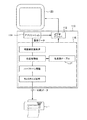
図2は、プリンタドライバが行う基本的な処理の概略的な説明図である。既に説明された構成要素については、同じ符号を付しているので、説明を省略する。
コンピュータ110では、コンピュータに搭載されたオペレーティングシステムの下、ビデオドライバ112やアプリケーションプログラム114やプリンタドライバ116などのコンピュータプログラムが動作している。ビデオドライバ112は、アプリケーションプログラム114やプリンタドライバ116からの表示命令に従って、例えばユーザインターフェース等を表示装置120に表示する機能を有する。アプリケーションプログラム114は、例えば、画像編集などを行う機能を有し、画像に関するデータ(画像データ)を作成する。ユーザは、アプリケーションプログラム114のユーザインターフェースを介して、アプリケーションプログラム114により編集した画像を印刷する指示を与えることができる。アプリケーションプログラム114は、印刷の指示を受けると、プリンタドライバ116に画像データを出力する。
=== Printer driver ===
<About the printer driver>
FIG. 2 is a schematic explanatory diagram of basic processing performed by the printer driver. The components already described are given the same reference numerals, and the description thereof is omitted.
In the
プリンタドライバ116は、アプリケーションプログラム114から画像データを受け取り、この画像データを印刷データに変換し、印刷データをプリンタに出力する。ここで、印刷データとは、プリンタ1が解釈できる形式のデータであって、各種のコマンドデータと画素データとを有するデータである。ここで、コマンドデータとは、プリンタに特定の動作の実行を指示するためのデータである。また、画素データとは、印刷される画像(印刷画像)を構成する画素に関するデータであり、例えば、ある画素に対応する紙上の位置に形成されるドットに関するデータ(ドットの色や大きさ等のデータ)である。
The
プリンタドライバ116は、アプリケーションプログラム114から出力された画像データを印刷データに変換するため、解像度変換処理・色変換処理・ハーフトーン処理・ラスタライズ処理などを行う。以下に、プリンタドライバ116が行う各種の処理について説明する。
The
解像度変換処理は、アプリケーションプログラム114から出力された画像データ(テキストデータ、イメージデータなど)を、紙に印刷する際の解像度に変換する処理である。例えば、紙に画像を印刷する際の解像度が720×720dpiに指定されている場合、アプリケーションプログラム114から受け取った画像データを720×720dpiの解像度の画像データに変換する。なお、解像度変換処理後の画像データは、RGB色空間により表される多階調(例えば256階調)のRGBデータである。以下、画像データを解像度変換処理したRGBデータをRGB画像データと呼ぶ。
The resolution conversion process is a process of converting image data (text data, image data, etc.) output from the
色変換処理は、RGBデータをCMYK色空間により表されるCMYKデータに変換する処理である。なお、CMYKデータは、プリンタが有するインクの色に対応したデータである。この色変換処理は、RGB画像データの階調値とCMYK画像データの階調値とを対応づけたテーブル(色変換ルックアップテーブルLUT)をプリンタドライバ116が参照することによって行われる。この色変換処理により、各画素についてのRGBデータが、インク色に対応するCMYKデータに変換される。なお、色変換処理後のデータは、CMYK色空間により表される256階調のCMYKデータである。以下、RGB画像データを色変換処理したCMYKデータをCMYK画像データと呼ぶ。
The color conversion process is a process for converting RGB data into CMYK data represented by a CMYK color space. The CMYK data is data corresponding to the ink color of the printer. This color conversion processing is performed by the
ハーフトーン処理は、高階調数のデータを、プリンタが形成可能な階調数のデータに変換する処理である。例えば、ハーフトーン処理により、256階調を示すデータが、2階調を示す1ビットデータや4階調を示す2ビットデータに変換される。ハーフトーン処理では、ディザ法・γ補正・誤差拡散法などを利用して、プリンタがドットを分散して形成できるように画素データを作成する。プリンタドライバ116は、ハーフトーン処理を行うとき、ディザ法を行う場合にはディザテーブルを参照し、γ補正を行う場合にはガンマテーブルを参照し、誤差拡散法を行う場合は拡散された誤差を記憶するための誤差メモリを参照する。ハーフトーン処理されたデータは、前述のRGBデータと同等の解像度(例えば720×720dpi)を有している。ハーフトーン処理されたデータは、例えば、各画素につき1ビット又は2ビットのデータから構成される。以下、ハーフトーン処理されたデータのうち、1ビットデータのものを2値データと呼び、2ビットデータのものを多値データと呼ぶ。
The halftone process is a process for converting high gradation number data into gradation number data that can be formed by a printer. For example, data representing 256 gradations is converted into 1-bit data representing 2 gradations or 2-bit data representing 4 gradations by halftone processing. In the halftone process, pixel data is created by using a dither method, γ correction, error diffusion method, or the like so that the printer can form dots dispersedly. When performing halftone processing, the
ラスタライズ処理は、マトリクス状の画像データを、プリンタに転送すべきデータ順に変更する処理である。ラスタライズ処理されたデータは、印刷データに含まれる画素データとして、プリンタに出力される。 The rasterization process is a process of changing matrix image data in the order of data to be transferred to the printer. The rasterized data is output to the printer as pixel data included in the print data.
<プリンタドライバの設定について>
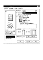
図3は、プリンタドライバのユーザインターフェースの説明図である。このプリンタドライバのユーザインターフェースは、ビデオドライバ112を介して、表示装置に表示される。ユーザーは、入力装置130を用いて、プリンタドライバの各種の設定を行うことができる。
<About printer driver settings>
FIG. 3 is an explanatory diagram of the user interface of the printer driver. The user interface of this printer driver is displayed on the display device via the
ユーザーは、この画面上から、印刷モードを選択することができる。例えば、ユーザーは、印刷モードとして、高速印刷モード又はファイン印刷モードを選択することができる。そして、プリンタドライバは、選択された印刷モードに応じた形式になるように、画像データを印刷データに変換する。
また、ユーザーは、この画面上から、印刷の解像度(印刷するときのドットの間隔)を選択することができる。例えば、ユーザーは、この画面上から、印刷の解像度として720dpiや360dpiを選択することができる。そして、プリンタドライバは、選択された解像度に応じて解像度変換処理を行い、画像データを印刷データに変換する。
また、ユーザーは、この画面上から、印刷に用いられる印刷用紙を選択することができる。例えば、ユーザーは、印刷用紙として、普通紙や光沢紙を選択することができる。紙の種類(紙種)が異なれば、インクの滲み方や乾き方も異なるため、印刷に適したインク量も異なる。そのため、プリンタドライバは、選択された紙種に応じて、画像データを印刷データに変換する。
The user can select a print mode from this screen. For example, the user can select the high-speed print mode or the fine print mode as the print mode. Then, the printer driver converts the image data into print data so as to have a format corresponding to the selected print mode.
Further, the user can select the printing resolution (dot interval when printing) from this screen. For example, the user can select 720 dpi or 360 dpi as the print resolution from this screen. Then, the printer driver performs resolution conversion processing according to the selected resolution, and converts the image data into print data.
Further, the user can select a printing paper used for printing from this screen. For example, the user can select plain paper or glossy paper as the printing paper. If the paper type (paper type) is different, the ink bleeding and drying methods are also different, so the ink amount suitable for printing also differs. Therefore, the printer driver converts the image data into print data according to the selected paper type.
このように、プリンタドライバは、ユーザインターフェースを介して設定された条件に従って、画像データを印刷データに変換する。なお、ユーザーは、この画面上から、プリンタドライバの各種の設定を行うことができるほか、カートリッジ内のインクの残量を知ること等もできる。 As described above, the printer driver converts the image data into print data according to the conditions set via the user interface. The user can make various settings of the printer driver from this screen, and can also know the remaining amount of ink in the cartridge.
===プリンタの構成===
<インクジェットプリンタの構成について>
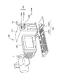
図4は、本実施形態のプリンタの全体構成のブロック図である。また、図5は、本実施形態のプリンタの全体構成の概略図である。また、図6は、本実施形態のプリンタの全体構成の横断面図である。以下、本実施形態のプリンタの基本的な構成について説明する。
=== Configuration of Printer ===
<Inkjet printer configuration>
FIG. 4 is a block diagram of the overall configuration of the printer of this embodiment. FIG. 5 is a schematic diagram of the overall configuration of the printer of this embodiment. FIG. 6 is a cross-sectional view of the overall configuration of the printer of this embodiment. Hereinafter, the basic configuration of the printer of this embodiment will be described.
本実施形態のプリンタは、搬送ユニット20、キャリッジユニット30、ヘッドユニット40、検出器群50、およびコントローラ60を有する。外部装置であるコンピュータ110から印刷データを受信したプリンタ1は、コントローラ60によって各ユニット(搬送ユニット20、キャリッジユニット30、ヘッドユニット40)を制御する。コントローラ60は、コンピュータ110から受信した印刷データに基づいて、各ユニットを制御し、紙に画像を形成する。プリンタ1内の状況は検出器群50によって監視されており、検出器群50は、検出結果をコントローラ60に出力する。検出器群50から検出結果を受けたコントローラ60は、その検出結果に基づいて、各ユニットを制御する。
The printer of this embodiment includes a
搬送ユニット20は、媒体(例えば、紙Sなど)を印刷可能な位置に送り込み、印刷時に所定の方向(以下、搬送方向という)に所定の搬送量で紙を搬送させるためのものである。すなわち、搬送ユニット20は、紙を搬送する搬送機構(搬送手段)として機能する。搬送ユニット20は、給紙ローラ21と、搬送モータ22(PFモータとも言う)と、搬送ローラ23と、プラテン24と、排紙ローラ25とを有する。ただし、搬送ユニット20が搬送機構として機能するためには、必ずしもこれらの構成要素を全て必要とするわけではない。給紙ローラ21は、紙挿入口に挿入された紙をプリンタ内に自動的に給紙するためのローラである。給紙ローラ21は、D形の断面形状をしており、円周部分の長さは搬送ローラ23までの搬送距離よりも長く設定されているので、この円周部分を用いて紙を搬送ローラ23まで搬送できる。搬送モータ22は、紙を搬送方向に搬送するためのモータであり、DCモータにより構成される。搬送ローラ23は、給紙ローラ21によって給紙された紙Sを印刷可能な領域まで搬送するローラであり、搬送モータ22によって駆動される。プラテン24は、印刷中の紙Sを支持する。排紙ローラ25は、印刷が終了した紙Sをプリンタの外部に排出するローラである。この排紙ローラ25は、搬送ローラ23と同期して回転する。
The
キャリッジユニット30は、ヘッドを所定の方向(以下、移動方向という)に移動(走査とも呼ばれる)させるためのものである。キャリッジユニット30は、キャリッジ31と、キャリッジモータ32(CRモータとも言う)とを有する。キャリッジ31は、移動方向に往復移動可能である。(これにより、ヘッドが移動方向に沿って移動する。)また、キャリッジ31は、インクを収容するインクカートリッジを着脱可能に保持している。キャリッジモータ32は、キャリッジ31を移動方向に移動させるためのモータであり、DCモータにより構成される。
The
ヘッドユニット40は、紙にインクを吐出するためのものである。ヘッドユニット40は、ヘッド41を有する。ヘッド41は、インク吐出部であるノズルを複数有し、各ノズルから断続的にインクを吐出する。このヘッド41は、キャリッジ31に設けられている。そのため、キャリッジ31が移動方向に移動すると、ヘッド41も移動方向に移動する。そして、ヘッド41が移動方向に移動中にインクを断続的に吐出することによって、移動方向に沿ったドットライン(ラスタライン)が紙に形成される。
The
検出器群50には、リニア式エンコーダ51、ロータリー式エンコーダ52、紙検出センサ53、および光学センサ54等が含まれる。リニア式エンコーダ51は、キャリッジ31の移動方向の位置を検出するためのものである。ロータリー式エンコーダ52は、搬送ローラ23の回転量を検出するためのものである。紙検出センサ53は、印刷される紙の先端の位置を検出するためのものである。この紙検出センサ53は、給紙ローラ21が搬送ローラ23に向かって紙を給紙する途中で、紙の先端の位置を検出できる位置に設けられている。なお、紙検出センサ53は、機械的な機構によって紙の先端を検出するメカニカルセンサである。詳しく言うと、紙検出センサ53は搬送方向に回転可能なレバーを有し、このレバーは紙の搬送経路内に突出するように配置されている。そのため、紙の先端がレバーに接触し、レバーが回転させられるので、紙検出センサ53は、このレバーの動きを検出することによって、紙の先端の位置を検出する。光学センサ54は、キャリッジ31に取付けられている。光学センサ54は、発光部から紙に照射された光の反射光を受光部が検出することにより、紙の有無を検出する。そして、光学センサ54は、キャリッジ41によって移動しながら紙の端部の位置を検出する。光学センサ54は、光学的に紙の端部を検出するため、機械的な紙検出センサ53よりも、検出精度が高い。
The
コントローラ60は、プリンタの制御を行うための制御ユニット(制御手段)である。コントローラ60は、インターフェース部61と、CPU62と、メモリ63と、ユニット制御回路64とを有する。インターフェース部61は、外部装置であるコンピュータ110とプリンタ1との間でデータの送受信を行うためのものである。CPU62は、プリンタ全体の制御を行うための演算処理装置である。メモリ63は、CPU62のプログラムを格納する領域や作業領域等を確保するためのものであり、RAM、EEPROM等の記憶手段を有する。CPU62は、メモリ63に格納されているプログラムに従って、ユニット制御回路64を介して各ユニットを制御する。
The
<印刷動作について>
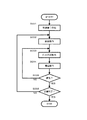
図7は、印刷時の処理のフロー図である。以下に説明される各処理は、コントローラ60が、メモリ63内に格納されたプログラムに従って、各ユニットを制御することにより実行される。このプログラムは、各処理を実行するためのコードを有する。
<About printing operation>
FIG. 7 is a flowchart of processing during printing. Each process described below is executed by the
コントローラ60は、コンピュータ110からインターフェース部61を介して、印刷命令を受信する(S001)。この印刷命令は、コンピュータ110から送信される印刷データのヘッダに含まれている。そして、コントローラ60は、受信した印刷データに含まれる各種コマンドの内容を解析し、各ユニットを用いて、以下の給紙処理・搬送処理・インク吐出処理等を行う。
The
まず、コントローラ60は、給紙処理を行う(S002)。給紙処理とは、印刷すべき紙をプリンタ内に供給し、印刷開始位置(頭出し位置とも言う)に紙を位置決めする処理である。コントローラ60は、給紙ローラ21を回転させ、印刷すべき紙を搬送ローラ23まで送る。コントローラ60は、搬送ローラ23を回転させ、給紙ローラ21から送られてきた紙を印刷開始位置に位置決めする。紙が印刷開始位置に位置決めされたとき、ヘッド41の少なくとも一部のノズルは、紙と対向している。
First, the
次に、コントローラ60は、ドット形成動作を行う(S003)。ドット形成動作とは、移動方向に沿って移動するヘッドからインクを断続的に吐出させ、紙上にドットを形成する処理である。コントローラ60は、キャリッジモータ32を駆動し、キャリッジ31を移動方向に移動させる。そして、コントローラ60は、キャリッジ31が移動している間に、印刷データに基づいてヘッドからインクを吐出させる。ヘッドから吐出されたインク滴が紙上に着弾すれば、紙上にドットが形成される。
Next, the
次に、コントローラ60は、搬送処理を行う(S004)。搬送処理とは、紙をヘッドに対して搬送方向に沿って相対的に移動させる処理である。コントローラ60は、搬送モータを駆動し、搬送ローラを回転させて紙を搬送方向に搬送する。この搬送処理により、ヘッド41は、先ほどのドット形成動作によって形成されたドットの位置とは異なる位置に、ドットを形成することが可能になる。
Next, the
次に、コントローラ60は、印刷中の紙の排紙の判断を行う(S005)。印刷中の紙に印刷するためのデータが残っていれば、排紙は行われない。そして、コントローラ60は、印刷するためのデータがなくなるまでドット形成動作と搬送処理とを交互に繰り返し、ドットから構成される画像を徐々に紙に印刷する。印刷中の紙に印刷するためのデータがなくなれば、コントローラ60は、その紙を排紙する。コントローラ60は、排紙ローラを回転させることにより、印刷した紙を外部に排出する。なお、排紙を行うか否かの判断は、印刷データに含まれる排紙コマンドに基づいても良い。
Next, the
次に、コントローラ60は、印刷を続行するか否かの判断を行う(S006)。次の紙に印刷を行うのであれば、印刷を続行し、次の紙の給紙処理を開始する。次の紙に印刷を行わないのであれば、印刷動作を終了する。
Next, the
<ノズルについて>
図8は、ヘッド41の下面におけるノズルの配列を示す説明図である。ヘッド41の下面には、ブラックインクノズル群Kと、シアンインクノズル群Cと、マゼンタインクノズル群Mと、イエローインクノズル群Yが形成されている。各ノズル群は、各色のインクを吐出するための吐出口であるノズルを複数個(本実施形態では180個)備えている。
<About nozzle>
FIG. 8 is an explanatory diagram showing the arrangement of nozzles on the lower surface of the
各ノズル群の複数のノズルは、搬送方向に沿って、一定の間隔(ノズルピッチ:k・D)でそれぞれ整列している。ここで、Dは、搬送方向における最小のドットピッチ(つまり、紙Sに形成されるドットの最高解像度での間隔)である。また、kは、1以上の整数である。例えば、ノズルピッチが180dpi(1/180インチ)であって、搬送方向のドットピッチが720dpi(1/720インチ)である場合、k=4である。また、同じノズルピッチでも、搬送方向のドットピッチが1440dpi(1/1440インチ)である場合、k=8になる。以下の説明では、特に説明のない限り、ノズルピッチを180dpiとし、ドットピッチを720dpiとする。 The plurality of nozzles of each nozzle group are aligned at a constant interval (nozzle pitch: k · D) along the transport direction. Here, D is the minimum dot pitch in the carrying direction (that is, the interval at the highest resolution of dots formed on the paper S). K is an integer of 1 or more. For example, when the nozzle pitch is 180 dpi (1/180 inch) and the dot pitch in the transport direction is 720 dpi (1/720 inch), k = 4. Further, even if the nozzle pitch is the same, if the dot pitch in the transport direction is 1440 dpi (1/1440 inch), k = 8. In the following description, the nozzle pitch is 180 dpi and the dot pitch is 720 dpi unless otherwise specified.
各ノズル群のノズルは、下流側のノズルほど若い番号が付されている(♯1〜♯180)。つまり、ノズル♯1は、ノズル♯180よりも搬送方向の下流側に位置している。各ノズルには、各ノズルを駆動してインク滴を吐出させるための駆動素子としてピエゾ素子(不図示)が設けられている。また、光学センサ54は、紙搬送方向の位置に関して、一番上流側にあるノズル♯180とほぼ同じ位置にある。
The nozzles in each nozzle group are assigned a lower number in the downstream nozzle (# 1 to # 180). That is, the
===印刷方式===
プリンタドライバは、ユーザーがインターフェース上で設定した内容に応じて、インターレース印刷やオーバーラップ印刷のための印刷データを生成する。
=== Printing method ===
The printer driver generates print data for interlaced printing or overlap printing according to the contents set by the user on the interface.
<インターレース方式について1>
まず、インターレース方式による印刷方式ついて、説明する。ここで、『インターレース方式』とは、1回のパスで記録されるラスタラインの間に記録されないラスタラインが挟まれるような印刷方式を意味する。また、『パス』とは、ノズルが移動方向に1回移動する動作(ドット形成動作)をいう。『ラスタライン』とは、移動方向に並ぶ画素の列であり、走査ラインともいう。また、『画素』とは、インク滴を着弾させドットを記録する位置を規定するために、被印刷体上に仮想的に定められた方眼状の桝目である。
<
First, an interlaced printing method will be described. Here, the “interlace method” means a printing method in which raster lines that are not recorded are sandwiched between raster lines that are recorded in one pass. The “pass” refers to an operation (dot formation operation) in which the nozzle moves once in the movement direction. A “raster line” is a row of pixels lined up in the movement direction, and is also called a scanning line. Further, the “pixel” is a square grid which is virtually defined on the printing medium in order to define the position where the ink droplet is landed and the dot is recorded.
図9A及び図9Bは、インターレース方式の説明図である。なお、説明の便宜上、ヘッド(又はノズル群)が紙に対して移動しているように描かれているが、同図はヘッドと紙との相対的な位置を示すものであって、実際には紙が搬送方向に移動されている。また、本来、搬送方向に並ぶノズル数は180個であるが、説明を簡単にするため、ここではノズル数を8個とする。また、ヘッドは複数のノズル群を有しているが、説明を簡単にするため、ここではヘッドの1つのノズル群について説明を行う。 9A and 9B are explanatory diagrams of the interlace method. For convenience of explanation, the head (or nozzle group) is depicted as moving with respect to the paper, but this figure shows the relative position of the head and the paper. The paper is moved in the transport direction. In addition, the number of nozzles arranged in the transport direction is originally 180, but here the number of nozzles is set to 8 for simplicity of explanation. Further, although the head has a plurality of nozzle groups, in order to simplify the description, one nozzle group of the head will be described here.
同図において、黒丸で示されたノズルはインクを吐出可能なノズルであり、白丸で示されたノズルはインクを吐出不可なノズルである。図9Aは、パス1〜パス4におけるヘッドの位置とドットの形成の様子を示し、図9Bは、パス1〜パス6におけるヘッドの位置とドットの形成の様子を示している。
In the figure, nozzles indicated by black circles are nozzles that can eject ink, and nozzles indicated by white circles are nozzles that cannot eject ink. FIG. 9A shows the head position and dot formation in
インターレース方式では、紙が搬送方向に一定の搬送量Fで搬送される毎に、各ノズルが、その直前のパスで記録されたラスタラインのすぐ上のラスタラインを記録する。このように搬送量を一定にして記録を行うためには、インクを吐出可能なノズル数N(整数)はkと互いに素の関係にあり、搬送量FはN・Dに設定される。 In the interlace method, each time the paper is transported at a constant transport amount F in the transport direction, each nozzle records a raster line immediately above the raster line recorded in the immediately preceding pass. In order to perform recording with a constant carry amount in this way, the number N (integer) of nozzles that can eject ink is relatively prime to k, and the carry amount F is set to N · D.
同図では、ヘッドは搬送方向に沿って配列された8つのノズルを有する。しかし、ノズルピッチkは4なので、インターレース方式を行うための条件である「Nとkが互いに素の関係」を満たすために、全てのノズルを用いることはできない。そこで、8つのノズルのうち、7つのノズルを用いてインターレース方式が行われる。また、7つのノズルが用いられるため、紙は搬送量7・Dにて搬送される。その結果、例えば、180dpi(4・D)のノズルピッチのノズル群を用いて、720dpi(=D)のドット間隔にて紙にドットが形成される。 In the figure, the head has eight nozzles arranged along the transport direction. However, since the nozzle pitch k is 4, not all nozzles can be used in order to satisfy the condition for performing the interlace method, “N and k are relatively prime”. Therefore, the interlace method is performed using seven of the eight nozzles. Further, since seven nozzles are used, the paper is transported with a transport amount of 7 · D. As a result, for example, using a nozzle group having a nozzle pitch of 180 dpi (4 · D), dots are formed on the paper at a dot interval of 720 dpi (= D).
同図は、最初のラスタラインはパス3のノズル♯3が形成し、2番目のラスタラインはパス2のノズル♯5が形成し、3番目のラスタラインはパス1のノズル♯7が形成し、4番目のラスタラインはパス4のノズル♯2が形成し、連続的なラスタラインが形成される様子を示している。なお、パス3以降では、7つのノズル(♯2〜♯8)がインクを吐出し、紙が一定の搬送量F(=7・D)にて搬送されて、連続的なラスタラインがドット間隔Dにて形成される。
In the drawing, the first raster line is formed by
<インターレース方式について2>
上記の説明では、説明を簡単にするため、ノズルの数は8個であった。しかし、実際のノズル数は、180個である。この場合のインターレース方式について、説明する。
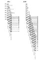
図10Aは、実際のインターレース方式の説明図である。同図では、ヘッドと紙との相対的な位置を示している。ここでは、ヘッドは搬送方向に沿って配列された180個のノズルを有する。しかし、ノズルピッチkは4なので、インターレース方式を行うための条件である「Nとkが互いに素の関係」を満たすために、全てのノズルを用いることはできない。そこで、180個のノズルのうち、179個のノズルを用いてインターレース方式が行われる。また、179個のノズルが用いられるため、紙は搬送量179・Dにて搬送される。
<About the
In the above description, the number of nozzles is eight in order to simplify the description. However, the actual number of nozzles is 180. The interlace method in this case will be described.
FIG. 10A is an explanatory diagram of an actual interlace method. In the figure, the relative positions of the head and the paper are shown. Here, the head has 180 nozzles arranged in the transport direction. However, since the nozzle pitch k is 4, not all nozzles can be used in order to satisfy the condition for performing the interlace method, “N and k are relatively prime”. Therefore, the interlace method is performed using 179 nozzles out of 180 nozzles. In addition, since 179 nozzles are used, the paper is carried by a carry amount of 179 · D.
あるパスにおいて、ヘッド41Aは、移動方向に移動しながらインクを吐出して、紙の領域1にドット(ラスタライン)を形成する。次に、紙が179・D(=179/720インチ)にて搬送され、紙に対してヘッドが図中のヘッド41Bの位置に相対的に移動する。次のパスにおいて、ヘッド41Bは、移動方向に移動しながらインクを吐出して、紙の領域1及び領域2にドット(ラスタライン)を形成する。ここでは、このような動作を、ヘッド41Eが紙にドットを形成するまで続けるものとする。
In a certain pass, the
図10Bは、ヘッド41Eが紙にドットを形成した後の各領域のドット形成状況の説明図である。同図において、白丸は、ドットが形成されていない画素を示している。また、黒丸は、ドットが形成された画素を示している。
FIG. 10B is an explanatory diagram of the dot formation status in each region after the
領域1では、ヘッド41A〜ヘッド41Dによって、4回のパスによってドット(ラスタライン)が形成されている。また、領域2では、ヘッド41B〜ヘッド41Eによって、4回のパスによってドットが形成されている。このように、4回のパスを経過した領域では、その領域内の全ての画素に、ドットが形成されている。領域3では、ヘッド41C〜41Eによって、3回のパスによってドットが形成されている。このように、3回のパスを経過した領域では、4つのラスタラインのうちの3つのラスタラインの画素に、ドットが形成されている。領域4では、ヘッド41D及び41Eによって、2回のパスによってドットが形成されている。このように、2回のパスを経過した領域では、4つのラスタラインのうちの2つのラスタラインの画素に、ドットが形成されている。領域5では、41Eによって、1回のパスによってドットが形成されている。このように、1回のパスを経過した領域では、4つのラスタラインのうちの1つのラスタラインの画素に、ドットが形成されている。なお、領域6では、まだドットが形成されていない状態である。
In the
このように、インターレース方式では、ヘッドが1度移動しただけでは(1回のパスだけでは)、そのヘッドに対向する領域の全ての画素にドットが形成されるというわけではない。具体的には、ある領域の全ての画素にドットが形成されるには、k回のパスを経過する必要がある。 As described above, in the interlace method, just by moving the head once (by only one pass), dots are not formed in all the pixels in the area facing the head. Specifically, it is necessary to pass k passes in order for dots to be formed in all pixels in a certain region.
<オーバーラップ方式について1>
図11A及び図11Bは、ノズルの数が8個の場合のオーバーラップ方式の説明図である。前述のインターレース方式では、一つのラスタラインは一つのノズルにより形成されていた。一方、オーバーラップ方式では、例えば、一つのラスタラインが、二つ以上のノズルにより形成されている。
<About the
FIG. 11A and FIG. 11B are explanatory diagrams of the overlap method when the number of nozzles is eight. In the interlace method described above, one raster line is formed by one nozzle. On the other hand, in the overlap method, for example, one raster line is formed by two or more nozzles.
オーバーラップ方式では、紙が搬送方向に一定の搬送量Fで搬送される毎に、各ノズルが、数ドットおきに間欠的にドットを形成する。そして、他のパスにおいて、他のノズルが既に形成されている間欠的なドットを補完するようにドットを形成することにより、1つラスタラインが複数のノズルにより完成する。このようにM回のパスにて1つのラスタラインが完成する場合、オーバーラップ数Mと定義する。同図では、各ノズルは、1ドットおきに間欠的にドットが形成されるので、パス毎に奇数番目の画素又は偶数番目の画素にドットが形成される。そして、1つのラスタラインが2つのノズルにより形成されているので、オーバーラップ数M=2になる。なお、前述のインターレース方式の場合、オーバーラップ数M=1になる。 In the overlap method, each time the paper is transported at a constant transport amount F in the transport direction, each nozzle intermittently forms a dot every several dots. Then, in another pass, dots are formed so as to complement intermittent dots already formed by other nozzles, thereby completing one raster line with a plurality of nozzles. When one raster line is completed in M passes in this way, it is defined as the overlap number M. In the figure, since each nozzle intermittently forms dots every other dot, dots are formed in odd-numbered pixels or even-numbered pixels for each pass. Since one raster line is formed by two nozzles, the overlap number M = 2. In the case of the above-described interlace method, the overlap number M = 1.
オーバーラップ方式において、搬送量を一定にして記録を行うためには、(1)N/Mが整数であること、(2)N/Mはkと互いに素の関係にあること、(3)搬送量Fが(N/M)・Dに設定されること、が条件となる。 In the overlap method, in order to perform recording with a constant conveyance amount, (1) N / M is an integer, (2) N / M is relatively prime to k, (3) The condition is that the carry amount F is set to (N / M) · D.
同図では、ノズル群は搬送方向に沿って配列された8つのノズルを有する。しかし、ノズル群のノズルピッチkは4なので、オーバーラップ方式を行うための条件である「N/Mとkが互いに素の関係」を満たすために、全てのノズルを用いることはできない。そこで、8つのノズルのうち、6つのノズルを用いてオーバーラップ方式が行われる。また、6つのノズルが用いられるため、紙は搬送量3・Dにて搬送される。
その結果、例えば、180dpi(4・D)のノズルピッチのノズル群を用いて、720dpi(=D)のドット間隔にて紙にドットが形成される。また、1つのパスにおいて、各ノズルは移動方向に1ドットおきに間欠的にドットを形成する。図中において、移動方向に2つのドットが描かれているラスタラインは既に完成されている。例えば、図11Aにおいて、最初のラスタラインから6番目のラスタラインまでは、既に完成されている。1つのドットが描かれているラスタラインは、1ドットおきに間欠的にドットが形成されているラスタラインである。例えば、7番目や10番目のラスタラインは、1ドットおきに間欠的にドットが形成されている。なお、1ドットおきに間欠的にドットが形成された7番目のラスタラインは、パス9のノズル♯1が補完するようにドットを形成することによって、完成される。
なお、パス7以降では、6つのノズル(♯3〜♯8)がインクを吐出し、紙が一定の搬送量F(=3・D)にて搬送されて、連続的なラスタラインがドット間隔Dにて形成される。
In the figure, the nozzle group has eight nozzles arranged along the transport direction. However, since the nozzle pitch k of the nozzle group is 4, not all nozzles can be used in order to satisfy “N / M and k are relatively prime”, which is a condition for performing the overlap method. Therefore, the overlap method is performed using six of the eight nozzles. Further, since six nozzles are used, the paper is transported with a transport amount of 3 · D.
As a result, for example, using a nozzle group having a nozzle pitch of 180 dpi (4 · D), dots are formed on the paper at a dot interval of 720 dpi (= D). Further, in one pass, each nozzle intermittently forms dots every other dot in the movement direction. In the figure, the raster line in which two dots are drawn in the moving direction has already been completed. For example, in FIG. 11A, the first raster line to the sixth raster line have already been completed. A raster line in which one dot is drawn is a raster line in which dots are intermittently formed every other dot. For example, in the seventh and tenth raster lines, dots are intermittently formed every other dot. The seventh raster line in which dots are intermittently formed every other dot is completed by forming dots so that
In
図12Aは、ノズルの数が180個の場合のオーバーラップ方式の説明図である。ノズルの数が180個の場合、178個のノズルが用いられ、紙は一定の搬送量89・Dにて搬送される。
図12Bは、各領域のドット形成状況の説明図である。
FIG. 12A is an explanatory diagram of an overlap method when the number of nozzles is 180. When the number of nozzles is 180, 178 nozzles are used, and the paper is transported at a
FIG. 12B is an explanatory diagram of the dot formation status in each region.
領域1では、ヘッド41A〜ヘッド41Hによって、8回のパスによってドットが形成されている。また、領域2では、ヘッド41B〜ドット41Iによって、8回のパスによってドットが形成されている。このように、8回のパスを経過した領域では、その領域内の全ての画素に、ドットが形成されている。領域3では、ヘッド41C〜ヘッド41Iによって、7回のパスによってドットが形成されている。このように、7回のパスを経過した領域では、4つのラスタラインのうちの3つのラスタラインが完成し、残りの1つのラスタラインには1ドットおきにドットが形成されている。このように、ヘッドは、各領域において、1回のパス毎に、4つのラスタラインのうちの1つのラスタラインに、1ドットおきにドットを形成する。また、4回のパスを終えた領域では、千鳥格子状にドットが形成される。
In the
オーバーラップ方式でも、ヘッドが1度移動しただけでは(1回のパスだけでは)、そのヘッドに対向する領域の全ての画素にドットが形成されるというわけではない。具体的には、ある領域の全ての画素にドットが形成されるには、8回(k×M回)のパスを経過する必要がある。なお、オーバーラップ方式も、1回のパスで記録されるラスタラインの間に記録されないラスタラインが挟まれているので、インターレース方式の概念に含まれる印刷方式である。 Even in the overlap mode, if the head is moved once (only with one pass), dots are not formed on all the pixels in the area facing the head. Specifically, in order to form dots at all the pixels in a certain region, it is necessary to pass eight (k × M) passes. Note that the overlap method is a printing method included in the concept of the interlace method because raster lines that are not recorded are sandwiched between raster lines that are recorded in one pass.
===縁なし印刷===
「縁なし印刷」とは、紙の全面に印刷を行う印刷である。「縁なし印刷」を行えば、余白を作らずに、紙の全面に画像を印刷できる。ここでは、「縁なし印刷」の印刷方法について説明する。なお、「縁なし印刷」を行うか否かは、ユーザーがインターフェース上で設定した内容に基づいて、プリンタドライバにより判断される。
=== Borderless printing ===
“Borderless printing” is printing in which printing is performed on the entire surface of paper. By performing “borderless printing”, an image can be printed on the entire surface of the paper without creating a margin. Here, a printing method of “marginless printing” will be described. Whether or not “marginless printing” is to be performed is determined by the printer driver based on the contents set by the user on the interface.
図13は、縁なし印刷のときのインク吐出領域の説明図である。同図において、内側の太線の四角形は、紙の領域(紙の大きさ)を示している。同図において、外側の太線の四角形は、インク吐出領域を示している(但し、同図は紙に対する相対的なインク吐出領域を示している)。 FIG. 13 is an explanatory diagram of an ink discharge area at the time of borderless printing. In the figure, a thick rectangle on the inner side indicates a paper area (paper size). In the same figure, the thick bold rectangle on the outer side shows the ink ejection area (however, this figure shows the ink ejection area relative to the paper).
このように、縁なし印刷では、プリンタは、紙よりも広い領域にインクを吐出して、紙の全面に印刷を行っている。これにより、紙が斜めに搬送されたりしても、紙の全面に画像が印刷される。
但し、紙よりも広い領域にインクを吐出しているため、同図の斜線部に吐出されたインクは、紙に着弾せずに、プラテン24に着弾する。しかし、プラテン24の紙を支持する部分にインクが着弾すると、紙の裏面をインクで汚してしまう。
そこで、本実施形態では、プラテン24は溝を有している。この溝は、プラテンの紙を支持する部分よりも凹んだ形状になっている。そして、紙に着弾しないインクは、この溝に着弾するようにしている。
As described above, in borderless printing, the printer prints on the entire surface of the paper by ejecting ink over a wider area than the paper. As a result, even if the paper is transported obliquely, an image is printed on the entire surface of the paper.
However, since the ink is ejected to a wider area than the paper, the ink ejected to the shaded area in the figure does not land on the paper but land on the
Therefore, in the present embodiment, the
図14A〜図14Cは、縁なし印刷するときのインクの吐出の説明図である。同図において、紙Sは、図中の右から左に向かって搬送される。ヘッド41は、紙面に垂直な方向に往復しながらインクを吐出する。プラテン24は、縁なし印刷を行うための溝241を有している。
14A to 14C are explanatory diagrams of ink ejection when borderless printing is performed. In the figure, the paper S is conveyed from right to left in the figure. The
図14Aは、紙の上端部分を縁なし印刷するときの説明図である。このとき、仮に全部のノズルからインクを吐出すると、プラテン24の紙を支持する部分にインクが着弾し、紙の裏面を汚してしまう。そこで、溝241に対向するノズルのみからインクを吐出して、紙に画像を形成する。これにより、紙に着弾しないインクは、溝241に着弾する。以下、このような印刷を「上端印刷」と呼ぶ。
FIG. 14A is an explanatory diagram when borderless printing is performed on the upper end portion of the paper. At this time, if ink is ejected from all the nozzles, the ink lands on the portion of the
図14Bは、紙の中央部分を印刷するときの説明図である。このとき、全てのノズルからインクを吐出しても、紙にインクが着弾し、プラテン24にインクが着弾することはない。そこで、全てのノズルからインクを吐出して、紙に画像を形成する。以下、このような印刷を「通常印刷」と呼ぶ。
FIG. 14B is an explanatory diagram when printing the central portion of the paper. At this time, even if ink is ejected from all the nozzles, the ink lands on the paper and the ink does not land on the
図14Cは、紙の下端部分を縁なし印刷するときの説明図である。このとき、仮に全部のノズルからインクを吐出すると、プラテン24の紙を支持する部分にインクが着弾し、紙の裏面を汚してしまう。そこで、溝241に対向するノズルのみからインクを吐出して、紙に画像を形成する。これにより、紙に着弾しないインクは、溝241に着弾する。以下、このような印刷を「下端印刷」と呼ぶ。
FIG. 14C is an explanatory diagram when borderless printing is performed on the lower end portion of the paper. At this time, if ink is ejected from all the nozzles, the ink lands on the portion of the
上端印刷(図14A)と通常印刷(図14B)とを比較すると、インクを吐出可能なノズルの数が異なる。通常印刷では全てのノズルからインクを吐出できるのに対し、上端印刷では、溝241に対向するノズルのみからインクを吐出できないからである。
一方、インターレース方式やオーバーラップ方式では、搬送量Fは、使用可能なノズル数で決定される。使用可能なノズル数をNとすると、搬送量Fは、(N/M)・Dである(インターレース方式ではM=1であり、1ラスタラインを2個のノズルで印刷するオーバーラップ方式ではM=2である)。
このため、上端印刷時の紙の搬送量と、通常印刷時の紙の搬送量は、異なっている。同様の理由により、下端印刷時の紙の搬送量と、通常印刷時の紙の搬送量も、異なっている。
Comparing upper end printing (FIG. 14A) and normal printing (FIG. 14B), the number of nozzles that can eject ink is different. This is because ink can be ejected from all nozzles in normal printing, whereas ink cannot be ejected from only nozzles facing the
On the other hand, in the interlace method and the overlap method, the carry amount F is determined by the number of usable nozzles. When the number of usable nozzles is N, the carry amount F is (N / M) · D (M = 1 in the interlace method, and M in the overlap method in which one raster line is printed by two nozzles. = 2).
For this reason, the transport amount of the paper at the upper end printing and the transport amount of the paper at the normal printing are different. For the same reason, the transport amount of paper at the lower end printing and the transport amount of paper during normal printing are also different.
1枚の紙に縁なし印刷を行うとき、紙には、上端印刷により画像が印刷される領域と、通常印刷により画像が印刷される領域と、下端印刷により画像が印刷される領域と、が存在する。つまり、印刷画像は、上端印刷による印刷画像と、通常印刷による印刷画像と、下端印刷による印刷画像と、を継ぎ合わせて印刷される。しかし、上端印刷・通常印刷・下端印刷のそれぞれの印刷品質が異なると、領域による画質の差が目立ち、印刷画像全体の画質が悪くなる。このような画質の劣化を防ぐためには、搬送量の異なる上端印刷・通常印刷・下端印刷のそれぞれの印刷による印刷画像の画質を、同質に近づけることが重要である。
以下、上端印刷(又は下端印刷)による印刷画像の画質を、どのようにして通常印刷による印刷画像の画質に近づけているかを説明する。
When performing borderless printing on a piece of paper, the paper has an area where an image is printed by upper end printing, an area where an image is printed by normal printing, and an area where an image is printed by lower end printing. Exists. That is, the print image is printed by joining the print image by the upper end printing, the print image by the normal printing, and the print image by the lower end printing. However, if the print qualities of the upper-end printing, normal printing, and lower-end printing are different, the difference in image quality among the areas is conspicuous, and the image quality of the entire printed image is deteriorated. In order to prevent such deterioration in image quality, it is important to make the image quality of the printed images obtained by the printing of the upper end printing, the normal printing, and the lower end printing with different transport amounts close to the same quality.
Hereinafter, it will be described how the image quality of a print image obtained by upper-end printing (or lower-end print) is brought close to the image quality of a print image obtained by normal printing.
===本実施形態のラスタラインの形成順序===
プリンタドライバは、以下に説明するようなラスタラインの形成順序になるように、印刷データを作成する。なお、以下の説明では、ノズル数は全部で180個であり、溝241に対向するノズルの数は30個とする。また、ノズル♯75〜ノズル♯104が、溝241に対向しているものとする。
=== Raster Line Formation Order of this Embodiment ===
The printer driver creates print data so that the raster lines are formed in the order described below. In the following description, the total number of nozzles is 180, and the number of nozzles facing the
<インターレース方式について1>
図15A〜図15Cは、インターレース方式によるドットの形成順序の説明図である。
<
15A to 15C are explanatory diagrams of the dot formation order by the interlace method.
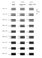
(通常印刷時)
図15Aは、通常印刷時のドットの形成順序の説明図である。なお、インターレース方式の通常印刷については、図10A及び図10Bを用いて既に説明されている。すなわち、インターレース方式の通常印刷では、180個のノズルのうちの179個のノズル(ノズル♯1〜ノズル♯179)が用いられ、搬送量Fは、179・D(=179/720インチ)である。
(Normal printing)
FIG. 15A is an explanatory diagram of the dot formation order during normal printing. Note that interlaced normal printing has already been described with reference to FIGS. 10A and 10B. That is, in the interlaced normal printing, 179 nozzles (
ここでは、図10Aの領域2に焦点をあてて、ドットの形成順序を説明する。
1回目のパス(ドット形成動作)の前は、図15Aの「1回目のパス前」に示されるように、ドットが形成されていない。領域2では、ヘッド41Bのパスが行われるまで、ドットが形成されない。ヘッド41Bが移動方向に移動してインクを吐出することによって、領域2における1回目のパス(ドット形成動作)が行われる。
Here, the dot formation order will be described focusing on the
Before the first pass (dot formation operation), as shown in “Before the first pass” in FIG. 15A, no dots are formed. In the
1回目のパス後、図15Aの「1回目のパス後」に示されるように、領域2には、ラスタラインがノズルピッチずつ離れて形成されている。言い方を変えれば、領域2では、4つのラスタラインのうちの1つのラスタラインが印刷されている。図中の矢印は、領域2において1回目に形成されたラスタラインの位置を示している。また、図中には、領域2のうち、ノズル♯179(インクを吐出可能な搬送方向最上流ノズル)及びノズル♯178により形成されたラスタラインで挟まれる領域が、示されている。
After the first pass, as shown in “After the first pass” in FIG. 15A, raster lines are formed in the
次に、搬送ユニットが179・Dの搬送量にて紙を搬送方向に搬送する。これにより、領域2は、ヘッド41に対して、相対的に下流側に移動する。このときのヘッド41の相対的な位置は、図10Aのヘッド41Cに示される位置である。180個のノズルはノズルピッチ4・Dで配置されているため、搬送ユニットが179・Dで紙を搬送した後、1回目のパスで形成されたラスタラインの「下流側」の位置に、ヘッド41のノズルが位置することになる。例えば、搬送後、ノズル♯134は、ノズル♯179が形成したラスタラインの「下流側」に位置している。
Next, the transport unit transports the paper in the transport direction with a transport amount of 179 · D. As a result, the
そのため、領域2における2回目のパスでは、図15Aの「2回目のパス後」に示されるように、既に形成されているラスタラインの「下流側」に隣接して、ラスタラインが形成される。例えば、ノズル♯134は、ノズル♯179が形成したラスタラインの「下流側」に隣接して、ラスタラインを形成する。(不図示ではあるが、ノズル♯133は、ノズル♯178が形成したラスタラインの「下流側」に隣接して、ラスタラインを形成している。)
3回目のパス以降も同様に、搬送ユニットが179・Dの搬送量にて紙を搬送するため、前回のパスで形成されたラスタラインの「下流側」に隣接して、ラスタラインが形成される。
Therefore, in the second pass in the
Similarly, after the third pass, since the transport unit transports the paper with a transport amount of 179 · D, a raster line is formed adjacent to the “downstream side” of the raster line formed in the previous pass. The
[比較例1]
図15Bは、比較例1の上端印刷時のドットの形成順序の説明図である。同図は、紙の上端付近に位置する領域のドットの形成順序を示している。説明のため図15Aと図15Bが紙面の左右方向に並んで描かれているが、実際には、図15Aに示される領域は、図15Bに示される領域(紙の上端付近に位置する領域)よりも、搬送方向上流側に位置する。
[Comparative Example 1]
FIG. 15B is an explanatory diagram of the dot formation order during upper end printing in Comparative Example 1. This figure shows the dot formation order in the region located near the top edge of the paper. 15A and 15B are drawn side by side in the left-right direction on the paper surface for explanation, but in reality, the region shown in FIG. 15A is the region shown in FIG. 15B (the region located near the top edge of the paper). Rather than the upstream side in the transport direction.
上記の通り、溝241に対向するノズルの数は30個(ノズル♯75〜ノズル♯104)である。上端印刷では、溝に対向するノズルからしかインクを吐出できないので、この30個のノズルしか使用できない。一方、上端印刷でインターレース方式を行うためには、インターレース方式の条件である「Nとk(=4)が互いに素の関係」を満たす必要がある。そこで、比較例1では、この条件を満たす最多の29個のノズル(ノズル♯75〜ノズル♯103)を使用する。
As described above, the number of nozzles facing the
インクを吐出可能なノズル数が29個の場合、搬送ユニットによる紙の搬送量は、29・Dになる。29個のノズルはノズルピッチ4・Dで配置されているため、搬送ユニットが29・Dで紙を搬送した後、1回目のパスで形成されたラスタラインの「上流側」の位置に、ヘッド41のノズルが位置することになる。例えば、搬送後、ノズル♯95は、ノズル♯102が形成したラスタラインの「上流側」に位置している。
When the number of nozzles that can eject ink is 29, the amount of paper transported by the transport unit is 29 · D. Since the 29 nozzles are arranged at a nozzle pitch of 4 · D, after the transport unit transports the paper at 29 · D, the head is positioned at the “upstream side” position of the raster line formed in the first pass. 41 nozzles will be located. For example, after conveyance, the
そのため、上端付近の2回目のパスでは、図15Bの「2回目のパス後」に示されるように、既に形成されているラスタラインの「上流側」に隣接して、ラスタラインが形成される。例えば、ノズル♯95は、ノズル♯102が形成したラスタラインの「上流側」に隣接して、ラスタラインを形成する(不図示ではあるが、ノズル♯96は、ノズル♯103が形成したラスタラインの「上流側」に隣接して、ラスタラインを形成している。)。
3回目のパス以降も同様に、搬送ユニットが29・Dの搬送量にて紙を搬送するため、前回のパスで形成されたラスタラインの「上流側」に隣接して、ラスタラインが形成される。
Therefore, in the second pass near the upper end, as shown in “after the second pass” in FIG. 15B, a raster line is formed adjacent to the “upstream side” of the already formed raster line. . For example,
Similarly, after the third pass, the transport unit transports the paper with a transport amount of 29 · D, so a raster line is formed adjacent to the “upstream side” of the raster line formed in the previous pass. The
図15Aのドット形成順序と図15Bのドット形成順序とを比較すると、1回目のパスで形成されたラスタライン間のドットの形成順序が異なっていることが理解できる。例えば、図15Aでは、1回目のパスで形成されたラスタライン間にある3つのラスタラインは、搬送方向上流側のラスタラインから順番に形成されている。一方、図15Bでは、1回目のパスで形成されたラスタライン間にある3つのラスタラインは、搬送方向下流側のラスタラインから順番に形成されている。
比較例1ように、通常印刷時と上端印刷時(又は下端印刷時)のラスタラインの形成順序(ドットの形成順序)が異なると、印刷画像の画質が劣化する。
Comparing the dot formation order of FIG. 15A and the dot formation order of FIG. 15B, it can be understood that the dot formation order between raster lines formed in the first pass is different. For example, in FIG. 15A, the three raster lines between the raster lines formed in the first pass are formed in order from the raster line on the upstream side in the transport direction. On the other hand, in FIG. 15B, the three raster lines between the raster lines formed in the first pass are formed in order from the raster line on the downstream side in the transport direction.
As in Comparative Example 1, when the raster line formation order (dot formation order) differs between normal printing and upper-end printing (or lower-end printing), the image quality of the printed image deteriorates.
(本実施形態の上端印刷)
図15Cは、本実施形態の上端印刷時のドットの形成順序の説明図である。同図は、紙の上端付近に位置する領域のドットの形成順序を示している。説明のため図15Aと図15Cが紙面の左右方向に並んで描かれているが、実際には、図15Aに示される領域は、図15Cに示される領域(紙の上端付近に位置する領域)よりも、搬送方向上流側に位置する。
(Upper end printing of this embodiment)
FIG. 15C is an explanatory diagram of the dot formation order during upper-end printing according to the present embodiment. This figure shows the dot formation order in the region located near the top edge of the paper. 15A and 15C are drawn side by side in the horizontal direction of the drawing for the sake of explanation, but in reality, the region shown in FIG. 15A is the region shown in FIG. 15C (the region located near the top edge of the paper). Rather than the upstream side in the transport direction.
上記の通り、上端印刷では、30個のノズル(ノズル♯75〜ノズル♯104)しか使用できない。一方、上端印刷でインターレース方式を行うためには、インターレース方式の条件である「Nとkが互いに素の関係」を満たす必要がある(なお、Nは使用ノズル数であり、kはノズルピッチk・Dを示すための整数である)。但し、この条件を満たす最多の29個のノズルを使用すると、上記の比較例1の通り、通常印刷時と異なるドット形成順序になってしまう。 As described above, only 30 nozzles (nozzle # 75 to nozzle # 104) can be used in the upper end printing. On the other hand, in order to perform the interlace method in the upper end printing, it is necessary to satisfy the interlace method condition “N and k are relatively prime” (N is the number of nozzles used, and k is the nozzle pitch k). -An integer to indicate D). However, if the maximum of 29 nozzles satisfying this condition are used, the dot formation order is different from that during normal printing as in Comparative Example 1 above.
そこで、本実施形態では、27個のノズル(ノズル♯75〜ノズル♯101)を使用する。すなわち、N(使用するノズル数)をk(ノズルピッチk・D)で割ったときの余りが、通常印刷及び上端印刷で等しくなるようにする。本実施形態の通常印刷では、使用するノズル数Nが179であり、kが4(ノズルピッチ4・D)であるので、Nをkで割ったときの余りは3になる。一方、本実施形態の上端印刷では、使用するノズル数Nが27であり、kが4であるので、Nをkで割ったときの余りは3になり、通常印刷時と等しい。なお、前述の比較例1の上端印刷では、この余りは1になり、通常印刷時とは異なっていた。
Therefore, in this embodiment, 27 nozzles (nozzle # 75 to nozzle # 101) are used. That is, the remainder when N (number of nozzles to be used) is divided by k (nozzle pitch k · D) is made equal in normal printing and upper-end printing. In the normal printing of this embodiment, the number N of nozzles to be used is 179, and k is 4 (
インクを吐出可能なノズル数が27個の場合、搬送ユニットによる紙の搬送量は、27・Dになる。27個のノズルはノズルピッチ4・Dで配置されているため、搬送ユニットが27・Dで紙を搬送した後、1回目のパスで形成されたラスタラインの「下流側」の位置に、ヘッド41のノズルが位置することになる。例えば、搬送後、ノズル♯94は、ノズル♯101が形成したラスタラインの「下流側」に位置している。
そのため、上端付近の2回目のパスでは、図15Cの「2回目のパス後」に示されるように、既に形成されているラスタラインの「下流側」に隣接して、ラスタラインが形成される。例えば、ノズル♯94は、ノズル♯101が形成したラスタラインの「下流側」に隣接して、ラスタラインを形成する(不図示ではあるが、ノズル♯93は、ノズル♯100が形成したラスタラインの「下流側」に隣接して、ラスタラインを形成している。)。
3回目のパス以降も同様に、搬送ユニットが27・Dの搬送量にて紙を搬送するため、前回のパスで形成されたラスタラインの「下流側」に隣接して、ラスタラインが形成される。
When the number of nozzles that can eject ink is 27, the amount of paper transported by the transport unit is 27 · D. Since the 27 nozzles are arranged at a nozzle pitch of 4 · D, after the transport unit transports the paper at 27 · D, the head is positioned at the “downstream” position of the raster line formed in the first pass. 41 nozzles will be located. For example, after transport, the
Therefore, in the second pass near the upper end, as shown in “after the second pass” in FIG. 15C, a raster line is formed adjacent to the “downstream side” of the already formed raster line. . For example, the
Similarly, after the third pass, the transport unit transports the paper with a transport amount of 27 · D. Therefore, a raster line is formed adjacent to the “downstream side” of the raster line formed in the previous pass. The
図15Aのドット形成順序と図15Cのドット形成順序とを比較すると、1回目のパスで形成されたラスタライン間のドットの形成順序が同じであることが理解できる。例えば、図15Aでは、1回目のパスで形成されたラスタライン間にある3つのラスタラインは、搬送方向上流側のラスタラインから順番に形成されている。同様に、図15Cでも、1回目のパスで形成されたラスタライン間にある3つのラスタラインは、搬送方向上流側のラスタラインから順番に形成されている。
このように、本実施形態では、通常印刷時と上端印刷時(又は下端印刷時)のラスタラインの形成順序(ドットの形成順序)が同じであるため、印刷画像の画質が向上する。なお、インターレース方式では、後述するオーバーラップ方式とは異なり、通常印刷と上端印刷(又は下端印刷)のラスタラインの形成順序が同じであれば、ドットの形成順序も同じになる。
Comparing the dot formation order of FIG. 15A and the dot formation order of FIG. 15C, it can be understood that the dot formation order between the raster lines formed in the first pass is the same. For example, in FIG. 15A, the three raster lines between the raster lines formed in the first pass are formed in order from the raster line on the upstream side in the transport direction. Similarly, in FIG. 15C, the three raster lines between the raster lines formed in the first pass are formed in order from the raster line on the upstream side in the transport direction.
As described above, in this embodiment, since the raster line formation order (dot formation order) is the same during normal printing and upper-end printing (or lower-end printing), the image quality of the printed image is improved. In the interlace method, unlike the overlap method described later, if the raster line formation order is the same for normal printing and top-end printing (or bottom-end printing), the dot formation order is also the same.
<インターレース印刷2>
前述の実施形態では、k=4であった。このため、ラスタラインの形成順序が異なっていても、「前回のパスで形成されたラスタラインの隣に、次のパスで形成されるラスタラインが位置する。」という点で共通しており、本実施形態と比較例との差は小さいかもしれない。しかし、kが大きくなると、画質の差が目立つことがある。特に、kが、互いに素のk以下の数字が3つ以上ある場合、画質の差が目立つ状態が、発生する。
例えば、前述の実施形態では、kは4であり、互いに素の4以下の数字は2つ(1と3)だけだった。しかし、例えば、kが8になると、互いに素の8以下の数字は4つ(1、3、5、7)ある。このような場合、画質の差が目立つ状態が発生する。以下、k=8の場合(ドットピッチD=1/1440インチ、ノズルピッチ1/180インチ(=8・D)のインターレース方式について説明する。
<
In the above embodiment, k = 4. Therefore, even if the raster line formation order is different, it is common in that “the raster line formed in the next pass is located next to the raster line formed in the previous pass.” The difference between this embodiment and the comparative example may be small. However, as k increases, the difference in image quality may be noticeable. In particular, when there are three or more numbers of k that are relatively prime and less than k, a state in which a difference in image quality is noticeable occurs.
For example, in the above-described embodiment, k is 4, and there are only two numbers (1 and 3) that are relatively prime 4 or less. However, for example, when k becomes 8, there are four (1, 3, 5, 7) that are relatively prime numbers of 8 or less. In such a case, a state in which a difference in image quality is noticeable occurs. In the following, an interlace method for k = 8 (dot pitch D = 1/1440 inch,
(通常印刷時)
図16Aは、k=8の場合の通常印刷時のドット形成順序の説明図である。この場合、インターレース方式の条件を満たすため、180個のノズルのうちの179個のノズル(ノズル♯1〜ノズル♯179)が用いられ、搬送量Fは、179・D(=179/1440インチ)である。なお、Nをkで割ったときの余りは、3である。
図に示された通り、通常印刷時には、搬送ユニットが179・Dの搬送量にて紙を搬送するため、前回のパスで形成されたラスタラインの「3・Dだけ上流側」に、次のパスで形成されるラスタラインが位置する。
このように、Nをkで割ったときの余りが1又はk―1以外であれば、前回のパスで形成されたラスタラインと隣接せずに、次のパスのラスタラインを形成できる。このため、ラスタラインが形成されてから、そのラスタラインの隣にラスタラインが形成されるまでの間の時間が長くなり、ラスタラインのインクが隣のラスタラインに流れることを軽減でき、インクの滲みを抑制できる。
(Normal printing)
FIG. 16A is an explanatory diagram of the dot formation order during normal printing when k = 8. In this case, in order to satisfy the conditions of the interlace method, 179 nozzles (
As shown in the figure, during normal printing, the transport unit transports the paper with a transport amount of 179 · D, so the next “3 · D upstream” of the raster line formed in the previous pass is A raster line formed by a pass is located.
Thus, if the remainder when N is divided by k is other than 1 or k−1, the raster line of the next pass can be formed without being adjacent to the raster line formed in the previous pass. For this reason, the time from when a raster line is formed to when the raster line is formed next to the raster line becomes longer, and it is possible to reduce the flow of the ink of the raster line to the adjacent raster line. Can suppress bleeding.
[比較例2]
図16Bは、k=8の場合の比較例2の上端印刷時のドット形成順序の説明図である。ここでは、比較のため、25個のノズルが使用されることにする。この場合、Nをkで割ったときの余りは1であり、通常印刷の場合と異なる。
図に示された通り、比較例2では、搬送ユニットが25・Dの搬送量にて紙を搬送するため、前回のパスで形成されたラスタラインの隣に、次のパスで形成されるラスタラインが位置する。
このように、Nをkで割ったときの余りが1又はk−1であれば、前回のパスで形成されたラスタラインと隣接して、次のパスのラスタラインが形成される。このため、ラスタラインが形成されてから、そのラスタラインの隣にラスタラインが形成されるまでの間の時間が短くなり、ラスタラインのインクが隣のラスタラインに滲みやすい。
つまり、比較例の上端印刷の印刷領域の印刷画像の画質は、上記の通常印刷の印刷領域の印刷画像の画質と大きく異なる。このため、比較例の上端印刷と通常印刷とにより1枚の紙に印刷画像が印刷されると、領域によって画質が異なってしまい、印刷画像全体の画質が低下する。
[Comparative Example 2]
FIG. 16B is an explanatory diagram of the dot formation order during upper end printing in Comparative Example 2 when k = 8. Here, 25 nozzles are used for comparison. In this case, the remainder when N is divided by k is 1, which is different from that in normal printing.
As shown in the figure, in Comparative Example 2, since the transport unit transports the paper with a transport amount of 25 · D, the raster formed in the next pass is adjacent to the raster line formed in the previous pass. The line is located.
Thus, if the remainder when N is divided by k is 1 or k-1, the raster line of the next pass is formed adjacent to the raster line formed in the previous pass. For this reason, the time from when a raster line is formed to when the raster line is formed next to the raster line is shortened, and the ink of the raster line is likely to spread on the adjacent raster line.
That is, the image quality of the print image in the print area of the upper end print in the comparative example is significantly different from the image quality of the print image in the print area of the normal print. For this reason, when the print image is printed on one sheet of paper by the upper end printing and the normal printing of the comparative example, the image quality differs depending on the region, and the image quality of the entire print image is lowered.
(本実施形態の上端印刷)
図16Cは、k=8の場合の本実施形態の上端印刷時のドットの形成順序の説明図である。ここでは、27個のノズルが使用されている。この場合、Nをkで割ったときの余りは3であり、通常印刷の場合と等しい。
図に示された通り、本実施形態の上端印刷では、搬送ユニットが27・Dの搬送量にて紙を搬送するため、前回のパスで形成されたラスタラインの「3・Dだけ上流側」に、次のパスで形成されるラスタラインが位置する。
このため、前回のパスで形成されたラスタラインと隣接せずに、次のパスのラスタラインを形成できる。このようなラスタラインの形成順序(ドットの形成順序)は、通常印刷時と等しい。このため、本実施形態の上端印刷と通常印刷とにより1枚の紙に印刷画像が印刷されても、どの領域でも画質がほぼ等しく、印刷画像全体の画質が向上する。
(Upper end printing of this embodiment)
FIG. 16C is an explanatory diagram of the dot formation order during upper end printing according to the present embodiment when k = 8. Here, 27 nozzles are used. In this case, the remainder when N is divided by k is 3, which is the same as in normal printing.
As shown in the drawing, in the upper end printing of the present embodiment, since the transport unit transports the paper with the transport amount of 27 · D, “3 · D upstream” of the raster line formed in the previous pass. Next, a raster line formed by the next pass is located.
Therefore, the raster line of the next pass can be formed without being adjacent to the raster line formed in the previous pass. The raster line formation order (dot formation order) is the same as that during normal printing. For this reason, even if the print image is printed on one sheet of paper by the upper end printing and the normal printing of the present embodiment, the image quality is almost equal in any region, and the image quality of the entire print image is improved.
<オーバーラップ方式について1>
図17A〜図17Cは、オーバーラップ方式によるドットの形成順序の説明図である。
<About the
FIG. 17A to FIG. 17C are explanatory diagrams of the dot formation order by the overlap method.
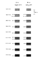
(通常印刷時)
図17Aは、通常印刷時のドットの形成順序の説明図である。なお、オーバーラップ方式の通常印刷については、図12A及び図12Bを用いて既に説明されている。すなわち、オーバーラップ方式の通常印刷では、180個のノズルのうちの178個のノズル(ノズル♯1〜ノズル♯178)が用いられ、搬送量Fは、89・Dである。
(Normal printing)
FIG. 17A is an explanatory diagram of the dot formation order during normal printing. Note that overlap-type normal printing has already been described with reference to FIGS. 12A and 12B. That is, in the normal printing of the overlap method, 178 nozzles (
ここでは、図12Aの領域2に焦点をあてて、ドットの形成順序を説明する。
1回目のパス(ドット形成動作)の前は、図17Aの「1回目のパス前」に示されるように、ドットが形成されていない。領域2では、ヘッド41Bが移動方向に移動してインクを吐出することによって、領域2における1回目のパスが行われる。
Here, the dot formation order will be described focusing on the
Before the first pass (dot forming operation), as shown in “Before the first pass” in FIG. 17A, no dots are formed. In the
オーバーラップ方式では、1回のパスではラスタラインは完成せず、ヘッドは、ラスタラインのうちの偶数番目の画素又は奇数番目の画素のみに、ドットを形成する。本実施形態では、1回目のパスにおいて、ラスタラインの奇数番目の画素に、ヘッドがドットを形成するものとする。なお、1ドットおきにドットが形成されているラスタライン(偶数番目の画素又は奇数番目の画素のみにドットが形成されているラスタライン)を、「未完成ラスタライン」と呼ぶことにする。 In the overlap method, a raster line is not completed in one pass, and the head forms dots only in even-numbered pixels or odd-numbered pixels in the raster line. In the present embodiment, it is assumed that the head forms dots at odd-numbered pixels in the raster line in the first pass. A raster line in which dots are formed every other dot (raster line in which dots are formed only in even-numbered pixels or odd-numbered pixels) is referred to as an “incomplete raster line”.
1回目のパス後、図17Aの「1回目のパス後」に示されるように、領域2には、未完成ラスタラインがノズルピッチずつ離れて形成されている。図中の矢印は、領域2において1回目に形成された未完成ラスタラインの位置を示している。また、図中には、領域2のうち、ノズル♯178(インクを吐出可能な搬送方向最上流ノズル)及びノズル♯177により形成された未完成ラスタラインで挟まれる領域が、示されている。
After the first pass, as shown in “After the first pass” in FIG. 17A, incomplete raster lines are formed in the
次に、搬送ユニットが89・Dの搬送量にて紙を搬送方向に搬送する。これにより、領域2は、ヘッド41に対して、相対的に下流側に移動する。このときのヘッド41の相対的な位置は、図12Aのヘッド41Cに示される位置である。180個のノズルはノズルピッチ4・Dで配置されているため、搬送ユニットが89・Dで紙を搬送した後、1回目のパスで形成された未完成ラスタラインの「上流側」の位置に、ヘッド41のノズルが位置することになる。例えば、搬送後、ノズル♯155は、ノズル♯177が形成した未完成ラスタラインの「上流側」に位置している。
Next, the transport unit transports the paper in the transport direction by a transport amount of 89 · D. As a result, the
そのため、領域2における2回目のパスでは、図17Aの「2回目のパス後」に示されるように、既に形成されているラスタラインの「上流側」に隣接して、ラスタラインが形成される。例えば、ノズル♯155は、ノズル♯177が形成した未完成ラスタラインの「上流側」に隣接して、ラスタラインを形成する。但し、ここでノズル♯155が形成するラスタラインは、偶数番目の画素のみにドットが形成される未完成ラスタラインである。(なお、不図示ではあるが、ノズル♯156は、ノズル♯178が形成した未完成ラスタラインの「上流側」に隣接して、未完成ラスタラインを形成している。)
3回目のパス以降も同様に、搬送ユニットが89・Dの搬送量にて搬送するため、前回のパスで形成されたラスタラインの「上流側」に隣接して、ラスタラインが形成される。なお、5〜8回目のパスでは、1〜4回目のパスによって形成された未完成ラスタラインのドットを補完するように、ヘッドは、1ドットおきに間欠的にドットを形成する。
Therefore, in the second pass in the
Similarly, after the third pass, the transport unit transports with a transport amount of 89 · D, so a raster line is formed adjacent to the “upstream side” of the raster line formed in the previous pass. In the fifth to eighth passes, the head intermittently forms dots every other dot so as to complement the dots of the incomplete raster lines formed by the first to fourth passes.
[比較例3]
図17Bは、比較例3の上端印刷時のドット形成順序の説明図である。同図は、紙の上端付近に位置する領域のドットの形成順序を示している。説明のため図17Aと図17Bが紙面の左右方向に並んで描かれているが、実際には、図17Aに示される領域は、図17Bに示される領域(紙の上端付近に位置する領域)よりも、搬送方向上流側に位置する。
[Comparative Example 3]
FIG. 17B is an explanatory diagram of a dot formation order during upper end printing in Comparative Example 3. This figure shows the dot formation order in the region located near the top edge of the paper. 17A and 17B are drawn side by side in the horizontal direction of the drawing for the sake of explanation, but in reality, the region shown in FIG. 17A is the region shown in FIG. 17B (the region located near the top edge of the paper). Rather than the upstream side in the transport direction.
上記の通り、溝241に対向するノズルの数は30個(ノズル♯75〜ノズル♯104)である。上端印刷では、溝に対向するノズルからしかインクを吐出できないので、この30個のノズルしか使用できない。一方、上端印刷でオーバーラップ方式を行うためには、オーバーラップ方式の条件である「N/Mとkが互いに素の関係」を満たす必要がある。そこで、比較例3では、この条件を満たす最多の30個のノズル(ノズル♯75〜ノズル♯104)を使用する。
As described above, the number of nozzles facing the
インクを吐出可能なノズル数が30個の場合、搬送ユニットによる紙の搬送量は、15・Dになる。30個のノズルはノズルピッチ4・Dで配置されているため、搬送ユニットが15・Dで搬送した後、1回目のパスで形成された未完成ラスタラインの「下流側」の位置に、ヘッド41のノズルが位置することになる。例えば、搬送後、ノズル♯100は、ノズル♯104が形成した未完成ラスタラインの「下流側」に位置している。
When the number of nozzles that can eject ink is 30, the amount of paper transported by the transport unit is 15 · D. Since 30 nozzles are arranged at a nozzle pitch of 4 · D, after the transport unit transports at 15 · D, the head is positioned at the “downstream” position of the unfinished raster line formed in the first pass. 41 nozzles will be located. For example, after conveyance, the
そのため、上端付近の2回目のパスでは、図17Bの「2回目のパス後」に示されるように、既に形成されている未完成ラスタラインの「下流側」に隣接して、ラスタラインが形成される。例えば、ノズル♯100は、ノズル♯104が形成した未完成ラスタラインの「下流側」に隣接して、ラスタラインを形成する。但し、ここでノズル♯100が形成するラスタラインは、偶数番目の画素のみにドットが形成される未完成ラスタラインである。(なお、不図示ではあるが、ノズル♯99は、ノズル♯103が形成した未完成ラスタラインの「下流側」に隣接して、未完成ラスタラインを形成している。)
3回目のパス以降も同様に、搬送ユニットが15・Dの搬送量にて搬送するため、前回のパスで形成されたラスタラインの「下流側」に隣接して、ラスタラインが形成される。なお、5〜8回目のパスでは、1〜4回目のパスによって形成された未完成ラスタラインのドットを補完するように、ヘッドは、1ドットおきに間欠的にドットを形成する。
Therefore, in the second pass near the upper end, as shown in “after the second pass” in FIG. 17B, a raster line is formed adjacent to the “downstream side” of the already formed incomplete raster line. Is done. For example, the
Similarly, after the third pass, the transport unit transports with a transport amount of 15 · D, so a raster line is formed adjacent to the “downstream side” of the raster line formed in the previous pass. In the fifth to eighth passes, the head intermittently forms dots every other dot so as to complement the dots of the incomplete raster lines formed by the first to fourth passes.
図17Aのドット形成順序と図17Bのドット形成順序とを比較すると、1回目のパスで形成された未完成ラスタライン間のドットの形成順序が異なっていることが理解できる。例えば、図17Aでは、1回目のパスで形成された未完成ラスタライン間において、まず搬送方向下流側から未完成ラスタラインが形成され、その後、未完成ラスタのドットを補完するようにして、搬送方向下流側のラスタラインが形成されている。一方、図17Bでは、1回目のパスで形成された未完成ラスタライン間において、まず搬送方向上流側から未完成ラスタラインが形成され、その後、未完成ラスタラインのドットを補完するようにして、搬送方向上流側のラスタラインが形成されている。
比較例3のように、通常印刷時と上端印刷時(又は下端印刷時)のラスタラインの形成順序(ドットの形成順序)が異なると、領域によって画質が異なってしまい、印刷画像の画質が劣化する。
Comparing the dot formation order of FIG. 17A and the dot formation order of FIG. 17B, it can be understood that the dot formation order between unfinished raster lines formed in the first pass is different. For example, in FIG. 17A, an unfinished raster line is first formed from the downstream side in the transport direction between unfinished raster lines formed in the first pass, and then the dots of the unfinished raster are complemented. A raster line on the downstream side in the direction is formed. On the other hand, in FIG. 17B, between the incomplete raster lines formed in the first pass, an incomplete raster line is first formed from the upstream side in the transport direction, and then the dots of the incomplete raster line are complemented. A raster line on the upstream side in the transport direction is formed.
As in Comparative Example 3, if the raster line formation order (dot formation order) differs between normal printing and upper-end printing (or lower-end printing), the image quality differs depending on the region, and the print image quality deteriorates. To do.
(本実施形態の上端印刷)
図17Cは、本実施形態の上端印刷時のドットの形成順序の説明図である。同図は、紙の上端付近に位置する領域のドットの形成順序を示している。説明のため図17Aと図17Cが紙面の左右方向に並んで描かれているが、実際には、図17Aに示される領域は、図17Cに示される領域(紙の上端付近に位置する領域)よりも、搬送方向上流側に位置する。
(Upper end printing of this embodiment)
FIG. 17C is an explanatory diagram of a dot formation order during upper-end printing according to the present embodiment. This figure shows the dot formation order in the region located near the top edge of the paper. 17A and 17C are drawn side by side in the left-right direction on the paper surface for explanation, but in reality, the region shown in FIG. 17A is the region shown in FIG. 17C (the region located near the top edge of the paper). Rather than the upstream side in the transport direction.
上記の通り、上端印刷では、30個のノズル(ノズル♯75〜ノズル♯104)しか使用できない。一方、上端印刷でオーバーラップ方式を行うためには、オーバーラップ方式の条件である「N/MとNが互いに素の関係」を満たす必要がある。但し、この条件を満たす最多の30個のノズルを使用すると、上記の比較例の通り、通常印刷時と異なるドット形成順序になってしまう。 As described above, only 30 nozzles (nozzle # 75 to nozzle # 104) can be used in the upper end printing. On the other hand, in order to perform the overlap method in the upper end printing, it is necessary to satisfy the condition of the overlap method “N / M and N are relatively prime”. However, if the maximum of 30 nozzles satisfying this condition are used, the dot formation order is different from that during normal printing as in the above comparative example.
そこで、本実施形態では、26個のノズル(ノズル♯75〜ノズル♯100)を使用する。すなわち、N/M(使用するノズル数/オーバーラップ数)をkで割ったときの余りが、通常印刷及び上端印刷で等しくなるようにする。本実施形態の通常印刷では、使用するノズル数が178であり、オーバーラップ数が2であり、kが4であるので、N/Mをkで割ったときの余りは1になる。一方、本実施形態の上端印刷では、使用するノズル数Nが26であり、オーバーラップ数が2であり、kが4であるので、N/Mをkで割ったときの余りは1になり、通常印刷時と等しい。なお、前述の比較例3の上端印刷では、この余りは3になり、通常印刷時とは異なっていた。 Therefore, in this embodiment, 26 nozzles (nozzle # 75 to nozzle # 100) are used. That is, the remainder when N / M (number of nozzles used / number of overlaps) is divided by k is made equal in normal printing and top-end printing. In the normal printing of this embodiment, the number of nozzles used is 178, the number of overlaps is 2, and k is 4, so the remainder when N / M is divided by k is 1. On the other hand, in the upper end printing of this embodiment, the number of nozzles N to be used is 26, the number of overlaps is 2, and k is 4, so the remainder when N / M is divided by k is 1. It is equal to normal printing. In the upper end printing of Comparative Example 3 described above, this remainder is 3, which is different from that during normal printing.
インクを吐出可能なノズル数が26個の場合、搬送ユニットによる紙の搬送量は、13・Dになる。26個のノズルはノズルピッチ4・Dで配置されているため、搬送ユニットが13・Dで紙を搬送した後、1回目のパスで形成された未完成ラスタラインの「上流側」の位置に、ヘッド41のノズルが位置することになる。例えば、搬送後、ノズル♯96は、ノズル♯99が形成した未完成ラスタラインの「上流側」に位置している。
When the number of nozzles that can eject ink is 26, the amount of paper transported by the transport unit is 13 · D. Since the 26 nozzles are arranged at a nozzle pitch of 4 · D, after the transport unit transports the paper at 13 · D, it is positioned at the “upstream” position of the unfinished raster line formed in the first pass. The nozzle of the
そのため、上端付近の2回目のパスでは、図17Cの「2回目のパス後」に示されるように、既に形成されているラスタラインの「上流側」に隣接して、ラスタラインが形成される。例えば、ノズル♯96は、ノズル♯99が形成したラスタラインの「上流側」に隣接して、ラスタラインを形成する。但し、ここでノズル♯96が形成するラスタラインは、偶数番目の画素のみにドットが形成される未完成ラスタラインである。(なお、不図示ではあるが、ノズル97は、ノズル♯100が形成した未完成ラスタラインの「上流側」に隣接して、未完成ラスタラインを形成している。)
3回目のパス以降も同様に、搬送ユニットが13・Dの搬送量にて搬送するため、前回のパスで形成されたラスタラインの「上流側」に隣接して、ラスタラインが形成される。なお、5〜8回目のパスでは、1〜4回目のパスによって形成された未完成ラスタラインのドットを補完するように、ヘッドは、1ドットおきに間欠的にドットを形成する。
Therefore, in the second pass near the upper end, a raster line is formed adjacent to the “upstream side” of the already formed raster line, as shown in “after the second pass” in FIG. 17C. . For example, the nozzle # 96 forms a raster line adjacent to the “upstream side” of the raster line formed by the
Similarly, after the third pass, the transport unit transports with a transport amount of 13 · D, so that a raster line is formed adjacent to the “upstream side” of the raster line formed in the previous pass. In the fifth to eighth passes, the head intermittently forms dots every other dot so as to complement the dots of the incomplete raster lines formed by the first to fourth passes.
図17Aのドット形成順序と図17Cのドット形成順序とを比較すると、1回目のパスで形成された未完成ラスタライン間のドットの形成順序が同じであることが理解できる。例えば、図17Aでは、1回目のパスで形成されたラスタライン間において、まず搬送方向下流側から未完成ラスタラインが形成され、その後、未完成ラスタのドットを補完するようにして、搬送方向下流側のラスタラインが形成されている。同様に、図17Cでも、1回目のパスで形成された未完成ラスタライン間において、まず搬送方向下流側から未完成ラスタラインが形成され、その後、未完成ラスタラインのドットを補完するようにして、搬送方向下流側のラスタラインが形成されている。 Comparing the dot formation order of FIG. 17A and the dot formation order of FIG. 17C, it can be understood that the dot formation order between unfinished raster lines formed in the first pass is the same. For example, in FIG. 17A, an unfinished raster line is first formed from the downstream side in the transport direction between the raster lines formed in the first pass, and then the dots of the unfinished raster are complemented to downstream in the transport direction. A raster line on the side is formed. Similarly, in FIG. 17C, an incomplete raster line is first formed from the downstream side in the transport direction between the incomplete raster lines formed in the first pass, and then the dots of the incomplete raster line are complemented. A raster line on the downstream side in the transport direction is formed.
このように、本実施形態では、通常印刷時と上端印刷時(又は下端印刷時)のドットの形成順序が同じである。そのため、上端印刷と通常印刷とにより1枚の紙に印刷画像が印刷されても、どの領域でも画質がほぼ等しく、印刷画像全体の画質が向上する。 As described above, in this embodiment, the dot formation order is the same during normal printing and during upper-end printing (or during lower-end printing). Therefore, even if a print image is printed on one sheet of paper by top-end printing and normal printing, the image quality is almost the same in any region, and the image quality of the entire print image is improved.
[比較例4]
前述のインターレース方式の実施形態及びオーバーラップ方式の実施形態では、N/Mをkで割ったときの余りが、通常印刷及び上端印刷で等しくなるようにしていた。これにより、通常印刷におけるラスタラインの形成順序と、上端印刷におけるラスタラインの形成順序とを、等しく印刷することが可能になっている。
但し、オーバーラップ方式の場合、「N/Mをkで割ったときの余りが、通常印刷及び上端印刷で等しくなる」との条件を満たしただけでは、通常印刷と上端印刷のドット形成順序は、必ずしも等しくならない。以下に、この点を詳しく説明する。
[Comparative Example 4]
In the interlaced embodiment and the overlapped embodiment described above, the remainder when N / M is divided by k is made equal in normal printing and top-end printing. As a result, the raster line formation order in normal printing and the raster line formation order in upper-end printing can be printed equally.
However, in the overlap method, the dot formation order of normal printing and top-end printing is as long as the condition that “the remainder when N / M is divided by k is equal in normal printing and top-end printing” is satisfied. , Not necessarily equal. This point will be described in detail below.
図18A及び図18Bは、オーバーラップ方式のドット形成順序の説明図である。図18Aは、本実施形態の上端印刷時のドットの形成順序の説明図である。そのため、図18Aは、前述の図17Cと同じである。
図18Bは、比較例4の上端印刷時のドットの形成順序の説明図である。比較例4では、本実施形態の上端印刷と同様に、26個のノズル(ノズル♯75〜ノズル♯100)を使用し、搬送ユニットが搬送量13・Dにて紙を搬送する。そのため、比較例4では、「N/Mをkで割ったときの余りが、通常印刷及び上端印刷で等しくなる」との条件を満たしている。これにより、比較例4においても、搬送後、既に形成されている未完成ラスタラインとノズルとの位置関係が、通常印刷及び上端印刷で等しくなる(本実施形態の上端印刷と同じである)。
18A and 18B are explanatory diagrams of the dot formation order of the overlap method. FIG. 18A is an explanatory diagram of a dot formation order during upper end printing according to the present embodiment. Therefore, FIG. 18A is the same as FIG. 17C described above.
FIG. 18B is an explanatory diagram of the dot formation order during upper end printing in Comparative Example 4. In Comparative Example 4, as in the upper end printing of the present embodiment, 26 nozzles (nozzle # 75 to nozzle # 100) are used, and the transport unit transports the paper with a transport amount of 13 · D. Therefore, in Comparative Example 4, the condition that “the remainder when N / M is divided by k is equal between normal printing and top-end printing” is satisfied. Thereby, also in the comparative example 4, the positional relationship between the unfinished raster lines and the nozzles already formed after the conveyance becomes equal in the normal printing and the upper end printing (the same as the upper end printing in the present embodiment).
しかし、比較例4は、本実施形態の上端印刷と比較すると、ヘッドがドットを形成する位置が異なっている。
すなわち、本実施形態の上端印刷では、通常印刷と同様に、ヘッドは、1回目のパスで「奇数番目」の画素にドットを形成し、2回目のパスで「偶数番目」の画素にドットを形成し、3回目のパスで「奇数番目」の画素にドットを形成し、4回目のパスで「偶数番目」の画素にドットを形成している。そして、5〜8回目のパスでは、1〜4回目のパスにより形成された未完成ラスタラインのドットを補完するため、ヘッドは、5回目のパスでは「偶数番目」、6回目のパスでは「奇数番目」、7回目のパスでは「偶数番目」、8回目のパスでは「奇数番目」の画素に、ドットを形成する。つまり、本実施形態の上端印刷では、ヘッドは、連続する4回のパスにおいて交互に「偶数番目」又は「奇数番目」の画素にドットを形成し、その後に連続する4回のパスでは順序を入れ替えて交互に「偶数番目」又は「奇数番目」の画素にドットを形成する。
However, the comparative example 4 is different from the upper end printing of the present embodiment in the position where the head forms dots.
That is, in the upper end printing of the present embodiment, as in normal printing, the head forms dots on “odd-numbered” pixels in the first pass, and dots on “even-numbered” pixels in the second pass. In the third pass, dots are formed in “odd-numbered” pixels, and in the fourth pass, dots are formed in “even-numbered” pixels. In the fifth to eighth passes, in order to complement the dots of the unfinished raster lines formed by the first to fourth passes, the head is “even number” in the fifth pass and “ Dots are formed on “odd-numbered” pixels, “even-numbered” pixels in the seventh pass, and “odd-numbered” pixels in the eighth pass. That is, in the upper end printing of the present embodiment, the head alternately forms dots on the “even-numbered” or “odd-numbered” pixels in four consecutive passes, and the order is repeated in the four consecutive passes thereafter. The dots are alternately formed to form dots at “even-numbered” or “odd-numbered” pixels.
一方、比較例4の上端印刷では、通常印刷とは異なり、1〜4回目のパスにおいて、ヘッドは、全て「奇数番目」の画素にドットを形成する。そして、5〜8回目のパスでは、1〜4回目のパスにより形成された未完成ラスタラインのドットを補完するため、ヘッドは、全て「偶数番目」の画素にドットを形成する。
そのため、比較例4では、通常印刷時と上端印刷時(又は下端印刷時)のドットの形成順序が異なるため、領域によって画質が異なってしまい、印刷画像の画質が劣化する。
On the other hand, in the upper end printing of Comparative Example 4, unlike the normal printing, the heads form dots on all “odd-numbered” pixels in the first to fourth passes. In the fifth to eighth passes, in order to complement the dots of the incomplete raster lines formed in the first to fourth passes, the head forms dots on all “even-numbered” pixels.
Therefore, in Comparative Example 4, since the dot formation order is different between normal printing and upper-end printing (or lower-end printing), the image quality differs depending on the region, and the image quality of the printed image deteriorates.
つまり、図18Aと図18Bは、ラスタラインの形成順序が等しいが、ドットの形成順序が異なる。このような場合、通常印刷時と上端印刷時(又は下端印刷時)のドットの形成順序が等しい図18Aの方が、画質が向上するので望ましい。 That is, FIG. 18A and FIG. 18B have the same raster line formation order but different dot formation order. In such a case, FIG. 18A in which the dot formation order in normal printing and upper-end printing (or lower-end printing) is the same is preferable because the image quality is improved.
<オーバーラップ方式について2>
前述のオーバーラップ方式では、同じパスにおいてヘッドの全てのノズルは、偶数番目の画素又は奇数番目の画素の一方のみにドットを形成している(つまり、全てのノズルは、移動方向に同じ位置の画素にドットを形成している)。しかし、このようなドットの形成方法では、通常印刷によりドットが形成される領域のドット形成順序と、上端印刷(又は下端印刷)によりドットが形成される領域のドット形成順序とが、一部しか完全一致しない。以下に詳しく説明する。
<About the
In the above-described overlap method, all nozzles of the head in the same pass form dots only in one of even-numbered pixels or odd-numbered pixels (that is, all nozzles are located at the same position in the movement direction). Dots are formed on the pixels). However, in such a dot formation method, only a part of the dot formation order of the area where the dots are formed by normal printing and the dot formation order of the areas where the dots are formed by top-end printing (or bottom-end printing). Does not match exactly. This will be described in detail below.
図19Aは、前述のオーバーラップ方式による領域2のドット形成の説明図である。図19Bは、前述のオーバーラップ方式による領域3のドット形成の説明図である。図20Aは、前述のオーバーラップ方式のドット形成の説明図である。図中のヘッド内の「奇」との記載は、そのヘッドが奇数番目の画素にドットを吐出することを意味する。また、図中のヘッド内の「偶」との記載は、そのヘッドが偶数番目の画素にドットを吐出することを意味する。また、図中の紙面の「奇→偶」という記載は、奇数番目の画素へのドット形成動作の後に、偶数番目の画素へのドット形成動作が行われることを意味する。
FIG. 19A is an explanatory diagram of dot formation in the
前述の実施形態では、ヘッド41Bがヘッド41Jの位置まで間欠的に移動するたびに、ヘッドは、「奇数(番目の画素)」→「偶数(番目の画素)」→「奇数」→「偶数」→「偶数」→「奇数」→「偶数」→「奇数」…の順に画素にドットを形成する(図20Aの左側を参照)。この場合、紙上の領域2では、「奇数(番目の画素)」→「偶数(番目の画素)」→「奇数」→「偶数」→「偶数」→「奇数」→「偶数」→「奇数」の順にドットが形成される(図20Aの右側の領域2を参照)。しかし、紙上の領域3では、「偶数(番目の画素)」→「奇数(番目の画素)」→「偶数」→「偶数」→「奇数」→「偶数」→「奇数」→「奇数」の順にドットが形成される(図20Aの右側の領域3を参照)。
In the above-described embodiment, each time the
図19A及び図19Bを比較すると、ラスタラインの形成順序は同じであるが、移動方向のドットの位置が異なっている。例えば、両者の「5回目のパス後」のドット形成の様子を比較すると、ドットの形成状況が異なっている。図19Aでは格子状にドットが配置されているが、図19Bでは格子状にドットが配置されていない。 Comparing FIG. 19A and FIG. 19B, the raster line formation order is the same, but the dot positions in the movement direction are different. For example, when the state of dot formation “after the fifth pass” is compared, the dot formation state is different. In FIG. 19A, dots are arranged in a grid pattern, but in FIG. 19B, dots are not arranged in a grid pattern.
このように、同じ印刷処理が行われる領域(この場合、通常印刷が行われる領域2と領域3)の間でドットの形成順序が異なっているのでは、通常印刷によりドットが形成される領域のドット形成順序と、上端印刷(又は下端印刷)によりドットが形成される領域のドット形成順序とが、一部しか一致しない。(但し、ドット形成順序は異なっているが、ラスタラインの形成順序は等しい。)
そこで、本改良例では、ヘッドは、移動方向に異なる位置の画素にドットを形成している。つまり、改良例では、あるノズルが偶数番目の画素にドットを形成し、他のノズルが奇数番目の画素にドットを形成する。これにより、以下のようにして、全ての印刷領域でドットの形成順序が等しくなるようにしている。
As described above, if the dot formation order is different between the areas where the same printing process is performed (in this case, the
Therefore, in this improved example, the head forms dots on pixels at different positions in the movement direction. That is, in the improved example, a certain nozzle forms dots on even-numbered pixels, and another nozzle forms dots on odd-numbered pixels. Thereby, the dot formation order is made equal in all the print areas as follows.
図19Cは、改良例のオーバーラップ方式による領域3のドット形成の説明図である。図20Bは、改良例のオーバーラップ方式のドット形成の説明図である。
この改良例では、1つのノズル群の180個のノズルが、それぞれ8つのグループに分類されている。以下の説明では、搬送方向に最も下流側のグループを第1グループと称し、順番にグループに番号を付し、搬送方向に最も上流側のグループを第8グループと称する。具体的には、第1グループはノズル♯1〜ノズル♯22からなり、第2グループはノズル♯23〜ノズル♯44からなり、第3グループはノズル♯45〜ノズル♯66からなり、第4グループはノズル♯67〜ノズル♯89からなり、第5グループはノズル♯90〜ノズル♯111からなり、第6グループはノズル♯112〜ノズル133からなり、第7グループはノズル♯134〜ノズル♯155からなり、第8グループはノズル♯156〜ノズル♯178からなる。
FIG. 19C is an explanatory diagram of dot formation in the
In this improved example, 180 nozzles of one nozzle group are classified into eight groups. In the following description, the most downstream group in the transport direction is referred to as a first group, the groups are numbered in order, and the most upstream group in the transport direction is referred to as an eighth group. Specifically, the first group includes
そして、同じグループ内の全てのノズルは、移動方向に同じ位置の画素にドットを形成する。例えば、同じグループ内の全てのノズルは、偶数番目の画素にドットを形成する。また、異なるグループのノズルは、移動方向に異なる位置の画素にドットを形成可能である。例えば、第1グループのノズルが奇数番目の画素にドットを形成するとき、第2グループのノズルは偶数番目の画素にドットを形成可能である。 All nozzles in the same group form dots at pixels at the same position in the movement direction. For example, all nozzles in the same group form dots at even-numbered pixels. Further, different groups of nozzles can form dots at pixels at different positions in the movement direction. For example, when the first group of nozzles forms dots at odd-numbered pixels, the second group of nozzles can form dots at even-numbered pixels.
本改良例では、第1グループは奇数番目の画素にドットを形成し、第2グループは偶数番目の画素にドットを形成し、第3グループは奇数番目の画素にドットを形成し、第4グループは偶数番目の画素にドットを形成し、第5グループは偶数番目の画素にドットを形成し、第6グループは奇数番目の画素にドットを形成し、第7グループは偶数番目の画素にドットを形成し、第8グループは奇数番目の画素にドットを形成する。
これにより、オーバーラップ方式によって通常印刷される全ての領域において、ドットの形成順序が同じになる。すなわち、全ての領域において、「奇数(番目の画素)」→「偶数(番目の画素)」→「奇数」→「偶数」→「偶数」→「奇数」→「偶数」→「奇数」の順にドットが形成される。
In this improved example, the first group forms dots on odd-numbered pixels, the second group forms dots on even-numbered pixels, the third group forms dots on odd-numbered pixels, and the fourth group Forms dots on even-numbered pixels, the fifth group forms dots on even-numbered pixels, the sixth group forms dots on odd-numbered pixels, and the seventh group forms dots on even-numbered pixels. In the eighth group, dots are formed in odd-numbered pixels.
As a result, the dot formation order is the same in all areas that are normally printed by the overlap method. That is, in all regions, “odd number (th pixel)” → “even number (th pixel)” → “odd number” → “even number” → “even number” → “odd number” → “even number” → “odd number” in this order. Dots are formed.
また、不図示であるが、上端印刷及び下端印刷も同様に、インクを吐出する26個のノズルが、8つのグループに分類される。そして、第1グループが「奇数」番目の画素にドットを形成し、第2グループが「偶数」番目の画素にドットを形成し、第3グループが「奇数」番目の画素にドットを形成し、第4グループが「偶数」番目の画素にドットを形成し、第5グループが「偶数」番目の画素にドットを形成し、第6グループが「奇数」番目の画素にドットを形成し、第7グループが「偶数」番目の画素にドットを形成し、第8グループが「奇数」番目の画素にドットを形成する。
これにより、ラスタラインの形成順序が一致するだけでなく、ドットの形成順序も一致する。
In addition, although not shown, in the upper end printing and the lower end printing, similarly, 26 nozzles that eject ink are classified into eight groups. The first group forms dots on the “odd” pixels, the second group forms dots on the “even” pixels, the third group forms dots on the “odd” pixels, The fourth group forms dots at “even” pixels, the fifth group forms dots at “even” pixels, the sixth group forms dots at “odd” pixels, The group forms dots at “even” pixels, and the eighth group forms dots at “odd” pixels.
As a result, not only the raster line formation order matches, but also the dot formation order matches.
===その他の実施の形態===
上記の実施形態は、主としてプリンタについて記載されているが、その中には、印刷装置、記録装置、液体の吐出装置、印刷方法、記録方法、液体の吐出方法、印刷システム、記録システム、コンピュータシステム、プログラム、プログラムを記憶した記憶媒体、表示画面、画面表示方法、印刷物の製造方法、等の開示が含まれていることは言うまでもない。
=== Other Embodiments ===
The above-described embodiment is mainly described for a printer. Among them, a printing apparatus, a recording apparatus, a liquid ejection apparatus, a printing method, a recording method, a liquid ejection method, a printing system, a recording system, and a computer system are included. Needless to say, the disclosure includes a program, a storage medium storing the program, a display screen, a screen display method, a printed material manufacturing method, and the like.
また、一実施形態としてのプリンタ等を説明したが、上記の実施形態は、本発明の理解を容易にするためのものであり、本発明を限定して解釈するためのものではない。本発明は、その趣旨を逸脱することなく、変更、改良され得ると共に、本発明にはその等価物が含まれることは言うまでもない。特に、以下に述べる実施形態であっても、本発明に含まれるものである。 Moreover, although the printer etc. as one embodiment were demonstrated, said embodiment is for making an understanding of this invention easy, and is not for limiting and interpreting this invention. The present invention can be changed and improved without departing from the gist thereof, and it is needless to say that the present invention includes equivalents thereof. In particular, the embodiments described below are also included in the present invention.
<プリンタについて>
前述の実施形態では、プリンタが説明されていたが、これに限られるものではない。例えば、カラーフィルタ製造装置、染色装置、微細加工装置、半導体製造装置、表面加工装置、三次元造形機、液体気化装置、有機EL製造装置(特に高分子EL製造装置)、ディスプレイ製造装置、成膜装置、DNAチップ製造装置などのインクジェット技術を応用した各種の記録装置に、本実施形態と同様の技術を適用しても良い。また、これらの方法や製造方法も応用範囲の範疇である。このような分野に本技術を適用しても、液体を対象物に向かって直接的に吐出(直描)することができるという特徴があるので、従来と比較して省材料、省工程、コストダウンを図ることができる。
<About the printer>
In the above-described embodiment, the printer has been described. However, the present invention is not limited to this. For example, color filter manufacturing apparatus, dyeing apparatus, fine processing apparatus, semiconductor manufacturing apparatus, surface processing apparatus, three-dimensional modeling machine, liquid vaporizer, organic EL manufacturing apparatus (particularly polymer EL manufacturing apparatus), display manufacturing apparatus, film formation The same technique as that of the present embodiment may be applied to various recording apparatuses to which an ink jet technique is applied such as an apparatus and a DNA chip manufacturing apparatus. These methods and manufacturing methods are also within the scope of application. Even if this technology is applied to such a field, the liquid can be directly ejected (directly drawn) toward the object. You can go down.
<インクについて>
前述の実施形態は、プリンタの実施形態だったので、染料インク又は顔料インクをノズルから吐出していた。しかし、ノズルから吐出する液体は、このようなインクに限られるものではない。例えば、金属材料、有機材料(特に高分子材料)、磁性材料、導電性材料、配線材料、成膜材料、電子インク、加工液、遺伝子溶液などを含む液体(水も含む)をノズルから吐出しても良い。このような液体を対象物に向かって直接的に吐出すれば、省材料、省工程、コストダウンを図ることができる。
<About ink>
Since the above-described embodiment is an embodiment of a printer, dye ink or pigment ink is ejected from the nozzle. However, the liquid ejected from the nozzle is not limited to such ink. For example, liquids (including water) including metal materials, organic materials (especially polymer materials), magnetic materials, conductive materials, wiring materials, film-forming materials, electronic inks, processing liquids, gene solutions, etc. are ejected from nozzles. May be. If such a liquid is directly discharged toward the object, material saving, process saving, and cost reduction can be achieved.
<ノズルについて>
前述の実施形態では、圧電素子を用いてインクを吐出していた。しかし、液体を吐出する方式は、これに限られるものではない。例えば、熱によりノズル内に泡を発生させる方式など、他の方式を用いてもよい。
<About nozzle>
In the above-described embodiment, ink is ejected using a piezoelectric element. However, the method for discharging the liquid is not limited to this. For example, other methods such as a method of generating bubbles in the nozzle by heat may be used.
<インターレース方式について>
前述の実施形態では、180dpi(4・D)のノズルピッチのノズル群を用いて、720dpi間隔のドットを形成するインターレース方式が行われていた。しかし、インターレース方式は、これに限られるものではない。例えば、720dpi(D)のノズルピッチのノズル群を用いて、インターレース方式が行われてもよい。
<About the interlace method>
In the above-described embodiment, an interlace method is used in which dots having a 720 dpi interval are formed using a nozzle group having a nozzle pitch of 180 dpi (4 · D). However, the interlace method is not limited to this. For example, the interlace method may be performed using a nozzle group having a nozzle pitch of 720 dpi (D).
図21は、他のインターレース方式の説明図である。本実施形態では、ノズル群の複数のノズルは、搬送方向に沿って、720dpi(=1/720インチ)にて配列されている。紙に720dpi間隔でドットを形成するとき、k=1になる。本実施形態では、説明の簡略化のため、ノズル群は24個のノズルを有している。そして、紙は一定の間隔4・Dにて搬送されている。また、4個おきにノズルからインクを吐出し、各パスごとに、インクを吐出するノズルを変えている。 FIG. 21 is an explanatory diagram of another interlace method. In the present embodiment, the plurality of nozzles of the nozzle group are arranged at 720 dpi (= 1/720 inch) along the transport direction. When dots are formed on the paper at 720 dpi intervals, k = 1. In this embodiment, the nozzle group has 24 nozzles for simplification of description. The paper is conveyed at a constant interval of 4 · D. Also, ink is ejected from the nozzles every four nozzles, and the nozzles that eject ink are changed for each pass.
本実施形態でも、1回のパスで記録されるラスタラインの間に記録されないラスタラインが挟まれるように、インターレース方式を行うことができる。また、本実施形態では、前述の実施形態のような「インクを吐出可能なノズル数N(整数)はkと互いに素の関係」等の制約はない(但し、他の制約はある)。 Also in this embodiment, the interlace method can be performed so that raster lines that are not recorded are sandwiched between raster lines that are recorded in one pass. Further, in the present embodiment, there is no restriction such as “the number N of nozzles that can eject ink (integer) is relatively prime to k” as in the above-described embodiment (however, there are other restrictions).
===まとめ===
(1)前述のプリンタ(印刷装置)は、紙(媒体)を搬送方向に搬送する搬送ユニットと、搬送方向に並ぶ複数のノズルを移動方向に移動させるキャリッジ(移動体)と、を備えている。そして、このプリンタは、通常印刷(第1印刷処理)と上端印刷又は下端印刷(第2印刷処理)とを行うことができる。ここで、通常印刷では、所定の搬送量にて搬送ユニットが紙を搬送する搬送動作と、移動する複数のノズルからインクを吐出して複数のドット列を紙に形成するドット形成動作と、を繰り返す。また、上端印刷又は下端印刷では、通常印刷よりも少ない搬送量にて搬送ユニットが紙を搬送する搬送動作と、移動する複数の前記ノズルからインクを吐出して複数のドット列を紙に形成するドット形成動作と、を繰り返す。
=== Summary ===
(1) The above-described printer (printing apparatus) includes a transport unit that transports paper (medium) in the transport direction, and a carriage (moving body) that moves a plurality of nozzles arranged in the transport direction in the movement direction. . The printer can perform normal printing (first printing process) and upper-end printing or lower-end printing (second printing process). Here, in normal printing, a transport operation in which the transport unit transports paper with a predetermined transport amount, and a dot formation operation in which ink is ejected from a plurality of moving nozzles to form a plurality of dot rows on the paper. repeat. In top-end printing or bottom-end printing, a transport operation in which the transport unit transports the paper with a transport amount smaller than that in normal printing and a plurality of dot rows are formed on the paper by ejecting ink from the plurality of moving nozzles. The dot forming operation is repeated.
このように、通常印刷と上端印刷(及び下端印刷)により印刷画像を紙に形成すると、この印刷画像には、通常印刷により印刷される領域と、下端印刷により印刷される領域とが存在する。
しかし、通常印刷と上端印刷(及び下端印刷)の印刷品質が異なると、両領域の画質の差が目立ち、印刷画像全体の画質が悪くなる。
As described above, when a print image is formed on paper by normal printing and top-end printing (and bottom-end printing), the print image includes a region printed by normal printing and a region printed by bottom-end printing.
However, if the print quality differs between normal printing and upper-end printing (and lower-end printing), the difference in image quality between the two areas is noticeable, and the image quality of the entire printed image is deteriorated.
そこで、前述のプリンタでは、1回のドット形成動作で形成されるラスタライン又は未完成ラスタライン(ドット列)の間に、他のドット形成動作で形成されるラスタラインが複数はさまれており、この挟まれている複数のラスタラインの通常印刷における形成動作が、下端印刷における形成順序と等しいこととしている。例えば、前述の図15に示されるインターレース方式によれば、通常印刷においてノズル♯179とノズル♯178とにより形成された2つのラスタラインに挟まれる3つのラスタラインは、搬送方向上流側から順に形成されており、上端印刷(又は下端印刷)においてノズル♯101とノズル100とにより形成された2つのラスタラインに挟まれる3つのラスタラインは、搬送方向上流側から順に形成されている。
Therefore, in the above-described printer, a plurality of raster lines formed by other dot forming operations are sandwiched between raster lines formed by one dot forming operation or unfinished raster lines (dot rows). The forming operation in normal printing of a plurality of sandwiched raster lines is the same as the forming order in bottom-end printing. For example, according to the interlace method shown in FIG. 15, the three raster lines sandwiched between the two raster lines formed by the
これにより、上端印刷(又は下端印刷)による印刷画像の画質が、通常印刷の印刷画像の画質に近づき、印刷画像全体の画質が向上する。
すなわち、印刷画像は、ノズルから吐出されたインクにより形成されるので、印刷画像を構成するインクの乾き方が異なれば、印刷画像の画質が異なってくる。そして、この印刷画像は、搬送方向に並ぶ複数のラスタラインから構成される。そのため、両印刷処理におけるラスタラインの形成順序が等しければ、インクの乾き方がほぼ同様になるので、各印刷処理により形成される印刷画像の画質が同質になる。これにより、印刷画像全体の画質が向上する。
As a result, the image quality of the print image by the upper end printing (or the lower end print) approaches the image quality of the normal print image, and the image quality of the entire print image is improved.
In other words, since the print image is formed by the ink ejected from the nozzles, the image quality of the print image differs if the way of drying the ink constituting the print image is different. The print image is composed of a plurality of raster lines arranged in the transport direction. For this reason, if the raster lines are formed in the same order in both printing processes, the ink is dried in substantially the same manner, and the image quality of the printed image formed by each printing process is the same. Thereby, the image quality of the entire printed image is improved.
(2)前述のインターレース方式によれば、プリンタは、1回のドット形成動作により、移動方向に連続する画素にドットを形成している。つまり、プリンタは、1回のドット形成動作により、ラスタラインを完成させている。これにより、プリンタは、印刷画像全体の画質を高めつつ、高速な印刷を行うことができる。 (2) According to the interlace method described above, the printer forms dots on pixels that are continuous in the movement direction by a single dot formation operation. That is, the printer completes the raster line by one dot forming operation. As a result, the printer can perform high-speed printing while improving the image quality of the entire print image.
(3)前述の図15A及び図15Cに示されるインターレース方式によれば、ドットピッチ(紙に形成されるドットの間隔)が1/720インチ(=D)、ノズルピッチ(インクを吐出するノズルの搬送方向の間隔)が1/180インチ(=4・D)、通常印刷(第1印刷処理)におけるインクを吐出するノズル数N1が179、上端印刷又は下端印刷(第2印刷処理)におけるインクを吐出するノズル数N2が27である。また、前述の図16A及び図16Cに示されるインターレース方式2によれば、ドットピッチが1/1440インチ(=D)、ノズルピッチが1/180インチ(=8/D)、通常印刷におけるインクを吐出するノズル数N1が179、上端印刷又は下端印刷におけるインクを吐出するノズル数N2が27である。つまり、いずれのインターレース方式とも、N1とkが互いに素の関係にあり、N2とkが互いに素の関係にあり、N1をkで割ったときの余りが、N2をkで割ったときの余りと等しい。
(3) According to the interlace method shown in FIGS. 15A and 15C described above, the dot pitch (the interval between dots formed on the paper) is 1/720 inch (= D), and the nozzle pitch (the number of nozzles that eject ink). (Interval in the transport direction) is 1/180 inch (= 4 · D), the number of nozzles N1 ejecting ink in normal printing (first printing process) is 179, and ink in upper end printing or lower end printing (second printing process) The number N2 of nozzles to be discharged is 27. Further, according to the
前述の実施形態ではこの条件を満たしているので、1回のドット形成動作で形成されるラスタライン(ドット列)の間に、他のドット形成動作で形成されるラスタラインが複数はさまれるようなインターレース方式が可能になる。また、この挟まれている複数のラスタラインの通常印刷における形成動作が、下端印刷における形成順序と等しくなる。これにより、印刷画像全体の画質が向上する。
但し、上記の条件を満たさなければ効果が得られない訳ではない。例えば、図21に示されるように、4個おきにノズルからインクを吐出し、ドット形成動作毎にインクを吐出するノズルを変えてもよい。要するに、通常印刷におけるラスタラインの形成動作が、下端印刷における形成順序と等しくなっていればよいのである。
In the above-described embodiment, this condition is satisfied, so that a plurality of raster lines formed by other dot forming operations are sandwiched between raster lines (dot rows) formed by one dot forming operation. Interlace method becomes possible. In addition, the forming operation in normal printing of the sandwiched raster lines is the same as the forming order in bottom edge printing. Thereby, the image quality of the entire printed image is improved.
However, the effect cannot be obtained unless the above conditions are satisfied. For example, as shown in FIG. 21, ink may be ejected from nozzles every four nozzles, and the nozzles that eject ink may be changed for each dot forming operation. In short, it is sufficient that the raster line forming operation in the normal printing is equal to the forming order in the lower end printing.
(4)仮に、k=4のように、kが、1又はk−1以外に、kより小さい自然数と互いに素の関係がない場合、ラスタラインの形成順序が異なっていても、印刷画像の著しい劣化はない。なぜなら、図15A及び図15Cを比較して分かるとおり、いずれの印刷も、「前回のドット形成動作で形成されたラスタラインの隣に、次のドット形成動作で形成されるラスタラインが位置する」という点で共通しているからである。
しかし、前述の図16A及び図16Cに示されるインターレース方式によれば、前述の図16A及び図16Cでは、k=8であり、1又は7以外に、3及び5が8と互いに素の関係にある。つまり、kが、1又はk−1以外に、kより小さい自然数と互いに素の関係にある。このような場合、図16Bと図16Cとを比較して分かるとおり、ラスタラインの形成順序の差が大きくなり、印刷画像が著しく劣化する恐れがある。
そのため、kが、1又はk−1以外に、kより小さい自然数と互いに素の関係にある場合、本実施形態が特に有効である。
(4) If k is not equal to a natural number smaller than k other than 1 or k−1, such as k = 4, even if the raster line formation order is different, the print image There is no significant degradation. This is because, as can be seen by comparing FIG. 15A and FIG. 15C, in any printing, “the raster line formed by the next dot forming operation is positioned next to the raster line formed by the previous dot forming operation”. This is because they are common.
However, according to the interlace scheme shown in FIGS. 16A and 16C, k = 8 in FIGS. 16A and 16C, and 3 and 5 have a relatively prime relationship with 8 in addition to 1 or 7. is there. That is, k is in a prime relationship with a natural number smaller than k other than 1 or k-1. In such a case, as can be seen by comparing FIG. 16B and FIG. 16C, the difference in the raster line formation order increases, and the printed image may be significantly degraded.
Therefore, this embodiment is particularly effective when k has a prime relationship with a natural number smaller than k other than 1 or k-1.
(5)前述の図16A及び図16Cに示されるインターレース方式によれば、使用ノズル数をkで割ったときの余りが1又はk―1以外である。この条件を満たせば、前回のドット形成動作により形成されたラスタラインと隣接せずに、次のドット形成動作でラスタラインを形成できる。
このため、ラスタラインが形成されてから、そのラスタラインの隣にラスタラインが形成されるまでの間の時間が長くなり、ラスタラインのインクが隣のラスタラインに流れることを軽減でき、インクの滲みを抑制できる。
(5) According to the interlace method shown in FIGS. 16A and 16C described above, the remainder when the number of nozzles used is divided by k is other than 1 or k-1. If this condition is satisfied, the raster line can be formed by the next dot forming operation without being adjacent to the raster line formed by the previous dot forming operation.
For this reason, the time from when a raster line is formed to when the raster line is formed next to the raster line becomes longer, and it is possible to reduce the flow of the ink of the raster line to the adjacent raster line. Can suppress bleeding.
(6)前述の図16A及び図16Cに示されるインターレース方式によれば、前回のドット形成動作により形成されたラスタライン(ドット列)と隣接せずに、次のドット形成動作でラスタラインを形成することができる。このため、ラスタラインが形成されてから、そのラスタラインの隣にラスタラインが形成されるまでの間の時間が長くなり、ラスタラインのインクが隣のラスタラインに流れることを軽減でき、インクの滲みを抑制できる。 (6) According to the interlace method shown in FIGS. 16A and 16C described above, a raster line is formed by the next dot forming operation without being adjacent to the raster line (dot row) formed by the previous dot forming operation. can do. For this reason, the time from when a raster line is formed to when the raster line is formed next to the raster line becomes longer, and it is possible to reduce the flow of the ink of the raster line to the adjacent raster line. Can suppress bleeding.
(7)前述のオーバーラップ方式によれば、プリンタは、複数回のドット形成動作により、移動方向に連続する画素にドットを形成している。つまり、プリンタは、複数回のドット形成動作により、ラスタラインを完成させている。これにより、プリンタは、ノズルの製造誤差による画質の劣化を抑え、印刷画像全体の画質を高めることができる。 (7) According to the overlap method described above, the printer forms dots on pixels that are continuous in the moving direction by a plurality of dot forming operations. That is, the printer completes the raster line by a plurality of dot forming operations. As a result, the printer can suppress deterioration in image quality due to nozzle manufacturing errors and improve the image quality of the entire printed image.
(8)前述の図17A及び図17Cに示されるオーバーラップ方式によれば、ドットピッチ(紙に形成されるドットの間隔)が1/720インチ(=D)、ノズルピッチ(インクを吐出するノズルの搬送方向の間隔)が1/180インチ(=4・D)、ラスタラインが完成するまで(移動方向に連続する画素にドットが形成されるまで)のドット形成動作の回数が2(=M)、通常印刷(第1印刷処理)におけるインクを吐出するノズル数N1が178、上端印刷又は下端印刷(第2印刷処理)におけるインクを吐出するノズル数N2が26である。つまり、N1/Mとkが互いに素の関係にあり、N2/Mとkが互いに素の関係にあり、N1/Mをkで割ったときの余りが、N2/Mをkで割ったときの余りと等しい。 (8) According to the overlap method shown in FIGS. 17A and 17C, the dot pitch (interval of dots formed on the paper) is 1/720 inch (= D), and the nozzle pitch (nozzles for ejecting ink). The number of dot forming operations is 2 (= M) until the raster line is completed (dots are formed on pixels that are continuous in the moving direction) 1/180 inch (= 4 · D). ), The number N1 of nozzles ejecting ink in normal printing (first printing process) is 178, and the number of nozzles N2 ejecting ink in upper end printing or lower end printing (second printing process) is 26. That is, N1 / M and k are relatively prime, N2 / M and k are mutually prime, and the remainder when N1 / M is divided by k is N2 / M divided by k Is equal to the remainder of
前述の実施形態ではこの条件を満たしているので、1回のドット形成動作で形成されるラスタライン(又は未完成ラスタライン)の間に、他のドット形成動作で形成されるラスタラインが複数はさまれるようなオーバーラップ方式が可能になる。また、この挟まれている複数のラスタラインの通常印刷における形成動作が、下端印刷における形成順序と等しくなる。これにより、印刷画像全体の画質が向上する。
但し、上記の条件を満たさなければ効果が得られない訳ではない。例えば、図21に示されるように、4個おきにノズルからインクを吐出し、ドット形成動作毎にインクを吐出するノズルを変えてもよい。要するに、通常印刷におけるラスタラインの形成動作が、下端印刷における形成順序と等しくなっていればよい。
In the above-described embodiment, since this condition is satisfied, a plurality of raster lines formed by other dot forming operations are included between raster lines (or unfinished raster lines) formed by one dot forming operation. An overlapping method is possible. In addition, the forming operation in normal printing of the sandwiched raster lines is the same as the forming order in bottom edge printing. Thereby, the image quality of the entire printed image is improved.
However, the effect cannot be obtained unless the above conditions are satisfied. For example, as shown in FIG. 21, ink may be ejected from nozzles every four nozzles, and the nozzles that eject ink may be changed for each dot forming operation. In short, it is sufficient that the raster line forming operation in the normal printing is equal to the forming order in the lower end printing.
(9)オーバーラップ方式でもインターレース方式の場合と同様に、「kが、1又はk−1以外に、kより小さい自然数と互いに素の関係にある」場合、ラスタラインの形成順序の差が大きくなり、印刷画像が著しく劣化する恐れがある。
そのためオーバーラップ方式の場合でも、kが、1又はk−1以外に、kより小さい自然数と互いに素の関係にある場合、本実施形態が特に有効である。
(9) Similar to the interlace method in the overlap method, if “k is a prime relationship with a natural number smaller than k other than 1 or k−1”, the difference in raster line formation order is large. Therefore, the printed image may be significantly deteriorated.
Therefore, even in the overlap method, this embodiment is particularly effective when k is in a prime relationship with a natural number smaller than k other than 1 or k-1.
(10)オーバーラップ方式でもインターラップ方式の場合と同様に、使用ノズル数をkで割ったときの余りが1又はk―1以外であるという条件を満たせば、前回のドット形成動作により形成されたラスタライン(又は未完成ラスタライン)と隣接せずに、次のドット形成動作でラスタラインを形成できる。
このため、ラスタラインが形成されてから、そのラスタラインの隣にラスタラインが形成されるまでの間の時間が長くなり、ラスタラインのインクが隣のラスタラインに流れることを軽減でき、インクの滲みを抑制できる。
(10) In the overlap method, as in the case of the overlap method, if the condition that the remainder when the number of nozzles used is divided by k is other than 1 or k-1 is satisfied, the overlap is formed by the previous dot formation operation. The raster line can be formed by the next dot forming operation without being adjacent to the raster line (or the unfinished raster line).
For this reason, the time from when a raster line is formed to when the raster line is formed next to the raster line becomes longer, and it is possible to reduce the flow of the ink of the raster line to the adjacent raster line. Can suppress bleeding.
(11)オーバーラップ方式でもインターラップ方式の場合と同様に、前回のドット形成動作により形成されたラスタライン(又は未完成ラスタライン)と隣接せずに、次のドット形成動作でラスタラインを形成することができる。このため、ラスタラインが形成されてから、そのラスタラインの隣にラスタラインが形成されるまでの間の時間が長くなり、ラスタラインのインクが隣のラスタラインに流れることを軽減でき、インクの滲みを抑制できる。 (11) In the overlap method, as in the case of the overlap method, the raster line is formed by the next dot formation operation without being adjacent to the raster line (or the unfinished raster line) formed by the previous dot formation operation. can do. For this reason, the time from when a raster line is formed to when the raster line is formed next to the raster line becomes longer, and it is possible to reduce the flow of the ink of the raster line to the adjacent raster line. Can suppress bleeding.
(12)仮に、同じドット形成動作において、移動方向に同じ位置にしかドットを形成できなければ、通常印刷のラスタラインの形成順序と上端印刷(又は下端印刷)のラスタラインの形成順序とが等しくても、両者のドットの形成順序が異なってしまう。例えば、図19B、図19C及び図20Aに示すように、領域2と領域3とでは、ドットの形成順序が異なってしまう。
そこで、前述の図20Bに示されるオーバーラップ方式によれば、プリンタは、1回のドット形成動作において、あるノズルが形成するドットの移動方向の位置と、他のノズルが形成するドットの移動方向の位置と、を異ならせることが可能である。例えば、図20Bにおいて、ヘッド41Bがドット形成動作を行うとき、ノズル♯156〜ノズル♯178からなる第8グループが奇数番目の画素にドットを形成し、ノズル♯134〜ノズル♯155からなる第7グループが偶数番目の画素にドットを形成する。
これにより、プリンタは、オーバーラップ方式により印刷される領域内において、同じドット形成順序にてドットを形成することができる。
(12) If dots can only be formed at the same position in the movement direction in the same dot forming operation, the raster line formation order for normal printing and the raster line formation order for top-end printing (or bottom-end printing) are equal. However, the dot formation order of the two is different. For example, as shown in FIGS. 19B, 19C, and 20A, the dot formation order is different between the
Therefore, according to the overlap method shown in FIG. 20B described above, in one dot formation operation, the printer moves the position in the movement direction of dots formed by a certain nozzle and the movement direction of dots formed by other nozzles. Can be made different from each other. For example, in FIG. 20B, when the
As a result, the printer can form dots in the same dot formation order within the area printed by the overlap method.
(13)前述のオーバーラップ方式では、1回のドット形成動作により形成される2つの未完成ラスタラインに挟まれている複数のラスタラインのドットの形成順序が、通常印刷(第1印刷処理)によりドットが形成される全ての領域において、同じである。
これにより、通常印刷により印刷される領域内のドット形成順序と、上端印刷(又は下端印刷)により印刷される領域内のドット形成順序とを、全て一致させることが可能になる。
(13) In the overlap method described above, the dot formation order of a plurality of raster lines sandwiched between two incomplete raster lines formed by one dot formation operation is normal printing (first printing process). This is the same in all areas where dots are formed.
As a result, it is possible to make the dot formation order in the area printed by normal printing and the dot formation order in the area printed by upper end printing (or lower end printing) all coincide.
(14)前述のオーバーラップ方式では、通常印刷(第1印刷処理)によるドットの形成順序が、上端印刷(第2印刷処理)によるドットの形成順序と等しい。これにより、例えば、図17A及び図17Cに示されるように、全ての印刷領域において、ドットの形成順序を等しくすることができる。
これにより、通常印刷・上端印刷(又は下端印刷)による印刷画像の画質を同質に近づけて、印刷画像全体の画質を向上させることができる。
(14) In the overlap method described above, the dot formation order by normal printing (first printing process) is the same as the dot formation order by upper end printing (second printing process). Thereby, for example, as shown in FIGS. 17A and 17C, the dot formation order can be made equal in all the print regions.
Thereby, the image quality of the print image by normal printing / upper end printing (or lower end printing) can be brought close to the same quality, and the image quality of the entire print image can be improved.
(15)前述のプリンタは、通常印刷(第1印刷処理)及び上端印刷又は下端印刷(第2印刷処理)により、紙に縁なし印刷を行う。
縁なし印刷の際の上端印刷(又は下端印刷)では、使用できるノズル数が少なくなるため、通常印刷と比較して搬送量が少なくなる。搬送量が異なり、ラスタラインの形成順序が変われば、通常印刷の画質と上端印刷(又は下端印刷)の画質とが異なり、印刷画像全体として画質が悪くなる。
(15) The printer described above performs borderless printing on paper by normal printing (first printing process) and upper-end printing or lower-end printing (second printing process).
In top-end printing (or bottom-end printing) during borderless printing, the number of nozzles that can be used is reduced, and therefore the transport amount is reduced as compared with normal printing. If the carrying amount is different and the raster line formation order is changed, the image quality of normal printing and the image quality of upper end printing (or lower end printing) are different, and the image quality of the entire printed image is deteriorated.
前述のプリンタは、縁なし印刷において、通常印刷のラスタラインの形成順序と上端印刷(又は下端印刷)のラスタラインの形成順序が等しいので、印刷画像全体の画質が向上する。
但し、縁なし印刷の方法は、前述の実施形態に限られるものではない。例えば、プラテンが溝を複数有し、上端印刷で使用されるノズルと、下端印刷で使用されるノズルとが異なっていても良い。
また、画質の向上を図れるのは、縁なし印刷のときに限られるものではない。例えば、印刷途中で搬送量が変わるような印刷を行うのであれば、搬送量を変える前後のラスタラインの形成順序を等しくさせて、画質の向上を図ることができる。
In the above-described printer, since the order of forming raster lines for normal printing is the same as the order of forming raster lines for top-end printing (or bottom-end printing) in borderless printing, the image quality of the entire printed image is improved.
However, the borderless printing method is not limited to the above-described embodiment. For example, the platen may have a plurality of grooves, and the nozzles used for upper end printing may be different from the nozzles used for lower end printing.
Also, the improvement in image quality is not limited to borderless printing. For example, if printing is performed such that the carry amount changes during printing, the raster line formation order before and after changing the carry amount can be made equal to improve the image quality.
(16)上記のすべての構成要素を有するプリンタは、すべての効果を奏するので、より高画質な印刷を行うことができる。 (16) Since the printer having all the above-described constituent elements has all the effects, it is possible to perform printing with higher image quality.
(17)前述のプリンタドライバをインストールしたコンピュータ(印刷制御装置)は、搬送ユニットとキャリッジ(移動体)を備えた印刷装置に、通常印刷(第1印刷処理)と上端印刷又は下端印刷(第2印刷処理)とを行わせている。そして、1回のドット形成動作で形成されるラスタライン又は未完成ラスタライン(ドット列)の間に、他のドット形成動作で形成されるラスタラインが複数はさまれており、この挟まれている複数のラスタラインの通常印刷における形成動作が、下端印刷における形成順序と等しいこととしている。例えば、前述の図15に示されるインターレース方式によれば、通常印刷においてノズル♯179とノズル♯178とにより形成された2つのラスタラインに挟まれる3つのラスタラインは、搬送方向上流側から順に形成されており、上端印刷(又は下端印刷)においてノズル♯101とノズル100とにより形成された2つのラスタラインに挟まれる3つのラスタラインは、搬送方向上流側から順に形成されている。
これにより、上端印刷(又は下端印刷)による印刷画像の画質が、通常印刷の印刷画像の画質に近づき、印刷画像全体の画質が向上する。
(17) A computer (printing control apparatus) in which the above-described printer driver is installed has a normal printing (first printing process) and top-end printing or bottom-end printing (second printing) on a printing apparatus including a transport unit and a carriage (moving body). Print processing). A plurality of raster lines formed by other dot forming operations are sandwiched between raster lines formed by one dot forming operation or unfinished raster lines (dot rows). It is assumed that the forming operation in the normal printing of the plurality of raster lines is equal to the forming order in the lower end printing. For example, according to the interlace method shown in FIG. 15, the three raster lines sandwiched between the two raster lines formed by the
As a result, the image quality of the print image by the upper end printing (or the lower end print) approaches the image quality of the normal print image, and the image quality of the entire print image is improved.
(18)前述の印刷方法は、通常印刷(第1印刷処理)と、上端印刷又は下端印刷(第2印刷処理)とを行う。そして、1回のドット形成動作で形成されるラスタライン又は未完成ラスタライン(ドット列)の間に、他のドット形成動作で形成されるラスタラインが複数はさまれており、この挟まれている複数のラスタラインの通常印刷における形成動作が、下端印刷における形成順序と等しいこととしている。
これにより、上端印刷(又は下端印刷)による印刷画像の画質が、通常印刷の印刷画像の画質に近づき、印刷画像全体の画質が向上する。
(18) The printing method described above performs normal printing (first printing process) and upper-end printing or lower-end printing (second printing process). A plurality of raster lines formed by other dot forming operations are sandwiched between raster lines formed by one dot forming operation or unfinished raster lines (dot rows). It is assumed that the forming operation in the normal printing of the plurality of raster lines is equal to the forming order in the lower end printing.
As a result, the image quality of the print image by the upper end printing (or the lower end print) approaches the image quality of the normal print image, and the image quality of the entire print image is improved.
(19)前述のプリンタドライバ(プログラム)は、搬送ユニットとキャリッジ(移動体)とを備える印刷装置に、通常印刷(第1印刷処理)と上端印刷又は下端印刷(第2印刷処理)とを実行させる。そして、そして、1回のドット形成動作で形成されるラスタライン又は未完成ラスタライン(ドット列)の間に、他のドット形成動作で形成されるラスタラインが複数はさまれており、この挟まれている複数のラスタラインの通常印刷における形成動作が、下端印刷における形成順序と等しいこととしている。
これにより、上端印刷(又は下端印刷)による印刷画像の画質が、通常印刷の印刷画像の画質に近づき、印刷画像全体の画質が向上する。
(19) The printer driver (program) described above executes normal printing (first printing process) and upper-end printing or lower-end printing (second printing process) on a printing apparatus including a transport unit and a carriage (moving body). Let A plurality of raster lines formed by other dot forming operations are sandwiched between raster lines formed by one dot forming operation or unfinished raster lines (dot rows). It is assumed that the forming operation in normal printing of a plurality of raster lines is the same as the forming order in bottom-end printing.
As a result, the image quality of the print image by the upper end printing (or the lower end print) approaches the image quality of the normal print image, and the image quality of the entire print image is improved.
1 プリンタ、
20 搬送ユニット、21 給紙ローラ、22 搬送モータ(PFモータ)、
23 搬送ローラ、24 プラテン、25 排紙ローラ、
30 キャリッジユニット、31 キャリッジ、
32 キャリッジモータ(CRモータ)、
40 ヘッドユニット、41 ヘッド、
50 検出器群、51 リニア式エンコーダ、52 ロータリー式エンコーダ、
53 紙検出センサ、54 光学センサ、
60 コントローラ、61 インターフェース部、62 CPU、
63 メモリ、64 ユニット制御回路
100 印刷システム、
110 コンピュータ、
112 ビデオドライバ、 114 アプリケーションプログラム、
116 プリンタドライバ
120 表示装置、
130 入力装置、130A キーボード、130B マウス、
140 記録再生装置、
140A フレキシブルディスクドライブ装置、
140B CD−ROMドライブ装置
1 printer,
20 transport unit, 21 paper feed roller, 22 transport motor (PF motor),
23 transport roller, 24 platen, 25 discharge roller,
30 Carriage unit, 31 Carriage,
32 Carriage motor (CR motor),
40 head units, 41 heads,
50 detector groups, 51 linear encoder, 52 rotary encoder,
53 Paper detection sensor, 54 Optical sensor,
60 controller, 61 interface unit, 62 CPU,
63 memory, 64
110 computers,
112 video drivers, 114 application programs,
116
130 input device, 130A keyboard, 130B mouse,
140 recording / reproducing apparatus,
140A flexible disk drive device,
140B CD-ROM drive device
Claims (19)
前記搬送方向に並ぶ複数のノズルを移動方向に移動させる移動体と、
を備え、
所定の搬送量にて前記搬送ユニットが前記媒体を搬送する搬送動作と、移動する複数の前記ノズルからインクを吐出して複数のドット列を前記媒体に形成するドット形成動作と、を繰り返す第1印刷処理と、
前記所定の搬送量とは異なる搬送量にて前記搬送ユニットが前記媒体を搬送する搬送動作と、移動する複数の前記ノズルからインクを吐出して複数のドット列を前記媒体に形成するドット形成動作と、を繰り返す第2印刷処理と、
を行う印刷装置であって、
前記第1印刷処理及び前記第2印刷処理では、1回の前記ドット形成動作で形成される前記ドット列の間に、他の前記ドット形成動作で形成される前記ドット列が複数挟まれており、
この挟まれている複数の前記ドット列の前記第1印刷処理における形成順序が、前記第2印刷処理における前記形成順序と等しいことを特徴とする印刷装置。 A transport unit for transporting the medium in the transport direction;
A moving body that moves a plurality of nozzles arranged in the transport direction in the movement direction;
With
A first operation of repeating a transport operation in which the transport unit transports the medium by a predetermined transport amount and a dot forming operation in which ink is ejected from the plurality of moving nozzles to form a plurality of dot rows on the medium. Printing process,
A transport operation in which the transport unit transports the medium with a transport amount different from the predetermined transport amount, and a dot forming operation in which ink is ejected from the plurality of moving nozzles to form a plurality of dot rows on the medium. And a second printing process that repeats
A printing device for performing
In the first printing process and the second printing process, a plurality of dot rows formed by other dot forming operations are sandwiched between the dot rows formed by one dot forming operation. ,
The printing apparatus, wherein a formation order of the plurality of the dot rows sandwiched between the first print processes is equal to the formation order of the second print processes.
1回の前記ドット形成動作により、前記移動方向に連続する画素にドットを形成することを特徴とする印刷装置。 The printing apparatus according to claim 1,
A printing apparatus, wherein dots are formed in pixels that are continuous in the movement direction by one dot forming operation.
前記媒体に形成されるドットの前記搬送方向の間隔をD、
前記インクを吐出するノズルの前記搬送方向の間隔をk・D、
前記第1印刷処理における前記インクを吐出するノズルの数をN1、
前記第2印刷処理における前記インクを吐出するノズルの数をN2、
とするとき、
N1とkが互いに素の関係にあり、
N2とkが互いに素の関係にあり、
N1をkで割ったときの余りが、N2をkで割ったときの余りと等しい
ことを特徴とする印刷装置。 The printing apparatus according to claim 2,
D is an interval in the transport direction of dots formed on the medium,
The distance in the transport direction of the nozzles that eject the ink is k · D,
The number of nozzles that eject the ink in the first printing process is N1,
The number of nozzles that eject the ink in the second printing process is N2,
And when
N1 and k are relatively prime,
N2 and k are relatively prime,
A printing apparatus, wherein a remainder when N1 is divided by k is equal to a remainder when N2 is divided by k.
kが、1又はk−1以外に、kより小さい自然数と互いに素の関係にある特徴とする印刷装置。 The printing apparatus according to claim 3,
A printing apparatus characterized in that k has a prime relationship with a natural number smaller than k other than 1 or k-1.
前記余りが1又はk−1以外であることを特徴とする印刷装置。 The printing apparatus according to claim 3 or 4, wherein
The printing apparatus according to claim 1, wherein the remainder is other than 1 or k-1.
前回のドット形成動作により形成された前記ドット列と隣接せずに、次のドット形成動作で前記ドット列を形成することを特徴とする印刷装置。 The printing apparatus according to any one of claims 2 to 5,
A printing apparatus, wherein the dot row is formed by the next dot forming operation without being adjacent to the dot row formed by the previous dot forming operation.
複数回の前記ドット形成動作により、前記移動方向に連続する画素にドットを形成することを特徴とする印刷装置。 The printing apparatus according to claim 1,
A printing apparatus, wherein dots are formed in pixels continuous in the movement direction by a plurality of dot forming operations.
前記媒体に形成されるドットの前記搬送方向の間隔をD、
前記インクを吐出するノズルの前記搬送方向の間隔をk・D、
前記移動方向に連続する画素にドットが形成されるまでの前記ドット形成動作の回数をM、
前記第1印刷処理における前記インクを吐出するノズルの数をN1、
前記第2印刷処理における前記インクを吐出するノズルの数をN2、
とするとき、
N1/Mとkが互いに素の関係にあり、
N2/Mとkが互いに素の関係にあり、
N1/Mをkで割ったときの余りが、N2/Mをkで割ったときの余りと等しい
ことを特徴とする印刷装置。 The printing apparatus according to claim 7, wherein
D is an interval in the transport direction of dots formed on the medium,
The distance in the transport direction of the nozzles that eject the ink is k · D,
The number of dot forming operations until a dot is formed on pixels that are continuous in the moving direction is M,
The number of nozzles that eject the ink in the first printing process is N1,
The number of nozzles that eject the ink in the second printing process is N2,
And when
N1 / M and k are relatively prime,
N2 / M and k are relatively prime,
A printing apparatus, wherein a remainder when N1 / M is divided by k is equal to a remainder when N2 / M is divided by k.
kが、1又はk−1以外に、kより小さい自然数と互いに素の関係にあることを特徴とする印刷装置。 The printing apparatus according to claim 8, wherein
A printing apparatus, wherein k has a prime relationship with a natural number smaller than k other than 1 or k-1.
前記余りが1又はk以外であることを特徴とする印刷装置。 The printing apparatus according to claim 8 or 9, wherein
The printing apparatus, wherein the remainder is other than 1 or k.
前回のドット形成動作により形成された前記ドット列と隣接せずに、次のドット形成動作で前記ドット列を形成することを特徴とする印刷装置。 It is a printing apparatus in any one of Claims 7-10, Comprising:
A printing apparatus, wherein the dot row is formed by the next dot forming operation without being adjacent to the dot row formed by the previous dot forming operation.
1回の前記ドット形成動作において、あるノズルが形成するドットの前記移動方向の位置と、他のノズルが形成するドットの前記移動方向の位置と、を異ならせることが可能であることを特徴とする印刷装置。 It is a printing apparatus in any one of Claims 7-11, Comprising:
In one dot forming operation, the position of a dot formed by a nozzle in the moving direction can be different from the position of a dot formed by another nozzle in the moving direction. Printing device to do.
前記挟まれている複数の前記ドット列のドットの形成順序が、前記第1印刷処理によりドットが形成される全ての領域において、同じであることを特徴とする印刷装置。 The printing apparatus according to any one of claims 7 to 12,
The printing apparatus is characterized in that the dot formation order of the plurality of dot rows sandwiched is the same in all regions where dots are formed by the first printing process.
前記第1印刷処理によるドットの形成順序が、前記第2印刷処理によるドットの形成順序と等しいことを特徴とする印刷装置。 The printing apparatus according to claim 13,
A printing apparatus, wherein a dot formation order by the first printing process is equal to a dot formation order by the second printing process.
前記第1印刷処理及び前記第2印刷処理により、前記媒体に縁なし印刷を行うことを特徴とする印刷装置。 The printing apparatus according to claim 1,
A printing apparatus that performs borderless printing on the medium by the first printing process and the second printing process.
前記搬送方向に並ぶ複数のノズルを移動方向に移動させる移動体と、
を備え、
所定の搬送量にて前記搬送ユニットが前記媒体を搬送する搬送動作と、移動する複数の前記ノズルからインクを吐出して複数のドット列を前記媒体に形成するドット形成動作と、を繰り返す第1印刷処理と、
前記所定の搬送量とは異なる搬送量にて前記搬送ユニットが前記媒体を搬送する搬送動作と、移動する複数の前記ノズルからインクを吐出して複数のドット列を前記媒体に形成するドット形成動作と、を繰り返す第2印刷処理と、
を行う印刷装置であって、
前記第1印刷処理及び前記第2印刷処理では、1回の前記ドット形成動作で形成される前記ドット列の間に、他の前記ドット形成動作で形成される前記ドット列が複数挟まれており、
この挟まれている複数の前記ドット列の前記第1印刷処理における形成順序が、前記第2印刷処理における前記形成順序と等しく、
前記媒体に形成されるドットの前記搬送方向の間隔をD、前記インクを吐出するノズルの前記搬送方向の間隔をk・D、前記移動方向に連続する画素にドットが形成されるまでの前記ドット形成動作の回数をM、前記第1印刷処理における前記インクを吐出するノズルの数をN1、前記第2印刷処理における前記インクを吐出するノズルの数をN2、とするとき、
N1/Mとkが互いに素の関係にあり、
N2/Mとkが互いに素の関係にあり、
N1/Mをkで割ったときの余りが、N2/Mをkで割ったときの余りと等しく、
kが、1又はk−1以外に、kより小さい互いに素の自然数を有し、
前記余りが1又はk以外であり、
前回のドット形成動作により形成された前記ドット列と隣接せずに、次のドット形成動作で前記ドット列を形成し、
1回の前記ドット形成動作において、あるノズルが形成するドットの前記移動方向の位置と、他のノズルが形成するドットの前記移動方向の位置と、を異ならせることが可能であり、
前記挟まれている複数の前記ドット列のドットの形成順序が、前記第1印刷処理によりドットが形成される全ての領域において、同じであり、
前記第1印刷処理によるドットの形成順序が、前記第2印刷処理によるドットの形成順序と等しく、
前記第1印刷処理及び前記第2印刷処理により、前記媒体に縁なし印刷を行う
ことを特徴とする印刷装置。 A transport unit for transporting the medium in the transport direction;
A moving body that moves a plurality of nozzles arranged in the transport direction in the movement direction;
With
A first operation of repeating a transport operation in which the transport unit transports the medium by a predetermined transport amount and a dot forming operation in which ink is ejected from the plurality of moving nozzles to form a plurality of dot rows on the medium. Printing process,
A transport operation in which the transport unit transports the medium with a transport amount different from the predetermined transport amount, and a dot forming operation in which ink is ejected from the plurality of moving nozzles to form a plurality of dot rows on the medium. And a second printing process that repeats
A printing device for performing
In the first printing process and the second printing process, a plurality of dot rows formed by other dot forming operations are sandwiched between the dot rows formed by one dot forming operation. ,
The formation order in the first printing process of the plurality of dot rows sandwiched between is equal to the formation order in the second printing process,
The interval in the transport direction of dots formed on the medium is D, the interval in the transport direction of the nozzles that eject the ink is k · D, and the dots until dots are formed in pixels that are continuous in the movement direction When the number of forming operations is M, the number of nozzles ejecting the ink in the first printing process is N1, and the number of nozzles ejecting the ink in the second printing process is N2,
N1 / M and k are relatively prime,
N2 / M and k are relatively prime,
The remainder when N1 / M is divided by k is equal to the remainder when N2 / M is divided by k,
k has a relatively prime natural number smaller than k other than 1 or k-1,
The remainder is other than 1 or k;
Form the dot row in the next dot formation operation without being adjacent to the dot row formed in the previous dot formation operation,
In one dot forming operation, it is possible to make the position in the movement direction of dots formed by a certain nozzle different from the position in the movement direction of dots formed by another nozzle,
The dot formation order of the plurality of dot rows sandwiched is the same in all regions where dots are formed by the first printing process,
The dot formation order by the first printing process is equal to the dot formation order by the second printing process,
A printing apparatus that performs borderless printing on the medium by the first printing process and the second printing process.
前記搬送方向に並ぶ複数のノズルを移動方向に移動させる移動体と、
を備えた印刷装置に、
所定の搬送量にて前記搬送ユニットが前記媒体を搬送する搬送動作と、移動する複数の前記ノズルからインクを吐出して複数のドット列を前記媒体に形成するドット形成動作と、を繰り返す第1印刷処理と、
前記所定の搬送量とは異なる搬送量にて前記搬送ユニットが前記媒体を搬送する搬送動作と、移動する複数の前記ノズルからインクを吐出して複数のドット列を前記媒体に形成するドット形成動作と、を繰り返す第2印刷処理と、
を行わせる印刷制御装置であって、
前記第1印刷処理及び前記第2印刷処理では、1回の前記ドット形成動作で形成される前記ドット列の間に、他の前記ドット形成動作で形成される前記ドット列が複数挟まれており、
この挟まれている複数の前記ドット列の前記第1印刷処理における形成順序が、前記第2印刷処理における前記形成順序と等しいことを特徴とする印刷制御装置。 A transport unit for transporting the medium in the transport direction;
A moving body that moves a plurality of nozzles arranged in the transport direction in the movement direction;
In a printing device equipped with
A first operation of repeating a transport operation in which the transport unit transports the medium by a predetermined transport amount and a dot forming operation in which ink is ejected from the plurality of moving nozzles to form a plurality of dot rows on the medium. Printing process,
A transport operation in which the transport unit transports the medium with a transport amount different from the predetermined transport amount, and a dot forming operation in which ink is ejected from the plurality of moving nozzles to form a plurality of dot rows on the medium. And a second printing process that repeats
A printing control device for performing
In the first printing process and the second printing process, a plurality of dot rows formed by other dot forming operations are sandwiched between the dot rows formed by one dot forming operation. ,
The printing control apparatus according to claim 1, wherein a forming order of the plurality of dot rows sandwiched between the first printing processes is equal to the forming order of the second printing processes.
前記所定の搬送量とは異なる搬送量にて前記媒体を前記搬送方向に搬送する搬送動作と、前記移動方向に移動する複数の前記ノズルからインクを吐出して複数のドット列を前記媒体に形成するドット形成動作と、を繰り返す第2印刷処理と、
を行う印刷方法であって、
前記第1印刷処理及び前記第2印刷処理では、1回の前記ドット形成動作で形成される前記ドット列の間に、他の前記ドット形成動作で形成される前記ドット列が複数挟まれており、
この挟まれている複数の前記ドット列の前記第1印刷処理における形成順序が、前記第2印刷処理における前記形成順序と等しいことを特徴とする印刷方法。 A first operation that repeats a transport operation for transporting a medium in a transport direction by a predetermined transport amount and a dot formation operation for ejecting ink from a plurality of nozzles moving in the movement direction to form a plurality of dot rows on the medium. Printing process,
A transport operation for transporting the medium in the transport direction by a transport amount different from the predetermined transport amount, and a plurality of dot rows are formed on the medium by ejecting ink from the plurality of nozzles moving in the movement direction. A second printing process that repeats the dot forming operation,
A printing method for performing
In the first printing process and the second printing process, a plurality of dot rows formed by other dot forming operations are sandwiched between the dot rows formed by one dot forming operation. ,
The printing method according to claim 1, wherein a formation order of the plurality of dot rows sandwiched in the first printing process is equal to the formation order in the second printing process.
前記搬送方向に並ぶ複数のノズルを移動方向に移動させる移動体と、
を備える印刷装置に、
所定の搬送量にて前記搬送ユニットが前記媒体を搬送する搬送動作と、移動する複数の前記ノズルからインクを吐出して複数のドット列を前記媒体に形成するドット形成動作と、を繰り返す第1印刷処理と、
前記所定の搬送量とは異なる搬送量にて前記搬送ユニットが前記媒体を搬送する搬送動作と、移動する複数の前記ノズルからインクを吐出して複数のドット列を前記媒体に形成するドット形成動作と、を繰り返す第2印刷処理と、
を実行させるプログラムであって、
前記第1印刷処理及び前記第2印刷処理では、1回の前記ドット形成動作で形成される前記ドット列の間に、他の前記ドット形成動作で形成される前記ドット列が複数挟まれており、
この挟まれている複数の前記ドット列の前記第1印刷処理における形成順序が、前記第2印刷処理における前記形成順序と等しいことを特徴とするプログラム。
A transport unit for transporting the medium in the transport direction;
A moving body that moves a plurality of nozzles arranged in the transport direction in the movement direction;
A printing apparatus comprising:
A first operation of repeating a transport operation in which the transport unit transports the medium by a predetermined transport amount and a dot forming operation in which ink is ejected from the plurality of moving nozzles to form a plurality of dot rows on the medium. Printing process,
A transport operation in which the transport unit transports the medium with a transport amount different from the predetermined transport amount, and a dot forming operation in which ink is ejected from the plurality of moving nozzles to form a plurality of dot rows on the medium. And a second printing process that repeats
A program for executing
In the first printing process and the second printing process, a plurality of dot rows formed by other dot forming operations are sandwiched between the dot rows formed by one dot forming operation. ,
A program characterized in that the formation order in the first printing process of the plurality of dot rows sandwiched between is equal to the formation order in the second printing process.
Priority Applications (1)
| Application Number | Priority Date | Filing Date | Title |
|---|---|---|---|
| JP2003371972A JP2005132008A (en) | 2003-10-31 | 2003-10-31 | Printer, printing control device, printing method and program |
Applications Claiming Priority (1)
| Application Number | Priority Date | Filing Date | Title |
|---|---|---|---|
| JP2003371972A JP2005132008A (en) | 2003-10-31 | 2003-10-31 | Printer, printing control device, printing method and program |
Publications (1)
| Publication Number | Publication Date |
|---|---|
| JP2005132008A true JP2005132008A (en) | 2005-05-26 |
Family
ID=34648479
Family Applications (1)
| Application Number | Title | Priority Date | Filing Date |
|---|---|---|---|
| JP2003371972A Pending JP2005132008A (en) | 2003-10-31 | 2003-10-31 | Printer, printing control device, printing method and program |
Country Status (1)
| Country | Link |
|---|---|
| JP (1) | JP2005132008A (en) |
Cited By (1)
| Publication number | Priority date | Publication date | Assignee | Title |
|---|---|---|---|---|
| JP2012056142A (en) * | 2010-09-07 | 2012-03-22 | Seiko Epson Corp | Fluid ejecting apparatus and fluid ejecting method |
-
2003
- 2003-10-31 JP JP2003371972A patent/JP2005132008A/en active Pending
Cited By (1)
| Publication number | Priority date | Publication date | Assignee | Title |
|---|---|---|---|---|
| JP2012056142A (en) * | 2010-09-07 | 2012-03-22 | Seiko Epson Corp | Fluid ejecting apparatus and fluid ejecting method |
Similar Documents
| Publication | Publication Date | Title |
|---|---|---|
| JP5066794B2 (en) | Printing system, printing method and program | |
| US8091977B2 (en) | Inkjet printing apparatus and inkjet printing method | |
| JP2006192636A (en) | Liquid delivering system, liquid delivering apparatus, liquid delivering method, program and liquid delivering controlling apparatus | |
| JP2006264055A (en) | Printing system, printing method and printing controller | |
| JP4645020B2 (en) | Printing system, printing apparatus, printing control apparatus, program, and printing method | |
| JP2006264054A (en) | Printing system, printing method and printing controller | |
| JP4356404B2 (en) | Printing apparatus, printing method, and program | |
| JP4513346B2 (en) | Printing apparatus, printing method, and printing system | |
| JP4770136B2 (en) | Printing system, printing control apparatus, and printing control method | |
| JP2007062049A (en) | Printing method, system and program | |
| JP2006334984A (en) | Printing controller, printing method, and program | |
| JP2007055202A (en) | Printing method, printing system and program | |
| JP2005040994A (en) | Printer, printing method and program | |
| JP2007001269A (en) | Printing system, program and printing device | |
| JP4655854B2 (en) | Printing device | |
| JP2004306392A (en) | Printer, controller, printing method, control method and program | |
| JP2007196490A (en) | Printing system, program, and printing device | |
| JP2005132008A (en) | Printer, printing control device, printing method and program | |
| JP2005205849A (en) | Printing system, printing method and program | |
| JP2005193493A (en) | Printer, method of printing, program, and printing system | |
| JP2005335138A (en) | Printer, printing method and program | |
| JP2007136676A (en) | Printer and printing head | |
| JP4487663B2 (en) | Printing system, printing method and program | |
| JP4604615B2 (en) | Printing system, printing method and program | |
| JP4529518B2 (en) | Liquid ejecting apparatus and liquid ejecting method |