JP2005118786A - Material feeding device and material feeding method in compression molding machine - Google Patents
Material feeding device and material feeding method in compression molding machine Download PDFInfo
- Publication number
- JP2005118786A JP2005118786A JP2003353362A JP2003353362A JP2005118786A JP 2005118786 A JP2005118786 A JP 2005118786A JP 2003353362 A JP2003353362 A JP 2003353362A JP 2003353362 A JP2003353362 A JP 2003353362A JP 2005118786 A JP2005118786 A JP 2005118786A
- Authority
- JP
- Japan
- Prior art keywords
- shutter
- hole
- supply
- holes
- mold
- Prior art date
- Legal status (The legal status is an assumption and is not a legal conclusion. Google has not performed a legal analysis and makes no representation as to the accuracy of the status listed.)
- Pending
Links
- 239000000463 material Substances 0.000 title claims abstract description 72
- 238000000034 method Methods 0.000 title claims abstract description 15
- 238000000748 compression moulding Methods 0.000 title claims description 21
- 238000004891 communication Methods 0.000 claims abstract description 8
- 239000000843 powder Substances 0.000 claims description 4
- 239000012254 powdered material Substances 0.000 claims 1
- 238000000465 moulding Methods 0.000 abstract description 2
- 239000002994 raw material Substances 0.000 description 11
- 230000002093 peripheral effect Effects 0.000 description 4
- 239000002184 metal Substances 0.000 description 3
- 238000007906 compression Methods 0.000 description 2
- 230000007423 decrease Effects 0.000 description 2
- 239000000446 fuel Substances 0.000 description 2
- 239000011159 matrix material Substances 0.000 description 2
- 229920005989 resin Polymers 0.000 description 2
- 239000011347 resin Substances 0.000 description 2
- 229920001187 thermosetting polymer Polymers 0.000 description 2
- 101100328887 Caenorhabditis elegans col-34 gene Proteins 0.000 description 1
- OKTJSMMVPCPJKN-UHFFFAOYSA-N Carbon Chemical compound [C] OKTJSMMVPCPJKN-UHFFFAOYSA-N 0.000 description 1
- 230000006835 compression Effects 0.000 description 1
- 239000011231 conductive filler Substances 0.000 description 1
- 230000000694 effects Effects 0.000 description 1
- 229910002804 graphite Inorganic materials 0.000 description 1
- 239000010439 graphite Substances 0.000 description 1
- 239000000203 mixture Substances 0.000 description 1
- 239000005011 phenolic resin Substances 0.000 description 1
- 238000007790 scraping Methods 0.000 description 1
- 229920005992 thermoplastic resin Polymers 0.000 description 1
Images



Classifications
-
- B—PERFORMING OPERATIONS; TRANSPORTING
- B30—PRESSES
- B30B—PRESSES IN GENERAL
- B30B15/00—Details of, or accessories for, presses; Auxiliary measures in connection with pressing
- B30B15/30—Feeding material to presses
- B30B15/302—Feeding material in particulate or plastic state to moulding presses
- B30B15/304—Feeding material in particulate or plastic state to moulding presses by using feed frames or shoes with relative movement with regard to the mould or moulds
Landscapes
- Engineering & Computer Science (AREA)
- Mechanical Engineering (AREA)
- Casting Or Compression Moulding Of Plastics Or The Like (AREA)
Abstract
Description
本発明は、圧縮成形機の金型へ粉末状の材料を供給する材料供給装置と材料供給方法に関するものである。 The present invention relates to a material supply apparatus and a material supply method for supplying a powdery material to a mold of a compression molding machine.
特許文献1には、プレス機の下金型へ粉末状原料を投入する方法として次の記載がある。粉末状原料を投入部の各投入口に投入し、擦り切り棒を矢印方向に移動してすり切り、所定の容積の原料を各投入口に充填した。この粉末状原料が充填された投入装置を、プレス機の下金型にセットした。下金型には係合部が嵌合する被係合部が形成されているので、位置決めが容易に、かつ正確に行える。つぎに、セパレータを引いて、セパレータがベースの端部に当接して停止するまで移動する。これによって、全ての投入口の底が開放されるので、投入口に充填されていた粉末状原料は下金型のパターンの上に落下する。多数の投入口がマトリックス状に規則正しく配置され、各投入口には同じ量の粉末状原料が充填されているので、下金型の上に供給された原料は、一定の厚さに分布し、原料の厚さムラはほとんど無い状態となった。 Patent Document 1 has the following description as a method of charging a powdery raw material into a lower die of a press machine. The powdery raw material was charged into each charging port of the charging unit, the scraping rod was moved in the direction of the arrow, and the raw material having a predetermined volume was filled into each charging port. The charging device filled with the powdery raw material was set in a lower die of a press machine. Since the engaged portion into which the engaging portion is fitted is formed in the lower mold, positioning can be performed easily and accurately. Next, the separator is pulled and moved until the separator comes into contact with the end of the base and stops. As a result, the bottoms of all the inlets are opened, so that the powdery raw material filled in the inlets falls onto the pattern of the lower mold. A large number of inlets are regularly arranged in a matrix, and each inlet is filled with the same amount of powdered raw material, so the raw material supplied on the lower mold is distributed in a certain thickness, There was almost no unevenness in the thickness of the raw material.
しかしながら、特許文献1によれば、粉末状原料はマトリックス状に配置された投入口の形状に応じた形態をもって下金型上に落下・堆積するので、その堆積した表面には波状の凹凸が残る。したがって、このような状態の粉末状原料をプレスしたときには、流動性の悪い原料であればあるほど、成形品である燃料電池セパレータの厚み精度が低下するのである。 However, according to Patent Document 1, since the powdery raw material falls and deposits on the lower mold in a form corresponding to the shape of the inlets arranged in a matrix, wavy irregularities remain on the deposited surface. . Therefore, when the powdery raw material in such a state is pressed, the thickness accuracy of the fuel cell separator, which is a molded product, decreases as the raw material has poor fluidity.
本発明は上記の事情に鑑みてなされたものであり、粉末状の材料を金型のキャビティ凹部全面に均一に供給できる装置と方法を提供することを目的とする。 The present invention has been made in view of the above circumstances, and an object of the present invention is to provide an apparatus and method that can uniformly supply a powdery material to the entire cavity recess of a mold.
本発明は、下面に複数の供給穴を有するホッパに粉末状の材料を供給し、前記供給穴と係合して連通と非連通を選択出現させる貫通穴を有するシャッタを移動させて前記供給穴と前記貫通穴を非連通にし、前記シャッタを圧縮成形機の金型に当接させた状態で前記シャッタを移動させ前記供給穴と前記貫通穴を連通させて材料をキャビティ凹部へ落下させた後、前記シャッタを再度移動させて前記供給穴と前記貫通穴を非連通にするとともに前記シャッタ内の材料をキャビティ凹部へ落下させるようにした。 According to the present invention, a powdery material is supplied to a hopper having a plurality of supply holes on the lower surface, and the supply hole is moved by moving a shutter having a through hole that engages with the supply hole and selectively appears to be connected or disconnected. And the through hole is not communicated, and the shutter is moved in a state where the shutter is in contact with the mold of the compression molding machine, and the supply hole and the through hole are communicated to drop the material into the cavity recess. The shutter is moved again so that the supply hole and the through hole are not communicated, and the material in the shutter is dropped into the cavity recess.
本発明は、上記のようにしたので、粉末状の材料を金型のキャビティ凹部全面に、より均一に供給できる。 Since the present invention is configured as described above, the powdery material can be supplied more uniformly over the entire cavity recess of the mold.
本発明の実施の形態を図面に基づいて詳細に説明する。
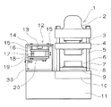
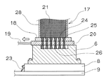
図1は、本発明の材料供給装置を圧縮成形機とともに示す正面図である。図2ないし図5は、本発明の材料供給方法を固定金型とともに工程順に示す縦断面図である。図6は、金型へ供給した材料を圧縮成形する状況を示す金型の縦断面図である。
Embodiments of the present invention will be described in detail with reference to the drawings.
FIG. 1 is a front view showing a material supply apparatus of the present invention together with a compression molding machine. 2 to 5 are longitudinal sectional views showing the material supply method of the present invention together with a fixed mold in the order of steps. FIG. 6 is a vertical cross-sectional view of the mold showing a situation where the material supplied to the mold is compression molded.
図1に示すように、圧縮成形機1は、ラム3を往復動可能に嵌挿し可動盤4を上下駆動する油圧シリンダ2と、可動金型5を取付ける可動盤4と、摺動盤8と案内板9を介して固定金型6を取付ける固定盤10と、固定盤10と油圧シリンダ2の鍔部との間に張設され可動盤4を案内するタイバ7とからなる。可動金型5と固定金型6とで金型が構成される。固定盤10は架台11の上面に固着され、固定盤10の上面に固定された案内板9は、固定盤10の上面と同一高さになるよう圧縮成形機1の外方まで設けられた架台11の上面に延設されている。固定金型6を取付けた摺動盤8は、固定金型6を可動金型5と型合わせされる位置と、圧縮成形機1の外方に設けた材料供給装置12の所定位置との間を、固定金型6がタイバ7の間を抜けて往復移動するように、案内板9上を案内されて移動する。なお、圧縮成形機1の油圧シリンダ2とラム3は、他の駆動手段例えばトグル機構やサーボモータとボールネジ等からなる公知のものに置換えてもよい。
As shown in FIG. 1, a compression molding machine 1 includes a
材料供給装置12は、架台11の上面に固着した支持枠14と、支持枠14の上部辺に垂設した複数の案内棒15と、案内棒15に案内されて上下する上板16と、案内棒15に案内されて上下しホッパ17の下面を形成する下板18と、上板16と下板18に挟持され下板18とともにホッパ17を形成する筒状体28と、下板18の下面を横駆動手段19により摺動するように設けられたシャッタ20と、上板16の上面に固着されホッパ17とシャッタ20を一体にして上下に移動させる縦駆動手段13とからなる。縦駆動手段13は、エアシリンダ等からなる。
The
圧縮成形機1は、図6に示すような圧縮成形を行い、成形品29が取出された後、可動金型5は固定金型6から上方に離隔し、図1に示す状態となる。その後、固定金型6は摺動盤8により材料供給装置12の下部の所定位置に移動する。この所定位置とは、固定金型6の上面に設けられたキャビティ凹部22がホッパ17の下面に全面で対向するときであり、摺動盤8の端面が案内板9の端部上面に設けた位置決部材30に当接して得られる。また、位置決部材30は案内板9の他の端部上面にも設けられ、固定金型6が可動金型5と型合わせ可能な位置が求められる。
The compression molding machine 1 performs compression molding as shown in FIG. 6, and after the molded
ホッパ17は、その横断面形状がキャビティ凹部22の形状と略同一かまたはわずかに小さい形状の筒状容器である。ホッパ17の下面を形成する下板18には複数の供給穴24が設けられている。供給穴24は、下方に向けて横断面積が漸次減少するように形成されている。供給穴24の配置は、供給穴24の下面開口部のシャッタ20の移動方向に隣り合う間隙が、供給穴24の下面開口部におけるシャッタ20の移動方向の長さより大きくなるように形成される。供給穴24の横断面形状は、丸、楕円、長円または多角形であり、その分布はキャビティ凹部22の内部に収まるように、シャッタ20の移動方向において等間隔に均一に形成される。なお、供給穴24の分布を、キャビティ凹部22の外周部において疎となるか外周縁部には分布しないようにすることにより、材料21のキャビティ凹部22への供給がキャビティ凹部22の外周部で減少させることができ、材料21の圧縮工程においてばりを減少させる等の効果を生む。
The
シャッタ20は、下板18の下面をエアシリンダ等からなる横駆動手段19によって摺動して移動する。シャッタ20は、下板18に設けた供給穴24と同位置に、供給穴24の下板18下面の開口部と同一形状の貫通穴25を有する。すなわちシャッタ20は、その全ての貫通穴25が下板18の全ての供給穴24と係合して貫通穴25と供給穴24が連通する位置と、その全ての貫通穴25が下板18の全ての供給穴24と係合せず非連通となる位置との間を往復移動する。
The
次に、図2ないし図5に基づいて材料供給装置12の作動と圧縮成形について説明する。圧縮成形に先立ち、ホッパ17内へ材料21を投入する。材料21は、粉末状であって、成形品29が燃料電池用セパレータであれば、黒鉛等の導電性フィラとフェノール樹脂等の熱硬化性樹脂との混合物である。なお、熱硬化性樹脂に代えて熱可塑性樹脂を用いることもある。材料21はホッパ17の中に数回の成形サイクルに要する分が貯留され、不足すれば別途の手段で適宜供給される。
Next, the operation and compression molding of the
まず、貫通穴25が供給穴24と非連通となるようにシャッタ20を位置決めし、摺動盤8を圧縮成形機1から外方へ搬送して材料供給装置12の下方に位置決めした後、縦駆動手段13を駆動してシャッタ20を固定金型6の上面に当接させる(図2)。
First, the
貫通穴25が供給穴24と連通となるようにシャッタ20を位置決めし、供給穴24と貫通穴25を通じてホッパ17の材料21をキャビティ凹部22へ供給する。この材料は第1供給材料26であり、材料21の特性に応じた斜面の山状にキャビティ凹部22の表面に堆積される(図3)。
The
次に、貫通穴25が供給穴24と非連通となるようにシャッタ20を再度位置決めし、貫通穴25内に残留していた材料21を第1供給材料26の間に第2供給材料27として落下させる(図4)。なお、第2供給材料27の量は、材料21の特性や成形品29の板厚に応じて調整する必要があり、そのためにシャッタ20は種々の板厚のものに容易に交換可能となっている。
Next, the
供給穴24と貫通穴25の間隔は、シャッタ20の移動方向とそれに直交する方向それぞれで等間隔になっているが、シャッタ20の移動方向に直交する方向の間隔を、シャッタ20の移動方向の間隔より狭くする。また、供給穴24と貫通穴25を、それらの長手方向がシャッタ20の移動方向に直交する長円や長方形である一の長孔とすれば、シャッタ20の移動方向に筋状に第2供給材料が供給されない部分が減少または生じないので、より均一な材料供給が行われる。このように、キャビティ凹部22の外周部を除く部分には、第1供給材料26と第2供給材料27がそれぞれの山の高さを略同一にして均一に堆積される。
The interval between the
縦駆動手段13を上に駆動して、シャッタ20を固定金型6の上面から離隔させる。この距離は約5mmであり、固定金型6が障害なく移動可能な最小の距離に設定される。そして、摺動盤8により固定金型6は圧縮成形機1の内部へ搬送される(図5)。なお、上記のように、材料供給装置12の下方に固定金型6が存在しなくなったとき、材料供給装置12から材料21の微粉等が案内板9上に落下し、摺動盤8の摺動の障害となることがある。そのような状況を回避するため、摺動盤8の移動方向端面には、摺動盤8の移動により前記微粉等を除去するスクレーパ23が設けられている。
The vertical drive means 13 is driven upward to separate the
圧縮成形機1に搬送された固定金型6は、可動金型5と型合わせ可能な位置に位置決めされる。可動盤4が下降し、可動金型5の凸部が固定金型6のキャビティ凹部22に嵌挿され、キャビティ凹部22の第1供給材料26と第2供給材料27は圧縮されて成形品29が成形される(図6)。
The fixed
なお、本発明は、当業者の知識に基づいて様々な変更、修正、改良等を加えた態様において実施され得るものを含む。また、前記変更等を加えた実施態様が、本発明の趣旨を逸脱しない限りいずれも本発明の範囲内に含まれるものであることは言うまでもない。例えば、材料供給装置を圧縮成形機の外方に配置せず、材料供給装置を圧縮成形機の開いた金型の間に進入させるように構成してもよい。 In addition, this invention includes what can be implemented in the aspect which added various change, correction, improvement, etc. based on the knowledge of those skilled in the art. Further, it goes without saying that any of the embodiments to which the above-mentioned changes are added is included in the scope of the present invention without departing from the gist of the present invention. For example, the material supply device may not be arranged outside the compression molding machine, and the material supply device may be inserted between the molds opened in the compression molding machine.
1 圧縮成形機
2 油圧シリンダ
3 ラム
4 可動盤
5 可動金型
6 固定金型
7 タイバ
8 摺動盤
9 案内板
10 固定盤
11 架台
12 材料供給装置
13 縦駆動手段
14 支持枠
15 案内棒
16 上板
17 ホッパ
18 下板
19 横駆動手段
20 シャッタ
21 材料
22 キャビティ凹部
23 スクレーパ
24 供給穴
25 貫通穴
26 第1供給材料
27 第2供給材料
28 筒状体
29 成形品
30 位置決部材
DESCRIPTION OF SYMBOLS 1
Claims (3)
下面に複数の供給穴を有するホッパと、前記供給穴と係合して連通と非連通を選択出現させる貫通穴を有し前記ホッパの下面を横駆動手段により摺動して移動するシャッタと、前記ホッパおよび前記シャッタを一体にして上下に移動させる縦駆動手段とを備えたことを特徴とする材料供給装置。 A material supply device for supplying powdered material to a mold of a compression molding machine,
A hopper having a plurality of supply holes on the lower surface, and a shutter that has a through hole that engages with the supply hole and selectively appears in communication and non-communication, and slides and moves on the lower surface of the hopper by lateral drive means; A material supply apparatus comprising: a vertical drive unit that moves the hopper and the shutter together to move up and down.
Priority Applications (1)
| Application Number | Priority Date | Filing Date | Title |
|---|---|---|---|
| JP2003353362A JP2005118786A (en) | 2003-10-14 | 2003-10-14 | Material feeding device and material feeding method in compression molding machine |
Applications Claiming Priority (1)
| Application Number | Priority Date | Filing Date | Title |
|---|---|---|---|
| JP2003353362A JP2005118786A (en) | 2003-10-14 | 2003-10-14 | Material feeding device and material feeding method in compression molding machine |
Publications (1)
| Publication Number | Publication Date |
|---|---|
| JP2005118786A true JP2005118786A (en) | 2005-05-12 |
Family
ID=34611664
Family Applications (1)
| Application Number | Title | Priority Date | Filing Date |
|---|---|---|---|
| JP2003353362A Pending JP2005118786A (en) | 2003-10-14 | 2003-10-14 | Material feeding device and material feeding method in compression molding machine |
Country Status (1)
| Country | Link |
|---|---|
| JP (1) | JP2005118786A (en) |
Cited By (9)
| Publication number | Priority date | Publication date | Assignee | Title |
|---|---|---|---|---|
| JP2009006374A (en) * | 2007-06-28 | 2009-01-15 | Kobe Steel Ltd | Compacting method of large-sized high-density green compact |
| JP2013039693A (en) * | 2011-08-12 | 2013-02-28 | Apic Yamada Corp | Resin supplying device, resin molding device, and resin supplying method |
| JP6017634B1 (en) * | 2015-06-10 | 2016-11-02 | Towa株式会社 | Resin material supply device and method for compression molding apparatus, compression molding apparatus, and resin molded product manufacturing method |
| JP2016190393A (en) * | 2015-03-31 | 2016-11-10 | Towa株式会社 | Resin material supply method and supply device for compression molding apparatus, compression molding method and compression molding apparatus |
| JP6039750B1 (en) * | 2015-06-10 | 2016-12-07 | Towa株式会社 | Resin material supply device and compression molding device for compression molding device |
| JP2016221576A (en) * | 2015-06-03 | 2016-12-28 | 株式会社デンソー | Powder feeding device, and powder feeding method using the powder feeding device |
| JP2018089916A (en) * | 2016-12-07 | 2018-06-14 | Towa株式会社 | Resin material supply apparatus and method for compression molding apparatus, and compression molding apparatus and resin molded product manufacturing method |
| CN110356038A (en) * | 2019-08-20 | 2019-10-22 | 长沙市晨来新材料科技有限公司 | A kind of molding fireworks delivery sheet |
| CN113306192A (en) * | 2021-05-22 | 2021-08-27 | 胡克雷 | High-efficient chemical industry pharmacy device |
-
2003
- 2003-10-14 JP JP2003353362A patent/JP2005118786A/en active Pending
Cited By (14)
| Publication number | Priority date | Publication date | Assignee | Title |
|---|---|---|---|---|
| JP2009006374A (en) * | 2007-06-28 | 2009-01-15 | Kobe Steel Ltd | Compacting method of large-sized high-density green compact |
| JP2013039693A (en) * | 2011-08-12 | 2013-02-28 | Apic Yamada Corp | Resin supplying device, resin molding device, and resin supplying method |
| KR101787234B1 (en) | 2015-03-31 | 2017-10-18 | 토와 가부시기가이샤 | Method and apparatus for supplying resin material of compression molding apparatus, compression molding method and compression molding apparatus |
| JP2016190393A (en) * | 2015-03-31 | 2016-11-10 | Towa株式会社 | Resin material supply method and supply device for compression molding apparatus, compression molding method and compression molding apparatus |
| JP2016221576A (en) * | 2015-06-03 | 2016-12-28 | 株式会社デンソー | Powder feeding device, and powder feeding method using the powder feeding device |
| JP6039750B1 (en) * | 2015-06-10 | 2016-12-07 | Towa株式会社 | Resin material supply device and compression molding device for compression molding device |
| JP6017634B1 (en) * | 2015-06-10 | 2016-11-02 | Towa株式会社 | Resin material supply device and method for compression molding apparatus, compression molding apparatus, and resin molded product manufacturing method |
| TWI608580B (en) * | 2015-06-10 | 2017-12-11 | 東和股份有限公司 | Resin material supply device and method for compression molding device, and compression molding device and method |
| KR101841831B1 (en) | 2015-06-10 | 2018-03-23 | 토와 가부시기가이샤 | Apparatus and method for supplying resin material of compression molding apparatus, compression molding apparatus and compression molding method |
| JP2018089916A (en) * | 2016-12-07 | 2018-06-14 | Towa株式会社 | Resin material supply apparatus and method for compression molding apparatus, and compression molding apparatus and resin molded product manufacturing method |
| KR20180065898A (en) * | 2016-12-07 | 2018-06-18 | 토와 가부시기가이샤 | Apparatus and method for supplying resin material of compression molding apparatus, compression molding apparatus and resin molding product manufacturing method |
| KR102114804B1 (en) | 2016-12-07 | 2020-05-25 | 토와 가부시기가이샤 | Apparatus and method for supplying resin material of compression molding apparatus, compression molding apparatus and resin molding product manufacturing method |
| CN110356038A (en) * | 2019-08-20 | 2019-10-22 | 长沙市晨来新材料科技有限公司 | A kind of molding fireworks delivery sheet |
| CN113306192A (en) * | 2021-05-22 | 2021-08-27 | 胡克雷 | High-efficient chemical industry pharmacy device |
Similar Documents
| Publication | Publication Date | Title |
|---|---|---|
| CN106955997B (en) | Full-automatic powder forming hydraulic machine | |
| CN206106278U (en) | Ejection mechanism and injection mold | |
| KR20190098786A (en) | liquid cartridge replaceable 3D printer | |
| CN116061381B (en) | Stamping type injection mold | |
| CN114823119B (en) | Forming device and forming method of E-shaped magnetic core | |
| CN104816501A (en) | Solid carbon dioxide forming machine and control method thereof | |
| JP2006103136A (en) | Sheet press | |
| JP2004277047A (en) | Powder supply device | |
| CN222571699U (en) | Quantitative powder feeding mechanism of powder forming machine and powder forming machine | |
| CN104162926B (en) | Brick making machine | |
| JP3602737B2 (en) | Powder mold | |
| CN210820137U (en) | Portable cloth pressed compact device | |
| CN102233637B (en) | Plastic mixture mold pressing machine translation blanking mechanism | |
| CN206122494U (en) | Towards type time delay mould of unloading | |
| JP2002153994A (en) | Powder molding press, and method for feeding molding powder | |
| CN205238899U (en) | Numerical control lock body roll extrusion trade mark machine | |
| JP2005035171A (en) | Form apparatus for concrete block | |
| CN108214827A (en) | A kind of bilayer clamp dog forcing press | |
| KR101442116B1 (en) | ejector for vertical insert injectoin molding machine | |
| CN109317676B (en) | Powder feeding device, powder feeding method and rapid forming equipment | |
| KR100278088B1 (en) | Method and apparatus for manufacturing prefabricated tile block | |
| US616401A (en) | callaway | |
| JP3677736B2 (en) | Material supply device in compression molding machine | |
| JP5347296B2 (en) | Powder molding apparatus and method for producing powder molded body | |
| CN222725465U (en) | A powder die casting machine |