JP2005069632A - Steam generator and heating cooker equipped with it - Google Patents
Steam generator and heating cooker equipped with it Download PDFInfo
- Publication number
- JP2005069632A JP2005069632A JP2003302936A JP2003302936A JP2005069632A JP 2005069632 A JP2005069632 A JP 2005069632A JP 2003302936 A JP2003302936 A JP 2003302936A JP 2003302936 A JP2003302936 A JP 2003302936A JP 2005069632 A JP2005069632 A JP 2005069632A
- Authority
- JP
- Japan
- Prior art keywords
- steam
- evaporation container
- steam generator
- splash
- water
- Prior art date
- Legal status (The legal status is an assumption and is not a legal conclusion. Google has not performed a legal analysis and makes no representation as to the accuracy of the status listed.)
- Pending
Links
Images

Abstract
Description
本発明は、蒸気により被加熱物の加熱、加湿を行う蒸気発生装置及びそれを備えた加熱調理器に関する。 The present invention relates to a steam generator for heating and humidifying an object to be heated with steam, and a cooking device provided with the steam generator.
蒸気発生装置の応用例として、水蒸気を用い食品等の被調理物の加熱、加湿を行う加熱調理器がよく知られている。この加熱調理器においては、蒸気発生装置にて、給水タンク等から供給された水で水蒸気を生成し、被調理物を収容した加熱室内に供給して、加熱調理を行う。加熱室内の温度が、被調理物に応じた所定の温度になり、被調理物に適した加熱時間が経過すると、水蒸気の供給が停止され、調理が完了する。 As an application example of a steam generator, a heating cooker that uses steam to heat and humidify an object to be cooked such as food is well known. In this heating cooker, steam is generated by water supplied from a water supply tank or the like by a steam generator, and supplied to a heating chamber containing an object to be cooked to perform cooking. When the temperature in the heating chamber reaches a predetermined temperature corresponding to the object to be cooked and the heating time suitable for the object to be cooked has elapsed, the supply of water vapor is stopped and cooking is completed.
水蒸気を使用することにより、被調理物内の水分の蒸発を防止して、しっとりとした仕上りに調理することが可能である。また、水蒸気は加熱室内を低酸素状態にすることが可能であり、被調理物の酸化を低減することが可能である。特許文献1には、従来の水蒸気を使用した加熱調理器の構造について、水蒸気を加熱室内に直接供給するものが記載されている。
このような蒸気発生装置では、激しい沸騰に伴い貯留水が飛散し、蒸気導出口の辺りにまで付着する。加熱終了後にその付着水が蒸発することで、そこにスケールが生成、堆積する。繰り返し使用することによってそのスケールが成長し、ついには蒸気導出口を塞いでしまう。このスケールが効率のよい蒸気の噴出を妨げたり、完全にふさがった場合には、蒸気発生装置としての機能を十分に発揮することができない状態となる。 In such a steam generator, stored water scatters with intense boiling and adheres to the vicinity of the steam outlet. When the adhering water evaporates after the heating is completed, scale is generated and deposited there. The scale grows by repeated use, and eventually the steam outlet is blocked. If this scale hinders efficient steam ejection or is completely blocked, the function as a steam generator cannot be fully exhibited.
本発明は、上記の点に鑑みなされたものであり、蒸気導出口付近に飛散する貯留水をなくすことによって、そこにスケールが付着、堆積することを防止し、蒸気発生機能の低下、停止を防ぐことを目的とする。 The present invention has been made in view of the above points, and by eliminating the stored water that scatters in the vicinity of the steam outlet, it prevents the scale from adhering and accumulating, thereby reducing and stopping the steam generation function. The purpose is to prevent.
上記目的を達成するために、本発明は、筒状の蒸発容器と、該蒸発容器の外側に設けた加熱源と、前記蒸発容器の上部に設けた蒸気導出口とを備えた蒸気発生装置において、蒸気発生時に発生する貯留水の飛沫を抑止する飛沫抑止手段を前記蒸発容器の内側に施したことを特徴とする。 In order to achieve the above object, the present invention provides a steam generator including a cylindrical evaporation container, a heating source provided outside the evaporation container, and a steam outlet provided in an upper part of the evaporation container. In addition, the present invention is characterized in that splash preventing means for suppressing the splash of stored water generated when steam is generated is provided inside the evaporation container.
この構成によれば、貯留水が蒸気導出口にまで到達することを防止し、スケールの付着、生成を抑止できる。 According to this configuration, it is possible to prevent the stored water from reaching the steam outlet, and to suppress the adhesion and generation of the scale.
上記飛沫抑止手段の具体例としては、蒸発容器の内面にテフロン、フッ素又は、シリコンの撥水処理を施すことが挙げられる。 As a specific example of the splash preventing means, water repellent treatment of Teflon, fluorine, or silicon is given to the inner surface of the evaporation container.
この構成によれば、蒸発容器内の加熱源付近から沸騰する際に発生する気泡が小さくなり、沸騰面より上に到達してはじける際に貯留水の飛沫を最小限に抑えることができ、蒸気導出口への到達を防ぐことができる。 According to this configuration, bubbles generated when boiling from the vicinity of the heating source in the evaporation container are reduced, and splashes of stored water can be minimized when reaching and rising above the boiling surface. Reaching the outlet can be prevented.
その他の例として、蒸発容器内の沸騰面より下で、気泡の発生する加熱源から上の位置に飛沫抑止体を設けてもよい。 As another example, a splash preventing body may be provided below the boiling surface in the evaporation container and above the heating source where bubbles are generated.
この構成によれば、水が沸騰した際に発生する気泡が、水中に設置された飛沫抑止体によって細分化される。沸騰面より上に到達した気泡がはじける際、細分化されていることによって、それがなされていない気泡よりも貯留水の飛散を最小限に抑えることができ、蒸気導出口への到達を防ぐことができる。これによって導出口へのスケールの付着、堆積を防ぎ、蒸気発生装置の機能の低下、停止を防止できる。 According to this configuration, the bubbles generated when the water boils are subdivided by the splash suppressing body installed in the water. When bubbles that have reached the boiling surface pop up, they can be subdivided to minimize the scattering of stored water and prevent them from reaching the steam outlet than bubbles that do not. Can do. This prevents the scale from adhering and accumulating on the outlet, and prevents the steam generator from being degraded or stopped.
また、本発明は、蒸発容器内に沸騰時に発生する気泡による貯留水の飛沫を抑えるため、蒸発容器内の沸騰面より上で、蒸気導出口より下の位置に飛散抑止体を備えたことを特徴とする。 Further, the present invention is provided with a scattering restrainer at a position above the boiling surface in the evaporation container and below the steam outlet in order to suppress splashing of the stored water due to bubbles generated during boiling in the evaporation container. Features.
この構成によれば、水が沸騰した際に発生する気泡がはじけて貯留水が飛散する際に、飛散抑止体によって、飛散した貯留水は飛散抑止体に接触しそれ以上には飛散しない。これによって貯留水が蒸気導出口にまで到達することを防止し、スケールの付着、生成を抑止できる。 According to this configuration, when the stored water scatters due to the bubbles generated when the water is boiled, the scattered water is brought into contact with the scattering body and is not scattered further by the scattering body. As a result, the stored water can be prevented from reaching the steam outlet, and scale adhesion and generation can be suppressed.
また、本発明では、飛沫抑止体又は、飛散抑止体の開口形状を、気泡を細分化することのできる大きさの網目形状とした。 Moreover, in this invention, the opening shape of the splash suppression body or the scattering suppression body was made into the mesh shape of the magnitude | size which can subdivide a bubble.
この構成によれば、水面下に設けられた飛沫抑止体又は、水面上に設けられた飛散抑止体は、沸騰によって生じた気泡をより小さな気泡に効率よく細分化することができ、蒸気導出口へのスケールの付着、堆積を防ぐことによって蒸気発生装置の機能の低下、停止を防止できる。 According to this configuration, the splash preventing body provided below the water surface or the scattering restraining body provided on the water surface can efficiently subdivide the bubbles generated by boiling into smaller bubbles, and the vapor outlet port. By preventing the scale from adhering to and depositing on the surface, it is possible to prevent the function and stoppage of the steam generator.
また、本発明では、蒸発容器内に複数個の飛沫抑止体と飛散抑止体を設けたことを特徴とする。 Further, the present invention is characterized in that a plurality of splash suppression bodies and scattering suppression bodies are provided in the evaporation container.
この構成によれば、沸騰面より下に飛沫抑止体、沸騰面より上に飛散抑止体を設置した場合の効果を併せ持つことが可能となる。飛沫抑止体が沸騰面より下の気泡の細分化を行うことができ、さらに沸騰面より上に設けられた飛散抑止体により飛散した貯留水の飛沫を蒸気導出口への到達を防止でき、蒸気発生装置の機能低下、停止をより効果的に行うことが可能となる。 According to this structure, it becomes possible to have the effect in the case of installing a splash inhibiting body below the boiling surface and a splash inhibiting body above the boiling surface. The splash suppression body can subdivide the bubbles below the boiling surface, and the splash of the stored water can be prevented from reaching the steam outlet by the splash suppression body provided above the boiling surface. It is possible to more effectively reduce and stop the function of the generator.
また、本発明では、前記の複数個設置された飛沫抑止体又は飛散抑止体において、その開口形状を、気泡を細分化することのできる大きさの網目形状とした。 Moreover, in this invention, the opening shape was made into the mesh shape of the magnitude | size which can subdivide a bubble in the said splash prevention body or scattering prevention body installed in multiple numbers.
この構成によれば、飛沫抑止体又は飛散抑止体による蒸気発生効率の低下を最小限に抑えて、上記の貯留水飛散防止の効果を得ることが可能となる。 According to this configuration, it is possible to minimize the reduction in steam generation efficiency due to the splash suppression body or the splash suppression body, and to obtain the effect of preventing the stored water scattering.
本発明によれば、沸騰による貯留水の飛散を防止でき、蒸気導出口への到達を防げ、蒸気導出口において、貯留水が乾燥することによるスケールの付着、堆積を抑止することが可能となる。これによって蒸気導出口のスケールによる閉鎖を防ぎ、蒸気発生機能の低下、停止を防止できる。 According to the present invention, it is possible to prevent the stored water from scattering due to boiling, to prevent the water from reaching the steam outlet, and to prevent the scale from adhering and accumulating due to drying of the stored water at the steam outlet. . This prevents the steam outlet from being closed by the scale and prevents the steam generation function from being lowered or stopped.
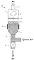
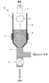
本発明の第1の実施形態について説明する。図1は、第1の実施形態に係る蒸気発生装置の概略断面図である。以下、蒸気発生装置10の構成と動作について説明する。
A first embodiment of the present invention will be described. FIG. 1 is a schematic cross-sectional view of a steam generator according to the first embodiment. Hereinafter, the configuration and operation of the
円筒形状の蒸発容器1の側壁外周に環状の加熱源2が配されている。この加熱源2はサーミスタなどの温度検知手段(図示せず)によって制御される。蒸発容器1の上部には蒸気導出口3が、下部には給排水口4が設けられている。蒸気導出口3の下には、円盤型の飛散抑止体5が固定されている。
An
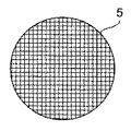
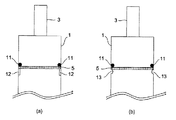
図2は、飛散抑止体の平面図である。飛散抑止体5は、ステンレスやセラミックスなどの耐腐食、耐熱性のある材質の網状体を、蒸発容器1の側壁内面形状に合わせて円盤状に成形加工して作成される。この飛散抑止体5の蒸発容器1への固定は、図3に符号11で示すように、溶接やロウ付け等により行う。なお、位置ずれ防止のために蒸発容器1の側壁内面にリブ12(同図(a)参照)や突起部13(同図(b)参照)などを設けておくとよい。
FIG. 2 is a plan view of the scattering suppression body. The
水7は給水タンク(図示せず)からポンプによって給排水口4を経て、少なくとも加熱源2の上端以上の水位まで貯留される。給水中、排水弁6は閉じられている。水位は別途水位センサー(図示せず)で制御される。その後、加熱源2によって加熱され、蒸発容器1内の水7は蒸気9となり、蒸発容器1内上部の空間で蒸気9のみが分離され蒸気導出口3から送り出される。
蒸発によって消費された水7は、水位センサーの検知手段によって適宜補給される。必要量の蒸気9を送り出した後、加熱終了し蒸発容器1内の水は給排水口4を経て手動、または自動による排水弁6の開放によって排出される。加熱された水7が沸騰し蒸気9を発生する際に、加熱源2近辺から気泡8を生じ、この気泡8が沸騰面においてはじけ、貯留水を飛散させる。
The
このとき、飛散抑止体5が存在することによって、飛散した貯留水は蒸気導出口3に達することなく、落下して再び貯留水として沸騰に供される。これによって、蒸気導出口3内にスケールが付着、堆積することなく、蒸気9の発生を効率よく行え、蒸気発生装置10の機能の低下、または停止を防止することができる。
At this time, due to the presence of the
本発明の第2の実施形態について説明する。図4は、第2の実施形態に係る蒸気発生装置の概略断面図である。上記第1の実施形態に係る蒸気発生装置と同一部材には同一符号を附している。同図に示すように、蒸発容器1の側壁内面には、水面より低くなる位置に飛沫抑止体14が固定されている。飛沫抑止体14は、上記飛散抑止体5と同一部材を使用し、同様の方法で固定される。
A second embodiment of the present invention will be described. FIG. 4 is a schematic cross-sectional view of a steam generator according to the second embodiment. The same members as those in the steam generator according to the first embodiment are denoted by the same reference numerals. As shown in the figure, the
この構成によると、発生する気泡が細分化され、沸騰面で破裂する気泡8が小さいものとなるので、貯留水の飛散が低減される。これによって、蒸気導出口3の内部へのスケールの付着、堆積を防止でき、効率のよい蒸気9の発生が行えるようになる。
According to this configuration, the generated bubbles are subdivided, and the
本発明の第3の実施形態について説明する。図5は、第3の実施形態に係る蒸気発生装置の概略断面図である。上記第1,第2の実施形態に係る蒸気発生装置と同一部材には同一符号を附している。同図に示すように、蒸発容器1の側壁内面には、飛散抑止体5及び飛沫抑止体14を複数平行に設けられている。
A third embodiment of the present invention will be described. FIG. 5 is a schematic cross-sectional view of a steam generator according to the third embodiment. The same members as those in the steam generators according to the first and second embodiments are denoted by the same reference numerals. As shown in the figure, a plurality of scattering
この構成によると、沸騰面の位置を考慮する必要なく、水中での気泡8の細分化、水面上方での貯留水の飛散防止を行うことができる。
According to this configuration, the
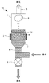
本発明の第4の実施形態について説明する。図6は、第4の実施形態に係る蒸気発生装置の概略断面図である。同図に示すように、蒸発容器1の内面に撥水処理15(テフロン、フッ素又は、シリコン)を施している。
A fourth embodiment of the present invention will be described. FIG. 6 is a schematic cross-sectional view of a steam generator according to the fourth embodiment. As shown in the figure, a water repellent treatment 15 (Teflon, fluorine or silicon) is applied to the inner surface of the
この構成によると、蒸発容器1内の加熱源2付近から沸騰する際に発生する気泡8が小さくなり、沸騰面より上に到達してはじける際に貯留水の飛沫を最小限に抑えることができ、蒸気導出口13への到達を防ぐ。
According to this configuration, the
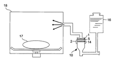
図7には、本発明に係る蒸気発生装置を備えた加熱調理器の構成について示している。給水タンク16から蒸気発生装置10に供給された水は、該蒸気発生装置10で水蒸気に生成され、被調理物17を収容する加熱室18へ供給され、被調理物17を加熱調理する構成になっている。
In FIG. 7, it has shown about the structure of the heating cooker provided with the steam generator which concerns on this invention. The water supplied from the
上記のように本発明の実施形態の例を示したが、この他、発明の主旨を逸脱しない範囲で種々の変更を加えて実施することができる。例えば、蒸発容器の形状を円筒以外のものとすることも可能である。 As described above, the example of the embodiment of the present invention has been described. However, various modifications can be made without departing from the spirit of the present invention. For example, the shape of the evaporation container may be other than a cylinder.
本発明の蒸気発生装置は、例えば、蒸気加熱式加熱調理器などへの応用が可能である。すなわち、水蒸気を加熱室へ供給し、被調理物を加熱調理する加熱調理器などに利用することができる。 The steam generator of the present invention can be applied to, for example, a steam heating type cooking device. That is, steam can be supplied to the heating chamber and used for a cooking device that cooks the food to be cooked.
1 蒸発容器
2 加熱源
3 蒸気導出口
4 給排水口
5 飛散抑止体
6 排水弁
10 蒸気発生装置
11 溶接部又はロウ付け部
14 飛沫抑止体
15 撥水処理
DESCRIPTION OF
Claims (6)
蒸気発生時に発生する貯留水の飛沫を抑止する飛沫抑止手段を前記蒸発容器の内側に施したことを特徴とする蒸気発生装置。 In a steam generator including a cylindrical evaporation container, a heating source provided outside the evaporation container, and a steam outlet provided in an upper part of the evaporation container,
A steam generating apparatus characterized in that splash control means for suppressing spray of stored water generated when steam is generated is provided inside the evaporation container.
蒸気発生時に発生した貯留水の飛沫が前記蒸気導出口に達するのを抑止する飛散抑止体を前記蒸発容器の内側に設けたことを特徴とする蒸気発生装置。 In a steam generator including a cylindrical evaporation container, a heating source provided outside the evaporation container, and a steam outlet provided in an upper part of the evaporation container,
A steam generating apparatus, comprising: a scattering suppression body that suppresses splashes of stored water generated when steam is generated from reaching the steam outlet.
Priority Applications (1)
| Application Number | Priority Date | Filing Date | Title |
|---|---|---|---|
| JP2003302936A JP2005069632A (en) | 2003-08-27 | 2003-08-27 | Steam generator and heating cooker equipped with it |
Applications Claiming Priority (1)
| Application Number | Priority Date | Filing Date | Title |
|---|---|---|---|
| JP2003302936A JP2005069632A (en) | 2003-08-27 | 2003-08-27 | Steam generator and heating cooker equipped with it |
Publications (2)
| Publication Number | Publication Date |
|---|---|
| JP2005069632A true JP2005069632A (en) | 2005-03-17 |
| JP2005069632A5 JP2005069632A5 (en) | 2006-05-25 |
Family
ID=34407069
Family Applications (1)
| Application Number | Title | Priority Date | Filing Date |
|---|---|---|---|
| JP2003302936A Pending JP2005069632A (en) | 2003-08-27 | 2003-08-27 | Steam generator and heating cooker equipped with it |
Country Status (1)
| Country | Link |
|---|---|
| JP (1) | JP2005069632A (en) |
Cited By (5)
| Publication number | Priority date | Publication date | Assignee | Title |
|---|---|---|---|---|
| JP2009527716A (en) * | 2006-02-16 | 2009-07-30 | アドバンスド エナジー インダストリーズ, インコーポレイテッド | System and method for delivering steam |
| JP2010121803A (en) * | 2008-11-17 | 2010-06-03 | Hoshizaki Electric Co Ltd | Steam generating device |
| JP2014529721A (en) * | 2011-09-02 | 2014-11-13 | ユーロプロ・オペレイティング・エルエルシー | Steam generator |
| CN104930488A (en) * | 2015-07-17 | 2015-09-23 | 东莞市菲腾电子科技有限公司 | Equipment with steam generation device and capable of rapidly stopping steam spraying outside |
| JP2021055988A (en) * | 2019-09-26 | 2021-04-08 | 攀▲鋼▼集▲団▼攀枝花▲鋼▼▲鉄▼研究院有限公司 | Raw coke oven gas sensible heat exchanger and mounting structure thereof |
-
2003
- 2003-08-27 JP JP2003302936A patent/JP2005069632A/en active Pending
Cited By (6)
| Publication number | Priority date | Publication date | Assignee | Title |
|---|---|---|---|---|
| JP2009527716A (en) * | 2006-02-16 | 2009-07-30 | アドバンスド エナジー インダストリーズ, インコーポレイテッド | System and method for delivering steam |
| JP2010121803A (en) * | 2008-11-17 | 2010-06-03 | Hoshizaki Electric Co Ltd | Steam generating device |
| JP2014529721A (en) * | 2011-09-02 | 2014-11-13 | ユーロプロ・オペレイティング・エルエルシー | Steam generator |
| US9964299B2 (en) | 2011-09-02 | 2018-05-08 | Sharkninja Operating Llc | Steam generator |
| CN104930488A (en) * | 2015-07-17 | 2015-09-23 | 东莞市菲腾电子科技有限公司 | Equipment with steam generation device and capable of rapidly stopping steam spraying outside |
| JP2021055988A (en) * | 2019-09-26 | 2021-04-08 | 攀▲鋼▼集▲団▼攀枝花▲鋼▼▲鉄▼研究院有限公司 | Raw coke oven gas sensible heat exchanger and mounting structure thereof |
Similar Documents
| Publication | Publication Date | Title |
|---|---|---|
| RU2674295C2 (en) | Device for generating steam | |
| JP4934657B2 (en) | Cooker | |
| RU2531415C2 (en) | Cooking device | |
| KR20190092571A (en) | Modular steamer accessories for steam-heating and / or steam-cooking food contained in containers | |
| JP2007232270A (en) | Cooker | |
| JP2005083740A (en) | Superheated steam cooker | |
| JP2005069632A (en) | Steam generator and heating cooker equipped with it | |
| JP4187613B2 (en) | Steam generator and cooking device equipped with the same | |
| JP2005069632A5 (en) | ||
| KR102316020B1 (en) | Steam Generator for Steaming Food | |
| KR20110106719A (en) | Heating apparatus using water vapour bubble and method of using the same | |
| JP4934706B2 (en) | Induction heating cooker | |
| KR20120109454A (en) | Heating apparatus using water vapour bubble and method of using the same | |
| JP2012122675A (en) | Heating cooker | |
| JP2010032120A (en) | Steam generator and heating cooker | |
| JP4186821B2 (en) | rice cooker | |
| JP2019195416A (en) | Cooking ingredient boiling machine | |
| JP4029892B2 (en) | rice cooker | |
| JP2006280205A (en) | Oven with steam generator | |
| JP6651292B2 (en) | Cooking device | |
| JP5180057B2 (en) | Heating equipment | |
| JP2010038407A (en) | Steam generator and heating cooker | |
| JP2674200B2 (en) | Steam generator | |
| JP5318488B2 (en) | Steam generator and cooking device | |
| KR20170003266U (en) | Noise reducer for pressure rice cooker |
Legal Events
| Date | Code | Title | Description |
|---|---|---|---|
| A621 | Written request for application examination |
Free format text: JAPANESE INTERMEDIATE CODE: A621 Effective date: 20050810 |
|
| A521 | Written amendment |
Free format text: JAPANESE INTERMEDIATE CODE: A523 Effective date: 20060404 |
|
| A131 | Notification of reasons for refusal |
Free format text: JAPANESE INTERMEDIATE CODE: A131 Effective date: 20070717 |
|
| RD01 | Notification of change of attorney |
Free format text: JAPANESE INTERMEDIATE CODE: A7421 Effective date: 20070903 |
|
| A521 | Written amendment |
Free format text: JAPANESE INTERMEDIATE CODE: A523 Effective date: 20070918 |
|
| A131 | Notification of reasons for refusal |
Free format text: JAPANESE INTERMEDIATE CODE: A131 Effective date: 20071030 |
|
| A02 | Decision of refusal |
Free format text: JAPANESE INTERMEDIATE CODE: A02 Effective date: 20080304 |