JP2004532441A - System and method for extracting predetermined points of an object in front of a computer-controllable display captured by an imaging device - Google Patents
System and method for extracting predetermined points of an object in front of a computer-controllable display captured by an imaging device Download PDFInfo
- Publication number
- JP2004532441A JP2004532441A JP2002561766A JP2002561766A JP2004532441A JP 2004532441 A JP2004532441 A JP 2004532441A JP 2002561766 A JP2002561766 A JP 2002561766A JP 2002561766 A JP2002561766 A JP 2002561766A JP 2004532441 A JP2004532441 A JP 2004532441A
- Authority
- JP
- Japan
- Prior art keywords
- pixel
- display area
- pixels
- image
- identifying
- Prior art date
- Legal status (The legal status is an assumption and is not a legal conclusion. Google has not performed a legal analysis and makes no representation as to the accuracy of the status listed.)
- Pending
Links
Images


Classifications
-
- G—PHYSICS
- G06—COMPUTING; CALCULATING OR COUNTING
- G06T—IMAGE DATA PROCESSING OR GENERATION, IN GENERAL
- G06T1/00—General purpose image data processing
- G06T1/0007—Image acquisition
Abstract
画像取り込み装置によって取り込まれるコンピュータ制御表示エリアの前にある物体の所定点を識別するシステムおよび方法は、画像取り込み装置(13)の取り込みエリア(10C)内の表示エリア(10B)の画像を取り込む(20)ことによって実施される。表示エリア内の物体と、取り込みエリア内の表示エリアの周囲境界と、に対応する、取り込みデータ内の画素が識別される(21、22)。物体画素および周囲境界画素の共通のサブセットに対応する画素が識別および格納される(23)。探索は、共通の画素および物体画素を用いて実施され、取り込みエリア内の表示エリアにおける物体の所定点に対応する画素を決定する。
【選択図】図1A system and method for identifying a predetermined point on an object in front of a computer controlled display area captured by an image capture device captures an image of a display area (10B) within a capture area (10C) of an image capture device (13). 20). Pixels in the captured data corresponding to the object in the display area and the boundary of the display area in the capture area are identified (21, 22). Pixels corresponding to a common subset of object pixels and surrounding boundary pixels are identified and stored (23). The search is performed using a common pixel and an object pixel to determine a pixel corresponding to a predetermined point of the object in the display area in the capture area.
[Selection diagram] Fig. 1
Description
【技術分野】
【0001】
本発明は、コンピュータ制御可能な表示システムに関し、特に、ユーザと、コンピュータ制御される表示画像との対話に関する。
【背景技術】
【0002】
コンピュータ制御投影システムは、一般に、画像データを生成するためのコンピュータシステムおよびその画像データを投影スクリーンに投影するためのプロジェクタを有する。通常、コンピュータ制御投影システムは、プレゼンタが、コンピュータシステムを用いて作成されたプレゼンテーションをより大きなスクリーンに投影し、一人より多くのビューアがそのプレゼンテーションを容易に見ることができるようにするために用いられる。大抵の場合、プレゼンタは、投影画像上の注目すべきエリアを指、レーザポインタまたは他のポインティング装置で指すことによって投影画像と対話する。
【0003】
このタイプのシステムにおける問題は、ユーザが投影画像を任意に変更したい場合に、マウス、キーボードまたはリモートデバイスなどの入力装置を用いてコンピュータシステム(投影画像ではない)と対話しなければならないことである。例えば、装置は、大抵の場合、赤外線信号を介してコンピュータシステムを遠隔制御し、プレゼンテーションにおける次のスライドを表示するためにプレゼンタによって用いられる。しかし、これは、プレゼンテーションのビューアの注意をそらす可能性がある。なぜなら、プレゼンタは、ビューアおよび投影されたプレゼンテーションともはや対話せず、その代わりに、コンピュータシステムと対話しているからである。大抵の場合、この対話は、プレゼンテーションにおいて著しい中断を引き起こし得る。
【0004】
したがって、コンピュータのみとの対話という問題を克服するために上記のシステムの変形形態が開発されており、それによってプレゼンタは、投影画像と直接対話することができるため、プレゼンタは視聴者とより良く対話することができる。このシステムでは、コンピュータシステムは、画像プロジェクタで投影スクリーン上に投影される画像データ(例えば、プレゼンテーションスライド)を生成する。システムはまた、投影画像を取り込むためにディジタルカメラなどのディジタル画像取り込み装置を有する。取り込まれた投影画像データは、コンピューティングシステムに再び送信され、スクリーンの前の任意の物体(たとえば、ポインティング装置)の位置を決定するために用いられる。次に、コンピュータシステムは、ポインティング装置の決定された位置に応じて制御され得る。例えば、本願の譲受人に譲渡された米国特許第5,138,304号では、光ビームは、スクリーンに投影され、カメラで検出される。光ビームの位置を決定するために、投影画像の取り込まれた画像データおよび元の画像データは、比較され、ポインタ位置が決定される。次に、コンピュータは、ポインタ位置にビデオ画像内のカーソルを位置決めするか、ポインタ位置に応答して投影画像を変更するようになされる。
【0005】
ユーザ対話式コンピュータ制御表示または投影システムを実施するために、まず、取り込み画像データ内の表示または投影画像の位置を識別し、表示または投影画像に対応する取り込みデータを分析して画像の前にある物体を識別し、その位置を検出することが必要である。次に、物体位置検出情報は、物体の位置に応答するためにコンピュータシステムによって用いられ、プレゼンタによって所望されるように表示または投影画像を変更する。
【0006】
このタイプのシステムでは、システムがさらに物体の所定点を識別し、その位置を検出することができることも望まれる。例えば、ポインタの所定点は、ポインタの先端またはプレゼンタの指の先端であり得る。したがって、プレゼンタは、表示画像内の特定の位置を正確に指し、システムに所定点の特定の位置に従って応答させる。
【0007】
従来、ディスプレイの前にある物体の所定点の識別および位置の検出は、徹底的な数学的操作を必要とする取り込み画像データの詳細な画像分析を行うことによって成し遂げられていた。
【0008】
したがって、リアルタイム動作中に実施されるのに十分簡単なユーザ対話式コンピュータ制御表示システムにおいて、表示または投影画像の前にある物体の所定点の位置を検出する技法が求められている。
【発明の開示】
【0009】
画像取り込み装置によって取り込まれたコンピュータ制御表示エリアの前にある物体の所定点を識別するシステムおよび方法が記載される。このシステムおよび方法によると、取り込み表示エリアまで延在する物体の所定点は、境界までの取り込み表示エリアデータの隣接画素の最短経路を有する、表示エリアの周辺境界から最も遠くにある物体の点である。
【0010】
本方法の1つの実施形態は、表示エリアの画像を取り込んで、取り込みデータを得ることと、取り込みデータ内の物体に対応する、取り込みデータ内の画素を識別することと、取り込みデータ内の表示エリアの周囲境界に対応する、取り込みデータ内の画素を識別することと、物体画素および周囲境界画素に共通の画素のサブセットを識別および格納することと、次に、共通画素および物体画素を用いて探索を行い、物体の所定点に対応する画素の位置を検出することと、によって実行される。1つの実施形態では、探索は、幅優先探索アルゴリズムを用いて実施される。
【0011】
画像取り込み装置によって取り込まれるコンピュータ制御表示エリアの前にある物体の所定点を識別するためのシステムの1つの実施形態は、画像データに応答して、表示エリア内に少なくとも1つの画像を表示するためのコンピューティングシステムと、取り込みエリア内の表示エリアを含む画像データを取り込むための画像取り込み装置と、表示エリアにおける物体に対応する、取り込みデータにおける画素を識別する手段と、表示エリアの周囲境界に対応する、取り込みデータ内の画素を識別するための手段と、物体画素および境界画素に共通な画素のサブセットを識別および格納するための手段と、表示エリア内の物体の所定点に対応する画素を決定するための共通画素および物体画素を探索するための手段とを有する。1つの実施形態では、探索するための手段は、ソフトウェア、ハードウェア、またはソフトウェアとハードウェアとの組み合わせの1つにおいて実施可能な幅優先探索アルゴリズムを含む。
【0012】
本発明の目的、特徴、および利点は、以下の詳細な説明を考慮することにより、当業者に明白となる。
【0013】
発明の詳細な説明
画像取り込み装置によって取り込まれるコンピュータ制御表示エリアの前にある物体の所定点を識別するシステムおよび方法。システムおよび方法によると、取り込み表示エリアまで延在する物体の所定点は、境界までの隣接画素の最短経路を有する、表示エリアの周囲境界からの距離が最も遠い物体の点である。このように所定点を定義することにより、物体の所定点を見つけるための簡単で低度の計算探索アルゴリズムを用いることが容易になり、リアルタイム表示プレゼンテーションに適用可能なシステムおよび方法を提供することができる。
【0014】
画像データ10Aを生成するためのコンピューティングシステム10および画像データ10Aに対応する画像10Bを表示エリア12に表示するためのグラフィカルインターフェース11を含む物体の所定点を識別するシステムの1つの実施形態が、ブロック図(図1)に示される。グラフィカルインターフェースは、コンピューティングシステムの一部であるか、またはコンピューティングシステムの外部にある別個の素子であり得ることを理解されたい。システムはさらに、表示画像10Bを取り込むための関連の画像取り込みエリア13Aを有する画像取り込み装置13を有する。取り込み画像はまた、表示画像10Bの外側にある物体または領域の画像10Cを含む。取り込み画像はまた、表示エリア12の前の画像取り込みエリア13A内に位置する物体10Dを含み得る。取り込み画像は、ディジタル画像データ13Bに変換され、所定点ロケータ14に送信される。所定点ロケータ14は、境界画素識別手段15、物体画素識別手段16、共通の物体および境界画素識別手段17、および所定点サーチャ18を含む。
【0015】
境界画素識別手段15は、取り込み画像データ13Bを受信し、表示エリア12の周囲境界に対応するデータ13B内の画素のサブセット15Aを識別する。本発明の1つの実施形態によると、周囲境界画素は、本明細書において参考にために援用した米国特許出願第09/774,452号に記載されるシステムおよび方法を用いて決定される。この技法によると、表示エリアの周囲境界は、複数の表示および取り込み画像に対応する画像データから建設的および破壊的フィードバックデータを引き出すことによって識別される。1つの実施形態では、境界画素識別手段15は、リアルタイムプレゼンテーションの使用前に図1に示されるシステムを較正している間に用いられる。
【0016】
物体画素識別手段16は、取り込み画像データ13Bを受信し、表示エリア12の前景に位置する物体の一部分10E(物体10Dの暗くなった部分)に対応する、データ13Bにおける画素のサブセット16Aを識別する。本発明の1つの実施形態によると、物体画素は、本明細書に参考のために援用した米国特許出願第09/775,032号に記載されるシステムおよび方法を用いて決定される。この技法によると、物体画素は、まず、システムを較正し、表示エリアと、画像取り込み装置の取り込みエリアにおける取り込み表示エリアとの間の座標位置マッピング関数および輝度マッピング関数を得ることによって識別される。一旦較正されると、a)マッピング関数を用いて表示エリア画像データを変換し、予想される取り込み表示エリアデータを得ること、b)表示エリア画像を取り込み、実際に取り込まれた表示エリアデータを得ること、およびc)予想データと実際のデータとを比較し、取り込みエリア内の表示エリアの前にある物体の位置を決定して、物体に対応する、取り込み画像データ13B内の画素を識別すること、によって、物体の位置がリアルタイムシステム動作中に検出され得る。
【0017】
共通の物体および境界画素識別手段17は、物体および境界画素(すなわち、サブセット15Aおよび16A)の両方に共通の画素のサブセット17Aを識別する。この識別が行われる1つの方法は、物体画素のサブセット16Aを境界画素のサブセット15Aと画素毎に比較することである。一旦サブセット17Aが識別されると、それは、先入れ/先出し格納エリア(FIFO)(図示せず)に格納される。FIFOは、所定点サーチャ18、コンピューティングシステム10の一部、または外部メモリユニットのうちの1つにおける格納エリアであり得ることを理解されたい。
【0018】
所定点サーチャ18は、格納された画素のサブセット17Aおよび物体画素のサブセット16Aを用いて探索を行い、物体の所定点に対応する物体画素値を決定する。1つの実施形態では、サーチャ18は、格納されたサブセット17Aを用いて物体画素のサブセット16Aを探索するための幅優先探索ユニットを含む。所定点位置検出情報18Aは、コンピューティングシステム10に送信され、ユーザ対話式コンピュータ制御表示システムにおいて用いられる。
【0019】
本実施形態では、コンピューティングシステム10は、少なくとも中央処理ユニット(CPU)およびディジタルデータ(例えば、画像データ)を格納するためのメモリを有し、少なくとも3つのレベルのグレイスケール画像を生成する能力を有する。表示エリアは、グラフィカルインターフェースによって駆動されるコンピュータモニタか、または投影スクリーン上のエリアもしくは投影エリア(例えば、壁)であり得る。画像が投影を用いて表示される場合、システムは、グラフィカルインターフェースから提供される画像データに応答する画像プロジェクタ(図1に図示せず)を含む。
【0020】
1つの実施形態では、画像取り込み装置は、既知の時間遅延内で表示エリア12に表示される画像10Bの少なくともすべてを取り込むように構成されたディジタルスチルまたはビデオカメラである。画像が、カメラの取り込みエリア内でセンサに入射する光の強度を検出するセンサのアレイを用いてディジタルカメラによって取り込まれることは、ディジタル画像取り込みの分野において既知である。次に、光強度信号は、取り込み画像に対応するディジタル画像データに変換される。このように、取り込み画像データ13Bは、取り込み画像に対応するディジタル画像データである。他の実施形態では、画像取り込み装置は、アナログスチルまたはビデオカメラであり、取り込みアナログ画像データは、取り込みディジタル画像データ13Bに変換される。
【0021】
1つの実施形態では、画像10Bは、ユーザのコンピュータ生成スライドプレゼンテーションにおける複数のスライドに対応する。
【0022】
所定点ロケータ14の機能のすべてまたは一部は、コンピューティングシステムによって実施され得ることを理解されたい。この結果、所定点ロケータ14のすべてまたは一部は、コンピューティングシステムの外部に図示されているが、コンピューティングシステム内で実施され得る。
【0023】
所定点ロケータ14は、ソフトウェア実施態様、ハードウェア実施態様、またはソフトウェア実施態様とハードウェア実施態様との任意の組み合わせで実施され得る。
【0024】
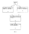
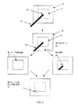
図2は、画像取り込み装置によって取り込まれる表示エリアの前景にある物体の所定点を識別するための方法の実施形態を示し、図3は、図2に示されるプロセスに関連する画像を例示する。図3を参照すると、取り込みエリア30は、表示エリア31を含む。表示エリア31は、コンピューティングシステム10によって生成される画像データ10Aにより表示される画像を含む。取り込みエリアおよび表示エリアには、所定点32を有する物体33が延在している。まず、画像が取り込まれる(ブロック20)。図3は、表示エリア31に表示される画像と、取り込みエリア30に延在する物体の一部分33Aと、表示エリアの外側であるが取り込みエリア内である領域と、に対応するデータを含む取り込み画像データ34を示す。
【0025】
次に、表示エリアの周囲境界のそれぞれに対応する(ブロック21)および表示エリアの前景にある物体に対応する(ブロック22)、取り込み画像データ内の画素のサブセットが識別される。図3は、物体画素のサブセット36および境界画素のサブセット35を示す。次に、物体および周囲境界画素値サブセットに共通の画素のサブセット(37、図3)が決定され、FIFOに格納される(ブロック23)。次に、共通画素のサブセットおよび物体画素のサブセットは、物体画素を探索するために用いられ、ディスプレイの前景における物体の所定点が見出される(ブロック24)。
【0026】
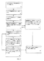
本発明のシステムおよび方法の1つの実施形態によると、共通画素と、物体画素のサブセットとは、ソフトウェア、ハードウェア、またはソフトウェアとハードウェアとの任意の組み合わせの1つにおいて実施され得る幅優先探索アルゴリズムを用いて探索される。幅優先探索アルゴリズムは、グラフを探索するために用いられる既知のアルゴリズムである。図4は、幅優先探索アルゴリズムを取り込み表示エリアに対応する画素のアレイに適用する例を示す。アレイは、表示エリアの前景にある物体に対応する画素(すなわち、B1、B2、B3、1〜9)、および表示エリアの周囲境界に対応する画素(x、B1、B2、B3で記される画素)を含む。図5は、図4に示される画素に対する幅優先探索を実施するためのプロセスを示し、図6は、図5に示される方法を実施する際に形成される図4に示すアレイに対応する例示的なFIFOを示す。
【0027】
まず、共通の物体および周囲境界画素(すなわち、B1、B2、B3)がFIFOに格納される(ブロック50)。FIFOに格納された各画素には、インジケータN=1が割り当てられる(ブロック51)。ここで、Nは、表示エリアの周囲境界までの画素の距離インジケータに対応する。したがって、FIFOにおける第1、第2および第3のエントリであるB1、B2およびB3(図6)には、N=1が割り当てられる。画素10および11は、図4に示されるアレイにおける物体画素として誤って現れるノイズに対応することに留意されたい。しかし、これらの画素は、境界画素ではなく、境界画素に対して垂直または水平方向に隣接していないため、FIFOには格納されず、図5に示されるプロセスに対して影響を与えない。
【0028】
FIFOにおける第1の画素エントリB1から開始し(ブロック52)、これに隣接する他の物体画素があるかどうかを決定する(ブロック53)。ここで、隣接画素は、検討対象の画素エントリに対して垂直または水平方向に隣接する画素として定義される。図4から理解できるように、B1に隣接する唯一の画素はB2である。各隣接画素は、FIFOにすでに格納されているかどうかを決定するためにチェックされる(ブロック54)。B2はFIFOにすでに格納されているため、次の画素エントリが処理される(ブロック55および56)。ブロック53〜55に記載されるプロセスは、第2のFIFOエントリB2に対して実施される。図4から理解できるように、B1、B3および画素1は、画素B2に隣接している。次に、FIFOに格納されていない検討対象の画素エントリ(p)に隣接する各画素(ap)については、FIFOに格納し、N(ap)=N(p)+1が割り当てられる(ブロック53〜55)。画素1はFIFOに格納されていない唯一の隣接画素であるため、格納され、Npixel1=NB2+1=1+1=2が割り当てられる。FIFOに格納されている所与の画素が、隣接の画素を有さない場合、次の画素エントリに進む(ブロック57)。図6に示されるFIFOを形成しながら、図5に示される物体画素の残りの処理を続行する。
【0029】
・第3エントリ、B3は、B2および画素2に隣接している。画素B2は、FIFOにすでに格納されており、画素2がFIFOに格納されて、Npixel2=NB3+1=1+1=2が割り当てられる。
・第4エントリ、画素1は、B2および画素2に隣接している。共にFIFOにすでに格納されており、次のエントリに進む。
・第5エントリ、画素2は、B3、画素1、3および4に隣接している。画素B3および1はすでに格納されているため、画素3および4が、FIFOに格納され、それぞれ、Npixel3=Npixel4=Npixel2+1=2+1=3が割り当てられる。
・第6エントリ、画素3は、画素2および5に隣接している。画素2は、すでに格納されているため、画素5が、FIFOに格納され、Npixel5=Npixel3+1=3+1=4が割り当てられる。
・第7エントリ、画素4は、画素2および5に隣接している。画素2および5は共に格納されているため、次のエントリに進む。
・第8エントリ、画素5は、画素3、4および6に隣接している。画素3および4は共にすでに格納されているため、画素6が、FIFOに格納され、Npixel6=Npixel5+1=4+1=5が割り当てられる。
・第9エントリ、画素6は、画素5、7および8に隣接している。画素5はすでに格納されているため、画素7および8が、FIFOに格納され、Npixel7=Npixel8=Npixel6+1=5+1=6が割り当てられる。
・第10エントリ、画素7は、画素6および9に隣接している。画素6はすでに格納されているため、画素9が、FIFOに格納され、Npixel9=Npixel7+1=6+1=7が割り当てられる。
・第11エントリ、画素8は、画素6および9に隣接している。画素6および9は、すでに格納されているため、次の画素に進む。
・第12エントリ、画素9は、画素7および8に隣接している。画素7および8は、すでに格納されており、これ以上の画素エントリはない。
【0030】
最も大きいNを有する画素(すなわち、画素9)は、所定点に対応する画素である(ブロック58)。
【0031】
幅優先探索アルゴリズムは、ダイナミックプログラミング探索アルゴリズムの簡単なバージョンであり、画素隣接性および画素距離の定義が様々である他のダイナミックプログラミング探索アルゴリズムなどの、物体の所定点の位置を検出するための他の探索アルゴリズムを用いてもよいことを理解されたい。
【0032】
図1から図6に示されるシステムおよび方法によると、表示画素の前にある非静的物体の移動および位置が常に決定されることにも留意されたい。したがって、表示スクリーンの周囲境界に対応する画素のサブセットが一旦決定されても、物体に対応する画素のサブセットは、リアルタイムプレゼンテーション中に物体の移動および位置を検出するために連続して決定される。例えば、画像取り込み装置13は、連続して表示エリアを取り込むことができ、新しく取り込まれた各画像に対応する画像データは、異なる時間間隔で物体画素のサブセットの位置を検出するために用いられる(図2、ブロック22)。この結果、各時間間隔における物体画素の所定点が決定され得る。幅優先探索アルゴリズムは、計算上簡単な探索技法であるため、所定点の決定は、リアルタイムで実施され得る。
【0033】
このように、画像取り込み装置によって取り込まれる表示エリアの前景における物体の所定点を見出すための簡略化されたリアルタイムシステムおよび方法について記載した。
【0034】
上記の説明では、本発明を完全に理解してもらうために多くの具体的な詳細を提示した。しかし、当業者には、これらの具体的な詳細は、本発明を実行するために用いられる必要はないことが明らかであろう。その他、本発明を不必要に不明瞭にするのを避けるため、既知の画像処理技法については詳細に記載していない。
【0035】
さらに、本発明の要素を特定の実施形態に関連して記載したが、本発明は、様々な他の方法で実施され得ることが理解される。この結果、例示として図示され記載される特定の実施形態は、限定するものとして見なされることを決して意図しないことが理解されるであろう。これらの実施形態の詳細を参照することは、本発明の本質と見なされる特徴のみを記載する特許請求項の範囲を限定することを意図するものではない。
【図面の簡単な説明】
【0036】
【図1】本発明による画像取り込み装置によって取り込まれるコンピュータ制御表示エリアの前にある物体の所定点を識別するためのシステムの第1の実施形態を示す図である。
【図2】本発明による画像取り込み装置によって取り込まれるコンピュータ制御表示エリアの前にある物体の所定点を識別する方法の第1の実施形態を示す図である。
【図3】本発明のシステムおよび方法に従った画素の識別を示す図である。
【図4】表示エリアの周囲境界および表示エリア内の物体を含む取り込み表示エリアを示す画素のアレイを示す図である。
【図5】図4に示す画素に対して幅優先探索を実施するための流れ図である。
【図6】図4に示すアレイに対して幅優先探索アルゴリズムを実施するときに形成される例示的なFIFOを示す図である。
【符号の説明】
【0037】
10:コンピューティングシステム
10B:画像データ10Aに対応する画像
10C:表示エリア10Bの外側にある物体または領域の画像
10D:物体
11:グラフィカルインターフェース
12:表示エリア
13:画像取り込み装置
13A:画像取り込みエリア
14:所定点ロケータ
15:境界画素識別手段
16:物体画素識別手段
17:共通の物体および境界画素識別手段
18:所定点サーチャ【Technical field】
[0001]
The present invention relates to computer-controllable display systems, and more particularly to the interaction of a user with a computer-controlled display image.
[Background Art]
[0002]
Computer controlled projection systems generally include a computer system for generating image data and a projector for projecting the image data onto a projection screen. Typically, computer-controlled projection systems are used by presenters to project presentations created using a computer system onto a larger screen so that more than one viewer can easily view the presentation. . In most cases, the presenter interacts with the projected image by pointing at an area of interest on the projected image with a finger, laser pointer, or other pointing device.
[0003]
The problem with this type of system is that if the user wishes to change the projected image at will, he must interact with the computer system (not the projected image) using an input device such as a mouse, keyboard or remote device. . For example, the device is often used by presenters to remotely control a computer system via infrared signals and to display the next slide in a presentation. However, this can distract the viewer of the presentation. This is because the presenter no longer interacts with the viewer and the projected presentation, but instead interacts with the computer system. In most cases, this interaction can cause a significant break in the presentation.
[0004]
Therefore, variants of the above system have been developed to overcome the problem of computer-only interaction, which allows the presenter to interact directly with the projected image so that the presenter can better interact with the viewer. can do. In this system, a computer system generates image data (eg, presentation slides) that is projected on a projection screen by an image projector. The system also has a digital image capture device, such as a digital camera, for capturing the projected image. The captured projection image data is transmitted again to the computing system and used to determine the position of any object (eg, pointing device) in front of the screen. Next, the computer system may be controlled in response to the determined position of the pointing device. For example, in US Pat. No. 5,138,304, assigned to the assignee of the present application, a light beam is projected onto a screen and detected by a camera. To determine the position of the light beam, the captured image data of the projected image and the original image data are compared to determine a pointer position. Next, the computer is adapted to position the cursor in the video image at the pointer position or change the projected image in response to the pointer position.
[0005]
To implement a user interactive computer controlled display or projection system, first identify the position of the display or projection image in the captured image data and analyze the captured data corresponding to the display or projection image to precede the image. It is necessary to identify an object and detect its position. The object location information is then used by the computer system to respond to the location of the object and modify the displayed or projected image as desired by the presenter.
[0006]
In this type of system, it is also desirable that the system be able to further identify a predetermined point on the object and detect its position. For example, the predetermined point of the pointer may be the tip of the pointer or the tip of the presenter's finger. Thus, the presenter points exactly to a particular location in the displayed image and causes the system to respond according to the particular location of the predetermined point.
[0007]
Traditionally, identification and location of a given point on an object in front of a display has been accomplished by performing a detailed image analysis of the captured image data that requires extensive mathematical manipulation.
[0008]
Therefore, what is needed is a technique for locating a predetermined point of an object in front of a displayed or projected image in a user-interactive computer-controlled display system that is simple enough to be implemented during real-time operation.
DISCLOSURE OF THE INVENTION
[0009]
A system and method for identifying a predetermined point on an object in front of a computer controlled display area captured by an image capture device is described. According to the system and method, the predetermined point of the object extending to the capture display area is the point of the object furthest from the peripheral boundary of the display area having the shortest path of the adjacent pixel of the capture display area data to the boundary. is there.
[0010]
One embodiment of the method includes capturing an image of a display area to obtain capture data, identifying a pixel in the capture data corresponding to an object in the capture data, and displaying the display area in the capture data. Identifying the pixels in the captured data that correspond to the perimeter boundary of, and identifying and storing a subset of pixels common to the object pixel and the perimeter boundary pixel, and then searching using the common pixel and the object pixel And detecting the position of the pixel corresponding to the predetermined point of the object. In one embodiment, the search is performed using a breadth-first search algorithm.
[0011]
One embodiment of a system for identifying a predetermined point on an object in front of a computer-controlled display area captured by an image capture device is for displaying at least one image in a display area in response to image data. A computing system, an image capturing device for capturing image data including a display area in the capturing area, a means for identifying a pixel in the captured data corresponding to an object in the display area, and a peripheral border of the display area Means for identifying pixels in the captured data, means for identifying and storing a subset of pixels common to object pixels and boundary pixels, and determining a pixel corresponding to a predetermined point of the object in the display area. Means for searching for a common pixel and an object pixel. In one embodiment, the means for searching includes a breadth-first search algorithm that can be implemented in one of software, hardware, or a combination of software and hardware.
[0012]
The objects, features, and advantages of the present invention will become apparent to one with skill in the art upon consideration of the following detailed description.
[0013]
DETAILED DESCRIPTION OF THE INVENTION A system and method for identifying a predetermined point on an object in front of a computer controlled display area captured by an image capture device. According to the system and method, the predetermined point of the object extending to the capture display area is the point of the object having the shortest path of the neighboring pixels to the boundary, the object being furthest from the peripheral boundary of the display area. Defining the predetermined points in this manner facilitates the use of a simple, low-level computational search algorithm for finding predetermined points on an object, and provides systems and methods applicable to real-time display presentations. it can.
[0014]
One embodiment of a system for identifying predetermined points of an object that includes a
[0015]
The boundary
[0016]
The object
[0017]
The common object and boundary pixel identification means 17 identifies a subset 17A of pixels common to both the object and the boundary pixels (ie,
[0018]
The
[0019]
In this embodiment, the
[0020]
In one embodiment, the image capture device is a digital still or video camera configured to capture at least all of the image 10B displayed in
[0021]
In one embodiment, image 10B corresponds to multiple slides in the user's computer-generated slide presentation.
[0022]
It should be understood that all or some of the functions of the point locator 14 may be performed by a computing system. As a result, all or a portion of the point locator 14 is shown external to the computing system, but may be implemented within the computing system.
[0023]
The point locator 14 may be implemented in a software implementation, a hardware implementation, or any combination of a software implementation and a hardware implementation.
[0024]
FIG. 2 illustrates an embodiment of a method for identifying a predetermined point of an object in the foreground of a display area captured by an image capture device, and FIG. 3 illustrates an image associated with the process illustrated in FIG. Referring to FIG. 3, the
[0025]
Next, a subset of the pixels in the captured image data is identified that corresponds to each of the peripheral boundaries of the display area (block 21) and corresponding to the foreground object of the display area (block 22). FIG. 3 shows a
[0026]
According to one embodiment of the system and method of the present invention, the common pixel and the subset of object pixels are a breadth-first search algorithm that may be implemented in one of software, hardware, or any combination of software and hardware. Is searched using. The breadth-first search algorithm is a known algorithm used to search a graph. FIG. 4 shows an example in which a breadth-first search algorithm is applied to an array of pixels corresponding to a fetched display area. The array is marked with pixels corresponding to objects in the foreground of the display area (i.e., B1, B2, B3, 1-9) and pixels corresponding to the perimeter boundaries of the display area (x, B1, B2, B3). Pixel). FIG. 5 shows a process for performing a breadth-first search on the pixels shown in FIG. 4, and FIG. 6 shows an example corresponding to the array shown in FIG. 4 formed in implementing the method shown in FIG. Shows the FIFO.
[0027]
First, the common object and surrounding border pixels (ie, B1, B2, B3) are stored in a FIFO (block 50). Each pixel stored in the FIFO is assigned an indicator N = 1 (block 51). Here, N corresponds to the distance indicator of the pixel to the peripheral boundary of the display area. Therefore, N = 1 is assigned to the first, second and third entries B1, B2 and B3 (FIG. 6) in the FIFO. Note that
[0028]
Starting with the first pixel entry B1 in the FIFO (block 52), it is determined whether there is another object pixel adjacent to this (block 53). Here, an adjacent pixel is defined as a pixel that is vertically or horizontally adjacent to the pixel entry under consideration. As can be seen from FIG. 4, the only pixel adjacent to B1 is B2. Each neighboring pixel is checked to determine if it has already been stored in the FIFO (block 54). Since B2 is already stored in the FIFO, the next pixel entry is processed (
[0029]
The third entry, B3, is adjacent to B2 and
The fourth entry,
• Fifth entry,
The sixth entry,
The seventh entry,
The eighth entry,
The ninth entry,
The tenth entry,
The eleventh entry,
The twelfth entry,
[0030]
The pixel with the largest N (ie, pixel 9) is the pixel corresponding to the predetermined point (block 58).
[0031]
The breadth-first search algorithm is a simple version of the dynamic programming search algorithm, and other methods for detecting the location of a given point on an object, such as other dynamic programming search algorithms with various definitions of pixel adjacency and pixel distance. It should be understood that a search algorithm may be used.
[0032]
It should also be noted that according to the systems and methods shown in FIGS. 1 to 6, the movement and position of the non-static object in front of the display pixel is always determined. Thus, once the subset of pixels corresponding to the perimeter boundary of the display screen is determined, the subset of pixels corresponding to the object is determined continuously to detect movement and position of the object during a real-time presentation. For example, the
[0033]
Thus, a simplified real-time system and method for finding a predetermined point of an object in the foreground of a display area captured by an image capture device has been described.
[0034]
In the above description, numerous specific details are set forth in order to provide a thorough understanding of the present invention. However, it will be apparent to one skilled in the art that these specific details need not be employed to practice the invention. In other instances, well known image processing techniques have not been described in detail in order to avoid unnecessarily obscuring the present invention.
[0035]
Furthermore, while elements of the invention have been described in connection with specific embodiments, it is to be understood that the invention can be implemented in various other ways. As a result, it will be understood that the particular embodiments shown and described by way of illustration are in no way intended to be regarded as limiting. Reference to the details of these embodiments is not intended to limit the scope of the claims, which describe only those features regarded as essential to the invention.
[Brief description of the drawings]
[0036]
FIG. 1 is a diagram illustrating a first embodiment of a system for identifying a predetermined point of an object in front of a computer-controlled display area captured by an image capturing device according to the present invention.
FIG. 2 is a diagram illustrating a first embodiment of a method for identifying a predetermined point of an object in front of a computer-controlled display area captured by an image capturing device according to the present invention.
FIG. 3 illustrates the identification of pixels according to the systems and methods of the present invention.
FIG. 4 is a diagram illustrating an array of pixels indicating a capture display area including a peripheral boundary of the display area and an object in the display area.
FIG. 5 is a flowchart for performing a breadth-first search on the pixel shown in FIG. 4;
FIG. 6 illustrates an exemplary FIFO formed when implementing a breadth-first search algorithm on the array shown in FIG.
[Explanation of symbols]
[0037]
10: Computing system 10B:
Claims (10)
前記表示エリアの画像を取り込んで、画素のアレイを含む取り込みデータを得ること(20)と、
前記取り込みデータ内の前記物体に対応する画素を識別すること(22)と、
前記取り込みデータ内の前記表示エリアの周囲境界に対応する画素を識別すること(21)と、
前記物体画素および前記周囲境界画素に共通の画素のサブセットを識別および格納すること(23)と、
前記共通画素および前記物体画素を用いて探索し、前記所定点に対応する画素を識別すること(24)と、
を含む方法。A method for identifying a predetermined point on an object in front of a computer controlled display area captured by an image capture device, comprising:
Capturing an image of the display area to obtain captured data including an array of pixels (20);
Identifying (22) a pixel corresponding to the object in the captured data;
Identifying a pixel in the captured data corresponding to a peripheral boundary of the display area (21);
Identifying and storing a subset of pixels common to the object pixel and the surrounding border pixel (23);
Searching using the common pixel and the object pixel to identify a pixel corresponding to the predetermined point (24);
A method that includes
前記取り込みエリア内で前記表示エリアの画像を取り込み、画素のアレイを含む取り込みデータを得るための画像取り込み装置(13)と、
前記物体に対応する、前記取り込みデータ内の画素を識別する手段(16)と、
前記表示エリアの周囲境界に対応する、前記取り込みデータ内の画素を識別する手段(15)と、
前記物体画素および前記境界画素に共通の画素のサブセットを識別および格納する手段(17)と、
前記共通画素および前記物体画素を用いて探索を行い、前記所定点に対応する画素を識別するための手段(18)と、
を備えたシステム。A system for identifying a predetermined point on an object in front of a computer controlled display,
An image capturing device (13) for capturing an image of the display area in the capturing area and obtaining captured data including an array of pixels;
Means (16) for identifying a pixel in the captured data corresponding to the object;
Means (15) for identifying a pixel in the captured data corresponding to a peripheral boundary of the display area;
Means (17) for identifying and storing a subset of pixels common to said object pixels and said boundary pixels;
Means (18) for performing a search using the common pixel and the object pixel and identifying a pixel corresponding to the predetermined point;
With the system.
Applications Claiming Priority (2)
| Application Number | Priority Date | Filing Date | Title |
|---|---|---|---|
| US09/775,394 US6542087B2 (en) | 2001-01-31 | 2001-01-31 | System and method for extracting a point of interest of an object in front of a computer controllable display captured by an imaging device |
| PCT/US2002/002697 WO2002061672A2 (en) | 2001-01-31 | 2002-01-29 | System and method for extracting a point of interest of an object in front of a computer controllable display captured by an imaging device |
Publications (2)
| Publication Number | Publication Date |
|---|---|
| JP2004532441A true JP2004532441A (en) | 2004-10-21 |
| JP2004532441A5 JP2004532441A5 (en) | 2005-12-22 |
Family
ID=25104273
Family Applications (1)
| Application Number | Title | Priority Date | Filing Date |
|---|---|---|---|
| JP2002561766A Pending JP2004532441A (en) | 2001-01-31 | 2002-01-29 | System and method for extracting predetermined points of an object in front of a computer-controllable display captured by an imaging device |
Country Status (6)
| Country | Link |
|---|---|
| US (1) | US6542087B2 (en) |
| EP (1) | EP1356423B1 (en) |
| JP (1) | JP2004532441A (en) |
| AU (1) | AU2002243728A1 (en) |
| DE (1) | DE60222380T2 (en) |
| WO (1) | WO2002061672A2 (en) |
Families Citing this family (16)
| Publication number | Priority date | Publication date | Assignee | Title |
|---|---|---|---|---|
| JP3938532B2 (en) * | 2002-09-05 | 2007-06-27 | 本田技研工業株式会社 | Vehicle control apparatus, program and method |
| US7420540B2 (en) * | 2003-12-01 | 2008-09-02 | Olbrich Craig A | Determining positioning and/or relative movement of graphical-user interface element based on display images |
| WO2006036842A2 (en) | 2004-09-24 | 2006-04-06 | The University Of North Carolina At Chapel Hill | Methods, systems, and computer program products for hierarchical registration between a blood vessel and tissue surface model for a subject and blood vessel and tissue surface image for the subject |
| US7555164B2 (en) * | 2004-12-23 | 2009-06-30 | Hewlett-Packard Development Company, L.P. | Robust estimation of pixel values |
| US8386909B2 (en) * | 2005-04-07 | 2013-02-26 | Hewlett-Packard Development Company, L.P. | Capturing and presenting interactions with image-based media |
| AT503008B1 (en) * | 2005-12-16 | 2008-09-15 | Dobler & Stampfl Audite Oeg | INTERACTIVE OPTICAL SYSTEM AND METHOD FOR EXTRACTING AND ASSESSING INTERACTIONS IN AN OPTICAL SYSTEM |
| EP2004299A2 (en) | 2006-03-22 | 2008-12-24 | Home Focus Development Limited | Interactive playmat |
| US7984995B2 (en) | 2006-05-24 | 2011-07-26 | Smart Technologies Ulc | Method and apparatus for inhibiting a subject's eyes from being exposed to projected light |
| WO2008044195A2 (en) * | 2006-10-12 | 2008-04-17 | Koninklijke Philips Electronics N.V. | System and method for light control |
| US20090096810A1 (en) * | 2007-10-11 | 2009-04-16 | Green Brian D | Method for selectively remoting windows |
| WO2010132794A2 (en) * | 2009-05-15 | 2010-11-18 | University Of Delaware | Method and apparatus for measuring microrelief of an object |
| US8538367B2 (en) * | 2009-06-29 | 2013-09-17 | Qualcomm Incorporated | Buffer circuit with integrated loss canceling |
| JP5292210B2 (en) * | 2009-07-16 | 2013-09-18 | 株式会社エルモ社 | Document presentation device |
| US20110119638A1 (en) * | 2009-11-17 | 2011-05-19 | Babak Forutanpour | User interface methods and systems for providing gesturing on projected images |
| WO2012109516A1 (en) * | 2011-02-10 | 2012-08-16 | University Of Delaware | Methods and systems for identifying a point of interest on the periphery of an object |
| US9727973B2 (en) * | 2012-10-22 | 2017-08-08 | Moon Key Lee | Image processing device using difference camera |
Family Cites Families (9)
| Publication number | Priority date | Publication date | Assignee | Title |
|---|---|---|---|---|
| US5502568A (en) * | 1993-03-23 | 1996-03-26 | Wacom Co., Ltd. | Optical position detecting unit, optical coordinate input unit and optical position detecting method employing a pattern having a sequence of 1's and 0's |
| US5528263A (en) | 1994-06-15 | 1996-06-18 | Daniel M. Platzker | Interactive projected video image display system |
| US6281878B1 (en) * | 1994-11-01 | 2001-08-28 | Stephen V. R. Montellese | Apparatus and method for inputing data |
| CA2158384C (en) * | 1994-12-27 | 1999-09-28 | Alexander Gibson Fraser | Multimedia program editing system and method |
| DE69712676T2 (en) * | 1996-07-08 | 2003-01-02 | Hyundai Curitel Inc | Video encoding method |
| DE19708240C2 (en) * | 1997-02-28 | 1999-10-14 | Siemens Ag | Arrangement and method for detecting an object in a region illuminated by waves in the invisible spectral range |
| US6392665B1 (en) * | 1997-05-29 | 2002-05-21 | Sun Microsystems, Inc. | Capture mechanism for computer generated motion video images |
| JP3853034B2 (en) * | 1997-08-13 | 2006-12-06 | シスメックス株式会社 | Object boundary determination method and apparatus, and recording medium recording object boundary determination program |
| US6512507B1 (en) | 1998-03-31 | 2003-01-28 | Seiko Epson Corporation | Pointing position detection device, presentation system, and method, and computer-readable medium |
-
2001
- 2001-01-31 US US09/775,394 patent/US6542087B2/en not_active Expired - Lifetime
-
2002
- 2002-01-29 DE DE60222380T patent/DE60222380T2/en not_active Expired - Fee Related
- 2002-01-29 EP EP02709231A patent/EP1356423B1/en not_active Expired - Lifetime
- 2002-01-29 JP JP2002561766A patent/JP2004532441A/en active Pending
- 2002-01-29 AU AU2002243728A patent/AU2002243728A1/en not_active Abandoned
- 2002-01-29 WO PCT/US2002/002697 patent/WO2002061672A2/en active IP Right Grant
Also Published As
| Publication number | Publication date |
|---|---|
| US6542087B2 (en) | 2003-04-01 |
| DE60222380D1 (en) | 2007-10-25 |
| EP1356423A2 (en) | 2003-10-29 |
| EP1356423B1 (en) | 2007-09-12 |
| WO2002061672A2 (en) | 2002-08-08 |
| DE60222380T2 (en) | 2008-05-21 |
| US20020101364A1 (en) | 2002-08-01 |
| WO2002061672A3 (en) | 2002-11-14 |
| AU2002243728A1 (en) | 2002-08-12 |
Similar Documents
| Publication | Publication Date | Title |
|---|---|---|
| JP3909554B2 (en) | Presentation control system and control method thereof | |
| US6731330B2 (en) | Method for robust determination of visible points of a controllable display within a camera view | |
| US8022997B2 (en) | Information processing device and computer readable recording medium | |
| US10810438B2 (en) | Setting apparatus, output method, and non-transitory computer-readable storage medium | |
| JP4575829B2 (en) | Display screen position analysis device and display screen position analysis program | |
| CA2693775C (en) | Method for manipulating regions of a digital image | |
| JP2004532441A (en) | System and method for extracting predetermined points of an object in front of a computer-controllable display captured by an imaging device | |
| US20020136455A1 (en) | System and method for robust foreground and background image data separation for location of objects in front of a controllable display within a camera view | |
| CN107710280B (en) | Object visualization method | |
| US20220030180A1 (en) | Image processing apparatus, image processing apparatus control method, and non-transitory computer-readable storage medium | |
| CN110572636B (en) | Camera contamination detection method and device, storage medium and electronic equipment | |
| US10762372B2 (en) | Image processing apparatus and control method therefor | |
| US20210117040A1 (en) | System, method, and apparatus for an interactive container | |
| US20180300579A1 (en) | Image processing apparatus, image processing method, and non-transitory computer-readable storage medium | |
| JP6229554B2 (en) | Detection apparatus and detection method | |
| US7440595B2 (en) | Method and apparatus for processing images | |
| US20030039403A1 (en) | Method and system for user assisted defect removal | |
| JP3796356B2 (en) | Camera control apparatus, method, and computer-readable storage medium | |
| JP2002312123A (en) | Touch position detecting device | |
| US11151730B2 (en) | System and method for tracking moving objects | |
| CN112396631B (en) | Object tracking method and computer system thereof | |
| JP4478047B2 (en) | Information presentation apparatus, information presentation method, and program thereof | |
| JP2021111171A (en) | Image processing device, image processing method and program | |
| JP2021108434A (en) | Information processing system, information processing device, terminal device, information processing method, and program |
Legal Events
| Date | Code | Title | Description |
|---|---|---|---|
| A521 | Written amendment |
Free format text: JAPANESE INTERMEDIATE CODE: A523 Effective date: 20050128 |
|
| A621 | Written request for application examination |
Free format text: JAPANESE INTERMEDIATE CODE: A621 Effective date: 20050128 |
|
| A131 | Notification of reasons for refusal |
Free format text: JAPANESE INTERMEDIATE CODE: A131 Effective date: 20071016 |
|
| A601 | Written request for extension of time |
Free format text: JAPANESE INTERMEDIATE CODE: A601 Effective date: 20080116 |
|
| A602 | Written permission of extension of time |
Free format text: JAPANESE INTERMEDIATE CODE: A602 Effective date: 20080123 |
|
| A02 | Decision of refusal |
Free format text: JAPANESE INTERMEDIATE CODE: A02 Effective date: 20080708 |