JP2004530347A - Method and system for maximizing standby time in monitoring control channels - Google Patents
Method and system for maximizing standby time in monitoring control channels Download PDFInfo
- Publication number
- JP2004530347A JP2004530347A JP2002577470A JP2002577470A JP2004530347A JP 2004530347 A JP2004530347 A JP 2004530347A JP 2002577470 A JP2002577470 A JP 2002577470A JP 2002577470 A JP2002577470 A JP 2002577470A JP 2004530347 A JP2004530347 A JP 2004530347A
- Authority
- JP
- Japan
- Prior art keywords
- message
- access terminal
- time period
- control channel
- during
- Prior art date
- Legal status (The legal status is an assumption and is not a legal conclusion. Google has not performed a legal analysis and makes no representation as to the accuracy of the status listed.)
- Pending
Links
Images


Classifications
-
- H—ELECTRICITY
- H04—ELECTRIC COMMUNICATION TECHNIQUE
- H04W—WIRELESS COMMUNICATION NETWORKS
- H04W52/00—Power management, e.g. TPC [Transmission Power Control], power saving or power classes
- H04W52/02—Power saving arrangements
- H04W52/0209—Power saving arrangements in terminal devices
- H04W52/0212—Power saving arrangements in terminal devices managed by the network, e.g. network or access point is master and terminal is slave
- H04W52/0216—Power saving arrangements in terminal devices managed by the network, e.g. network or access point is master and terminal is slave using a pre-established activity schedule, e.g. traffic indication frame
-
- H—ELECTRICITY
- H04—ELECTRIC COMMUNICATION TECHNIQUE
- H04W—WIRELESS COMMUNICATION NETWORKS
- H04W52/00—Power management, e.g. TPC [Transmission Power Control], power saving or power classes
- H04W52/02—Power saving arrangements
- H04W52/0209—Power saving arrangements in terminal devices
- H04W52/0212—Power saving arrangements in terminal devices managed by the network, e.g. network or access point is master and terminal is slave
- H04W52/0219—Power saving arrangements in terminal devices managed by the network, e.g. network or access point is master and terminal is slave where the power saving management affects multiple terminals
-
- H—ELECTRICITY
- H04—ELECTRIC COMMUNICATION TECHNIQUE
- H04W—WIRELESS COMMUNICATION NETWORKS
- H04W48/00—Access restriction; Network selection; Access point selection
- H04W48/08—Access restriction or access information delivery, e.g. discovery data delivery
- H04W48/12—Access restriction or access information delivery, e.g. discovery data delivery using downlink control channel
-
- Y—GENERAL TAGGING OF NEW TECHNOLOGICAL DEVELOPMENTS; GENERAL TAGGING OF CROSS-SECTIONAL TECHNOLOGIES SPANNING OVER SEVERAL SECTIONS OF THE IPC; TECHNICAL SUBJECTS COVERED BY FORMER USPC CROSS-REFERENCE ART COLLECTIONS [XRACs] AND DIGESTS
- Y02—TECHNOLOGIES OR APPLICATIONS FOR MITIGATION OR ADAPTATION AGAINST CLIMATE CHANGE
- Y02D—CLIMATE CHANGE MITIGATION TECHNOLOGIES IN INFORMATION AND COMMUNICATION TECHNOLOGIES [ICT], I.E. INFORMATION AND COMMUNICATION TECHNOLOGIES AIMING AT THE REDUCTION OF THEIR OWN ENERGY USE
- Y02D30/00—Reducing energy consumption in communication networks
- Y02D30/70—Reducing energy consumption in communication networks in wireless communication networks
Abstract
電気通信システムの制御チャンネルを監視する方法およびシステムにおいて、オーバーヘッドパラメータの送信はアクセス端末に導かれるパケットの送信から分離される。結果として、受信されたオーバーヘッドパラメータのセットが最新であることを現在のメッセージが示したならば、アクセス端末はさらに短い時間期間だけ制御チャンネルを監視することを必要とする。この場合、最新のオーバーヘッドパラメータを有するアクセス端末は同期的なカプセル時間期間の終了前に制御チャンネルの監視を停止する。そうでなければ、アクセス端末は最新のオーバーヘッドパラメータのセットが受信されるまで制御チャンネルを監視し続ける。
【選択図】図12In a method and system for monitoring a control channel of a telecommunications system, transmission of overhead parameters is separated from transmission of packets directed to an access terminal. As a result, if the current message indicates that the received set of overhead parameters is up to date, the access terminal needs to monitor the control channel for a shorter period of time. In this case, the access terminal with the latest overhead parameters stops monitoring the control channel before the end of the synchronous capsule time period. Otherwise, the access terminal continues to monitor the control channel until the latest set of overhead parameters is received.
[Selection diagram] FIG.
Description
【技術分野】
【0001】
本発明は一般的に通信技術に関し、特に制御チャンネルを監視しながら待機時間を最大にすることに関する。
【背景技術】
【0002】
CDMA無線電気通信システムのIS−95ファミリのような電気通信システムには、基地局またはセルサイトから発生する幾つかのタイプのコード化されたチャンネルと移動局または加入者装置から発生する幾つかのタイプのコード化されたチャンネルとが存在する。これらのチャンネルは必要な制御データおよび信号を搬送するチャンネルと、音声、データ、および制御データを搬送するチャンネルとを含んでいる。
【0003】
制御チャンネルは移動局がアクセスおよびページング動作に対して必要とするメッセージおよびパラメータを送信する。メッセージおよびパラメータはシステムパラメータ、アクセスパラメータ、近隣リスト、移動体誘導ページングメッセージ、移動体誘導命令、チャンネル割当て情報を移動局へ伝送する。制御チャンネルは進行中の呼が存在しないとき、即ち移動局がアイドル状態であるとき移動局との通信に使用される。
【0004】
アイドル状態では、移動局は順方向リンクで基地局から送信された移動体誘導メッセージおよびパラメータを監視する。移動局は制御チャンネルを監視するとき休眠または待機モードを使用する。休眠または待機モード中、移動局は休眠状態になり、即ち不必要な機能を遮断し、制御チャンネルを監視するために周期的にウェークアップする。
【0005】
ここで参考文献とされている米国特許第6,111,865 号明細書(発明の名称“DUAL CHANNEL SLOTTED PAGING ”)と、1999年3月19日出願の米国特許出願第09/272,802号明細書(発明の名称“METHOD AND APPARATUS FOR SUPERVISING THE PERFORMANCE OF A QUICK PAGING CHANNEL IN A DUAL EVENT SLOTTED PAGING SYSTEM”)に記載されているページング方式は迅速なページングチャンネルと組合わせたフルページングチャンネルの基本的な構成を示している。
【0006】
基地局は割当て制御タイムスロット中へ制御チャンネル情報を挿入し、これは移動局が監視することを知っている。移動局はスロットを有しないモードまたはスロットモードで順方向リンクを監視する。スロットを有しないモードでは、移動局は順方向リンクを連続的に監視する。スロットモードでは移動局は割当てられた制御チャンネルサイクル中のみ制御チャンネルを監視する。後者の場合、移動局は全てのスロットをいつも監視する必要はないので、スロットモードで動作する移動局は多少は電池のパワーを節約する。スロットモードの制御チャンネルは米国特許第5,509,015 号明細書(発明の名称“METHOD AND APPARATUS FOR SCHEDULING COMMUNICATION BETWEEN TRANSCEIVERS”)と1999年2月19日出願の米国特許出願第09/252,846号明細書(発明の名称“A METHOD AND APPARATUS FOR MAXIMIZING STANDBY TIME USING A QUICK PAGING CHANNEL ”)にさらに詳細に記載されており、この両者は本発明の出願人に譲渡され、ここで参考文献とされている。
【発明の開示】
【発明が解決しようとする課題】
【0007】
電池のパワーの節約に着目すると、移動局が休眠モードである時間を最大にすることが望ましい。それ故、移動局が制御チャンネルで送信される全てのメッセージおよびパラメータを迅速に受信することを確実にしながら移動局が待機または休眠モードである時間の量を増加する制御チャンネルの効率のよい監視システムおよび方法が技術で必要とされている。
【課題を解決するための手段】
【0008】
本発明の1特徴によると、電気通信システムで制御チャンネルを監視する方法は、第1の時間期間中にアクセス端末へ導かれるパケットをアクセスネットワークで送信し、第1の時間期間中にメッセージを送信し、第2の時間期間中にオーバーヘッドパラメータのセットを送信するステップを含んでいる。この方法はさらに、現在と以前のメッセージ間の関係に基づいてアクセス端末で制御チャンネルを監視するステップを含んでいる。
【0009】
本発明の別の特徴によると、電気通信システムにおいて制御チャンネルを監視する方法は、第1の時間インターバル中にアクセス端末へ導かれるパケットとメッセージとをアクセス端末で受信するステップをさらに含んでいる。この方法はさらに、現在のメッセージと以前のメッセージとの間の関係に基づいて、第2の時間期間中に送信されたオーバーヘッドパラメータのセットを受信するために制御チャンネルを監視するステップをさらに含んでいる。
【0010】
本発明の別の特徴によると、電気通信システムにおいて制御チャンネル情報を送信する方法は、第1の時間期間中にアクセス端末に導かれるパケットを送信し、第1の時間期間中にメッセージを送信し、第2の時間期間中にオーバーヘッドパラメータのセットを送信するステップを含んでいる。
【0011】
前述の特徴では、メッセージおよびオーバーヘッドパラメータのセットは相互にリンクされてもよい。さらにアクセス端末は受信されたオーバーヘッドパラメータのセットが最新であることを現在のメッセージが示したならば、第1の時間期間中にのみ制御チャンネルを監視する必要がある。この場合、アクセス端末は第1の時間インターバルの最後で休眠モードに入る。そうでなければアクセス端末はそれがオーバーヘッドパラメータの最新のセットを受信するまで制御チャンネルを監視し続ける。
【発明を実施するための最良の形態】
【0012】
本発明の特徴、特性、効果は図面を伴った以下の詳細な説明からさらに明白になるであろう。同一の参照符号は全体を通して同一である。
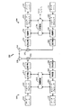
図1は複数のユーザをサポートし、本発明の種々の特徴を実行することができる無線通信システム100 の概略図である。システム100 は多数のセルに対して通信を行い、各セルは対応する基地局104 によりサービスされる。基地局はまた通常ベーストランシーバシステム(BTS)とも呼ばれている。種々の移動局または遠隔端末106 はシステム全体で分散されている。各移動局106 は移動局がアクチブであるか否かおよびソフトハンドオフ中であるか否かに基づいて、任意の特定の瞬間に順方向リンクおよび逆方向リンクで1以上の基地局104 と通信することができる。順方向リンクは基地局104 から移動局106 への送信を意味し、逆方向リンクは移動局106 から基地局104 への送信を意味している。図1に示されているように、基地局104Aは移動局106A、106B、106C、106Dと通信し、基地局104Bは移動局106D、106E、106Fと通信する。移動局106Dはソフトハンドオフ中であり、同時に基地局104Aと104Bと通信している。
【0013】
システム100 では、基地局制御装置(BSC)102 は基地局104 と結合し、さらに公共交換電話網(PSTN)に結合されている。PSTNへの結合は移動体交換センタ(MSC)により実現され、これは図面を簡明にするために図1には示されていない。BSC102 はそこに結合されている基地局の調節および制御を行う。BSC102 はさらに移動局106 間および移動局106 とPSTN(例えば一般的な電話機)およびパケットネットワークに結合するユーザ間の電話呼の伝送を基地局104 を介して制御する。
【0014】
システム100 は(1)“TIA/EIA-95-B Mobile Station-Base Station Compatibility Standard for Dual-Mode Wideband Spread Spectrum Cellular System”(IS-95 標準)、(2)“3rd Generation Partnership Project”(3GPP)という名称の組合により提出され、文書番号3G TS 25.211、3G TS 25.212、3G TS 25.213、3G TS 25.214(W−CDMA標準)を含む1組の文書で実施されている文献、(3)“3rd Generation Partnership Project2 ”(3GPP2 )という名称の組合により提出され、文書番号C.S0002-A 、C.S0005-A 、C.S0010-A 、C.S0011-A 、C.S0024 、C.S0026 (cdma2000標準)を含む1組の文献等に示されるような1以上のCDMA標準方式をサポートするように設計されている。3GPPおよび3GPP2文書の場合、これらは世界規模の標準的なボディ(例えばTIA、ETSI、ARIB、TTA、CWTS)により地域的な標準に変換され、国際電気通信連合(ITU)による国際標準に変換される。これらの標準はここで参考文献とされている。
【0015】
図2は基地局204 と移動局206 の1実施形態の簡単なブロック図であり、これらは本発明の種々の特徴を実行することができる。特定の通信では、音声データ、パケットデータおよび/またはメッセージは基地局204 と移動局206 との間でエアインターフェース208 を介して交換される。基地局と移動局間に通信セッションを設けるために使用されるメッセージおよびデータ送信の制御に使用されるメッセージ(例えばパワー制御、データレート情報、受取り等)のような種々のタイプのメッセージが送信される。これらのメッセージの幾つかのタイプを以下さらに詳細に説明する。
【0016】
逆方向リンクでは、移動局206 で、(例えばデータソース210 からの)音声および/またはパケットデータと(例えば制御装置230 からの)メッセージは送信(TX)データプロセッサ212 へ与えられ、この送信(TX)データプロセッサ212 はコード化されたデータを発生するためデータおよびメッセージを1以上のコード化方式でフォーマットし符号化する。各コード化方式は巡回冗長検査(CRC)、重畳、ターボ、ブロック、その他のコード化または全くコード化なしの任意の組合わせを含んでいる。音声データ、パケットデータ、メッセージは異なる方式を使用してコード化され、異なるタイプのメッセージは相違してコード化されてもよい。
【0017】
コード化されたデータはその後変調器(MOD)214 へ与えられ、さらに処理される(例えばカバーされ、短いPNシーケンスで拡散され、移動局に割当てられた長いPNシーケンスでスクランブルされる)。変調されたデータはその後、逆方向リンク信号を発生するために送信機“TMTR”216 へ与えられ調節される(例えば1以上のアナログ信号に変換され、増幅され、濾波され、直交変調される)。逆方向リンク信号はデュプレクサ(D)218 を経て伝送され、アンテナ220 を経て基地局204 へ送信される。
【0018】
基地局204 においては、逆方向リンク信号はアンテナ250 により受信され、デュプレクサ252 を経て伝送され、受信機“RCVR”254 へ与えられる。受信機254 は受信された信号を調節し(例えば濾波、増幅、下方変換、デジタル化)、サンプルを提供する。復調器“DEMOD”256 は再生されたシンボルを与えるためサンプルを受信し処理する(例えばデスプレッド、デカバー、パイロット復調)。復調器256 は受信された信号の多数のインスタンスを処理し、結合されたシンボルを発生するレーク受信機を構成する。受信(RX)データプロセッサ258 はその後、逆方向リンクで送信されたデータおよびメッセージを再生するためにシンボルを復号する。再生された音声/パケットデータはデータシンク260 へ与えられ、再生されたメッセージは制御装置270 へ与えられる。復調器256 とRXデータプロセッサ258 による処理は遠隔端末206 で実行される処理に対して相補的である。復調器256 とRXデータプロセッサ258 は多数のチャンネル、例えば逆方向基本チャンネル(R−FCH)および逆方向補足チャンネル(R−SCH)により受信された多数の送信を処理するようにさらに動作される。また、送信は多数の遠隔端末から同時に行われてもよく、各遠隔端末は逆方向基本チャンネル、逆方向補足チャンネルまたはその両者で送信することができる。
【0019】
順方向リンクでは、基地局204 で、(例えばデータソース262 からの)音声および/またはパケットデータと(例えば制御装置270 からの)メッセージは送信(TX)データプロセッサ264 により処理され(例えばフォーマットされ符号化され)、さらに変調器(MOD)266 により処理され(例えばカバーされ拡散され)、順方向リンク信号を発生するために送信機“TMTR”268 により調整される(例えばアナログ信号に変換され、増幅され、濾波され、直角変調される)。順方向リンク信号はデュプレクサ(D)252 を通って伝送され、アンテナ250 により移動局206 へ送信される。
【0020】
移動局206 において、順方向リンク信号はアンテナ220 により受信され、デュプレクサ(D)218 を通して伝送され、受信機“RCVR”222 へ与えられる。受信機222 は受信された信号を調整し(例えば下方変換、濾波、増幅、直角変調、デジタル化)、サンプルを与える。サンプルはシンボルを与えるために復調器(DEMOD)224 により処理されて(例えばデスプレッド、デカバー、パイロット復調)シンボルが得られ、そのシンボルは順方向リンクで送信されたデータおよびメッセージを再生するために受信(RX)データプロセッサ226 によりさらに処理される(例えば復号およびチェック)。再生されたデータはデータシンク228 へ与えられ、再生されたメッセージは制御装置230 へ与えられる。
【0021】
[アーキテクチャ基準モデル]
図2で与えられたシステムは基地局204 (以後“アクセスネットワーク”という)、移動局206 (以後“アクセス端末”という)、およびアクセスネットワークとアクセス端末との間のエアインターフェース208 を含んでいるアーキテクチャ基準モデルとして考慮されている。通常、アクセスネットワーク(AN)はインターネットのようなパケット交換データネットワークとアクセス端末(AT)との間にデータ接続を設けるネットワーク装置を含んでいる。ATはユーザへデータ接続を設ける装置を含んでいる。ATはラップトップパーソナルコンピュータ等のコンピュータ装置に接続されるか、またはパーソナルデジタルアシスタント(PDA)等の自蔵データ装置であってもよい。ATは可動または静止型であり、1以上の基地局と通信する。ATは1以上のモデムプールトランシーバにより基地局モデムプール制御装置との間でデータパケットを送信し受信する。モデムプールトランシーバとモデムプール制御装置はアクセスネットワークの一部であってもよい。ATは無線チャンネルまたは有線チャンネル、例えば光ファイバ或いは同軸ケーブルの使用により通信する任意のデータ装置である。ATはさらにPCカード、コンパクトフラッシュ、外部または内部モデムまたは無線またはワイヤライン電話機を含む任意の1つの装置であってもよいが、それらに限定されない。アクセス端末が信号をモデムプールトランシーバへ送信する通信リンクは逆方向リンクと呼ばれる。モデムプールトランシーバが信号をアクセス端末へ送信する通信リンクは順方向リンクと呼ばれる。
【0022】
[プロトコルアーキテクチャ]
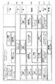
エアインターフェース208 (図2)は層をなしており、インターフェースが各層および、各層内の各プロトコルに対して規定されており、それ故、層およびプロトコルにはスケール能力が与えられている。表1はエアインターフェース208 の層をなしたアーキテクチャを示している。各層は層の機能を行う1以上のプロトコルを含んでもよい。
表1.エアインターフェースの階層構造
アプリケーション層
ストリーム層
セッション層
接続層
セキュリティ層
MAC層
物理層
各層内のプロトコルは情報をエアリンクの他方の側のピアエンティティへ伝達するためシグナリングメッセージまたはヘッダを使用する。プロトコルがメッセージを送信するとき、これらはこれらのメッセージを送信するためにシグナリングネットワークプロトコル(SNP)を使用する。
【0023】
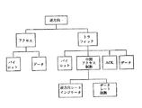
図3は本発明の1実施形態にしたがって、表1に示された各層で規定されているプロトコルを示している。これらのプロトコルを以下、簡単に説明する。
【0024】
アプリケーション層302 は以下のプロトコルを含んでいる。
シグナリングネットワークプロトコル(SNP):これはシグナリングメッセージのメッセージ送信サービスを提供する。
シグナリングリンクプロトコル(SLP):これはシグナリングメッセージの確実で最善の転送機構を伴って断片化機構を与え、デフォルトシグナリングアプリケーションのコンテキストで使用されるとき、SNPパケットを伝送する。
【0025】
無線リンクプロトコル(RLP):これは再送信を行いデータ流の検出を二倍にする。
位置更新プロトコル:これはデフォルトパケットアプリケーションの可動管理をサポートする位置更新手順およびメッセージを規定する。
フロー制御プロトコル:これはパケットアプリケーションデータ流をエネーブルおよびディスエーブルするフロー制御手順を規定する。
【0026】
ストリーム層304 は送信方向においてストリームヘッダを付加し、ストリームヘッダを除去し、パケットを受信エンティティの正確なアプリケーションへ転送する。
【0027】
セッション層306 は以下のプロトコルを含んでいる。
セッション管理プロトコル:これはセッションキープアライブ(alive )機構ならびにアドレス管理プロトコルおよびセッション構成プロトコルの付勢および減勢を制御する手段を与える。
アドレス管理プロトコル:これはアクセス端末識別子(ATI)管理を行う。
セッション構成プロトコル:これは1セッションで使用されるプロトコルの交渉および構成を行う。
【0028】
接続層308 はエアインターフェースの状態を制御し、そこを通って送信されたトラフィックに優先順位を付ける。接続は閉または開のいずれかである。
【0029】
閉接続:接続が閉じたとき、アクセス端末は専用のエアリンクリソースを割当てられない。アクセス端末とアクセスネットワークとの間の通信はアクセスチャンネルと制御チャンネルで行われる。
【0030】
開接続:接続が開いたとき、アクセス端末は順方向トラフィックチャンネル、逆方向パワー制御チャンネル、逆方向トラフィックチャンネルを割当てられる。アクセス端末とアクセスネットワーク間の通信はこれらの割当てられたチャンネルと制御チャンネルによって行われる。
【0031】
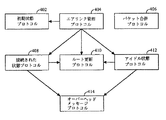
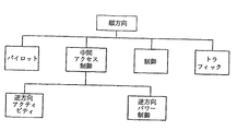
接続層は1実施形態にしたがって、図4で示されているように組織される。
【0032】
初期状態プロトコル402 :このプロトコルはアクセスネットワークの獲得に関連する動作を行う。
【0033】
エアリンク管理プロトコル404 :このプロトコルはアクセス端末とアクセスネットワークの全体的な接続状態を維持する。このプロトコルはアクセス端末がネットワークを既に獲得しているか(初期状態)、ネットワークを獲得しているが接続が閉じているか(アイドル状態)またはアクセスネットワークと開接続しているか(接続状態)に対応して3つの状態の1つである。このプロトコルは現在の状態の機能として以下の3つのプロトコルの1つを付勢する。
【0034】
パケット合併プロトコル406 :このプロトコルは割当てられた優先順位およびターゲット送信チャンネルの機能として送信するためパケットを合併し優先順位を付ける。
【0035】
接続状態プロトコル408 :このプロトコルは開接続を有するアクセス端末に関連する動作を行い、アクセス端末とアクセスネットワークとの間の無線リンクを管理する。
【0036】
ルート更新プロトコル410 :このプロトコルはアクセス端末の位置の追跡を維持し、アクセス端末とアクセスネットワークとの間に無線リンクを維持することに関連する動作を行う。このプロトコルもパイロットにおいて管理を行う。
【0037】
アイドル状態プロトコル412 :このプロトコルはネットワークを獲得しているが開接続を持たないアクセス端末に関連する動作を行い、この動作は実効的なページング、接続を開くこと、アクセス端末パワー節約をサポートするためにアクセス端末のおおよその位置の追跡を維持することを含んでいる。
【0038】
オーバーヘッドメッセージプロトコル414 :このプロトコルは制御チャンネルによって基本的なパラメータを放送する。これらのパラメータは接続層のプロトコルおよび他の層のプロトコルにより共有される。このプロトコルもまた接続層機能を維持するのに必要なメッセージの管理を行う。
【0039】
エアリンク管理プロトコルと、その子孫、およびオーバーヘッドメッセージプロトコルは制御プロトコルである。パケット合併プロトコルは送信され受信されたデータについて動作する。
【0040】
セキュリティ層310 は以下のプロトコルを含んでいる。
キー交換プロトコル:これは認証および暗号化のためにセキュリティーキーを交換するためにアクセスネットワークとアクセス端末により後続される手順を行う。
認証プロトコル:これはトラフィックの認証のためアクセスネットワークとアクセス端末により後続される手順を行う。
暗号化プロトコル:これはトラフィックの暗号化のためにアクセスネットワークとアクセス端末により後続される手順を行う。
セキュリティプロトコル:これは認証プロトコルと暗号化プロトコルにより使用されることができるコードの発生のための手順を行う。
【0041】
MAC層312 は以下のプロトコルを含んでいる。
制御チャンネル中間アクセス制御(MAC)プロトコル:これは送信のためのアクセスネットワークと制御チャンネルの受信のためのアクセス端末とにより後続される手順を行う。
アクセスチャンネルMACプロトコル:これは送信のためにアクセス端末により、またアクセスチャンネルの受信のためにアクセスネットワークにより後続される手順を行う。
順方向トラフィックチャンネルMACプロトコル:これは送信のためにアクセスネットワークにより、また順方向トラフィックチャンネルの受信のためにアクセス端末により後続される手順を行う。
逆方向トラフィックチャンネルMACプロトコル:これは送信のためにアクセス端末により、また逆方向トラフィックチャンネルの受信のためにアクセスネットワークより後続される手順を行う。
【0042】
物理層314 は順方向および逆方向リンクのチャンネル構造、周波数、パワー出力および変調仕様を与える。
【0043】
[アイドル状態プロトコル]
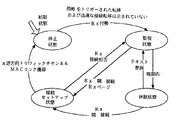
アイドル状態プロトコル412 はアクセス端末がネットワークを獲得し、接続が開かれていないときアクセス端末とアクセスネットワークにより使用される手順およびメッセージを提供する。このプロトコルはアクセス端末の状態転移を示している図5と、アクセスネットワークの状態転移を示している図6とに示されているように、以下の4つの状態の1つで動作する。
【0044】
休止状態:この状態では、プロトコルは付勢コマンドを待機する。
休眠状態:この状態では、アクセス端末はパワーを節約するためにそのサブシステムの一部を遮断する。アクセス端末は順方向チャンネルを監視せず、アクセスネットワークはアクセス端末へ導かれるユニキャストパケットを送信しない。
【0045】
監視状態:この状態では、アクセス端末は制御チャンネルを監視し、ページメッセージを聞き、必要ならばオーバーヘッドメッセージプロトコルから受信されたパラメータを更新する。アクセスネットワークはこの状態でアクセス端末にユニキャストパケットを送信する。
【0046】
接続セットアップ状態:この状態では、アクセス端末とアクセスネットワークは接続をセットアップできる。
【0047】
アイドル状態プロトコル412 (図4)はアクセス端末により制御チャンネルの周期的なネットワーク監視をサポートし、以下の例示的なアクセス端末動作モード下で大きなパワー節約を可能にする。
連続動作:これにおいてはアクセス端末が連続して制御チャンネルを監視する。
中断モード動作:これにおいてはアクセス端末が時間期間だけ連続して制御チャンネルを監視し、続いてスロットモードで動作する。中断モードに続いてエアリンク管理プロトコル動作が行われ、迅速なネットワーク開始再接続が可能である。
スロットされたモード動作:アクセス端末は選択されたスロットのセットを監視する。
【0048】
[休眠状態]
アクセス端末が休眠状態であるとき、制御チャンネルの監視を停止することができる。この状態では、アクセス端末はパワーの消費を減少するため幾つかのリソースの処理を中断する。アクセス端末が接続を開くことを必要とするならば、接続セットアップ状態に転移する。アクセスネットワークが休眠状態にあるとき、ユニキャストパケットをアクセス端末へ送信することが禁止されてもよい。アクセスネットワークとアクセス端末は各制御チャンネルサイクルにおいて送信される同期的なカプセルをそれぞれ送信し受信する時間に休眠状態から監視状態へ転移する。
【0049】
[監視状態]
アクセス端末が監視状態であるとき、制御チャンネルを監視する。アクセスネットワークが監視状態であるとき、ユニキャストパケットをアクセス端末へ送信する。アクセス端末は監視状態であるときCDMAチャンネルを選択し、オーバーヘッドメッセージプロトコルセクションで特定されたようにオーバーヘッドメッセージを監視する。
【0050】
監視状態のアクセス端末は以下の条件が満たされるならば休眠状態に転移する。
アクセス端末は監視状態に入って以来送信しているという1つ1つのアクセスプローブに対する応答を受信している。
アクセス端末は監視状態に入って以来受信しているという1つ1つの“アクセスチャンネルMAC.Tx開始”指示に対して“アクセスチャンネルMAC.Tx終了”指示を受信している。
アクセス端末は現在が中断期間であることを公示していない。関連する接続閉メッセージで公示されている時間が現在のシステム時間よりも大きいならば、中断期間は現在である。
【0051】
[オーバーヘッドメッセージプロトコル]
迅速な構成メッセージとセクタパラメータメッセージは集合的にオーバーヘッドメッセージと呼ばれている。アクセスネットワークはこれらのメッセージを制御チャンネルによって放送する。これらのメッセージは多数のプロトコルに関与し、それ故別々に特定される。オーバーヘッドメッセージプロトコルはこれらのメッセージの送信、受信、監督に関連する手順を行う。このプロトコルは以下の2つの状態の一方である。
休止状態:この状態では、プロトコルは付勢コマンドを待機する。この状態はアクセス端末のみに対応し、アクセス端末がアクセスネットワークを獲得していないかオーバーヘッドメッセージを受信する必要がないときに生じる。
アクチブ状態:この状態では、アクセスネットワークはオーバーヘッドメッセージを送信し、アクセス端末はそれを受信する。
【0052】
アクセスネットワークは1つ1つの同期的なカプセル(SC)に、アクセスネットワークが制御チャンネルサイクル(CCC)で送信することのできる迅速な構成メッセージ(QCM)を含んでいる。アクセスネットワークはまた少なくとも一度1つ1つの特定された数のCCCでSC中にセクタパラメータメッセージを含んでいる。アクセスネットワークはQCMのオーバーヘッド署名フィールドを次のセクタパラメータメッセージのオーバーヘッド署名フィールドへ設定する。アクセス端末が更新されたオーバーヘッドメッセージを維持することを必要とするとき、以下説明するようにQCMとセクタパラメータメッセージについて管理を行う。
【0053】
アクセス端末がQCMを受信したとき、そこからオーバーヘッド署名を決定することができる。受信されたQCMのオーバーヘッド署名フィールドの値がオーバーヘッド署名の記憶された値と異なるならば、アクセス端末はそれが最新のセクタパラメータメッセージを受信するまで次のSCを監視する。そうでなければアクセス端末は休眠状態へ転移する。
【0054】
アクセス端末が一度最新のセクタパラメータメッセージを受信すると、将来比較するためにメッセージに関連するオーバーヘッド署名を記憶する。アクセス端末は先に監視されたセクタからのパラメータの獲得の速度を高めるためにオーバーヘッドメッセージパラメータおよび署名をキャッシュ(記憶)する。
【0055】
[迅速な構成メッセージ]
迅速な構成メッセージ(QCM)はオーバーヘッドメッセージ内容の変化と他の頻繁に変化する情報を示すために使用される。QCMはオーバーヘッド署名フィールドのようなフィールドを含んでいる。アクセスネットワークはそれが送信する次のセクタのパラメータメッセージのオーバーヘッド署名フィールドの値へこのフィールドを設定する。
【0056】
[セクタパラメータメッセージ]
セクタパラメータメッセージはセクタの特別な情報をアクセス端末へ伝送するために使用されることができる。セクタパラメータはオーバーヘッド署名フィールドのようなフィールドを含むことができる。アクセスネットワークはセクタパラメータメッセージの内容が変化したならばこのフィールドを変更することができる。
【0057】
[MAC層]
MAC層312 (図3)は以下説明するように、制御チャンネル、アクセスチャンネル、順方向トラフィックチャンネル、逆方向トラフィックチャンネルの動作を支配するルールを含んでいる。
【0058】
制御チャンネルMACプロトコル:このプロトコルは1以上のセキュリティ層パケットから制御チャンネルMAC層パケットを作成する。このプロトコルは制御チャンネルにおけるアクセスネットワーク送信およびパケットスケジュール化、制御チャンネルの端末獲得、制御チャンネルMAC層パケット受信に関するルールを含んでいる。このプロトコルはまた送信パケットへアクセス端末アドレスを付加することができる。
【0059】
アクセスチャンネルMACプロトコル:このプロトコルはアクセスチャンネルの送信タイミングおよびパワー特性を支配するルールを含んでいる。
【0060】
順方向トラフィックチャンネルMACプロトコル:このプロトコルは順方向トラフィックチャンネルの動作を支配するルールを含んでいる。このプロトコルはデータレート制御チャンネルを送信するときにアクセス端末がしたがうルールと共に、アクセスネットワークがこのチャンネルの解釈に使用するルールを含んでいる。このプロトコルは順方向トラフィックチャンネルの可変レートと固定レートの両動作をサポートする。
【0061】
逆方向トラフィックチャンネルMACプロトコル:このプロトコルは逆方向トラフィックチャンネルの動作を支配するルールを含んでいる。このプロトコルはアクセスネットワークが逆方向トラフィックチャンネルを獲得することを助けるためにアクセス端末がしたがうルールを含んでいる。このプロトコルはまたアクセス端末とアクセスネットワークが逆方向トラフィックチャンネルの送信レートを選択するためにしたがうルールを含んでいる。
【0062】
送信方向では、MAC層はセキュリティ層パケットを受信し、層に関連するヘッダ、トレーラ、パッディングを付加し、物理層へ送信するための結果的なパケットを転送する。受信方向では、MAC層は物理層からMACパケットを受信し、層に関連するヘッダ、トレーラ、パッディングを除去した後、それらをセキュリティ層へ転送する。
【0063】
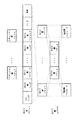
図7は制御チャンネル、アクセスチャンネル、順方向および逆方向トラフィックチャンネルにおけるセキュリティ層パケット、MACパケット、物理層パケットの間の関係を示している。
【0064】
[制御チャンネルMACプロトコル]
制御チャンネルMACプロトコルはアクセスネットワークが制御チャンネルを送信し、アクセス端末がそれを受信するのに必要な手順およびメッセージを提供することができる。アクセスネットワークは全てのアクセス端末でこのプロトコルの1つのインスタンスを有する。このプロトコルは以下の2つの状態の一方である。
休止状態:この状態では、プロトコルは付勢コマンドを待機する。この状態はアクセス端末にのみ対応し、アクセス端末がアクセスネットワークを獲得していないか制御チャンネルを監視していないときに生じる。
アクチブ状態:この状態ではアクセスネットワークは制御チャンネルを送信し、アクセス端末はそれを受信する。
【0065】
このプロトコルの送信装置は以下に示されているように制御チャンネルMAC層パケットであってもよく、例えば、
【数1】

制御チャンネルMACプロトコルは物理層へ送信するためのMAC層パケットを送信することができる。制御チャンネルMAC層パケットは、特定の時間に送信される同期的なカプセルかまたは同期的なカプセルが送信されるときを除く任意の時間に送信される非同期的カプセルで送信される。同期的なカプセルは1以上の制御チャンネルMAC層パケットを含んでいる。非同期的カプセルは1つの制御チャンネルMAC層パケットを含んでいる。
【0067】
[制御チャンネルサイクル]
CCCは例えば256スロット期間として規定され、これはシステム時間で同期しており、即ちCCCの開始とシステム時間の開始との間に256の整数倍のスロットが存在する。
【0068】
アクセスネットワークは単位セクタ当りで動作する制御チャンネルMACプロトコルの1インスタンスを有していてもよい。アクセスネットワークはSCでの送信を目的としている保留のセキュリティ層パケットからSCを構成する。
【0069】
[物理層チャンネル]
物理層414 (図3)は図8と9で示されている物理層チャンネルと順方向および逆方向チャンネル階層を規定する。
【0070】
順方向チャンネルは以下の時間多重化チャンネル、即ちパイロットチャンネル、順方向中間アクセス制御(MAC)チャンネル、順方向トラフィックチャンネル、制御チャンネルを含んでいる。トラフィックチャンネルはユーザデータの物理層パケットを伝送する。制御チャンネルは制御メッセージを伝送し、またユーザトラフィックを伝送してもよい。各チャンネルは符号分割多元直交ウォルシュチャンネルへさらに分解される。
【0071】
順方向リンクはそれぞれ例えば2048チップの長さを有するスロットからなる。16スロットのグループはゼロオフセットPNシーケンスのPNロールへ割当てられ、偶数の秒毎にシステム時間に整列される。各スロット内において、パイロット、MAC、トラフィックまたは制御チャンネルは時分割多重化され、同じパワーレベルで送信されることができる。
【0072】
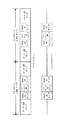
図10は例示的な順方向リンクスロット構造を示している。
【0073】
制御チャンネルは76.8KBPSまたは38.4KBPSの例示的なレートでアクセス端末誘導メッセージを送信する。制御チャンネルの変調特性は対応するデータレートの順方向トラフィックチャンネルの変調特性と同じである。制御チャンネル送信はプリアンブルを有することにより順方向トラフィックチャンネル送信から弁別される。
【0074】
図11は制御チャンネルの周期的な監視方式1100を示している。アクセス端末は周期的な監視サイクルで制御チャンネルを監視する。監視サイクルは複数のCCC1102、1104を含んでいてもよい。この整列では、アクセス端末はウェークの状態であり、ATに導かれるパケットとオーバーヘッドメッセージに対して各SC1106、1108を連続して監視しなければならない。
【0075】
オーバーヘッドメッセージはQCMおよびセクタパラメータを含んでいる。セクタパラメータはアクセス端末へ導かれるユニキャストパラメータとオーバーヘッドパラメータとを含んでいる。オーバーヘッドパラメータはアクセス端末に重要なシステム構成パラメータを通知するために制御チャンネルによって送信される。これらのパラメータはシステムパラメータ、アクセスパラメータ、近隣リストを含むことができる。システムパラメータはハンドオフパラメータと順方向パワー制御パラメータを含むことができる。アクセスパラメータは逆方向パワー制御パラメータ、アクセスパラメータ、アクセスチャンネルパラメータを含むことができる。近隣リストはアクセス端末が使用する近傍セクタのリストを含むことができる。オーバーヘッドパラメータはATに導かれるメッセージと同程度に頻繁に更新される必要はない。ユニキャストパラメータは頻繁に例えばSC1106、1108毎に更新される必要があるが、オーバーヘッドパラメータは頻繁に更新される必要はない。
【0076】
制御チャンネル監視方式では、図11により表されているように、基地局へ送信される新しいオーバーヘッドパラメータが現在存在しなくても、移動局は制御チャンネルで送信されるSC1106、1108を連続して監視しなければならない。これはSC1106、1108の送信中の任意の点でアクセスネットワークがユニキャストパケットを送信するためである。これはウェーク状態を維持し、既に受信されて記憶されている冗長オーバーヘッドパラメータを受信することに貴重な電池寿命を受信アクセス端末に使用させている。
【0077】
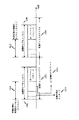
図12は本発明の1実施形態にしたがった制御チャンネルの周期的な監視方式1200を示している。アクセス端末は監視サイクルで制御チャンネルを周期的に監視し、これは1以上のCCCインターバル1202と1204を含んでいる。本発明の1実施形態では、監視サイクルは12のCCCまたは5.12秒を含んでいる。SC1206、1208が送信される期間の時間インターバルは第1の時間期間と第2の時間期間とを含んでいる。第1の時間期間中の休眠状態同期的カプセル(SSSC)1210、1212では、アクセスネットワークはQCM1214と1以上のATに導かれるパケット1216を送信する。ATに導かれるパケットはアクセス端末へ導かれるユニキャストメッセージおよびパラメータを含んでいる。アクセスネットワークは第2の時間インターバル中に、SC1206、1208に含まれているオーバーヘッドパラメータのセットもまた送信する。アクセスネットワークは例えばオーバーヘッド署名等の証印を両者に含めることによって同一のSCで送信されるオーバーヘッドパラメータの比較セットへQCMをユニークにリンクする。
【0078】
本発明の1実施形態によれば、アクセスネットワークは第2の時間期間中に送信されるオーバーヘッドパラメータとは別に、第1の時間期間中にQCM1214とATに導かれるパケット1216とを送信することができる。それ故、アクセス端末は図12、13に関連して以下説明するようにSSSC1210、1212だけを監視する必要がある。
【0079】
ステップ1302(図13)で、制御チャンネルの初期SC1206を監視するとき、アクセス端末はステップ1304で初期SSSC1210中にQCM1214を受信する。ステップ1306で、アクセス端末は受信されたQCM1214から初期オーバーヘッド署名を決定する。ステップ1308で、アクセス端末は初期オーバーヘッド署名(OS)を記憶する。アクセス端末はまた同一の初期SSSC1210中にATに導かれるパケット1216を受信する。続いてステップ1310で、アクセス端末は同一の初期SC1206に含まれるオーバーヘッドパラメータの初期セットを受信し記憶し、これは第2の時間インターバル中に送信される、その後、アクセス端末は休眠モードになるか、或いは残りの初期CCC時間期間1202で初期SC1206の最後に待機モードに入る。
【0080】
アクセス端末はその後のSC1208を監視するために後続するCCC1204の開始でウェークアップする。そうすることで、アクセス端末はステップ1312でSSSC1212を監視し、ステップ1314で新しいQCMを受信し、ステップ1316でそこからオーバーヘッド署名を決定する、アクセス端末が最新のオーバーヘッドパラメータを含んでいるか否かを決定し、したがってSC期間全体の制御チャンネルの監視を避けるために、アクセス端末はステップ1318で以前に保存されたオーバーヘッド署名を現在受信したオーバーヘッド署名と比較する。これらのオーバーヘッド署名が一致したならば、アクセス端末はオーバーヘッドパラメータの最新のセットを含んでおり、したがってアクセス端末はステップ1320でさらに制御チャンネルを監視するのを停止する。この場合、アクセス端末は休眠モードになるか待機モードに入る。本発明の1実施形態によれば、アクセス端末は現在のSSSC1212の最後に休眠状態になる。アクセス端末は次の監視サイクルまで、即ちステップ1312で次のSCを監視するためにステップ1324でアクセス端末がウェークアップするときまで休眠モードである。
【0081】
しかしながら、現在受信されたオーバーヘッド署名が最も最近記憶されたオーバーヘッド署名と一致しないならば、アクセス端末は最も更新されたオーバーヘッドパラメータをもたず、したがってアクセス端末はアクセス端末がオーバーヘッドパラメータの最新セットを適切に受信するまで次のSCを監視し続けなければならない。それ故、ステップ1326でアクセス端末は現在のオーバーヘッド署名を記憶し、ステップ1328でアクセス端末は現在のオーバーヘッドパラメータを受信して記憶する。アクセス端末はもう一方のQCMに含まれるオーバーヘッド署名と同一のオーバーヘッド署名を有するオーバーヘッドパラメータのセットを見つけるまでその次のSCを監視し続ける。この場合、アクセス端末はそれがオーバーヘッドパラメータの最新セットを適切に受信し記憶した後、休眠モードになるか待機モードに入る。本発明の1実施形態によれば、アクセス端末は現在のSCの最後またはその前に休眠モードに入り、これはオーバーヘッドパラメータの最新セットを伝播する。この場合、アクセス端末は現在の残りの監視サイクルで休眠モードを続ける。
【0082】
本発明の1実施形態にしたがって、前述したように制御チャンネルのオーバーヘッドパラメータのバルクな送信からATに導かれるメッセージの送信を分離することによって、アクセス端末はSSSCの最後で制御チャンネルの監視を停止することができる。アクセス端末がすぐに例えばSSSCの最後に休眠モードに入ることを可能にすることは、さらに電池寿命を有効に節約する。
【0083】
任意の種々の異なる技術および方法を使用して情報および信号が表されることを当業者は理解するであろう。例えば、前述の説明を通して参照されたデータ、命令、コマンド、情報、信号、ビット、シンボル、チップは電圧、電流、電磁波、磁界または粒子、光フィールドまたは粒子、或いは任意のその組合わせにより表されることができる。
【0084】
ここで説明した実施形態を伴った種々の図示の論理ブロック、モジュール、回路、アルゴリズムステップは電子ハードウェア、コンピュータソフトウェア、または両者の組合わせとして構成されることをさらに当業者は認識するであろう。ハードウェアとソフトウェアのこの交換性を明白に示すため、種々の例示のコンポーネント、ブロック、モジュール、回路、ステップをそれらの機能に関して前述した。このような機能はハードウェアまたはソフトウェアとして構成されるかはシステム全体に課された特定の応用と設計制約に基づいている。当業者は説明した機能を各特定のアプリケーションで可変の方法を実施するが、このような構成の決定は本発明の技術的範囲から逸脱すると解釈されるべきではない。
【0085】
ここで説明した実施形態を伴って説明された種々の例示の論理ブロック、モジュール、回路は汎用目的のプロセッサ、デジタル信号プロセッサ(DSP)、特定用途向け集積回路(ASIC)、フィールドプログラム可能なゲートアレイ(FPGA)、または他のプログラム可能な論理装置、ディスクリートなゲートまたはトランジスタ論理装置、ディスクリートなハードウェアコンポーネントまたはここで説明した機能を行うように設計された任意のその組合わせで構成され、または実行される。汎用目的のプロセッサはマイクロプロセッサであってもよいが、その代わりに、プロセッサは任意の通常のプロセッサ、制御装置、マイクロ制御装置または状態マシーンであってもよい。プロセッサはまたコンピュータ装置の組合わせ、例えばDSPとマイクロプロセッサ、複数のマイクロプロセッサ、DSPコア或いは任意の他のこのような構造を伴った1以上のマイクロプロセッサとして構成されることもできる。
【0086】
ここで説明した実施形態を伴って説明された方法またはアルゴリズムのステップはハードウェアで、プロセッサにより実行されるソフトウェアモジュールで、または2つの組合わせで直接実施されてもよい。ソフトウェアモジュールはRAMメモリ、フラッシュメモリ、ROMメモリ、EPROMメモリ、EEPROMメモリ、レジスタ、ハードディスク、取出し可能なディスク、CD−ROM、または技術で知られている任意の他の形態の記憶媒体に存在する。例示的な記憶媒体はプロセッサが記憶媒体から情報を読取り、そこへ情報を書込めるようにプロセッサに結合されている。その代わりに、記憶媒体はプロセッサと一体でもよい。プロセッサおよび記憶媒体はASICに配置されてもよい。ASICはアクセス端末に配置されることができる。その代わりに、プロセッサおよび記憶媒体はアクセス端末のディスクリートなコンポーネントとして存在してもよい。
【0087】
開示された実施形態の前述の説明は当業者が本発明を実行または使用できるようにするために行なわれた。これらの実施形態に対する種々の変形は当業者には容易に明白であり、ここで規定されている一般原理は本発明の技術的範囲を逸脱せずに他の実施形態に応用されてもよい。したがって本発明はここで示した実施形態に限定されることを意図するものではなく、ここで説明した原理および優秀な特徴と一貫して最も広範囲にしたがうことを意図している。
【図面の簡単な説明】
【0088】
【図1】複数のユーザをサポートする無線通信システムの概略図。
【図2】基地局と移動局の1実施形態の簡単化されたブロック図。
【図3】エアインターフェースのプロトコルを表した図。
【図4】接続層のプロトコルを表した図。
【図5】アイドル状態のプロトコルの状態図。
【図6】アイドル状態のプロトコルの状態図。
【図7】MAC層パケットとカプセルを表した図。
【図8】順方向リンクチャンネルを表した図。
【図9】逆方向リンクチャンネルを表した図。
【図10】順方向リンクスロット構造を表した図。
【図11】制御チャンネルの周期的な監視方式を表した図。
【図12】制御チャンネルの周期的な監視方式を表した図。
【図13】制御チャンネルの周期的な監視方式のフローチャート。【Technical field】
[0001]
The present invention relates generally to communication technology, and more particularly to maximizing standby time while monitoring a control channel.
[Background Art]
[0002]
Telecommunications systems, such as the IS-95 family of CDMA wireless telecommunications systems, include several types of coded channels originating from base stations or cell sites and some types originating from mobile stations or subscriber units. There are types of coded channels. These channels include those channels that carry the necessary control data and signals, and those channels that carry voice, data, and control data.
[0003]
The control channel transmits messages and parameters required by the mobile station for access and paging operations. The messages and parameters transmit system parameters, access parameters, neighbor list, mobile guidance paging message, mobile guidance commands, and channel assignment information to the mobile station. The control channel is used for communication with the mobile station when there is no call in progress, ie when the mobile station is idle.
[0004]
In the idle state, the mobile station monitors mobile guidance messages and parameters transmitted from the base station on the forward link. The mobile station uses a sleep or standby mode when monitoring the control channel. During the dormant or standby mode, the mobile station goes to sleep, i.e. shuts off unnecessary functions and wakes up periodically to monitor the control channel.
[0005]
U.S. Patent No. 6,111,865 (named "DUAL CHANNEL SLOTTED PAGING"), which is incorporated herein by reference, and U.S. Patent Application Serial No. 09 / 272,802, filed March 19, 1999 (Title of Invention) The paging method described in “METHOD AND APPARATUS FOR SUPERVISING THE PERFORMANCE OF A QUICK PAGING CHANNEL IN A DUAL EVENT SLOTTED PAGING SYSTEM” shows the basic configuration of a full paging channel combined with a quick paging channel. .
[0006]
The base station inserts control channel information into the assigned control time slots, which it knows the mobile station will monitor. The mobile station monitors the forward link in a slotless mode or a slot mode. In the slotless mode, the mobile station continuously monitors the forward link. In the slot mode, the mobile station monitors the control channel only during the assigned control channel cycle. In the latter case, the mobile station operating in slot mode saves some battery power since the mobile station does not need to constantly monitor all slots. The control channel in the slot mode is disclosed in U.S. Pat. No. 5,509,015 (title of "METHOD AND APPARATUS FOR SCHEDULING COMMUNICATION BETWEEN TRANSCEIVERS") and U.S. Pat. The name "A METHOD AND APPARATUS FOR MAXIMIZING STANDBY TIME USING A QUICK PAGING CHANNEL") is described in further detail, both of which are assigned to the assignee of the present invention and incorporated herein by reference.
DISCLOSURE OF THE INVENTION
[Problems to be solved by the invention]
[0007]
Focusing on saving battery power, it is desirable to maximize the time that the mobile station is in sleep mode. Therefore, an efficient control channel monitoring system that increases the amount of time the mobile station is in a standby or dormant mode while ensuring that the mobile station receives all messages and parameters transmitted on the control channel quickly And methods are needed in the art.
[Means for Solving the Problems]
[0008]
According to one aspect of the present invention, a method for monitoring a control channel in a telecommunications system includes transmitting a packet directed to an access terminal during a first time period over an access network and transmitting a message during a first time period. Transmitting a set of overhead parameters during a second time period. The method further includes monitoring a control channel at the access terminal based on a relationship between the current and previous messages.
[0009]
According to another feature of the invention, the method for monitoring a control channel in a telecommunications system further comprises the step of receiving at the access terminal packets and messages directed to the access terminal during a first time interval. The method further includes monitoring the control channel to receive the set of overhead parameters transmitted during the second time period based on a relationship between the current message and a previous message. I have.
[0010]
According to another feature of the invention, a method of transmitting control channel information in a telecommunications system comprises transmitting a packet directed to an access terminal during a first time period, and transmitting a message during the first time period. , Transmitting a set of overhead parameters during a second time period.
[0011]
In the aforementioned features, the message and the set of overhead parameters may be linked together. Further, the access terminal needs to monitor the control channel only during the first time period if the current message indicates that the received set of overhead parameters is up to date. In this case, the access terminal enters a sleep mode at the end of the first time interval. Otherwise, the access terminal continues to monitor the control channel until it receives the latest set of overhead parameters.
BEST MODE FOR CARRYING OUT THE INVENTION
[0012]
The features, characteristics, and advantages of the present invention will become more apparent from the following detailed description, taken in conjunction with the drawings. The same reference numerals are the same throughout.
FIG. 1 is a schematic diagram of a
[0013]
In the
[0014]
[0015]
FIG. 2 is a simplified block diagram of one embodiment of
[0016]
On the reverse link, at the
[0017]
The coded data is then provided to a modulator (MOD) 214 for further processing (eg, covered, spread with a short PN sequence, and scrambled with a long PN sequence assigned to the mobile station). The modulated data is then provided to a transmitter "TMTR" 216 and modulated (e.g., converted to one or more analog signals, amplified, filtered, and quadrature modulated) to generate a reverse link signal. . The reverse link signal is transmitted via duplexer (D) 218 and transmitted to
[0018]
At
[0019]
On the forward link, at
[0020]
At
[0021]
[Architecture reference model]
The system provided in FIG. 2 includes a base station 204 (hereinafter "access network"), a mobile station 206 (hereinafter "access terminal"), and an
[0022]
[Protocol Architecture]
The air interface 208 (FIG. 2) is layered, with interfaces defined for each layer and for each protocol within each layer, thus providing the layers and protocols with scaling capabilities. Table 1 shows the layered architecture of the
Table 1. Air interface hierarchy
Application layer
Stream layer
Session layer
Connection layer
Security layer
MAC layer
Physical layer
Protocols within each layer use signaling messages or headers to convey information to peer entities on the other side of the airlink. When the protocols send messages, they use the Signaling Network Protocol (SNP) to send these messages.
[0023]
FIG. 3 shows the protocols defined at each layer shown in Table 1, according to one embodiment of the present invention. These protocols are briefly described below.
[0024]
The
Signaling Network Protocol (SNP): This provides a message transmission service for signaling messages.
Signaling Link Protocol (SLP): This provides a fragmentation mechanism with a reliable and best transfer mechanism for signaling messages and transmits SNP packets when used in the context of a default signaling application.
[0025]
Radio Link Protocol (RLP): This retransmits and doubles the detection of the data stream.
Location Update Protocol: This defines location update procedures and messages that support mobility management of the default packet application.
Flow control protocol: This defines a flow control procedure that enables and disables packet application data streams.
[0026]
The stream layer 304 adds a stream header in the transmit direction, removes the stream header, and forwards the packet to the correct application at the receiving entity.
[0027]
The
Session management protocol: This provides a session keep-alive (alive) mechanism and means to control the activation and deactivation of address management and session configuration protocols.
Address Management Protocol: This performs access terminal identifier (ATI) management.
Session Configuration Protocol: This negotiates and configures the protocol used in one session.
[0028]
The
[0029]
Closed connection: When the connection is closed, the access terminal cannot be assigned a dedicated air link resource. Communication between the access terminal and the access network is performed on an access channel and a control channel.
[0030]
Open connection: When a connection is opened, the access terminal is assigned a forward traffic channel, a reverse power control channel, and a reverse traffic channel. Communication between the access terminal and the access network occurs over these assigned channels and control channels.
[0031]
The connecting layer is organized according to one embodiment, as shown in FIG.
[0032]
Initial state protocol 402: This protocol performs operations related to acquisition of an access network.
[0033]
Air Link Management Protocol 404: This protocol maintains the overall connection between the access terminal and the access network. This protocol corresponds to whether the access terminal has already acquired the network (initial state), whether it has acquired the network but the connection is closed (idle state) or open with the access network (connection state). This is one of three states. This protocol activates one of the following three protocols as a function of the current state.
[0034]
Packet Merging Protocol 406: This protocol merges and prioritizes packets for transmission as a function of assigned priority and target transmission channel.
[0035]
Connection state protocol 408: This protocol performs operations associated with an access terminal having an open connection and manages the wireless link between the access terminal and the access network.
[0036]
Route Update Protocol 410: This protocol keeps track of the location of the access terminal and performs operations related to maintaining a wireless link between the access terminal and the access network. This protocol also manages at the pilot.
[0037]
Idle state protocol 412: This protocol performs operations associated with access terminals that have acquired the network but do not have open connections, which operations support effective paging, opening connections, and access terminal power savings. And maintaining a tracking of the approximate location of the access terminal.
[0038]
Overhead message protocol 414: This protocol broadcasts basic parameters over a control channel. These parameters are shared by connection layer protocols and other layer protocols. This protocol also manages the messages needed to maintain connection layer functionality.
[0039]
The airlink management protocol, its descendants, and the overhead message protocol are control protocols. The packet merging protocol operates on transmitted and received data.
[0040]
Security layer 310 includes the following protocols.
Key exchange protocol: This performs a procedure followed by the access network and the access terminal to exchange security keys for authentication and encryption.
Authentication Protocol: This performs the procedure followed by the access network and access terminal for authentication of the traffic.
Encryption Protocol: This performs the procedures followed by the access network and access terminal for encryption of the traffic.
Security Protocol: This performs procedures for the generation of codes that can be used by authentication and encryption protocols.
[0041]
The
Control Channel Intermediate Access Control (MAC) protocol: This performs the procedures followed by the access network for transmission and the access terminal for receiving the control channel.
Access Channel MAC Protocol: This performs a procedure followed by the access terminal for transmission and by the access network for reception of the access channel.
Forward traffic channel MAC protocol: This performs a procedure followed by the access network for transmission and by the access terminal for reception of the forward traffic channel.
Reverse Traffic Channel MAC Protocol: This performs a procedure followed by the access terminal for transmission and from the access network for reception of the reverse traffic channel.
[0042]
[0043]
[Idle state protocol]
The
[0044]
Sleep state: In this state, the protocol waits for an activation command.
Dormant state: In this state, the access terminal shuts down some of its subsystems to save power. The access terminal does not monitor the forward channel and the access network does not send unicast packets directed to the access terminal.
[0045]
Monitor state: In this state, the access terminal monitors the control channel, listens for page messages, and updates parameters received from the overhead message protocol if necessary. The access network transmits a unicast packet to the access terminal in this state.
[0046]
Connection setup state: In this state, the access terminal and the access network can set up a connection.
[0047]
The idle state protocol 412 (FIG. 4) supports periodic network monitoring of the control channel by the access terminal and enables significant power savings under the following exemplary access terminal operating modes.
Continuous operation, in which the access terminal continuously monitors the control channel.
Suspended mode operation: in which the access terminal monitors the control channel continuously for a time period and then operates in slot mode. Following the suspend mode, an air link management protocol operation is performed to enable quick network initiated reconnection.
Slotted mode operation: The access terminal monitors a selected set of slots.
[0048]
[Hibernation state]
When the access terminal is dormant, monitoring of the control channel can be stopped. In this state, the access terminal suspends processing of some resources to reduce power consumption. If the access terminal needs to open a connection, it transitions to the connection setup state. When the access network is dormant, transmission of unicast packets to the access terminal may be prohibited. The access network and the access terminal transition from the sleep state to the monitoring state at the time of transmitting and receiving the synchronous capsule transmitted in each control channel cycle, respectively.
[0049]
[Monitoring status]
When the access terminal is in the monitoring state, it monitors the control channel. When the access network is in the monitoring state, it transmits a unicast packet to the access terminal. The access terminal selects a CDMA channel when in the monitoring state and monitors the overhead messages as specified in the overhead message protocol section.
[0050]
The access terminal in the monitoring state transitions to the sleep state if the following conditions are satisfied.
The access terminal has received a response to each and every access probe that it has transmitted since entering the monitoring state.
The access terminal receives an “access channel MAC.Tx end” instruction for each “access channel MAC.Tx start” instruction that has been received since entering the monitoring state.
The access terminal has not announced that it is currently in a suspended period. If the time advertised in the associated connection close message is greater than the current system time, the suspension period is current.
[0051]
[Overhead message protocol]
The quick configuration message and the sector parameter message are collectively called an overhead message. The access network broadcasts these messages on a control channel. These messages participate in a number of protocols and are therefore specified separately. The overhead message protocol performs procedures related to sending, receiving, and supervising these messages. This protocol is in one of two states:
Sleep state: In this state, the protocol waits for an activation command. This condition corresponds only to the access terminal and occurs when the access terminal has not acquired an access network or does not need to receive overhead messages.
Active state: In this state, the access network sends an overhead message and the access terminal receives it.
[0052]
The access network contains, in each synchronous capsule (SC), a quick configuration message (QCM) that the access network can transmit in a control channel cycle (CCC). The access network also includes a sector parameter message in the SC at least once and one by one specified number of CCCs. The access network sets the overhead signature field of the QCM to the overhead signature field of the next sector parameter message. When the access terminal needs to maintain updated overhead messages, it manages QCM and sector parameter messages as described below.
[0053]
When the access terminal receives the QCM, it can determine an overhead signature therefrom. If the value of the overhead signature field of the received QCM is different from the stored value of the overhead signature, the access terminal monitors the next SC until it receives the latest sector parameter message. Otherwise, the access terminal transitions to a dormant state.
[0054]
Once the access terminal receives the latest sector parameter message, it stores the overhead signature associated with the message for future comparison. The access terminal caches overhead message parameters and signatures to speed up the acquisition of parameters from previously monitored sectors.
[0055]
[Quick configuration message]
Quick configuration messages (QCM) are used to indicate changes in overhead message content and other frequently changing information. QCM includes fields such as an overhead signature field. The access network sets this field to the value of the overhead signature field of the next sector parameter message it sends.
[0056]
[Sector parameter message]
The sector parameter message can be used to transmit special information of the sector to the access terminal. Sector parameters can include fields such as an overhead signature field. The access network can change this field if the content of the sector parameter message changes.
[0057]
[MAC layer]
The MAC layer 312 (FIG. 3) contains the rules governing the operation of the control channel, access channel, forward traffic channel, and reverse traffic channel, as described below.
[0058]
Control Channel MAC Protocol: This protocol creates a control channel MAC layer packet from one or more security layer packets. The protocol includes rules for access network transmission and packet scheduling on the control channel, terminal acquisition of the control channel, and control channel MAC layer packet reception. This protocol can also add access terminal addresses to outgoing packets.
[0059]
Access Channel MAC Protocol: This protocol contains rules governing the transmission timing and power characteristics of the access channel.
[0060]
Forward Traffic Channel MAC Protocol: This protocol contains rules governing the operation of the forward traffic channel. The protocol includes rules that the access network uses to interpret the channel, as well as rules that the access terminal follows when transmitting a data rate control channel. This protocol supports both variable rate and fixed rate operation of the forward traffic channel.
[0061]
Reverse Traffic Channel MAC Protocol: This protocol contains rules governing the operation of the reverse traffic channel. This protocol includes rules that the access terminal follows to help the access network acquire the reverse traffic channel. The protocol also includes rules according to which the access terminal and the access network select the transmission rate of the reverse traffic channel.
[0062]
In the transmit direction, the MAC layer receives security layer packets, adds headers, trailers, and padding associated with the layers, and forwards the resulting packets for transmission to the physical layer. In the receive direction, the MAC layer receives the MAC packets from the physical layer, removes the header, trailer, and padding associated with the layer, and forwards them to the security layer.
[0063]
FIG. 7 shows the relationship between security layer packets, MAC packets, and physical layer packets in the control channel, access channel, forward and reverse traffic channels.
[0064]
[Control channel MAC protocol]
The control channel MAC protocol allows the access network to transmit the control channel and provide the procedures and messages necessary for the access terminal to receive it. The access network has one instance of this protocol at every access terminal. This protocol is in one of two states:
Sleep state: In this state, the protocol waits for an activation command. This state corresponds only to the access terminal and occurs when the access terminal has not acquired the access network or is not monitoring the control channel.
Active state: In this state, the access network transmits a control channel and the access terminal receives it.
[0065]
The transmitting device of this protocol may be a control channel MAC layer packet as shown below, for example:
(Equation 1)
The control channel MAC protocol can transmit MAC layer packets for transmission to the physical layer. The control channel MAC layer packet is transmitted in a synchronous capsule transmitted at a specific time or an asynchronous capsule transmitted at any time except when the synchronous capsule is transmitted. The synchronous capsule contains one or more control channel MAC layer packets. The asynchronous capsule contains one control channel MAC layer packet.
[0067]
[Control channel cycle]
The CCC is defined, for example, as a 256 slot period, which is synchronized with the system time, ie, there are integer multiples of 256 slots between the start of the CCC and the start of the system time.
[0068]
The access network may have one instance of the control channel MAC protocol operating per unit sector. The access network constructs the SC from pending security layer packets intended for transmission on the SC.
[0069]
[Physical layer channel]
The physical layer 414 (FIG. 3) defines the physical layer channels and the forward and reverse channel layers shown in FIGS.
[0070]
The forward channels include the following time multiplexed channels: pilot channel, forward intermediate access control (MAC) channel, forward traffic channel, and control channel. The traffic channel carries physical layer packets of user data. The control channel carries control messages and may carry user traffic. Each channel is further decomposed into code division multiple orthogonal Walsh channels.
[0071]
The forward links each comprise a slot having a length of, for example, 2048 chips. Groups of 16 slots are assigned to the PN rolls of the zero offset PN sequence and are aligned to system time every even number of seconds. Within each slot, pilot, MAC, traffic or control channels may be time division multiplexed and transmitted at the same power level.
[0072]
FIG. 10 illustrates an exemplary forward link slot structure.
[0073]
The control channel transmits access terminal guide messages at an exemplary rate of 76.8 KBPS or 38.4 KBPS. The modulation characteristics of the control channel are the same as the modulation characteristics of the forward traffic channel at the corresponding data rate. Control channel transmissions are distinguished from forward traffic channel transmissions by having a preamble.
[0074]
FIG. 11 shows a control channel periodic monitoring method 1100. The access terminal monitors the control channel in a periodic monitoring cycle. The monitoring cycle may include
[0075]
The overhead message contains the QCM and sector parameters. The sector parameters include unicast parameters and overhead parameters that are directed to the access terminal. Overhead parameters are transmitted on the control channel to inform the access terminal of important system configuration parameters. These parameters may include system parameters, access parameters, neighbor list. System parameters can include handoff parameters and forward power control parameters. The access parameters may include a reverse power control parameter, an access parameter, and an access channel parameter. The neighbor list may include a list of neighbor sectors used by the access terminal. Overhead parameters do not need to be updated as frequently as messages directed to the AT. The unicast parameters need to be updated frequently, for example, for each
[0076]
In the control channel monitoring scheme, the mobile station continuously monitors the
[0077]
FIG. 12 illustrates a control channel periodic monitoring scheme 1200 according to one embodiment of the present invention. The access terminal periodically monitors the control channel in a monitoring cycle, which includes one or
[0078]
According to one embodiment of the present invention, the access network may transmit
[0079]
When monitoring the
[0080]
The access terminal wakes up at the start of the
[0081]
However, if the currently received overhead signature does not match the most recently stored overhead signature, the access terminal does not have the most updated overhead parameters, and thus the access terminal determines that the access terminal has appropriate the latest set of overhead parameters. Must be monitored until the next SC is received. Therefore, in
[0082]
In accordance with one embodiment of the present invention, the access terminal stops monitoring the control channel at the end of the SSSC by separating the transmission of messages directed to the AT from the bulk transmission of control channel overhead parameters as described above. be able to. Allowing the access terminal to immediately enter sleep mode, eg, at the end of the SSSC, further saves battery life effectively.
[0083]
Those of skill in the art would understand that information and signals may be represented using any of a variety of different technologies and methods. For example, data, instructions, commands, information, signals, bits, symbols, chips referred to throughout the foregoing description may be represented by voltage, current, electromagnetic waves, magnetic fields or particles, light fields or particles, or any combination thereof. be able to.
[0084]
Those skilled in the art will further recognize that the various illustrated logic blocks, modules, circuits, algorithm steps with the embodiments described herein may be implemented as electronic hardware, computer software, or a combination of both. . To clearly illustrate this interchangeability of hardware and software, various illustrative components, blocks, modules, circuits, steps have been described above in terms of their functionality. Whether such functionality is implemented as hardware or software depends upon the particular application and design constraints imposed on the overall system. Those skilled in the art will implement the described functionality in a variety of ways in each particular application, but such configuration decisions should not be interpreted as departing from the scope of the invention.
[0085]
The various illustrative logic blocks, modules, and circuits described in connection with the embodiments described herein may be general purpose processors, digital signal processors (DSPs), application specific integrated circuits (ASICs), field programmable gate arrays. (FPGA), or other programmable logic, discrete gate or transistor logic, discrete hardware components or any combination thereof designed to perform the functions described herein, or implemented. Is done. A general purpose processor may be a microprocessor, but in the alternative, the processor may be any conventional processor, controller, microcontroller, or state machine. A processor may also be implemented as a combination of computing devices, for example, a DSP and a microprocessor, a plurality of microprocessors, a DSP core, or one or more microprocessors with any other such structure.
[0086]
The steps of a method or algorithm described in connection with the embodiments described herein may be implemented directly in hardware, in a software module executed by a processor, or in a combination of the two. A software module may reside in RAM memory, flash memory, ROM memory, EPROM memory, EEPROM memory, registers, hard disk, removable disk, CD-ROM, or any other form of storage medium known in the art. An exemplary storage medium is coupled to the processor such that the processor can read information from, and write information to, the storage medium. In the alternative, the storage medium may be integral to the processor. The processor and the storage medium may be located in an ASIC. The ASIC may be located at the access terminal. In the alternative, the processor and the storage medium may reside as discrete components in an access terminal.
[0087]
The foregoing description of the disclosed embodiments has been presented to enable any person skilled in the art to make or use the present invention. Various modifications to these embodiments will be readily apparent to those skilled in the art, and the general principles defined herein may be applied to other embodiments without departing from the scope of the invention. Therefore, the present invention is not intended to be limited to the embodiments shown, but is to be accorded the widest scope consistent with the principles and superior features described herein.
[Brief description of the drawings]
[0088]
FIG. 1 is a schematic diagram of a wireless communication system supporting a plurality of users.
FIG. 2 is a simplified block diagram of one embodiment of a base station and a mobile station.
FIG. 3 is a diagram showing a protocol of an air interface.
FIG. 4 is a diagram showing a protocol of a connection layer.
FIG. 5 is a state diagram of a protocol in an idle state.
FIG. 6 is a state diagram of a protocol in an idle state.
FIG. 7 is a diagram showing a MAC layer packet and a capsule.
FIG. 8 is a diagram illustrating a forward link channel.
FIG. 9 is a diagram showing a reverse link channel.
FIG. 10 is a diagram showing a forward link slot structure.
FIG. 11 is a diagram showing a method of periodically monitoring a control channel.
FIG. 12 is a diagram showing a periodic monitoring method of a control channel.
FIG. 13 is a flowchart of a control channel periodic monitoring method.
Claims (33)
第1の時間期間中に送信されアクセス端末へ導かれるパケットを前記アクセスネットワークで送信し、
第1の時間期間中に送信されるメッセージを前記アクセスネットワークで送信し、
第2の時間期間中に送信されるオーバーヘッドパラメータのセットを前記アクセスネットワークで送信し、
前記メッセージと以前のメッセージとの間の関係に基づいて前記アクセス端末において前記制御チャンネルを監視するステップを含んでいる方法。A method for monitoring a control channel in a telecommunications system including an access network and an access terminal, comprising:
Transmitting packets transmitted during the first time period and directed to the access terminal over the access network;
Transmitting a message transmitted during a first time period on the access network;
Transmitting a set of overhead parameters transmitted during a second time period on the access network;
Monitoring the control channel at the access terminal based on a relationship between the message and a previous message.
アクセス端末へ導かれるパケットとメッセージとを第1の時間期間中に送信するように構成され、オーバーヘッドパラメータのセットを第2の時間期間中に送信するように構成されているアクセスネットワークと、
前記メッセージと以前のメッセージとの間の関係に基づいて前記制御チャンネルを監視するように構成されているアクセス端末とを具備しているシステム。In a system for monitoring a control channel in a communication system,
An access network configured to transmit packets and messages directed to the access terminal during a first time period, and configured to transmit a set of overhead parameters during a second time period;
An access terminal configured to monitor the control channel based on a relationship between the message and a previous message.
第1の時間期間中に前記アクセス端末へ導かれるパケットを前記アクセスネットワークで受信し、
前記第1の時間期間中にメッセージを前記アクセス端末で受信し、
前記メッセージと以前のメッセージとの間の関係に基づいてオーバーヘッドパラメータのセットを受信するために前記アクセス端末で前記制御チャンネルを監視するステップを含んでいる方法。A method for monitoring a control channel in a telecommunications system including an access network and an access terminal, comprising:
Receiving at the access network a packet directed to the access terminal during a first time period;
Receiving a message at the access terminal during the first time period;
Monitoring the control channel at the access terminal to receive a set of overhead parameters based on a relationship between the message and a previous message.
第1の時間期間中に前記アクセス端末へ導かれるパケットを受信する手段と、
前記第1の時間期間中にメッセージを受信する手段と、
前記メッセージと以前のメッセージとの間の関係に基づいてオーバーヘッドパラメータのセットを受信するために前記制御チャンネルを監視する手段とを具備しているアクセス端末。In an access terminal monitoring a control channel in a telecommunications system,
Means for receiving a packet directed to the access terminal during a first time period;
Means for receiving a message during the first time period;
Means for monitoring the control channel to receive a set of overhead parameters based on a relationship between the message and a previous message.
前記オーバーヘッドパラメータのセットが最新のものであることを前記メッセージが示した場合には、前記第1の時間期間中にのみ前記制御チャンネルを監視する手段を備えている請求項17記載のアクセス端末。The monitoring means further comprises:
The access terminal of claim 17, further comprising: means for monitoring the control channel only during the first time period if the message indicates that the set of overhead parameters is up to date.
前記メッセージが前記以前のメッセージに一致する場合には前記第1の時間期間の最後において休眠モードに入る手段を備えている請求項18記載のアクセス端末。The monitoring means further comprises:
19. The access terminal of claim 18, further comprising: means for entering a sleep mode at the end of the first time period if the message matches the previous message.
前記オーバーヘッドパラメータのセットが最新のものではないことを前記メッセージが示した場合には、前記メッセージが前記以前のメッセージに一致するまで前記制御チャンネルを監視する手段を備えている請求項18記載のアクセス端末。The monitoring means further comprises:
19. The access of claim 18, further comprising: if the message indicates that the set of overhead parameters is not up to date, monitoring the control channel until the message matches the previous message. Terminal.
第1の時間期間中にアクセス端末へ導かれるパケットを受信し、
前記第1の時間期間中にメッセージを受信し、
前記メッセージと以前のメッセージとの間の関係に基づいてオーバーヘッドパラメータのセットを受信するために前記制御チャンネルを監視するコンピュータの読取り可能な媒体。In a computer-readable medium implementing a method of monitoring a control channel in a telecommunications system, the method of monitoring comprises:
Receiving a packet directed to an access terminal during a first time period;
Receiving a message during said first time period;
A computer-readable medium for monitoring the control channel to receive a set of overhead parameters based on a relationship between the message and a previous message.
前記オーバーヘッドパラメータのセットが最新のものであることを前記メッセージが示した場合には、前記第1の時間期間中にのみ前記制御チャンネルを監視する請求項22記載のコンピュータの読取り可能な媒体。In the monitoring,
23. The computer-readable medium of claim 22, wherein the control channel is monitored only during the first time period if the message indicates that the set of overhead parameters is up to date.
前記オーバーヘッドパラメータのセットが最新のものではないことを前記メッセージが示した場合には、前記メッセージが前記以前のメッセージに一致するまで前記制御チャンネルを監視する請求項23記載のコンピュータの読取り可能な媒体。In the monitoring,
24. The computer readable medium of claim 23, wherein if the message indicates that the set of overhead parameters is not up to date, monitor the control channel until the message matches the previous message. .
第1の時間期間中にアクセス端末へ導かれるパケットを送信する手段と、
前記第1の時間期間中にメッセージを送信する手段と、
第2の時間期間中にオーバーヘッドパラメータのセットを送信する手段とを具備しているアクセスネットワーク。In an access network transmitting control channel information in a telecommunications system,
Means for transmitting a packet directed to the access terminal during a first time period;
Means for sending a message during said first time period;
Means for transmitting the set of overhead parameters during a second time period.
第1の時間期間中にアクセス端末へ導かれるパケットを送信し、
前記第1の時間期間中にメッセージを送信し、
第2の時間期間中にオーバーヘッドパラメータのセットを送信するステップを含んでいる方法。In a method for transmitting control channel information in a telecommunications system,
Sending a packet directed to the access terminal during a first time period;
Sending a message during said first time period;
Transmitting a set of overhead parameters during a second time period.
第1の時間期間中にアクセス端末へ導かれるパケットを送信し、
前記第1の時間期間中にメッセージを送信し、
第2の時間期間中にオーバーヘッドパラメータのセットを送信するステップを含んでいるコンピュータの読取り可能な媒体。A computer-readable medium embodying a method for transmitting control channel information in a telecommunications system, the method comprising:
Sending a packet directed to the access terminal during a first time period;
Sending a message during said first time period;
A computer-readable medium comprising transmitting a set of overhead parameters during a second time period.
受信装置と、
第1の時間期間中に前記アクセス端末へ導かれるパケットと、
前記第1の時間期間中のメッセージと、
前記メッセージと以前のメッセージとの間の関係に基づいてオーバーヘッドパラメータのセットを受信するか否かを前記受信装置に命令するように構成されている制御装置とを具備しているアクセス端末。In an access terminal monitoring a control channel in a telecommunications system,
A receiving device;
A packet directed to said access terminal during a first time period;
A message during the first time period;
An access terminal comprising: a controller configured to instruct the receiving device to receive a set of overhead parameters based on a relationship between the message and a previous message.
送信装置と、
第1の時間期間中に前記アクセス端末へ導かれるパケットと、
前記第1の時間期間中のメッセージと、
第2の期間中にオーバーヘッドパラメータのセットを送信するように前記送信装置に命令するように構成されている制御装置とを具備しているアクセスネットワーク。In an access network transmitting control channel information in a telecommunications system,
A transmitting device;
A packet directed to said access terminal during a first time period;
A message during the first time period;
A control device configured to instruct said transmitting device to transmit a set of overhead parameters during a second time period.
Applications Claiming Priority (2)
| Application Number | Priority Date | Filing Date | Title |
|---|---|---|---|
| US09/822,978 US20030016702A1 (en) | 2001-03-30 | 2001-03-30 | Method and system for maximizing standby time in monitoring a control channel |
| PCT/US2002/009628 WO2002080600A1 (en) | 2001-03-30 | 2002-03-29 | A method and system for maximizing standby time in monitoring a control channel |
Publications (2)
| Publication Number | Publication Date |
|---|---|
| JP2004530347A true JP2004530347A (en) | 2004-09-30 |
| JP2004530347A5 JP2004530347A5 (en) | 2005-12-22 |
Family
ID=25237459
Family Applications (1)
| Application Number | Title | Priority Date | Filing Date |
|---|---|---|---|
| JP2002577470A Pending JP2004530347A (en) | 2001-03-30 | 2002-03-29 | Method and system for maximizing standby time in monitoring control channels |
Country Status (15)
| Country | Link |
|---|---|
| US (1) | US20030016702A1 (en) |
| EP (1) | EP1374612B1 (en) |
| JP (1) | JP2004530347A (en) |
| KR (1) | KR100880759B1 (en) |
| CN (1) | CN100477850C (en) |
| BR (1) | BR0208491A (en) |
| CA (1) | CA2443156A1 (en) |
| HK (1) | HK1064244A1 (en) |
| IL (1) | IL158166A0 (en) |
| MX (1) | MXPA03008879A (en) |
| NO (1) | NO20034342L (en) |
| RU (1) | RU2295842C2 (en) |
| TW (1) | TWI223518B (en) |
| UA (1) | UA74878C2 (en) |
| WO (1) | WO2002080600A1 (en) |
Cited By (5)
| Publication number | Priority date | Publication date | Assignee | Title |
|---|---|---|---|---|
| JP2009504033A (en) * | 2005-07-27 | 2009-01-29 | クゥアルコム・インコーポレイテッド | FORWARDLINKONLY Protocol Suite System and Method |
| JP2009514418A (en) * | 2005-10-27 | 2009-04-02 | クゥアルコム・インコーポレイテッド | Method and apparatus for transmitting and receiving SlottedMode attributes in a wireless communication system |
| US8199661B2 (en) | 2005-10-27 | 2012-06-12 | Qualcomm Incorporated | Method and apparatus for processing supplemental and non supplemental assignments |
| US8750908B2 (en) | 2005-06-16 | 2014-06-10 | Qualcomm Incorporated | Quick paging channel with reduced probability of missed page |
| US8761080B2 (en) | 2005-03-15 | 2014-06-24 | Qualcomm Incorporated | Multiple other sector information combining for power control in a wireless communication system |
Families Citing this family (34)
| Publication number | Priority date | Publication date | Assignee | Title |
|---|---|---|---|---|
| US7426393B2 (en) * | 2001-11-19 | 2008-09-16 | Nokia Corporation | Method and system of identifying network services |
| US20040043797A1 (en) * | 2002-08-30 | 2004-03-04 | Shostak Robert E. | Method and apparatus for power conservation in a wireless communication system |
| US7835328B2 (en) * | 2002-09-13 | 2010-11-16 | Strix Systems, Inc. | Network access points using multiple devices |
| AU2003293372B2 (en) * | 2002-12-06 | 2008-08-07 | Electric Power Research Institute, Inc. | Electrical power supply |
| KR101049107B1 (en) * | 2003-09-15 | 2011-07-15 | 엘지전자 주식회사 | Rescan method and apparatus of mobile communication terminal |
| MXPA06013210A (en) | 2004-05-13 | 2007-02-28 | Qualcomm Inc | Delivery of information over a communication channel. |
| JP4611119B2 (en) * | 2005-05-31 | 2011-01-12 | シャープ株式会社 | Relay device and communication system |
| US9055552B2 (en) * | 2005-06-16 | 2015-06-09 | Qualcomm Incorporated | Quick paging channel with reduced probability of missed page |
| US20070097935A1 (en) * | 2005-10-27 | 2007-05-03 | Alexei Gorokhov | In-band rate control for an orthogonal frequency division multiple access communication system |
| US20070147226A1 (en) * | 2005-10-27 | 2007-06-28 | Aamod Khandekar | Method and apparatus for achieving flexible bandwidth using variable guard bands |
| BRPI0520728B1 (en) * | 2005-11-28 | 2018-11-21 | Telecom Italia Spa | methods for transmitting information content to at least one user of a mobile communications network and for receiving information content on user equipment of a mobile communications network user, mobile communications network, and, user equipment for use in a mobile communications network |
| EP1901496B1 (en) * | 2006-09-12 | 2010-09-01 | Panasonic Corporation | Link adaptation dependent on control signaling |
| US8265178B2 (en) | 2006-11-07 | 2012-09-11 | Qualcomm Incorporated | Methods and apparatus for signal and timing detection in wireless communication systems |
| US8908581B2 (en) | 2007-05-01 | 2014-12-09 | Qualcomm Incorporated | Extended microsleep for communications |
| US9603062B2 (en) | 2007-11-16 | 2017-03-21 | Qualcomm Incorporated | Classifying access points using pilot identifiers |
| US8902867B2 (en) | 2007-11-16 | 2014-12-02 | Qualcomm Incorporated | Favoring access points in wireless communications |
| US8737295B2 (en) * | 2007-11-16 | 2014-05-27 | Qualcomm Incorporated | Sector identification using sector parameters signatures |
| US8848656B2 (en) | 2007-11-16 | 2014-09-30 | Qualcomm Incorporated | Utilizing broadcast signals to convey restricted association information |
| US8532201B2 (en) | 2007-12-12 | 2013-09-10 | Qualcomm Incorporated | Methods and apparatus for identifying a preamble sequence and for estimating an integer carrier frequency offset |
| US8379625B2 (en) * | 2007-12-18 | 2013-02-19 | Airvana Llc | Obtaining time information in a cellular network |
| US8520659B2 (en) * | 2007-12-18 | 2013-08-27 | Airvana Llc | Absolute time recovery |
| US8537931B2 (en) | 2008-01-04 | 2013-09-17 | Qualcomm Incorporated | Methods and apparatus for synchronization and detection in wireless communication systems |
| RU2465744C2 (en) * | 2008-01-04 | 2012-10-27 | Квэлкомм Инкорпорейтед | Resource allocation for enhanced uplink using shared control channel |
| KR100913473B1 (en) * | 2008-03-20 | 2009-08-25 | 엘지전자 주식회사 | Method for monitoring pdcch in wireless communication |
| KR101487553B1 (en) * | 2008-03-20 | 2015-01-30 | 엘지전자 주식회사 | Method for monitoring control channel in wireless communication |
| US8576760B2 (en) * | 2008-09-12 | 2013-11-05 | Qualcomm Incorporated | Apparatus and methods for controlling an idle mode in a wireless device |
| US9060187B2 (en) | 2008-12-22 | 2015-06-16 | Netflix, Inc. | Bit rate stream switching |
| KR101697778B1 (en) * | 2009-03-03 | 2017-01-19 | 엘지전자 주식회사 | Method and apparatus for supporting multiple carrier |
| KR20140048347A (en) * | 2009-08-12 | 2014-04-23 | 애플 인크. | Receiving a message identifying neighbor cells |
| WO2011058283A1 (en) * | 2009-11-13 | 2011-05-19 | France Telecom | Method for deactivating at least one component of an entity of a communication network, and corresponding computer program and device |
| US9755941B2 (en) * | 2015-11-04 | 2017-09-05 | Veniam, Inc. | Adaptive rate control for vehicular networks |
| WO2017079372A1 (en) | 2015-11-04 | 2017-05-11 | Veniam, Inc. | Adaptive rate control for vehicular networks |
| CN105848182B (en) * | 2016-03-22 | 2019-05-07 | 华为技术有限公司 | A kind of monitor method and access terminal of control channel |
| US9736791B1 (en) | 2016-03-24 | 2017-08-15 | Veniam, Inc. | Systems and methods for transmission power adaptation in the network of moving things |
Family Cites Families (16)
| Publication number | Priority date | Publication date | Assignee | Title |
|---|---|---|---|---|
| US4901307A (en) * | 1986-10-17 | 1990-02-13 | Qualcomm, Inc. | Spread spectrum multiple access communication system using satellite or terrestrial repeaters |
| US5128938A (en) * | 1989-03-03 | 1992-07-07 | Motorola, Inc. | Energy saving protocol for a communication system |
| US5103459B1 (en) * | 1990-06-25 | 1999-07-06 | Qualcomm Inc | System and method for generating signal waveforms in a cdma cellular telephone system |
| US5392287A (en) * | 1992-03-05 | 1995-02-21 | Qualcomm Incorporated | Apparatus and method for reducing power consumption in a mobile communications receiver |
| FI98672C (en) * | 1992-04-24 | 1997-07-25 | Nokia Telecommunications Oy | radio system |
| US5404355A (en) | 1992-10-05 | 1995-04-04 | Ericsson Ge Mobile Communications, Inc. | Method for transmitting broadcast information in a digital control channel |
| US5382949A (en) * | 1993-02-01 | 1995-01-17 | Motorola, Inc. | Method for increasing battery life for selective call receivers |
| US5794137A (en) * | 1995-07-17 | 1998-08-11 | Ericsson Inc. | Method for increasing stand-by time in portable radiotelephones |
| US5918170A (en) * | 1996-08-13 | 1999-06-29 | Nokia Mobile Phones Limited | Synchronizing radio telephone to receive every Nth overhead message train |
| US5978366A (en) * | 1996-12-20 | 1999-11-02 | Ericsson Inc. | Methods and systems for reduced power operation of cellular mobile terminals |
| US6111865A (en) * | 1997-05-30 | 2000-08-29 | Qualcomm Incorporated | Dual channel slotted paging |
| US6044069A (en) * | 1997-10-29 | 2000-03-28 | Conexant Systems, Inc. | Power management system for a mobile station |
| EP0939569A1 (en) * | 1998-02-19 | 1999-09-01 | ICO Services Ltd. | Control information distribution in a TDMA mobile communication system |
| US6381235B1 (en) * | 1998-05-29 | 2002-04-30 | Lucent Technologies Inc. | Wireless CDMA system having a unique forward configuration control channel |
| US6138034A (en) * | 1998-12-04 | 2000-10-24 | Motorola, Inc. | Method for transmitting a quick paging channel at different power levels |
| US6300864B1 (en) * | 1999-03-31 | 2001-10-09 | Motorola, Inc. | Method for transmitting and receiving address information within a communication system |
-
2001
- 2001-03-30 US US09/822,978 patent/US20030016702A1/en not_active Abandoned
-
2002
- 2002-03-29 TW TW091106302A patent/TWI223518B/en not_active IP Right Cessation
- 2002-03-29 BR BR0208491-0A patent/BR0208491A/en not_active IP Right Cessation
- 2002-03-29 UA UA2003109323A patent/UA74878C2/en unknown
- 2002-03-29 MX MXPA03008879A patent/MXPA03008879A/en unknown
- 2002-03-29 EP EP02723650.4A patent/EP1374612B1/en not_active Expired - Lifetime
- 2002-03-29 CA CA002443156A patent/CA2443156A1/en not_active Abandoned
- 2002-03-29 IL IL15816602A patent/IL158166A0/en unknown
- 2002-03-29 JP JP2002577470A patent/JP2004530347A/en active Pending
- 2002-03-29 RU RU2003131873/09A patent/RU2295842C2/en not_active IP Right Cessation
- 2002-03-29 KR KR1020037012857A patent/KR100880759B1/en active IP Right Grant
- 2002-03-29 WO PCT/US2002/009628 patent/WO2002080600A1/en active Application Filing
- 2002-03-29 CN CNB028105303A patent/CN100477850C/en not_active Expired - Fee Related
-
2003
- 2003-09-29 NO NO20034342A patent/NO20034342L/en not_active Application Discontinuation
-
2004
- 2004-09-07 HK HK04106763.8A patent/HK1064244A1/en not_active IP Right Cessation
Cited By (15)
| Publication number | Priority date | Publication date | Assignee | Title |
|---|---|---|---|---|
| US8761080B2 (en) | 2005-03-15 | 2014-06-24 | Qualcomm Incorporated | Multiple other sector information combining for power control in a wireless communication system |
| US8750908B2 (en) | 2005-06-16 | 2014-06-10 | Qualcomm Incorporated | Quick paging channel with reduced probability of missed page |
| JP2009504033A (en) * | 2005-07-27 | 2009-01-29 | クゥアルコム・インコーポレイテッド | FORWARDLINKONLY Protocol Suite System and Method |
| JP4870763B2 (en) * | 2005-07-27 | 2012-02-08 | クゥアルコム・インコーポレイテッド | FORWARDLINKONLY Protocol Suite System and Method |
| US8130778B2 (en) | 2005-07-27 | 2012-03-06 | Qualcomm Incorporated | System and method for a wireless network protocol suite |
| US8170059B2 (en) | 2005-07-27 | 2012-05-01 | Qualcomm Incorporated | System and method for mobile multimedia messages |
| US8199661B2 (en) | 2005-10-27 | 2012-06-12 | Qualcomm Incorporated | Method and apparatus for processing supplemental and non supplemental assignments |
| US8265066B2 (en) | 2005-10-27 | 2012-09-11 | Qualcomm Incorporated | Method and apparatus for reducing power consumption in wireless communication systems |
| US8326330B2 (en) | 2005-10-27 | 2012-12-04 | Qualcomm Incorporated | Method and apparatus for updating configuration attributes using FastRepage attribute in wireless communication systems |
| US8477808B2 (en) | 2005-10-27 | 2013-07-02 | Qualcomm Incorporated | Method and apparatus of assigning in wireless communication systems |
| US8520628B2 (en) | 2005-10-27 | 2013-08-27 | Qualcomm Incorporated | Method and apparatus for monitoring other channel interference in wireless communication system |
| JP2009514377A (en) * | 2005-10-27 | 2009-04-02 | クゥアルコム・インコーポレイテッド | Method and apparatus for transmitting and receiving SectorParameters messages in an active state in a wireless communication system |
| JP2009514418A (en) * | 2005-10-27 | 2009-04-02 | クゥアルコム・インコーポレイテッド | Method and apparatus for transmitting and receiving SlottedMode attributes in a wireless communication system |
| US8923211B2 (en) | 2005-10-27 | 2014-12-30 | Qualcomm Incorporated | Method and apparatus of processing an access grant block in wireless communication systems |
| US8971222B2 (en) | 2005-10-27 | 2015-03-03 | Qualcomm Incorporated | Method and apparatus for decrementing assignments in wireless communication systems |
Also Published As
| Publication number | Publication date |
|---|---|
| BR0208491A (en) | 2005-02-09 |
| NO20034342L (en) | 2003-11-20 |
| IL158166A0 (en) | 2004-03-28 |
| RU2003131873A (en) | 2005-04-20 |
| KR100880759B1 (en) | 2009-02-02 |
| EP1374612B1 (en) | 2016-09-07 |
| UA74878C2 (en) | 2006-02-15 |
| HK1064244A1 (en) | 2005-01-21 |
| WO2002080600A1 (en) | 2002-10-10 |
| TWI223518B (en) | 2004-11-01 |
| CA2443156A1 (en) | 2002-10-10 |
| MXPA03008879A (en) | 2004-05-24 |
| EP1374612A1 (en) | 2004-01-02 |
| RU2295842C2 (en) | 2007-03-20 |
| US20030016702A1 (en) | 2003-01-23 |
| NO20034342D0 (en) | 2003-09-29 |
| CN100477850C (en) | 2009-04-08 |
| KR20030088054A (en) | 2003-11-15 |
| CN1511424A (en) | 2004-07-07 |
Similar Documents
| Publication | Publication Date | Title |
|---|---|---|
| JP2004530347A (en) | Method and system for maximizing standby time in monitoring control channels | |
| KR100988739B1 (en) | A control-hold mode of a remote station in a mobile communication system | |
| KR101368126B1 (en) | Method and apparatus for enhancing discontinuous reception in wireless systems | |
| US8526394B2 (en) | Method and system for hard handoff in a broadcast communication system | |
| JP4908479B2 (en) | Synchronization of stored service parameters in a communication system | |
| JP5069338B2 (en) | Hybrid protocol that supports communication with multiple networks | |
| US7394787B2 (en) | Method and system for preventing call drop by restricting overhead message updated in 1X system during 1xEV-DO traffic state | |
| JP2011172242A (en) | Method and apparatus for packet communications in wireless systems | |
| JP2011061812A (en) | Time multiplexing of unicast and multicast signals on downlink carrier frequency in wireless communication system | |
| AU2002254418A1 (en) | A method and system for maximizing standby time in monitoring a control channel | |
| JP2011139500A (en) | Updating of overhead message under distributed control | |
| JP2002077990A (en) | Update of overhead message by distributed control | |
| KR20020013264A (en) | Overhead message update with decentralized control | |
| AU2002356849A1 (en) | Method and system for hard handoff in a broadcast communication system |
Legal Events
| Date | Code | Title | Description |
|---|---|---|---|
| A521 | Request for written amendment filed |
Free format text: JAPANESE INTERMEDIATE CODE: A523 Effective date: 20050329 |
|
| A621 | Written request for application examination |
Free format text: JAPANESE INTERMEDIATE CODE: A621 Effective date: 20050329 |
|
| A977 | Report on retrieval |
Free format text: JAPANESE INTERMEDIATE CODE: A971007 Effective date: 20070604 |
|
| A131 | Notification of reasons for refusal |
Free format text: JAPANESE INTERMEDIATE CODE: A131 Effective date: 20070612 |
|
| A601 | Written request for extension of time |
Free format text: JAPANESE INTERMEDIATE CODE: A601 Effective date: 20070912 |
|
| A602 | Written permission of extension of time |
Free format text: JAPANESE INTERMEDIATE CODE: A602 Effective date: 20070920 |
|
| A601 | Written request for extension of time |
Free format text: JAPANESE INTERMEDIATE CODE: A601 Effective date: 20071012 |
|
| A602 | Written permission of extension of time |
Free format text: JAPANESE INTERMEDIATE CODE: A602 Effective date: 20071019 |
|
| A02 | Decision of refusal |
Free format text: JAPANESE INTERMEDIATE CODE: A02 Effective date: 20080129 |