【0001】
【発明の背景】
本発明は、歩調とり又は除細動導線及び医療用カテーテルを患者の体内の所望の箇所に導入するワイヤーガイド又はスタイレット(stylet:針金)組立体に関する。特に、本発明は、導入する間、カテーテル又は導線の末端部分に所望の動力学湾曲を与えるステアリング可能な(steerable:操縦可能な)スタイレット組立体に関する。かかる湾曲は、カテーテル又は導線を患者の血管系を通じて心臓内の所望の箇所まで案内するために必要とされる。本発明は、管状部材の周りに巻かれた編組式平ワイヤーを使用し、この平ワイヤーは、外科医のユーザが回転ノブが設けられたハンドルを介してスタイレットに対し増大した捩れ伝達強度を加え、導線又はカテーテルに対する所望の湾曲を実現し且つそれを維持することをより容易にすることを可能にする。
【0002】
全体的に説明すれば、歩調とり及び除細動導線及びカテーテルは、心臓の動き又は収縮及びその他の身体又は筋肉の動きと共に、撓むようにその長さの全体に亙って極めて可撓性である。かかる可撓性は、時間の経過に伴う蓄積応力に起因して導線本体が破断するのを防止する。しかし、その結果、埋込み可能な歩調とり及び除細動導線及びカテーテルは、柔軟であり過ぎて、静脈系を通じて患者の心臓血管系内の所望の内部箇所に前進させることができないことがしばしばある。かかる装置の配置を助けるため、細い補強スタイレットを導線又はステアリング可能なカテーテルの管腔内に挿入して、静脈系を通って進むのを案内し且つ冠状静脈洞のような患者の心臓内の所望の箇所又は血管内の所望の箇所に適正に配置することを保証する。
【0003】
この細いワイヤーは導線コネクタピンにて見られる管腔内に、又はカテーテルの付属(二次的)管腔内の基端の開口部内に挿入し、また、装置の長さに沿って下方に伸びる。スタイレットは、組立体の全体を補強し且つ外科医が管腔内に配置する前に、末端にて曲げて、導線又はカテーテルに対する曲げ部分すなわち湾曲部を提供できるようにする。この湾曲した末端部分は、導線の末端先端が静脈系を通って且つ患者の心臓内の所望の箇所又は心臓血管系内のその他の血管内まで動かすのを容易にする。
【0004】
カテーテル又は導線をステアリングするのを助けるべく多くの異なる型式のスタイレットが利用可能である。例えば、幾つかのスタイレットには、スタイレットを導線又はカテーテル内に挿入する前に、所望の形状を付与しなければならない。適宜に、外科医が導線又はカテーテルの末端先端を所望の位置まで向けるとき、スタイレットを引抜き且つ湾曲の相違する新たなスタイレットを挿入することが必要であろう。湾曲が異なる新たなスタイレットと置換するこの過程は、導線が前進するための新たな障害物に遭遇するときに常に使用することができる。
【0005】
しかし、この技術には幾つかの欠点がある。例えば、スタイレットを繰り返し挿入し且つ引抜くことは導線の管腔を血液にて汚す可能性がある。乾く血液は血栓を生じ且つスタイレットを導線内で詰まらせ、スタイレットの除去を困難にし且つ多分不可能にし、これにより導線を再使用不能にするため、このことは望ましくない。更に、挿入し且つ引抜くことを続け且つその他のスタイレットと交換することは時間がかかり、導線、血管又はその双方を傷付ける可能性がある。
【0006】
スタイレットを繰り返し引抜き且つ再導入することを回避するため、その双方の内容の全体を参考として引用し本明細書に含めた、ダッチェル(Dutcher)に対して発行された米国特許第4,381,013号及びノウバウェル(Neubauer)に対して発行された米国特許第4,677,990号にて提案されたものを含むその他の型式のスタイレットが提案されている。ステアリング可能なスタイレットの更なる例は、フリムバーガ(Frimberger)に譲渡された米国特許第4,846,175号に開示されている。
【0007】
より最近、ステアリング可能なスタイレットをより有用にするため2つの代替的な機構が提案されている。第1の機構は、その内容の全体を参考として引用し本明細書に含めた、ブレンナン(Brennan)に対して発行された米国特許第5,396,902号に提案されている。米国特許第5,396,902号には、身体内に配置する間、引張り(又は緊張)ワイヤーを介してスタイレットの末端に配置されたスロット付き管状部材の基端に接続された操作ハンドルを介して導線内で撓ませ且つ湾曲させることができるステアリング可能なスタイレットを使用することが開示されている。
【0008】
引張りワイヤーに加えられた張力によりスタイレットの末端は撓み且つ湾曲して、導線を配置する間の外科医の要求条件に適合するようにする。その内容の全体を参考として引用し本明細書に含めた、グリーネ(Greene)に対して発行された米国特許第6,027,462号には第2の機構が記載されている。米国特許第6,027,462号には、管状部材を撓ませ、これによりスタイレット及び心臓内導線組立体に対し湾曲部を提供する回転ノブを使用するハンドルが開示されている。
【0009】
スタイレットの実施の形態の上記の実施例には、末端の撓みを容易にするために利用される色々な機構が記述されている。先端の撓みを更に容易にするため、材料の選択が重要である。1つの実施の形態において、スタイレットは極めて大きい弾性を有する材料から製造することができる。例えば、この目的のため、超弾性ニッケルチタン合金(nitinol:ニチノール)を使用することができる。極めて弾性的な材料を採用することにより、スタイレット先端は先端の破断を伴わずに大きい曲げ撓みに耐えることができる。
【0010】
上述したように、スタイレットの先端の撓みは、配置する間、導線又はカテーテルを血管組織を通じてステアリングするための1つの機構を提供する。別の機構はスタイレットの末端を回転させることを伴う。一度び撓んだスタイレットを介して導線又はカテーテル先端に湾曲が導入されたならば、湾曲した先端が所要位置に案内されるとき、該湾曲した先端を回転させることが必要であることが多い。最適とするためには、スタイレットの基端を所定の程度だけ回転させる結果、スタイレットの末端が等しい程度だけ回転するようにする。スタイレットの長さの全体に亙ってこのような1対1の角度の偏位は望ましいものの、実現することはできない。
【0011】
スタイレット及びガイドワイヤーの製造に使用される全ての材料は、一端にトルクが加えられたとき、かなりな程度の捩れを生ずる。このことは、スタイレット先端の大きい撓みを実現するため使用することが一般に望ましい超弾性ニチノールのような高弾性金属の場合に特にそうである。このことはまた、円筒状本体の捩れ強度はスタイレット又はガイドワイヤーの直径の3倍に比例するため、スタイレット又はガイドワイヤーのような小径の細長い本体の場合に特にそうである。
【0012】
このように、ニチノール及びステンレス鋼のようなその他の材料を使用する結果、極めて撓み可能な先端を有するスタイレットとなるが、この使用は、スタイレットの長さに亙って回転又は角度偏位を相対的に下方に伝達することができない装置を提供するといったような望ましくない結果を招来することになる。この問題点は、最近の傾向であるように益々小型化するスタイレット及びガイドワイヤーの寸法によって悪化する。このため、回転力をスタイレット又はガイドワイヤーの長さの全体に亙って伝達し且つ導線又はカテーテル本体のステアリング性を更に向上させる改良されたシステムが必要とされている。
【0013】
【発明の概要】
本発明は、スタイレットに対し増大した捩れ強度を提供する編組構造体を有するステアリング可能なガイドワイヤー又はスタイレットの改良された型式のものに関するものである。本発明は任意の型式のスタイレットにて実施することができる。1つの実施の形態において、スタイレットは管状部材内に位置する引張りワイヤーを有する細長い管状部材を備えている。引張りワイヤーの末端は、管状部材の末端に定着されている。管状部材の軸に対し平行に位置する細長い領域内にほぼ配置された管状部材の末端付近に1つ又は2つ以上の開口を設けることができる。1つ又はこれら2つ以上の開口は引張りワイヤーの基端に張力が加えられたとき、管状部材に対し優先的な曲げ方向を提供する。1つの実施の形態において、1つ又はこれら2つ以上の開口は1つの細長いスロットを備えている。スタイレットの撓み能力は管状部材をニチノール又は別の高弾性金属から形成することにより向上する。
【0014】
上述したように、編組構造体は引張りワイヤーをスロット付き管状部材内に保持する。この編組部は、選択的に、ポリイミドにて補強することのできるステンレス鋼平ワイヤーのような金属にて形成することができる。編組部は、ガイドワイヤー又はスタイレットの全長に沿って提供し又は選択的に、末端先端においてのみ利用することができる。この編組部は、ガイドワイヤーの基端に加えられた回転力が末端まで伝達されるようスタイレットの捩れ強度を大幅に向上させる。この捩れ強度の増大は、スタイレットの末端先端の撓み能力を何ら実質的に低下させずに実現される。
【0015】
1つの実施の形態において、本発明のスタイレット又はガイドワイヤーは、米国特許第6,027,462号に開示されたものと同様のハンドルを利用する。このハンドルには、回転ノブと、内側スライダ部材とが設けられている。このノブ及びスライダ部材は、ハンドルに対して末端方向に摺動し、スタイレット又はガイドワイヤーに迅速に湾曲部を形成する機構を提供する。このことは、例えば、スタイレットの先端の撓みと共に、冠状静脈洞のような所望の血管内に挿入し易くするため、一時的にのみ湾曲部が必要とされるとき、特に有益なことである。これと代替的に、末端のスタイレット先端にてより大きく撓ませるためノブを回転させてもよい。このハンドルは可動部品の数が最小である撓み機構を提供し、またこの撓み機構は、片手のみを使用してスタイレット又はガイドワイヤーによって与えられる湾曲の程度を容易に制御し易いように配置されている。
【0016】
本発明と共に使用可能なハンドルの別の実施の形態は、本出願と同日に出願され、その内容の全体を参考として引用し本明細書に含めた、「ねじ込み式導線の撓ませ方法及び装置(Method and Apparatus for Deflecting a Screw−In Lead)」という名称の、弁護士事件番号第P8455号の出願に示し且つ記載されている。このハンドル構造体は、導線本体、特に伸長可能−後退可能な導線に接続する撓み可能な導線伸長工具を備えている。この開示されたシステムは、導線の長さをスタイレットに合うように適応させ、また、スタイレット先端を撓ませる容易さを更に向上させる。
【0017】
【発明の実施の態様】
図1は、本発明により採用可能である1例としてのスタイレット2の概略図である。該スタイレットは、以下に説明する実施の形態の1つ、すなわち任意のその他の型式のハンドルとすることのできるハンドル4を備えている。スタイレット2は、管状とすることができ、また、継目10にて接続された基端部分6及び末端部分8から成る外側部材5を備えている。基端部分6は、ステンレス鋼又はポリイミドのような第1の金属材料で形成することができる。末端部分8は、超弾性ニッケルチタン合金(ニチノール)又は別の同様の金属のような超弾性の性質を有する第2の材料で形成することができる。末端先端を形成するため超弾性合金を使用することにより、先端には、破断せず大きい撓み力を加えることができる。
【0018】
図1の実施の形態において、超弾性材料は、スタイレットの撓みの大部分が生ずる末端部分8でのみ使用されている。スタイレット本体の他の部分を形成するため異なる材料が採用される。この設計の選択は、末端先端にて超弾性材料によって示される不良な捩れ強度の効果を最小にするという有利な点を有する。この型式の材料は回転力を効率的に伝達しないため、スタイレットの大きい基端部分に亙ってステンレス鋼のような異なる型式の材料を使用することが望ましい。より高捩れ強度を呈することに加えて、ステンレス鋼のようなより硬い材料は、より「押し込み可能」であり、スタイレットを血管組織を通じて押すときの困難性の程度を減少させる。
【0019】
末端部分8はスロット12を有している。このスロットは、スタイレット2の末端先端部分8に対し1つの優先的な曲げ方向を提供する。撓んだとき、スタイレットの末端先端はスロットの方向に曲がり、スロット付き端縁は撓んだ末端先端の内側湾曲部を画成する。優先的な曲げ方向を画成し得るようスタイレット本体の一側部に沿って配置された多数の開口を有するスタイレットを含んでその他の型式のスタイレットを本発明と共に使用することができる。
【0020】
図1のスタイレットは、外側部材5の内部に引張りワイヤー14を更に備えている。この引張りワイヤーはスタイレットの全長に沿って伸び且つハンドル4に接続されている。このハンドルの相互接続の実施の形態について、以下に説明する。引張りワイヤーは、スチール、ニチノール又はダクロン(Dacron)、超高分子量ポリエチレン(UHMWPE)、又はポリエーテルエーテルケトン(PEEK)単繊維のようなその他の適宜な材料にて形成することができる。引張りワイヤーは、また、外側部材5の末端に圧着されたステンレス鋼にて形成することができる圧着スリーブ15等によって外側部材5の末端に取り付けられている。ハンドル4にて引張りワイヤーに加えられた張力の結果、上述したように、外側部材5はスロット12の領域内で撓む。
【0021】
図2は、本発明と共に採用可能であるスタイレットの第2の実施の形態の概略図である。このスタイレット2Aは、ハンドル4と、外側部材5と、スロット12と、引張りワイヤー14と、圧着スリーブ15とを含む、図1に図示した要素の多くを備えている。しかし、スタイレット2Aの外側部材5は、図1に継目10で示したような継目にて接続された末端部分及び基端部分を備えていない。この実施の形態において、外側部材5の末端及び基端の双方は、ニチノールのような超弾性材料とし又はステンレス鋼又はポリイミドのような異なる材料とすることのできる同一の材料で形成されている。
【0022】
図2の実施の形態は、図1に図示したような継目10を備えない図1の実施の形態と比べて有利な点を有する。この継目を形成するためには、スタイレットを1つの材料からのみ形成するのに必要な場合よりも複雑な製造工程を必要とする。しかし、この実施の形態には、基端にて増大した捩れ強度を有する第1の材料を持ち且つ末端にて増大した撓み能力を有する第2の材料を持つという有利な点は提供しない。
【0023】
図3は、図1又は図2の何れかに図示したスタイレットの末端先端の分解斜視図である。この図は、外側部材5と、引張りワイヤー14と、圧着スリーブ15と、スロット12とを含んでいる。1つの実施の形態において、スロット12の幅W18は引張りワイヤー14の直径D19よりも大きい。このことは、引張りワイヤーがスロット12内に食い込むのを防止する。その他の実施の形態において、スロット12の幅18は引張りワイヤー14の直径19よりも狭くすることができる。
【0024】
図3には、圧着スリーブ15を引張りワイヤー14に接続すべく圧着スリーブ15内に含められた圧着凹部16が更に図示されている。圧着スリーブ15と外側部材5との間の隙間17は比較的小さく、このため、引張りワイヤー14の基端に加えられた張力により圧着スリーブ15は外側部材5と接触し、これにより、外側部材5に撓み力を加える。
【0025】
上述したように、多くの材料は十分な捩れ強度を示さない。このことは、ニチノールのような超弾性金属の場合、特にそうである。外側部材5の捩れ強度を増すため、管の周りにシースを形成すべく編組構造体を使用することができる。編組構造体は、スロット付き外側部材よりも大きい弾性係数を有するステンレス鋼型304のような材料から出来ている。編組構成部は、曲げ容易性(可撓性)を提供する一方、大きい弾性係数は最適な捩れ強度を提供する。
【0026】
図4Aは、編組構造体18を含むスタイレット2又は2Aの末端先端部分の斜視図である。編組構造体は、引張りワイヤーの基端に張力が加えられたとき、引張りワイヤー14をスロット付き外側部材5内に保持する作用を果たす。更に、編組構造体は、末端に加えられた回転力を末端まで伝達することができるようにスタイレットの捩れ強度を大幅に向上させる。この捩れ強度の増大はスタイレットの末端先端の撓み能力を何ら実質的に低下させずに提供される。
【0027】
編組構造体18は少なくとも1つの位置にて外側部材5に接続される。この接続は、抵抗溶接又はレーザ溶接法によって実現することができる。これと代替的に、編組構造体は、銀はんだを使用してはんだ付けしてもよい。更に別の実施の形態において、この接続は、ろう付け法又は圧着リングを使用して行うことができる。また、編組構造体を外側部材5に接続するため接着剤接合法を使用してもよい。
【0028】
編組構造体18を外側部材5に接続した後、編組構造体及び外側部材5の双方をダイを通じて引出して弛みを取り且つ最終的な定径を行うことができる。
図4Bは編組構造体18を含むスタイレット2又は2Aの末端先端部分の長手方向断面図である。
【0029】
編組構造体は多岐に亙る材料で形成することができる。1つの実施の形態において、編組部は、ステンレス鋼平ワイヤーのみにて又はポリイミドにて補強されたステンレス鋼平ワイヤーのような金属にて形成することができる。例えば、ステンレス鋼平ワイヤー型T304Vを使用することができる。好ましくは、編組部用に利用される金属は極限引張り強度(UTS)が200,000乃至350,000lbs/平方インチの範囲にあるものとする。
【0030】
編組部用に使用可能な別の材料はPH17−7又はカスタム450又は455のような析出硬化ステンレス鋼である。この型式の材料は焼鈍しした状態にて比較的柔軟であり、従って、高テンパーステンレス鋼型304帯鋼ワイヤーよりも編組し易く且つ結線し易い。例えば、カスタム450はワイヤーが交差する箇所(ピック交点)にてワイヤーを溶接することにより容易に結線することができる。次に、編組構造体を1回の熱処理によって老化硬化させて型304ステンレス鋼よりも実質的に大きい降伏強度を実現することができる。
【0031】
編組部を形成するため利用可能な更に別の材料は弾性係数が約50,000,000lbs/平方インチのモリブデンである。モリブデンは弾性係数が約29,000,000lbs/平方インチのステンレス鋼よりも著しく丈夫である。モリブデンは通常、良好な表面仕上げ状態を保ちつつ平坦なストック材料となるように圧延される。
【0032】
別の代替的な実施の形態は、編組部を形成する帯鋼ワイヤーに代えて丸型ワイヤーを使用して提供される。この実施の形態は、直径が.508mm(.020インチ)乃至.635mm(.025インチ)のステアリング可能なスタイレットに適している。丸型ワイヤーを使用することは、スタイレットの直径を増大させるという不利益な点がある。しかし、この実施の形態において、ワイヤーのピック交点におけるワイヤー同士の表面接触程度が少ないため、編組部はより可撓性となることができる。
【0033】
編組構造体は多くの異なる型式のパターンにて織ることができる。図4には、「上側2回、下側2回(two−over,two−under)」編組パターンが図示されている。
【0034】
1つの実施の形態において、編組構造体は、厚さ.0127mm(.0005インチ)、幅.0635mm(.0025インチ)であり、100乃至160のピックカウント数を有する帯鋼ワイヤーから織ったものである。ピックカウント数は編組構造体の織りの緊密度の測定値である。ピックカウント数は、スタイレットに沿って長手方向に引いた25.4mm(1インチ)の線の範囲内で交差する第1の方向へのストランド及び第2の方向へのストランドの回数を数えることにより計算される。例えば、矢印24はスタイレットの25.4mm(1インチ)の部分を測定すると仮定するならば、ピックカウント数は「3」となるであろう。代替例において、織の緊密度は交差する2つのワイヤーの間で長手方向に測定した夾角である編組角度を使用して説明することができる。
【0035】
撓み能力が大きく影響を受ける程に大きくないピックカウント数を維持することが重要である。例えば、図4には、空間26のような空間が空間26のような隣接するストランド間に残る織り状態が図示されている。かかる空間は、外側部材5の末端先端が撓んだとき、ストランドが僅かに移動するのを許容するために必要である。空間が全く残らない程、緊密にストランドが織られたならば、先端を撓ませるためにより大きい力を加えてワイヤー14を引張らなければならない。このことは、スタイレットを使用することをより困難にする。
【0036】
本発明を形成するために使用される型式の編組金属は多くの異なる寸法にて利用可能である。本発明の1つの実施の形態によれば、厚さ.0127mm(.0005インチ)及び幅.0635mm(.0025インチ)のT304Vステンレス鋼の平坦な編組部を使用することができる。この実施の形態において、25.4mm(1インチ)当たり124ピックのピックカウント数を有する編組構造体を使用することができる。別の実施の形態において、厚さ.0178mm(.0007インチ)及び幅.127mm(.005インチ)の型T304Vステンレス鋼の平坦な編組部を使用することができる。
【0037】
この実施の形態において、25.4mm(1インチ)当たり50ピックのピックカウント数を有する編組構造体を使用することができる。好ましくは、帯鋼ワイヤーは.0254mm(.0010インチ)以下の厚さを有し、幅は編組工程によって制限されるものとする。一般に、.254mm(.010インチ)以上の幅はこれら直径にて編組することは極めて難しい。
【0038】
本発明は最小直径のスタイレットを提供する。その理由は、許容可能な捩れ強度を有するスタイレットを保ちつつ、極めて小型の外側部材5を利用することが可能であるからである。本発明の1つの実施の形態において、編組構造体18を含むスタイレットは.635mm(.025インチ)以下であり、一般に、.381mm(.015インチ)乃至.635mm(.025インチ)の範囲の直径を有する。勿論、捩れ剛性を向上させるため、より大型のスタイレットは本発明の有利な点を活用することもできる。
【0039】
本発明の1つの実施の形態において、編組構造体はハンドル4から外側部材5の末端先端まで伸びることができる。別の実施の形態において、編組構造体は、図1に図示するように、外側部材5の末端部分8上にのみ提供することができる。編組構造体が外側部材5の全長に亙って提供されるならば、編組構造体は外側部材5上の中間位置にて終わる必要はない。このことは、この型式の結線は実現するためより複雑な製造工程を必要とするから、望ましいことである。更に、全長に亙る編組構造体は、外側部材5の全長に亙って増大した捩れ強度と組み合わさった増大した曲げ可撓性を提供する。このことは、ステンレス鋼、ニチノール又はポリイミドが外側部材5の基端にて又はその全長に亙って使用されるかどうかに関係無く有益なことである。
【0040】
図5は、外側部材5の末端部分8上に提供された編組構造体18を示す斜視図である。図6は、外側部材5の全長に亙って提供された編組構造体18を示す斜視図である。上述したように、1つの実施の形態において、編組構造体18は平金属ワイヤー構造体から形成される。別の実施の形態において、編組構造体は、ジョージア州、トレントンのフェルプス・ドッジ(Phelps Dodge)インコーポレーテッドから商業的に入手可能なもののような高性能ポリイミド又は硬いポリアミド(ナイロン)材料にて補強することができる。例えば、補強した編組構造体は管状コアをポリイミド内に浸漬させることにより形成することができる。
【0041】
ポリイミドが硬化した後、編組構造体を浸漬させたコアの周りで織る。最後に、浸漬させたコア及び編組構造体をポリイミド内に再度浸漬させる。ポリイミドの第2の被覆が硬化した後、コア構造体を除去する。編組管状構造体はスタイレットの外側部材5の上を摺動し且つエポキシ接着剤によりスタイレットの外側部材5に接着剤で接合される。上記の浸漬工程は、一般に、リールからリールへの連続工程にて行われる。
【0042】
図7Aは、図6の位置Aにおける本発明のスタイレットの断面図である。この断面図は、編組交点におけるスロット12及び編組構造体18を示す。1つの実施の形態において、外側部材5の外径D1は.3454mm(.0136インチ)、外側部材5の内径D2は.2032mm(.0080インチ)であり、スロットの幅W1は.1778mm(.0070インチ)である。編組構造体18内に含められたリボンワイヤーは、厚さ.0127mm(.0005インチ)及び幅.0635mm(.0025インチ)とすることができる。
【0043】
図7Bは、図6の位置Bにおける本発明のスタイレットの断面図である。図8Aは、図6の位置Aにあり、ポリイミドシース34にて補強された平金属にて形成された編組構造体を有する本発明のスタイレットの断面図である。1つの実施の形態において、スタイレットは図7に関して説明したのと同様の寸法を有する。この実施の形態において、ポリイミドシース34の直径D3は.4064mm(.0160インチ)である。
【0044】
図8Bは、図6の位置Bにあり、ポリイミドシース34によって補強された平金属にて形成された編組構造体を有する本発明のスタイレットの断面図である。
上記の実施の形態において、編組構造体18は外側部材5の外側に図示されている。1つの代替的な実施の形態において、編組構造体は外側部材5の内面に結合することができる。引張りワイヤー14の直径がスロット幅W1(図8A)に等しく又はそれ以上であるならば、この実施の形態は特に有益である。
【0045】
図8Cは、外側部材5の内部空間内に配置された編組構造体を有する本発明のスタイレットの断面図である。この図面には、引張りワイヤー14の直径D4よりも狭い幅W2を有するスロット12が更に図示されているが、このことは必ずしも必要条件ではない。編組構造体18は外側部材5内に配置されている。この実施の形態は、丸型ワイヤーが編組構造体18内に挿入されることを更に示すが、代替例として帯鋼ワイヤーを使用することができる。編組構造体は、また図8A及び図8Bに図示するように、ポリイミドシースを備えることもできる。上述したように、本発明は、管状構造体の基端に加えられた回転力を管状構造体の末端までより効率的に伝達することを許容する。
【0046】
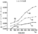
図9は、本発明の編組構造体により提供される改良された捩れ強度を示す概略図である。X軸40はスタイレットの基端の回転角度を示す。Y軸42はスタイレットの長さの全体を亙って伝達されたトルクの量をインチ−オンス単位にて表わす。曲線44は、ポリイミドスリーブと共にニチノール外側部材5を有するスタイレットの性能を示す。曲線46は、ポリイミドにて補強されたステンレス鋼平ワイヤー編組部にて形成された編組構造体18によって取り巻かれたニチノール外側部材5を有するスタイレットの性能を示す。曲線48は、ステンレス鋼平ワイヤー編組部にて形成された編組構造体18によって取り巻かれたニチノール外側部材5を有するスタイレットの性能を示す。グラフの点50、52で示すように、スタイレットの基端が180°回転すると、かかる構造体が存在しないスタイレットと比べて、編組ステンレス鋼構造体を有するスタイレットの25.4mm(1インチ)当たり2倍以上の回転力が伝達される。
【0047】
上述したように、本発明は、引張りワイヤー構造体を備えないスタイレットを含む任意の型式のスタイレットにて実施することができる。しかし、1つの好ましい実施の形態において、本発明は、末端先端を撓ませる引張りワイヤーを有するスタイレットに対して使用される。この撓みを実現するため多くの異なる機構が利用可能である。1つの実施の形態によれば、回転ノブを有するハンドルを利用して先端構造体に張力を与え、これにより撓ませることができる。
【0048】
図10は、本発明による編組構造体を備える撓み可能なスタイレットであって、スタイレットの末端を撓ませるために使用することのできる回転ノブハンドルを更に備える撓み可能なスタイレットの平面図である。撓み可能なスタイレット66は、主要なハンドル部分62及び回転体すなわち回転可能なノブ部分64が設けられたハンドル60を備える状態で図示されている。撓み可能なスタイレット66の末端部分は編組構造体65を備える状態で図示されているが、より多くの又は全ての撓み可能なスタイレット66を編組部とすることが可能であることが理解されよう。
【0049】
主要ハンドル部分62には、その基端に周溝63を設けることができる一方、回転体すなわち回転可能なノブ64には図示するように外側リブ又はギザギザ面を設けることができる。撓み可能なスタイレット66は回転体すなわち回転可能なノブ64内で基端リセス部65から出る。回転体すなわちノブ64が回転し又はノブ64がハンドル62に対し末端方向に前進すると、スタイレット66の末端部分は撓んで参照符号66Aで示した湾曲形態となる。
【0050】
撓み可能なスタイレット66は、外側部材及び内側緊張ワイヤー又は引張りワイヤーを採用する任意の既知の撓み可能なスタイレットの形態をとることができ、該内側緊張ワイヤー又は引張りワイヤーは、撓み可能なスタイレット66の末端に張力が加えられたとき、スタイレットの先端が湾曲して湾曲部66Aとなるようにする。これと代替的に、撓み可能なスタイレット66に代えて、例えば、その内容の全体を参考として引用し本明細書に含めた、ブッハバインダ(Buchbinder)に対して発行された米国特許第4,815,478号に開示されたような撓み可能なガイドワイヤーを使用してもよい。
【0051】
これらの色々なガイドワイヤー及びスタイレットの全てにおいて、撓み可能なスタイレット又はガイドワイヤーの基本構造は、弛緩した状態にてほぼ直線状の形態を示すステアリング可能なガイドワイヤーに対する外側部材から成っている。この構造体は、ガイドワイヤー又はスタイレットの末端部分に接続された内側引張りワイヤー又は緊張ワイヤーを更に備えており、該内側引張りワイヤー又は緊張ワイヤーは、ガイドワイヤー又はスタイレットの末端先端に張力が加えられたとき、ガイドワイヤー又はスタイレットの末端部分が湾曲形態を呈するように配置されている。
【0052】
図11は、心臓歩調とり導線70内に挿入された図1の撓み可能なスタイレットの平面図である。心臓歩調とり導線70はその基端に配置されたコネクタ組立体68を備えており、該コネクタは、典型的に、心臓歩調とり導線の場合に典型的であるようにコネクタピンを保持している。例えば、コネクタ組立体68の末端部分は、同様にその内容の全体を参考として引用し本明細書に含めた、ドーン(Doan)らに対して発行された米国特許第4,922,607号に開示されたようなIS−1コネクタ標準品に相応するものとすることができる。しかし、その双方の内容の全体を参考として引用し本明細書に含めた、ドーリング(Doring)に対して発行された米国特許第4,488,561号又はヘス(Hess)らに対して発行された米国特許第4,572,605号に開示されたようなその他のコネクタの形態を採用することもできる。
【0053】
歩調とり導線70の末端には、その内容の全体を参考として引用し本明細書に含めた、モリス(Morris)らに対して発行された米国特許第5,473,812号に開示された、心臓を刺激すべく心臓組織内にねじ込まれる固定のヘリカル電極72のような電極が配置されている。しかし、電極72に代えて任意のその他の型式の既知の歩調とり電極を使用し又はこれと代替的に、カルジオバージョン電極すなわち除細動電極のようなその他の型式の電極を電極72に追加し又は電極72に置換することができる。
【0054】
全体として、本発明の撓み可能なスタイレットにより撓ませる導線と共に採用可能である歩調とり及びカルジオバージョン電極の例は、ストークス(Stokes)らに対して発行された米国特許第5,282,844号、ストークスに対して発行された米国特許第4,506,680号、へランド(Helland)らに対して発行された米国特許第4,033,357号、カロック(Kallok)に対して発行された米国特許第4,727,877号、ホールマン(Holleman)らに対して発行された米国特許第5,115,818号、ラスク(Laske)らに対して発行された米国特許第5,728,149号に記載されたものを含み、これら米国特許の全てはその内容の全体を参考として引用し本明細書に含めてある。
【0055】
図12は、本発明と共に使用可能であるスタイレットシステムの1つの実施の形態の切欠き図である。この実施の形態は、その内容の全体を参考として引用し本明細書に含めた、グリーン(Greene)に対して発行された米国特許第6,027,462号に開示されたものと同様である。このシステムは部分的に分解したハンドル組立体110と共に図示されている。ハンドル112は、ハンドルの長さに亙って伸びる長手方向線にほぼ沿って共に接続された2つの成形プラスチック部品から製造される。2つのハンドル半体112Aの一方は、ノブ又は回転体114と共に図示され、その前の図面にて図示しない断面及び内部スライダ200を示す。
【0056】
ノブ14における内部の末端方向を向いたリセス部115は、この図面にて図示されており、また、撓み可能なスタイレット116に対する歪み除去部分として本来的に作用する十分な長さの寸法とされており、スタイレットがスライダ200から出る箇所にてスタイレットが折れたり又は曲がるのを防止する。リセス部115は、また、ハンドルに対して基端位置と末端位置との間を移動するとき、外科医が自分の手の位置を変更することを助け、また、コネクタピンの末端側のコネクタ組立体の部分がノブの末端に直ぐ隣接するようにすることも助ける。
【0057】
スライダ200は、全体として、ノブ114内の雌ねじ部204に係合する雄ねじ部202が設けられたロッドの形態をしている。スライダ200の基端には、図面には図示しない、成形ハンドル半体の相応する溝に係合するカラー206があり、スライダ200がハンドルに対して回転するのを防止する。このように、ノブ114がハンドルに対して回転すると、スライダ200は長手方向に移動するが、回転動作は行わない。
【0058】
撓み可能なスタイレット116の外管は、スライダ200に機械的に結合される一方、スタイレット116内の緊張ワイヤー208はハンドルに定着されている。このように、スライダ200がハンドル112Aに対して末端方向に移動すると、スタイレットの外管は緊張ワイヤー208に対して移動し、撓み可能なスタイレットに関する上記の色々な特許にて説明された仕方にて緊張ワイヤー208はスタイレットの先端に張力を加え且つスタイレットの先端を撓ませる。緊張ワイヤー208はハンドル内に固定状態に取り付けられた六角ナット212により長手方向に調節されるねじ付きロッド210に定着される。
【0059】
図示するように、ノブ114及びスライダ200はハンドルに対して1ユニットとして末端方向に摺動し、緊張ワイヤー208に張力を加え且つスタイレット216を撓ませる1つの代替的な機構を提供することができる。この機構によるスタイレットの撓みは、例えば、冠状静脈洞のような所望の位置まで導線を導入するのを容易にし又は導線を大静脈及び三尖弁を通じて進めるため、外科医が、極く短時間だけ且つ極めて迅速に湾曲させることを望む場合に便宜である。
【0060】
図示した実施の形態において、スライダには、埋込み可能な導線のコネクタピンを受け入れることのできる内側穴214が設けられている。この場合、穴214はコネクタピンよりも大きい直径とし、導線がスタイレット216に対して回転可能であるようにする必要がある。これと代替的に、穴214を省略し、コネクタピンがスライダ200の末端に単に隣接して位置するようにしてもよい。
【0061】
図13には、固定ヘリックスを有する型式の導線のコネクタピンが取り付けられた、本発明による取り付け部と共に、撓み可能なスタイレットハンドルの末端部分の切欠き図が図示されている。図示するように、撓み可能なスタイレットの制御ハンドルは、全体として、上記に引用したグリーンらの特許に記載され且つ図12に図示されたものと相応する。ハンドル112A、ノブ又は回転体114、撓み可能なスタイレット116及び緊張ワイヤー208は、図12に図示した同一番号の構成要素に相応する。この実施の形態のスライダ200Aは、外方に伸びるねじ部202Aの高さがスライダ200にて採用されるもの(図12)よりも多少低い点を除いて、スライダ200に相応する。撓み可能なスタイレットハンドル自体の作用は図12に関して上述したものと同一である。
【0062】
スタイレットハンドルに取り付けられた、本発明による取り付け部304も図示されている。取り付け部304はほぼ管状の部材314がそこから基端方向に伸びるほぼ円筒状のノブ316を備えている。管状部材314は、ノブすなわち回転体114の末端を向いたリセス部内に回転可能に取り付けられ且つ該リセス部内で長手方向に摺動可能である。取り付け部304の末端には、末端方向を向いた穴があり、該穴内に歩調とり導線312のコネクタピン310が挿入され且つねじ308により固定されている。導線312は定ヘリックスを有する型式の導線であると理解すべきであり、この場合、定ヘリックスはコネクタピン310の回転によって前進し、導線本体を回転させるか、又はヘリックスを導線本体に対して回転させる。
【0063】
管状ピン300を取り巻くブッシュ302が取り付け部304の基端方向に伸びる管状部材314内に配置される一方、該管状ピンは撓み可能なスタイレット116の周りに取り付けられている。ブッシュ302は管状部材314の内部に接着剤又はその他の方法で接合されており、管状ピン300に対して回転自在である。管状ピン300は、スライダ200Aの末端のリセス部214A内に取り付けられ且つ接着剤又はその他の方法によりその内部で摩擦を利用して固定されている。
【0064】
プラグ306は管状部材314の基端に取り付けられている。以下に説明するように、ピン300を設けることは、取り付け部304が撓み可能なスタイレットハンドルに対して可能な長手方向移動範囲を増大させ、これにより、長さの異なる導線と共に使用される組立体の可調節程度を向上させ且つ導線312の本体内のスタイレット116の位置を調節することを許容する。
【0065】
図14は、ハンドル組立体110及び取り付け部304の別の実施の形態の切欠き図であり、その内容の全体を参考として引用し本明細書に含めた、「ねじ込み導線を撓ませる方法及び装置(Method and Apparatus for Deflecting a Screw−In Lead)」についてガーデスキ(Gardeski)らが同日に出願した米国特許出願第09/659,797号、弁護士事件番号第P8455号に開示されたものと同様である。
【0066】
この図面において、図12、図13における相応する全ての構成要素は参照が容易であるように、前の図面12、13にて使用したものと同一の参照番号で表示してある。上述した実施の形態におけるように、この実施の形態は、ハンドルの長さに沿って伸びる長手方向線にほぼ沿って互いに接続された2つの成形プラスチック部品から成るハンドルを備えている。参照番号112Aとして図示された2つのハンドル半体の一方は、断面図で示したノブすなわち回転体114と、その前の図面に図示しない内部スライダ200と共に図示されている。
【0067】
その前の図12、13に図示したものと同様の図14に図示したハンドルの実施の形態は、取り付け部の別の実施の形態を含んでいる。上述した実施の形態におけるように、該取り付け部は、ハンドルの長さに沿って伸びる長手方向線にほぼ沿って互いに接続された2つの成形プラスチック部品から成っており、取り付け部304aの半体は図14に図示されている。図13に関して説明したのと同様の仕方にて、この取り付け部は、ほぼ管状部材314がそこから基端方向に伸びるほぼ円筒状ノブ316を備えている。管状部材314は、ノブすなわち回転体114の末端を向いたリセス部内で回転可能に取り付けられ且つ該リセス部内で長手方向にも摺動可能である。この実施の形態において、管状部材314は以下に更に説明する結合機構(図6に図示せず)を備えている。この結合機構は、ピン334内に形成された切欠き336の任意のものに対して堅固に配置し得るようにされている。このように、取り付け部304aは、ピン334の長さの少なくとも所定の部分に沿って所定の間隔で堅固に配置し直すことができる。
【0068】
この実施の形態において、取り付け部304aは、取り付け部304aに導線ピンを固定するため押釦型U字形リンクを使用する導線取り付け機構を更に備えている。図14には、歩調とり導線312のコネクタピン310を取り付け部に結合し、以下に更に説明するこの押釦340の断面図が図示されている。これは、図13のねじ308の1つの代替的な結合機構である。図14の実施の形態は、図13のねじ308と比較して、結合機構を係合させ且つ非係合状態にさせるには片手の動作のみで済むという有利な点を提供する。
【0069】
図15は、押釦340を更に備える、図14の実施の形態の取り付け部の第1の半体304a及び第2の半体304bのそれぞれ斜視図である。押釦340は、取り付け半体304bのリセス部338b内で摺動可能に係合し且つ図15の破線で示すように取り付け半体が互いに結合されたとき、取り付け半体304aのリセス部338a(この図面にて図示せず)に更に係合し得るようにされている。押釦は、押釦の基端面から垂直に突き出す状態で示した回り止めピン347によってリセス部338bからの脱落が防止される。リセス部内に挿入されたとき、押釦はほぼ、第1のルーズな位置又は第2の係止位置の何れかにある。
【0070】
取り付け部半体の各々は、取り付け部半体304a、304bの円筒状ノブ316の末端面に切欠き領域342a、342bをそれぞれ更に備えている。この切欠き領域は埋込み可能な導線346の導線コネクタピン344の配置を受け入れる。押釦がルーズな位置にあるとき、導線346のコネクタピン344をこの切欠き領域内に容易に挿入することができる。一度び導線コネクタがこのように配置されたならば、押釦は係止位置にスナップ止めし、押釦340はコネクタピン344を開口345の一端内に捕捉することができる。このことは、埋込み可能な導線346を取り付け部に対する堅固な位置に固定することになる。次に、円筒状ノブ316を回すと導線本体の全体が回転し、隣接する組織内で導線本体の末端に保持することのできるヘリカルねじを容易に固定することを許容する。この押釦機構について以下に更に説明する。
【0071】
図15には、ピン334内に設けられた切欠き336に結合するように設けられる結合機構348が更に図示されている。1つの実施の形態において、この結合機構は、取り付け部半体304a、304bの一方又はその双方に含めることのできる突出部348である。この突出部は切欠き336の任意の内部に装着し、取り付け部をピン334に沿った規則的な間隔で選択的に配置することを許容し得るようにされている。上述した実施の形態の改変例は本発明の範囲内で許容可能であり、かかる改変の可能性は特許請求の範囲に関連して理解すべきである。
【図面の簡単な説明】
【図1】
本発明により使用することのできる1例としてのスタイレットの概略図。
【図2】
本発明と共に採用可能であるスタイレットの第2の実施の形態の概略図。
【図3】
図1又は図2の何れかに図示したスタイレットの末端先端の分解斜視図。
【図4】
4Aは、編組構造体を含むスタイレットの末端先端部分の斜視図。
4Bは、編組構造体を含むスタイレットの末端先端部分の長手方向断面図。
【図5】
管状部材の末端部分上に設けられた編組構造体を示す斜視図。
【図6】
外側機構の長さに亙って設けられた編組構造体を示す斜視図。
【図7】
7Aは、平金属から形成された編組構造体を有する、図6の部分A−Aにて示した本発明のスタイレットの断面図。7Bは、平金属から形成された編組構造体を有する、図6の部分B−Bにて示した本発明のスタイレットの断面図。
【図8】
8Aは、ポリイミドにて補強した平金属から形成された編組構造体を有する、図6の部分A−Aにて示した本発明のスタイレットの断面図。8Bは、ポリイミドにて補強した平金属から形成された編組構造体を有する、図6の部分B−Bにて示した本発明のスタイレットの断面図。8Cは、スタイレットの外側部材5の内部空間内に配置された編組構造体を有する、部分A−Aにて示した本発明のスタイレットの断面図である。
【図9】
本発明の編組構造体により提供される改良された捩れ強度を示す概略図。
【図10】
スタイレットの末端先端を撓ませるべく使用可能な回転ノブハンドルを更に備える、本発明による編組構造体を有する撓み可能なスタイレットの平面図。
【図11】
心臓歩調とり導線内に挿入された図1の撓み可能なスタイレットの平面図。
【図12】
本発明と共に使用可能なスタイレットシステムの1つの実施の形態の切欠き図。
【図13】
固定ヘリックスを有する型式の導線のコネクタピンが取り付けられる、本発明による取り付け部と共に撓み可能なスタイレットハンドルの末端部分の切欠き図である。
【図14】
上記の図面に図示したようなハンドル組立体及び取り付け部の別の実施の形態の切欠き図である。
【図15】
押釦U字形リンクを更に備える、図14の実施の形態の取り付け部の第1及び第2の半体の斜視図である。[0001]
BACKGROUND OF THE INVENTION
The present invention relates to a wire guide or stylet assembly for introducing a pacing or defibrillation lead and a medical catheter to a desired location within a patient's body. In particular, the present invention relates to a steerable stylet assembly that provides a desired kinetic curvature to the distal portion of the catheter or lead during introduction. Such curvature is required to guide the catheter or lead through the patient's vasculature to a desired location in the heart. The present invention uses a braided flat wire wrapped around a tubular member that allows the surgeon user to add increased torsional transmission strength to the stylet via a handle provided with a rotary knob. To achieve and maintain the desired curvature for the conductor or catheter.
[0002]
Generally speaking, pacing and defibrillation leads and catheters are extremely flexible throughout their length to flex with heart movements or contractions and other body or muscle movements. . Such flexibility prevents the conductor body from breaking due to accumulated stress over time. However, as a result, implantable pacing and defibrillation leads and catheters are often too flexible to advance through the venous system to a desired internal location within the patient's cardiovascular system. To assist in the placement of such devices, a thin, reinforced stylet is inserted into the lumen of a lead or steerable catheter to guide navigation through the venous system and into the patient's heart, such as the coronary sinus. Ensure proper placement at the desired location or desired location within the vessel.
[0003]
The thin wire is inserted into the lumen found at the lead connector pin or into the proximal opening in the catheter's accessory (secondary) lumen and extends down the length of the device. . The stylet reinforces the entire assembly and allows the surgeon to bend at the distal end prior to placement within the lumen to provide a bend or curve to the lead or catheter. This curved distal portion facilitates the movement of the distal tip of the lead through the venous system and into a desired location in the patient's heart or into other blood vessels in the cardiovascular system.
[0004]
Many different types of stylets are available to help steer a catheter or lead. For example, some stylets must be given a desired shape prior to inserting the stylet into a wire or catheter. Optionally, when the surgeon directs the distal tip of the lead or catheter to the desired position, it may be necessary to withdraw the stylet and insert a new stylet with a different curvature. This process of replacing a new stylet with a different curvature can be used whenever the wire encounters a new obstacle to advance.
[0005]
However, this technique has several disadvantages. For example, repeated insertion and withdrawal of the stylet can soil the lumen of the lead with blood. This is undesirable because the dried blood will form a thrombus and clog the stylet in the wire, making removal of the stylet difficult and possibly impossible, thereby rendering the wire unusable. Further, continuing to insert and withdraw and replace with other stylets is time consuming and can damage the leads, blood vessels, or both.
[0006]
To avoid repeated withdrawal and reintroduction of the stylet, U.S. Patent No. 4,381, issued to Dutcher, which is incorporated herein by reference in its entirety. Other stylet styles have been proposed, including those proposed in U.S. Pat. No. 013 and U.S. Pat. No. 4,677,990 issued to Neubauer. A further example of a steerable stylet is disclosed in U.S. Patent No. 4,846,175, assigned to Frimberger.
[0007]
More recently, two alternative mechanisms have been proposed to make steerable stylets more useful. A first mechanism is proposed in U.S. Patent No. 5,396,902 issued to Brennan, which is hereby incorporated by reference in its entirety. U.S. Pat. No. 5,396,902 discloses an operating handle connected to the proximal end of a slotted tubular member disposed at the distal end of a stylet via a tension (or tension) wire during placement in the body. It is disclosed to use a steerable stylet that can be deflected and curved in a lead via.
[0008]
The tension applied to the puller wire causes the distal end of the stylet to flex and bend to meet the surgeon's requirements during placement of the lead. A second mechanism is described in US Pat. No. 6,027,462, issued to Greene, which is incorporated by reference in its entirety. U.S. Patent No. 6,027,462 discloses a handle that uses a rotating knob to deflect a tubular member, thereby providing a bend for the stylet and intracardiac lead assembly.
[0009]
The above examples of stylet embodiments describe various mechanisms utilized to facilitate distal deflection. Material selection is important in order to further facilitate tip deflection. In one embodiment, the stylet can be made from a material that has very high elasticity. For example, a superelastic nickel titanium alloy (nitinol) can be used for this purpose. By employing a very elastic material, the stylet tip can withstand large bending deflections without breaking the tip.
[0010]
As described above, the deflection of the stylet tip provides one mechanism for steering a lead or catheter through vascular tissue during deployment. Another mechanism involves rotating the end of the stylet. Once a bend is introduced into the wire or catheter tip via the bent stylet, it is often necessary to rotate the curved tip when the curved tip is guided to the required position. . For optimality, rotating the stylet proximal end by a predetermined amount results in the stylet end rotating by an equal amount. Such a one-to-one angular excursion over the length of the stylet is desirable but not possible.
[0011]
All materials used in the manufacture of stylets and guidewires produce a significant degree of twist when torque is applied to one end. This is especially true in the case of highly elastic metals such as superelastic nitinol, which is generally desired to be used to achieve high stylet tip deflection. This is also especially true for small diameter elongated bodies such as stylets or guidewires, since the torsional strength of the cylindrical body is proportional to three times the diameter of the stylet or guidewire.
[0012]
Thus, the use of nitinol and other materials, such as stainless steel, results in a stylet having a very flexible tip, but this technique is not suitable for rotational or angular excursions over the length of the stylet. Undesirably results, such as providing a device that is unable to transmit the signal down relatively. This problem is exacerbated by the increasingly smaller stylet and guidewire dimensions, as is the recent trend. Therefore, there is a need for an improved system that transmits rotational force throughout the length of a stylet or guidewire and further enhances the steerability of the lead or catheter body.
[0013]
Summary of the Invention
SUMMARY OF THE INVENTION The present invention is directed to an improved type of steerable guidewire or stylet having a braided structure that provides increased torsional strength to the stylet. The invention can be practiced with any type of stylet. In one embodiment, the stylet comprises an elongated tubular member having a pull wire located within the tubular member. The end of the puller wire is anchored to the end of the tubular member. One or more apertures may be provided near the distal end of the tubular member generally disposed within an elongated region located parallel to the axis of the tubular member. The one or more openings provide a preferential bending direction for the tubular member when tension is applied to the proximal end of the puller wire. In one embodiment, one or more of these openings comprises one elongated slot. The deflection ability of the stylet is improved by forming the tubular member from nitinol or another highly elastic metal.
[0014]
As mentioned above, the braided structure holds the puller wire within the slotted tubular member. The braid can optionally be formed of a metal such as a stainless steel flat wire that can be reinforced with polyimide. The braid can be provided along the entire length of the guidewire or stylet or, optionally, available only at the distal tip. The braid greatly improves the torsional strength of the stylet so that the rotational force applied to the proximal end of the guidewire is transmitted to the distal end. This increase in torsional strength is achieved without any substantial reduction in the deflection capability of the stylet's distal tip.
[0015]
In one embodiment, the stylet or guidewire of the present invention utilizes a handle similar to that disclosed in US Pat. No. 6,027,462. This handle is provided with a rotation knob and an inner slider member. The knob and slider members slide distally relative to the handle and provide a mechanism for quickly forming a bend in the stylet or guidewire. This is particularly beneficial when, for example, a bend is needed only temporarily to facilitate insertion into the desired vessel, such as the coronary sinus, along with the deflection of the stylet tip. . Alternatively, the knob may be rotated for greater deflection at the distal stylet tip. The handle provides a flexure mechanism with a minimal number of moving parts, and the flexure mechanism is positioned to facilitate easy control of the degree of curvature provided by the stylet or guidewire using only one hand. ing.
[0016]
Another embodiment of a handle that can be used with the present invention is "Method and Apparatus for Deflection of Threaded Leads," filed on the same date as the present application and incorporated herein by reference in its entirety. Method and Apparatus for Defecting a Screw-In Lead), and is shown and described in co-pending attorney case number P8455. The handle structure includes a deflectable wire extension tool that connects to a wire body, particularly an extendable-retractable wire. The disclosed system adapts the length of the lead to fit the stylet and further enhances the ease of flexing the stylet tip.
[0017]
DESCRIPTION OF THE PREFERRED EMBODIMENTS
FIG. 1 is a schematic diagram of an example stylet 2 that can be employed in accordance with the present invention. The stylet includes a handle 4, which may be one of the embodiments described below, i.e., any other type of handle. The stylet 2 can be tubular and has an outer member 5 consisting of a proximal portion 6 and a distal portion 8 connected at a seam 10. The proximal portion 6 can be formed of a first metal material such as stainless steel or polyimide. End portion 8 may be formed of a second material having superelastic properties, such as superelastic nickel titanium alloy (Nitinol) or another similar metal. By using a superelastic alloy to form the distal tip, a large flexing force can be applied to the tip without breaking.
[0018]
In the embodiment of FIG. 1, the superelastic material is used only at the distal end 8, where most of the stylet deflection occurs. Different materials are employed to form other parts of the stylet body. This design choice has the advantage of minimizing the effects of poor torsional strength exhibited by the superelastic material at the distal tip. It is desirable to use a different type of material, such as stainless steel, over the large proximal portion of the stylet, as this type of material does not transfer torque efficiently. In addition to exhibiting higher torsional strength, harder materials such as stainless steel are more "pushable", reducing the degree of difficulty in pushing the stylet through vascular tissue.
[0019]
The end portion 8 has a slot 12. This slot provides one preferential bending direction for the distal tip portion 8 of the stylet 2. When flexed, the distal tip of the stylet bends in the direction of the slot and the slotted edge defines an inner curve of the flexed distal tip. Other types of stylets can be used with the present invention, including stylets having multiple openings positioned along one side of the stylet body so as to define a preferred bending direction.
[0020]
The stylet of FIG. 1 further includes a pull wire 14 inside the outer member 5. The puller wire extends along the entire length of the stylet and is connected to the handle 4. An embodiment of this handle interconnection is described below. The pull wire can be formed of steel, nitinol or other suitable materials such as Dacron, ultra high molecular weight polyethylene (UHMWPE), or polyetheretherketone (PEEK) single fibers. The puller wire is also attached to the end of the outer member 5 by a crimp sleeve 15 or the like, which can be formed of stainless steel crimped to the end of the outer member 5. As a result of the tension applied to the puller wire at the handle 4, the outer member 5 flexes in the area of the slot 12, as described above.
[0021]
FIG. 2 is a schematic diagram of a second embodiment of a stylet that can be employed with the present invention. This stylet 2A includes many of the elements shown in FIG. 1, including handle 4, outer member 5, slot 12, puller wire 14, and crimp sleeve 15. However, the outer member 5 of the stylet 2A does not include a distal portion and a proximal portion that are connected at the seam as shown at seam 10 in FIG. In this embodiment, both the distal and proximal ends of outer member 5 are formed of the same material, which can be a superelastic material such as Nitinol or a different material such as stainless steel or polyimide.
[0022]
The embodiment of FIG. 2 has advantages over the embodiment of FIG. 1 without the seam 10 as shown in FIG. Forming this seam requires more complex manufacturing steps than would be necessary to form the stylet from only one material. However, this embodiment does not provide the advantage of having a first material having increased torsional strength at the proximal end and a second material having increased flexing capability at the distal end.
[0023]
FIG. 3 is an exploded perspective view of the distal end of the stylet shown in either FIG. 1 or FIG. This figure includes an outer member 5, a pull wire 14, a crimp sleeve 15, and a slot 12. In one embodiment, the width W 18 of the slot 12 is greater than the diameter D 19 of the puller wire 14. This prevents the puller wire from cutting into slot 12. In other embodiments, the width 18 of the slot 12 can be smaller than the diameter 19 of the puller wire 14.
[0024]
FIG. 3 further illustrates a crimp recess 16 included in the crimp sleeve 15 to connect the crimp sleeve 15 to the puller wire 14. The gap 17 between the crimp sleeve 15 and the outer member 5 is relatively small, so that the tension applied to the proximal end of the puller wire 14 causes the crimp sleeve 15 to come into contact with the outer member 5, whereby the outer member 5 A bending force.
[0025]
As mentioned above, many materials do not exhibit sufficient torsional strength. This is especially true for superelastic metals such as Nitinol. To increase the torsional strength of the outer member 5, a braided structure can be used to form a sheath around the tube. The braided structure is made of a material such as stainless steel mold 304 which has a higher modulus of elasticity than the slotted outer member. A braided component provides flexibility (flexibility), while a large modulus of elasticity provides optimal torsional strength.
[0026]
FIG. 4A is a perspective view of a distal end portion of the stylet 2 or 2A including the braided structure 18. FIG. The braided structure serves to hold the puller wire 14 within the slotted outer member 5 when tension is applied to the proximal end of the puller wire. Further, the braided structure greatly enhances the torsional strength of the stylet so that the rotational force applied to the distal end can be transmitted to the distal end. This increased torsional strength is provided without any substantial reduction in the deflection capability of the stylet's distal tip.
[0027]
The braided structure 18 is connected to the outer member 5 at at least one location. This connection can be realized by resistance welding or laser welding. Alternatively, the braided structure may be soldered using silver solder. In yet another embodiment, the connection can be made using a brazing method or a crimp ring. Also, an adhesive bonding method may be used to connect the braided structure to the outer member 5.
[0028]
After connecting the braided structure 18 to the outer member 5, both the braided structure and the outer member 5 can be pulled out through a die to remove slack and achieve a final constant diameter.
FIG. 4B is a longitudinal cross-sectional view of a distal end portion of the stylet 2 or 2A including the braided structure 18.
[0029]
The braided structure can be formed from a wide variety of materials. In one embodiment, the braid can be formed of a stainless steel flat wire alone or a metal such as a stainless steel flat wire reinforced with polyimide. For example, a stainless steel flat wire type T304V can be used. Preferably, the metal utilized for the braid has an ultimate tensile strength (UTS) in the range of 200,000 to 350,000 lbs / in 2.
[0030]
Another material that can be used for the braid is a precipitation hardened stainless steel such as PH17-7 or custom 450 or 455. This type of material is relatively flexible in the annealed condition, and is therefore easier to braid and terminate than high temper stainless steel type 304 strip steel wire. For example, the custom 450 can be easily connected by welding the wires at the intersections of the wires (pick intersections). The braided structure can then be aged and hardened by a single heat treatment to achieve a substantially higher yield strength than type 304 stainless steel.
[0031]
Yet another material that can be used to form the braid is molybdenum having a modulus of elasticity of about 50,000,000 lbs / in 2. Molybdenum is significantly more durable than stainless steel with a modulus of elasticity of about 29,000,000 lbs / in 2. Molybdenum is typically rolled into a flat stock material while maintaining good surface finish.
[0032]
Another alternative embodiment is provided using a round wire instead of a strip wire forming a braid. In this embodiment, the diameter is. 508 mm (0.020 inch) to. Suitable for a 635 mm (0.025 inch) steerable stylet. The use of round wire has the disadvantage of increasing the stylet diameter. However, in this embodiment, since the degree of surface contact between the wires at the pick intersection of the wires is small, the braided portion can be more flexible.
[0033]
The braided structure can be woven in many different types of patterns. FIG. 4 illustrates a “upper two times, lower two times (two-over, two-under)” braided pattern.
[0034]
In one embodiment, the braided structure has a thickness. 0127 mm (.0005 inches), width. It is 0635 mm (.0025 inches) and is woven from strip steel wire having a pick count of 100 to 160. The pick count is a measure of the tightness of the weave of the braided structure. The pick count is to count the number of strands in the first and second directions that intersect within a 1 inch (25.4 mm) line drawn longitudinally along the stylet. Is calculated by For example, assuming that arrow 24 measures a 25.4 mm (1 inch) portion of the stylet, the pick count would be "3". In an alternative, the tightness of the weave can be described using the braid angle, which is the included angle measured longitudinally between the two intersecting wires.
[0035]
It is important to maintain a pick count that is not large enough that the deflection capability is significantly affected. For example, FIG. 4 illustrates a weaving state in which a space such as the space 26 remains between adjacent strands such as the space 26. Such a space is necessary to allow the strand to move slightly when the distal end of the outer member 5 bends. If the strands are tightly woven so that no space remains, the wire 14 must be pulled with greater force to flex the tip. This makes the stylet more difficult to use.
[0036]
The type of braided metal used to form the present invention is available in many different dimensions. According to one embodiment of the present invention, a thickness. 0127 mm (.0005 inches) and width. A flat braid of 0635 mm (.0025 inch) T304V stainless steel can be used. In this embodiment, a braided structure having a pick count of 124 picks per inch can be used. In another embodiment, the thickness. 0178 mm (.0007 inches) and width. A flat braid of 127 mm (0.005 inch) type T304V stainless steel can be used.
[0037]
In this embodiment, a braided structure having a pick count of 50 picks per inch can be used. Preferably, the steel strip wire is. It shall have a thickness of 0254 mm (.0010 inches) or less, and the width shall be limited by the braiding process. In general,. Braiding with a width of 254 mm (0.010 inches) or more at these diameters is extremely difficult.
[0038]
The present invention provides a stylet with a minimum diameter. The reason is that it is possible to use a very small outer member 5 while keeping the stylet with an acceptable torsional strength. In one embodiment of the present invention, the stylet including the braided structure 18 is a. 635 mm (.025 inch) or less, and generally 381 mm (.015 inch) to. It has a diameter in the range of 635 mm (0.025 inch). Of course, larger stylets can also take advantage of the present invention to improve torsional rigidity.
[0039]
In one embodiment of the present invention, the braided structure can extend from the handle 4 to the distal tip of the outer member 5. In another embodiment, the braided structure can be provided only on the distal portion 8 of the outer member 5, as shown in FIG. If the braided structure is provided over the entire length of the outer member 5, the braided structure need not end at an intermediate position on the outer member 5. This is desirable because this type of connection requires more complicated manufacturing steps to be realized. Furthermore, the braided structure over the entire length provides increased bending flexibility in combination with increased torsional strength over the entire length of the outer member 5. This is beneficial regardless of whether stainless steel, nitinol or polyimide is used at the proximal end of the outer member 5 or over its entire length.
[0040]
FIG. 5 is a perspective view showing the braided structure 18 provided on the distal portion 8 of the outer member 5. FIG. 6 is a perspective view showing the braided structure 18 provided over the entire length of the outer member 5. As described above, in one embodiment, the braided structure 18 is formed from a flat metal wire structure. In another embodiment, the braided structure is reinforced with a high performance polyimide or rigid polyamide (nylon) material, such as those commercially available from Phelps Dodge, Inc. of Trenton, Georgia. be able to. For example, a reinforced braided structure can be formed by immersing a tubular core in polyimide.
[0041]
After the polyimide has cured, the braided structure is woven around the dipped core. Finally, the dipped core and braided structure are dipped again into the polyimide. After the polyimide second coating has cured, the core structure is removed. The braided tubular structure slides over the stylet outer member 5 and is adhesively bonded to the stylet outer member 5 by an epoxy adhesive. The above immersion step is generally performed as a continuous step from reel to reel.
[0042]
FIG. 7A is a cross-sectional view of the stylet of the present invention at a position A in FIG. This cross-section shows the slot 12 and the braided structure 18 at the braid intersection. In one embodiment, the outer diameter D1 of the outer member 5 is. The inner diameter D2 of the outer member 5 is 3454 mm (0.0136 inch). 2032 mm (.0080 inches), and the width W1 of the slot is. It is 1778 mm (.0070 inches). The ribbon wire included in the braided structure 18 has a thickness of. 0127 mm (.0005 inches) and width. It can be 0635 mm (.0025 inches).
[0043]
FIG. 7B is a cross-sectional view of the stylet of the present invention at position B in FIG. FIG. 8A is a cross-sectional view of the stylet of the present invention having a braided structure formed of a flat metal reinforced with a polyimide sheath 34 at a position A in FIG. In one embodiment, the stylet has dimensions similar to those described with respect to FIG. In this embodiment, the diameter D3 of the polyimide sheath 34 is. 4064 mm (0.0160 inch).
[0044]
FIG. 8B is a cross-sectional view of the stylet of the present invention having a braided structure formed of a flat metal reinforced at position B in FIG.
In the above embodiment, the braided structure 18 is shown outside the outer member 5. In one alternative embodiment, the braided structure can be connected to the inner surface of the outer member 5. This embodiment is particularly advantageous if the diameter of the puller wire 14 is equal to or greater than the slot width W1 (FIG. 8A).
[0045]
FIG. 8C is a cross-sectional view of the stylet of the present invention having a braided structure disposed in the inner space of the outer member 5. This figure further illustrates a slot 12 having a width W2 smaller than the diameter D4 of the puller wire 14, but this is not a requirement. The braided structure 18 is arranged in the outer member 5. Although this embodiment further illustrates that a round wire is inserted into the braided structure 18, a steel strip wire can be used as an alternative. The braided structure can also include a polyimide sheath, as shown in FIGS. 8A and 8B. As mentioned above, the present invention allows the rotational force applied to the proximal end of the tubular structure to be more efficiently transmitted to the distal end of the tubular structure.
[0046]
FIG. 9 is a schematic diagram illustrating the improved torsional strength provided by the braided structure of the present invention. The X axis 40 indicates the rotation angle of the base end of the stylet. Y-axis 42 represents the amount of torque transmitted in inches-ounces over the length of the stylet. Curve 44 shows the performance of a stylet having a Nitinol outer member 5 with a polyimide sleeve. Curve 46 shows the performance of a stylet having a Nitinol outer member 5 surrounded by a braided structure 18 formed of a stainless steel flat wire braid reinforced with polyimide. Curve 48 illustrates the performance of a stylet having a Nitinol outer member 5 surrounded by a braided structure 18 formed of a stainless steel flat wire braid. As shown by points 50 and 52 in the graph, a 180 ° rotation of the proximal end of the stylet would result in a 25.4 mm (1 inch) increase in the stylet with the braided stainless steel structure compared to a stylet without such a structure. ) Is transmitted twice or more.
[0047]
As mentioned above, the present invention can be implemented with any type of stylet, including stylets without a pull wire structure. However, in one preferred embodiment, the present invention is used for a stylet having a pull wire that flexes the distal tip. Many different mechanisms are available to achieve this deflection. According to one embodiment, the tip structure can be tensioned using a handle having a rotating knob, and thereby flexed.
[0048]
FIG. 10 is a plan view of a deflectable stylet comprising a braided structure according to the present invention, the deflectable stylet further comprising a rotary knob handle that can be used to flex the distal end of the stylet. is there. The deflectable stylet 66 is shown with a handle 60 provided with a main handle portion 62 and a rotating or rotatable knob portion 64. Although the distal portion of the deflectable stylet 66 is shown with a braided structure 65, it is understood that more or all of the deflectable stylet 66 can be a braid. Like.
[0049]
The main handle portion 62 can be provided with a circumferential groove 63 at its proximal end, while the rotator or rotatable knob 64 can be provided with outer ribs or knurls as shown. The deflectable stylet 66 exits the proximal recess 65 in a rotating body or rotatable knob 64. As the rotator or knob 64 rotates or the knob 64 advances distally with respect to the handle 62, the distal portion of the stylet 66 flexes into a curved configuration, indicated by reference numeral 66A.
[0050]
The deflectable stylet 66 may take the form of any known deflectable stylet employing an outer member and an inner tensioning or pulling wire, wherein the inner tensioning or pulling wire comprises a deflectable stylet. When tension is applied to the distal end of the let 66, the tip of the stylet bends into a curved portion 66A. Alternatively, instead of the deflectable stylet 66, for example, U.S. Pat. No. 4,815, issued to Buchbinder, which is hereby incorporated by reference in its entirety. , 478, may be used.
[0051]
In all of these various guidewires and stylets, the basic structure of the deflectable stylet or guidewire consists of an outer member for a steerable guidewire that exhibits a substantially linear configuration in a relaxed state. . The structure further comprises an inner puller or tensioner wire connected to a distal portion of the guidewire or stylet, the inner puller or tensioner tensioning the distal tip of the guidewire or stylet. When deployed, the distal portion of the guidewire or stylet is arranged to assume a curved configuration.
[0052]
FIG. 11 is a plan view of the deflectable stylet of FIG. 1 inserted into a heart pacing lead 70. The heart pacing lead 70 has a connector assembly 68 located at its proximal end, which typically holds the connector pins as is typical for a heart pacing lead. . For example, the distal portion of connector assembly 68 is disclosed in U.S. Pat. No. 4,922,607 issued to Doan et al., Which is also incorporated herein by reference in its entirety. It may correspond to a standard IS-1 connector as disclosed. However, both U.S. Pat. No. 4,488,561 issued to Doring or Hess et al., Both of which are incorporated herein by reference in their entireties. Other connector configurations, such as those disclosed in U.S. Pat. No. 4,572,605, may also be employed.
[0053]
At the end of the pacing lead 70, disclosed in US Pat. No. 5,473,812 issued to Morris et al., Which is hereby incorporated by reference in its entirety, An electrode, such as a fixed helical electrode 72, is threaded into the heart tissue to stimulate the heart. However, any other type of known pacing electrode may be used in place of electrode 72 or, alternatively, other types of electrodes such as cardioversion or defibrillation electrodes may be added to electrode 72. Or the electrode 72 can be used.
[0054]
Overall, examples of pacing and cardioversion electrodes that can be employed with the flexure stylet of the present invention are described in US Pat. No. 5,282,844 issued to Stokes et al. No. 4,506,680 issued to Stokes; U.S. Pat. No. 4,033,357 issued to Helland et al .; issued to Kallok. U.S. Pat. No. 4,727,877, U.S. Pat. No. 5,115,818 issued to Holleman et al., And U.S. Pat. No. 5,728 issued to Laske et al. 149, all of which are incorporated herein by reference in their entirety.
[0055]
FIG. 12 is a cut-away view of one embodiment of a stylet system that can be used with the present invention. This embodiment is similar to that disclosed in US Pat. No. 6,027,462 issued to Green, which is incorporated by reference herein in its entirety. . This system is shown with the handle assembly 110 partially exploded. Handle 112 is manufactured from two molded plastic parts connected together substantially along a longitudinal line extending the length of the handle. One of the two handle halves 112A is shown with a knob or rotator 114, showing a cross-section and an internal slider 200 not shown in the previous figures.
[0056]
The interior distally facing recess 115 in knob 14 is shown in this drawing and is of sufficient length to inherently act as a strain relief for deflectable stylet 116. This prevents the stylet from breaking or bending where the stylet exits the slider 200. Recess 115 also helps the surgeon reposition his or her hand as it moves between a proximal position and a distal position with respect to the handle, and also provides a connector assembly distal to the connector pins. It also helps to make the part immediately adjacent the end of the knob.
[0057]
Slider 200 is generally in the form of a rod having a male thread 202 that engages a female thread 204 in knob 114. At the proximal end of the slider 200 is a collar 206, not shown, that engages a corresponding groove in the molded handle half to prevent the slider 200 from rotating relative to the handle. Thus, when the knob 114 rotates with respect to the handle, the slider 200 moves in the longitudinal direction, but does not perform a rotating operation.
[0058]
The outer tube of the deflectable stylet 116 is mechanically coupled to the slider 200, while the tensioning wires 208 within the stylet 116 are anchored to the handle. Thus, as the slider 200 moves distally with respect to the handle 112A, the outer tube of the stylet moves with respect to the tensioning wire 208, in the manner described in the various patents relating to the deflectable stylet. The tension wire 208 applies tension to the tip of the stylet and deflects the tip of the stylet. The tensioning wire 208 is secured to a threaded rod 210 that is longitudinally adjusted by a hex nut 212 fixedly mounted within the handle.
[0059]
As shown, knob 114 and slider 200 slide distally as a unit with respect to the handle, providing one alternative mechanism for tensioning tension wire 208 and deflecting stylet 216. it can. The deflection of the stylet by this mechanism facilitates the introduction of the lead to the desired location, e.g., the coronary sinus, or advances the lead through the vena cava and tricuspid valve so that the surgeon can only And it is convenient when it is desired to bend very quickly.
[0060]
In the illustrated embodiment, the slider is provided with an inner hole 214 that can receive a connector pin of an implantable lead. In this case, the hole 214 must be larger in diameter than the connector pin so that the conductor can rotate with respect to the stylet 216. Alternatively, the hole 214 may be omitted and the connector pin may be located just adjacent to the end of the slider 200.
[0061]
FIG. 13 shows a cut-away view of the distal end of a deflectable stylet handle with an attachment according to the present invention with a connector pin of the type conductor having a fixed helix attached. As shown, the control handle of the deflectable stylet generally corresponds to that described in the Green et al. Patent cited above and illustrated in FIG. The handle 112A, knob or rotator 114, deflectable stylet 116 and tensioning wire 208 correspond to the same numbered components shown in FIG. The slider 200A of this embodiment corresponds to the slider 200 except that the height of the outwardly extending screw portion 202A is slightly lower than that employed in the slider 200 (FIG. 12). The operation of the deflectable stylet handle itself is the same as described above with respect to FIG.
[0062]
Also shown is an attachment 304 according to the present invention attached to the stylet handle. The mounting portion 304 includes a generally cylindrical knob 316 from which a generally tubular member 314 extends proximally. Tubular member 314 is rotatably mounted and longitudinally slidable within a recess toward the distal end of knob or rotator 114. The distal end of the mounting portion 304 has a distally facing hole into which the connector pin 310 of the lead 312 is inserted and secured with a screw 308. It should be understood that the conductor 312 is a type of conductor having a constant helix, wherein the constant helix is advanced by rotation of the connector pin 310 to rotate the conductor body or to rotate the helix relative to the conductor body. Let it.
[0063]
A bush 302 surrounding the tubular pin 300 is disposed within a tubular member 314 extending proximally of the mounting portion 304, while the tubular pin is mounted around a deflectable stylet 116. Bush 302 is adhesively or otherwise joined to the interior of tubular member 314 and is rotatable with respect to tubular pin 300. The tubular pin 300 is mounted in a recess 214A at the distal end of the slider 200A and is frictionally secured therein by an adhesive or other method.
[0064]
Plug 306 is attached to the proximal end of tubular member 314. As described below, the provision of pins 300 increases the range of longitudinal movement that mounting portion 304 can provide for the deflectable stylet handle, thereby reducing the set of wires used with conductors of different lengths. This increases the degree of adjustability of the volume and allows the position of the stylet 116 within the body of the conductor 312 to be adjusted.
[0065]
FIG. 14 is a cutaway view of another embodiment of the handle assembly 110 and the mounting portion 304, which is incorporated herein by reference in its entirety. (Method and Apparatus for Defecting a Screw-In Lead) is similar to that disclosed in U.S. Patent Application Serial No. 09 / 659,797 filed by Gardeski et al. .
[0066]
In this drawing, all corresponding components in FIGS. 12 and 13 are designated by the same reference numerals as used in the previous drawings 12 and 13 for ease of reference. As in the embodiment described above, this embodiment comprises a handle consisting of two molded plastic parts connected to one another substantially along a longitudinal line extending along the length of the handle. One of the two handle halves, shown as reference numeral 112A, is shown with a knob or rotator 114 shown in cross-section and an internal slider 200 not shown in the preceding drawings.
[0067]
The embodiment of the handle shown in FIG. 14 similar to that shown in FIGS. 12 and 13 before that includes another embodiment of the mounting portion. As in the embodiment described above, the mounting part consists of two molded plastic parts connected to one another substantially along a longitudinal line extending along the length of the handle, the half of the mounting part 304a being This is illustrated in FIG. In a manner similar to that described with respect to FIG. 13, the mount includes a generally cylindrical knob 316 from which a generally tubular member 314 extends proximally. Tubular member 314 is rotatably mounted in a recess facing the knob or rotator 114 and is also slidable longitudinally within the recess. In this embodiment, the tubular member 314 includes a coupling mechanism (not shown in FIG. 6) which is further described below. The coupling mechanism is adapted to be securely positioned with respect to any of the notches 336 formed in the pins 334. In this manner, the mounting portions 304a can be rigidly repositioned at predetermined intervals along at least a predetermined portion of the length of the pin 334.
[0068]
In this embodiment, the mounting portion 304a further includes a conductive wire mounting mechanism that uses a push button type U-shaped link to fix the conductive wire pin to the mounting portion 304a. FIG. 14 shows a cross-sectional view of this push button 340 with the connector pin 310 of the pacing lead 312 coupled to the mounting portion and described further below. This is one alternative coupling mechanism for screw 308 in FIG. The embodiment of FIG. 14 provides the advantage over the screw 308 of FIG. 13 that only one hand movement is required to engage and disengage the coupling mechanism.
[0069]
FIG. 15 is a perspective view of the first half 304a and the second half 304b of the mounting portion of the embodiment of FIG. 14 further including a push button 340. The push button 340 slidably engages within the recess 338b of the mounting half 304b and when the mounting halves are joined together as shown by the dashed line in FIG. (Not shown in the drawings). The push button is prevented from dropping out of the recess 338b by the detent pin 347 shown as projecting vertically from the base end face of the push button. When inserted into the recess, the pushbutton is substantially in either the first loose position or the second locking position.
[0070]
Each of the mounting halves further includes a cutout area 342a, 342b on the distal end surface of the cylindrical knob 316 of the mounting halves 304a, 304b, respectively. This cutout area receives the placement of the lead connector pin 344 of the implantable lead 346. When the push button is in the loose position, the connector pin 344 of the conductor 346 can be easily inserted into this cutout area. Once the conductor connector is so positioned, the pushbutton snaps into the locked position and pushbutton 340 can capture connector pin 344 within one end of opening 345. This secures the implantable conductor 346 in a rigid position relative to the mounting. Next, turning the cylindrical knob 316 rotates the entire wire body, allowing for easy fixation of a helical screw that can be retained at the distal end of the wire body in adjacent tissue. This push button mechanism will be further described below.
[0071]
FIG. 15 further illustrates a coupling mechanism 348 that is provided to mate with a notch 336 provided in the pin 334. In one embodiment, the coupling mechanism is a protrusion 348 that can be included in one or both of the mounting halves 304a, 304b. The protrusion may be mounted anywhere within the notch 336 to allow for selective placement of the mounting at regular intervals along the pins 334. Modifications of the above-described embodiments are permissible within the scope of the present invention, and such modifications are to be understood in connection with the appended claims.
[Brief description of the drawings]
FIG.
1 is a schematic diagram of an exemplary stylet that can be used in accordance with the present invention.
FIG. 2
FIG. 3 is a schematic diagram of a second embodiment of a stylet that can be employed with the present invention.
FIG. 3
FIG. 3 is an exploded perspective view of the distal end of the stylet shown in either FIG. 1 or 2.
FIG. 4
FIG. 4A is a perspective view of a distal end portion of a stylet including a braided structure.
4B is a longitudinal cross-sectional view of a distal end portion of the stylet including the braided structure.
FIG. 5
FIG. 3 is a perspective view showing a braided structure provided on a distal portion of the tubular member.
FIG. 6
The perspective view which shows the braided structure provided over the length of the outer side mechanism.
FIG. 7
7A is a cross-sectional view of the stylet of the present invention shown in section AA of FIG. 6 having a braided structure formed from a flat metal. FIG. 7B is a cross-sectional view of the stylet of the present invention shown in section BB of FIG. 6 having a braided structure formed from a flat metal.
FIG. 8
FIG. 8A is a cross-sectional view of the stylet of the present invention shown in portion AA of FIG. 6 having a braided structure formed from a flat metal reinforced with polyimide. FIG. 8B is a cross-sectional view of the stylet of the present invention shown in portion BB of FIG. 6 having a braided structure formed from a flat metal reinforced with polyimide. FIG. 8C is a cross-sectional view of the stylet of the present invention, shown at portion AA, having a braided structure disposed within the interior space of the stylet outer member 5.
FIG. 9
1 is a schematic diagram illustrating the improved torsional strength provided by the braided structure of the present invention.
FIG. 10
FIG. 9 is a plan view of a deflectable stylet having a braided structure according to the present invention, further comprising a rotary knob handle operable to deflect the distal tip of the stylet.
FIG. 11
FIG. 2 is a plan view of the deflectable stylet of FIG. 1 inserted into a heart pacing lead.
FIG.
1 is a cutaway view of one embodiment of a stylet system that can be used with the present invention.
FIG. 13
FIG. 4 is a cut-away view of the distal portion of a stylet handle that is flexible with a fitting according to the present invention to which a connector pin of a type of wire having a fixed helix is attached.
FIG. 14
FIG. 10 is a cutaway view of another embodiment of the handle assembly and mounting portion as shown in the above figures.
FIG.
FIG. 15 is a perspective view of the first and second halves of the mounting portion of the embodiment of FIG. 14, further comprising a push button U-shaped link.