【0001】
【発明の属する技術分野】
本発明は、携帯電話等のモバイル機器用電源として、耐メタノール透過性に優れ、高出力化が可能な直接メタノール型燃料電池用電解質膜の製造方法に関する。
【0002】
【従来の技術】
【非特許文献1】
「引田 覚、山根 公高、中島 泰夫:直接メタノール型燃料電池のメタノールクロスオーバー量に及ぼす運転条件とMEA性状の影響,自動車技術会 学術講演会 前刷集,No.81−00,pp.1−6,(2000)」
直接メタノール型燃料電池は、燃料の利便性、安全性、改質器が不要であるなどの観点から、その特徴を生かし小型、携帯用電源としての研究、開発が進められている。これまで、直接メタノール発電用の電解質膜には、専らパーフルオロ(アルキル)スルホン酸膜(商品名:Nafion)が用いられていたが、発電の際、燃料であるメタノールが電解質膜を透過し(クロスオーバー)、電池性能を低下させてしまうという欠点を有していた。(非特許文献1)
この原因は、メタノールと前記電解質膜との親和性が極めてよく、メタノール水溶液に対し電解質膜が膨潤し、メタノールが容易に電解質膜中に入り込めるためである。この欠点を克服するため、メタノール水溶液に対する膨潤を抑え、サイズの小さい水素イオンは透過するがサイズの大きいメタノールは透過しない新たな電解質膜の設計が必要とされている。例えば、これまでメタノールに対して化学的に安定な延伸多孔質高分子膜中に電解質成分を充填することにより、メタノールの透過を抑え、水素イオンのみを透過させる電解質膜の製造方法が検討されてきたが、充分な性能を得るには至らなかった。このような方法により作製された従来の電解質の構造を模式的に第2図に示す。一般に、延伸多孔質高分子薄膜5は、高分子フィルムを延伸して、各微小部分を引き裂くことにより無数の微細空孔6を形成される。このような方法で作製された高分子フィルムは、細孔自体が不均一で、孔径がある分布幅を持つことから、電解質成分7を充填しても、孔径の大きな部分に充填された電解質部がメタノール水溶液に対して膨潤し、そこがメタノール伝導路となってしまい、メタノール透過量を低減できないという課題を有していた。
【0003】
【発明が解決しようとする課題】
前述のように、従来の直接メタノール型燃料電池用の電解質膜では、水素イオン伝導性、耐メタノール透過性の両方の特性を同時に満足できないという課題を有していた。これらの特性を満足させるには、均一な空孔径を有する微細空孔を作製し、この微細孔中に電解質成分を充填する方法が望まれていた。
【0004】
本発明の目的は、上記従来技術における問題点を解消するものであって、携帯電話機等の電源として、耐メタノール透過性に優れた直接メタノール型燃料電池用電解質膜の製造方法を提供することにある。
【0005】
【課題を解決するための手段】
上記目的を達成するために、本発明は特許請求の範囲に記載のような構成とするものである。すなわち、
請求項1に記載のように、メタノールを燃料とし、該メタノールの供給を受け電気化学反応により発電する直接メタノール型燃料電池であって、陽イオン導電性を有する電解質膜を有し、該電解質膜の片面に燃料極、異なる片面に空気極を設けた直接メタノール型燃料電池用電解質膜の製造方法において、
高分子薄膜の上部に微細な複数の円形もしくは多角形状のエックス線透過パターンを有するマスクを設ける工程と、
前記マスクの上部からエックス線の照射により前記高分子薄膜中に複数の微細な空孔を形成する工程と、
前記微細な空孔中に電解質成分を充填する工程とを、少なくとも含む直接メタノール型燃料電池用電解質膜の製造方法とするものである。
【0006】
また、請求項2に記載のように、請求項1において、前記マスクは、所望の部分が取り除かれたシリコンウエハ上に、エックス線透過率が高い無機化合物の膜が配置され、さらにその上に微細な複数の円形もしくは多角形状の空孔パターンを持つエックス線吸収体層が形成された積層構造を有する直接メタノール型燃料電池用電解質膜の製造方法とするものである。
【0007】
また、請求項3に記載のように、請求項2において、前記エックス線透過率の高い無機化合物の膜はシリコンカーバイトであり、その膜厚が0.1〜10μmの範囲にあり、前記エックス線吸収体層が厚さ0.1〜2μmのタンタルであり、前記エックス線吸収体層に形成される空孔パターンが内径0.01〜5μmの円形もしくは多角形状である直接メタノール型燃料電池用電解質膜の製造方法とするものである。
【0008】
また、請求項4に記載のように、請求項1において、前記高分子薄膜に、厚さ0.5〜100μmのフッ素樹脂もしくはケイ素樹脂を用いる直接メタノール型燃料電池用電解質膜の製造方法とするものである。
【0009】
また、請求項5に記載のように、請求項1において、前記電解質成分として、イオン伝導性の固体高分子を形成するモノマー溶液、高分子溶液、高分子前駆体溶液、または無機系電解質ゾルを用い、前記エックス線照射による空孔作製処理後、前記高分子薄膜中の微細空孔内に、不活性ガス雰囲気中で充填した後、重合もしくは乾燥させる直接メタノール型燃料電池用電解質膜の製造方法とするものである。
【0010】
また、請求項6に記載のように、請求項5において、前記高分子薄膜の一方の面を吸引もしくは減圧しながら、もう一方の面からイオン伝導性の固体高分子を形成するモノマー溶液、高分子溶液、高分子前駆体溶液または無機系電解質ゾルを塗布もしくは滴下し、空孔内へ電解質成分を充填する直接メタノール型燃料電池用電解質膜の製造方法とするものである。
【0011】
【発明の実施の形態】
〈実施の形態1〉
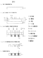
本発明の直接メタノール型燃料電池用電解質膜の製造方法の製造工程の一例をを図1(a)〜(e)に示す。
図1(a)に示す高分子薄膜配置工程おいて、まず、高分子薄膜1を準備する。エックス線が高分子薄膜1の膜面に対して直角に照射され、エックス線照射工程で微動しないように高分子薄膜1をステージ(図示せず)等に固定する。
高分子薄膜材料には、薄膜状態においても機械的強度に優れていること、メタノール、水等に対して、膨潤、吸収等が発生せず、化学的に安定であること、また電解質膜の製造工程中の加熱や、高温での使用等を考慮し、耐熱性に優れた特性が要求される。本発明に用いる高分子薄膜材料としては、上記特性に優れたフッ素樹脂あるいはケイ素樹脂を用いる。両材料とも、機械的強度に優れた薄膜が作製可能であり、撥水性に優れメタノールにも比較的安定な化合物である。
【0012】
本発明に用いるフッ素樹脂には、デュポン社製テフロン(登録商標)フィルムに代表される4フッ化エチレン−6フッ化プロピレン共重合体、4フッ化エチレン−パーフロロアルコキシ共重合体が専ら用いられるが、ポリテトラフルオロエチレン、ポリテトラフルオロエチレン架橋体、ポリエチレンを構成する水素の一部をフッ素置換したポリフッ化ビニリデン、ポリ3フッ化エチレン等のフッ素化ポリエチレン等、フッ素基の導入により撥水性を有し、メタノールに対して化学的に安定であり、製膜性に優れているものであればよい。また、本発明にケイ素樹脂には専らポリシロキサンを用いることができ、ポリシロキサン中の有機基が、メチル基であるポリジメチルシロキサンが好適に用いられるが、フェニル基、水素基、水酸基等であってもよい。
【0013】
ポリシロキサン薄膜は、低粘性の液状シロキサンオリゴマーを、所定の割合で硬化剤と混合し型枠等に流し込むことにより、溶剤で溶解することなく得ることができる。硬化に要する時問は、室温で約2時間、温度を上げることによりさらに短くできる。フッ素樹脂、ケイ素樹脂ともにフィルムの厚さは、0.5〜100μm、好ましくは1〜50μmであり、0.5μm以下であると機械的強度が低下し、後述する電解質層充填工程で膜が破れ易くなり、また空気中の酸素が空気極から燃料極へ透過し電池性能を低下させる。また、100μmより厚くなると該フィルムを貫通する空孔作製が困難となると共に、微細孔中に充填する電解質層の厚さも必然的に厚くなることから、イオン伝導性が低下し、電池の性能を低下させる。
【0014】
次に、高分子薄膜1上部へのマスク3の配置工程を図1(b)に示す。本発明に用いるマスク3は、所望の部分が取り除かれたシリコンウェハ3a上に、エックス線透過率が高い無機化合物膜3bが配置され、さらにその上に、微細な複数の円形または多角形状の空孔パターン3dを有するエックス線吸収体層3cが形成された構造である。前記エックス線透過率の高い無機化合物の膜3bは、膜厚が0.1〜10μmのシリコンカーバイトが好適に用いられるが、窒化シリコン、ダイヤモンド、あるいはこれらの複合膜等、エックス線透過率の高い膜であればよい。エックス線吸収体層3cには、膜厚が0.1〜2μmのタンタルが好適に用いられるが、微細なパターンを作製できるものであればよい。前記エックス線吸収体層3cに形成される空孔パターン3dは、電子ビーム描画装置でレジストパターンを形成した後、エックス線吸収体層をエッチングすることにより得られる。空孔パターン3dは、内径0.01〜5μmの円形または多角形状であることが望ましい。空孔パターン0.01μm未満では、空孔の作製が困難となり、5μmを超えると電解質膜の耐クロスオーバー特性が低下してしまう。空孔パターンの形状は、4角形以上の多角形であることが望ましい。これは、空孔パターンに鋭角な部分があると電解質充填が困難となるためである。また、空孔パターンにおける空孔と空孔との問隔は、小さい方が電解質膜に占める電解質部の割合が多くなり、好ましいが、小さすぎると空孔パターンの作製が困難となること、またエックス線照射時、熱分解等によりに隣り合う空孔同士が連結されてしまうことから、0.01μm以上を必要とする。前記の性能を有するマスク3を高分子薄膜上に位置合わせして配置する。位置合わせに際しては、高分子薄膜1とシリコンウエハ3aとの問に適宜スペーサ等を配置してもよい。
【0015】
次に、高分子薄膜1にエックス線照射により複数の均一な微細空孔を設ける、エックス線照射−微細空孔作製工程を、図1(c)に示す。高分子薄膜1への均一な微細空孔1a〔図1(d)参照〕は、高分子薄膜1にマスク3を介してエックス線2を照射することにより得られる。使用するエックス線2は、約1keVにピークを持った0.4〜5keV領域のエヅクス線2を選択する。該マスク3を透過したエックス線2のみが高分子薄膜1のエックス線照射部分2aに照射されエッチングされることにより、図1(d)「エックス線照射後の高分子薄膜の状態」に示されるように、微細空孔1aを有する高分子薄膜1を作製することが可能となる。エックス線照射時間は、できるだけ短い方が、高分子薄膜が熱による損傷を受けにくく、鋭利な空孔を作製できることから、0.1〜10ekV領域のエックス線で数分〜数十分以内であることが好ましい。照射時間の短縮や加工精度を向上させるため、照射時高分子薄膜1を加熱することが可能である。空孔率ば、20〜90%であり、50〜80%が好ましく、90%以上の空孔率では膜の強度が著しく低下し、20%以下ではイオン伝導性が低くなり、著しく電池性能を低下させる。このエックス線照射工程は、10−5Torr(≒1.33×10−3Pa)以下の高真空槽内で行うのが好ましい。
【0016】
次に、微細な空孔を複数設けたフッ素樹脂、ケイ素樹脂薄膜中に、電解質成分を充填する工程を図1(d)および図1(e)「電解質充填工程」を用いて説明する。この工程は、前記図1(c)エックス線照射−微細空孔作製工程の後、乾燥窒素などの不活性ガス雰囲気中等で直ちに行うことが好ましい。これは、前記図1(c)工程で作製した微細空孔1a内部のエッチング面がエックス線照射により分子結合性の高い活性点1bを有しており、空孔内部の面と電解質成分4との結合性が増すためである。
【0017】
この図1(e)「電解質充填工程」に用いられる第一の電解質成分充填方法としては、電解質成分4の原料であるイオン伝導基を有するモノマーおよび若干量の重合開始剤を、微細空孔1aを複数設けた高分子薄膜1の上部より滴下して空孔内を充填し、硬化させることにより薄膜中にイオン伝導部を形成することが可能となる。硬化反応は、加熱、紫外線照射などによって促進し、また適宜架橋剤を用いることにより架橋結合を導入しても良い。イオン伝導基を有するモノマーには、構造中にスルホン酸等の強酸基を有する化合物、例えばビニルスルホン酸、ビニルホスホン酸、アリルスルホン酸、アリルホスホン酸、スチレンスルホン酸、スチレンホスホン酸が好ましいが、本発明ではこれらに限定されるものではない。また、この「電解質充填工程」は、高分子薄膜1の一方の面を吸引もしくば減圧しながら、もう一方の面から、微細空孔1a内へ電解質成分4を充填することが、電解質成分が上記微細空孔1a内へ浸入しやすくなり、好ましい。
【0018】
あるいは、この図1(e)「電解質充填工程」に用いられる第二の電解質成分充填方法としては、イオン伝導性高分子の溶液あるいは反応性オリゴマー等の高分子前駆体を溶解した溶液を調整し、その中に微細な空孔を複数設けたフッ素樹脂またはケイ素樹脂薄膜を浸漬した後、この膜を乾燥して、溶媒を除去する。高分子前駆体を用いた場合には、その後、加熱等による高分子化または架橋反応による高分子化を行い空孔内への充填を完了する。この高分子溶液または高分子前駆体溶液として、ポリサルホン、ポリベンズイミダゾールあるいはポリエーテルエーテルケトンなどのスルホン化ポリマー、パーフルオロアルキルスルホン酸の溶液を用いることができるが、本発明においては、これらに限定されるものではない。本発明では、上記第一および第二の電解質成分の充填方法を適宜組み合わせることによって、空孔壁面の疎水的性質が親水性へと変化してくるため、電解質成分の充填が一層容易となり、より緻密で均一な電解質層の形成が可能となる。
【0019】
あるいは、この図1(e)「電解質充填工程」に用いられる第三の電解質成分充填方法としては、イオン伝導性ガラスとなり得るゾルを作製し、その中に微細な空孔を複数設けたフッ素樹脂またはケイ素樹脂薄膜基板を浸漬あるいは前記ゾルを塗布した後、乾燥、加熱することにより得られる。本法では、テトラメトキシシラン、テトラメトキシリン酸をアルコールに溶解したゾルが好適に用いられるが、本発明ではこれらに限定されるものではない。
また、本発明においては、上記の高分子薄膜中の空孔内に電解質を充填する工程の前に、電解質が空孔内に速やかに浸入させると共に、電解質と高分子薄膜との結着性を向上させるため、シランカップリング剤等による空孔内の親水化処理、グリシジルメタクリレート等のエポキシ基をもつモノマーを空孔内へ放射線グラフ重合させた後、エポキシ基をスルホン基置換する等の親水化処理を行ってもよい。あるいは、アルゴンプラズマ処理して空孔表面を再活性化処理しても良い。
以上の方法で作製した電解質部の両面に、触媒層、ガス拡散層を兼ねた集電板を配置し、ホットプレス法等により接合して、燃料極および空気極を作成する。燃料極用の触媒層は、Pt−Ruを主成分としたメタノール酸化触媒が、空気極用触媒層には、Ptを主成分とした酸素還元触媒が専ら用いられ、Decal法やスプレー法等で作製することにより得られるが、本発明ではこれらの作製法に限定されるものではない。
【0020】
【実施例】
さらに、本発明の実施例を挙げ、詳細に説明するが、本発明はこれらの実施例に限定されるものではない。
〈実施例1〉
表面研磨した厚さ12.5μmのデュポン社製ポリテトラフルオロエチレン膜を有機溶剤で洗浄し、超高真空槽内に放射光に対面するよう配置した。シリコンウエハ上に厚さ2μmのエックス線透過率の高いシリコンカーバイト層、その上に孔径0.05μm、空孔率50%の空孔パターンを有する厚さ0.8μmのタンタル層を有するエックス線マスクを前記ポリテトラフルオロエチレン膜前面に平行になるよう配置した。真空槽内の真空度は、5×10⁻⁸Torr(≒6.65×10⁻⁶Pa)に達した後、エックス線照射を行った。放射光には、約1keVにピークを持った0.4〜5keV領域のエックス線を用い、照射時間は5分であった。照射後、薄膜を取り出しSEM観察したところ、前記薄膜には孔径0.05μm、空孔率50%の空孔パターンを有することを確認した。その空孔内に、窒素雰囲気中でビニルスルホン酸系高分子電解質を充填することにより電解質部を形成し、その電解質部の一方の面にカーボン担持されたPt−Ru触煤層、集電板をホットプレスし圧着することにより燃料極を形成し、もう一方の面にカーボン担持されたPt触媒層を形成しプラスチック基板を作製した。得られた電解質膜について、プロトンイオン伝導性をインピーダンス測定装置により測定した。 その結果、プロトン伝導率は、室温25℃において、0.15S/cmとNafion膜(0.08S/cm)に比べ高いプロトン伝導率を示すことが分かった。また、膜電極複合体のI−V特性を測定した結果、温度約40℃、大気圧中で、最大出力は50mW/cm2であり、Nafion膜を電解質膜に用いたときの最大出力20mW/cm2に比べ、高い出力が得られた。また、メタノールの透過性試験を行った結果、Nafion膜の1/10以下の透過量であった。
【0021】
〈実施例2〉
ポリジメチルシロキサンの高分子前駆体の主剤および硬化剤(Sylgard 184:Dow Corning Co.)を10:1の割合で混合し、充分に撹拌した後に15分間真空脱ガスしてプレポリマー混合液を作製した。このプレポリマー混合液をマスター上に注ぎ、65℃で1時間、95℃で15分間キュアリングを行った。こうして得られた厚さ50μmポリジメチルシロキサン膜中央部に、実施例1と同じ放射線加工を行い、SEM観察したところ前記薄膜には孔径0.04μm、空孔率45%の空孔パターンを有することを確認した。その空孔内にビニルスルホン酸系高分子電解質を充填することにより電解質部を形成し、その電解質部の一方の面にカーボン担持されたPt−Ru触媒層、集電板をホットプレスし圧着することにより燃料極を形成し、もう一方の面にカーボン担特されたPt触媒層を形成しプラスチヅク基板を作製した。
その結果、プロトン伝導率は、室温25℃において、0.10S/cmと高いプロトン伝導率を示すことが分かった。また、膜電極複合体のI−V特性を測定した結果、温度約40℃、大気圧中で、最大出力は45mW/cm2であり、高い出力が得られた。また、メタノールの透過性試験を行い、Nafion膜の1/10以下の透過量であった。
【0022】
【発明の効果】
本発明により、メタノールの透過(クロスオーバー)を抑制し、イオン伝導性に優れた新規な直接メタノール型燃料電池用電解質膜の製造方法を提供できる。
【図面の簡単な説明】
【図1】本発明の実施の形態で例示した直接メタノール型燃料電池用電解質膜の製造方法の各工程における高分子薄膜の状態を示す工程図。
【図2】従来技術による電解質膜の状態を示す模式図。
【符号の説明】
1…高分子薄膜
1a…微細空孔
1b…活性点
2…エックス線
2a…エックス線照射部分
3…マスク
3a…シリコンウエハ
3b…無機化合物膜
3c…エックス線吸収体層
3d…空孔パターン
4…電解質成分
5…延伸多孔質高分子薄膜
6…微細空孔
7…電解質成分[0001]
TECHNICAL FIELD OF THE INVENTION
The present invention relates to a method for producing an electrolyte membrane for a direct methanol fuel cell, which is excellent in methanol permeation resistance and capable of achieving high output, as a power source for a mobile device such as a mobile phone.
[0002]
[Prior art]
[Non-patent document 1]
"Satoru Hikida, Kimitaka Yamane, Yasuo Nakajima: Effects of Operating Conditions and MEA Properties on Methanol Crossover in Direct Methanol Fuel Cells, Preprints, No. 81-00, pp.1 -6, (2000) "
Direct methanol fuel cells are being researched and developed as small, portable power sources, taking advantage of their features from the viewpoints of fuel convenience, safety, and the need for a reformer. Until now, a perfluoro (alkyl) sulfonic acid membrane (trade name: Nafion) has been used exclusively as an electrolyte membrane for direct methanol power generation. However, during power generation, methanol as a fuel permeates the electrolyte membrane ( Crossover), which has the disadvantage of lowering battery performance. (Non-Patent Document 1)
This is because the affinity between methanol and the electrolyte membrane is very good, and the electrolyte membrane swells in an aqueous methanol solution, so that methanol can easily enter the electrolyte membrane. To overcome this drawback, there is a need to design a new electrolyte membrane that suppresses swelling in methanol aqueous solution and allows small-sized hydrogen ions to permeate but not large-sized methanol. For example, a method for manufacturing an electrolyte membrane that suppresses methanol permeation and allows only hydrogen ions to permeate by filling an electrolyte component in a stretched porous polymer membrane that is chemically stable to methanol has been studied. However, it did not lead to sufficient performance. FIG. 2 schematically shows the structure of a conventional electrolyte produced by such a method. In general, the stretched porous polymer thin film 5 is formed by stretching the polymer film and tearing each minute portion to form an infinite number of fine holes 6. The polymer film produced by such a method has a non-uniform pore itself and a distribution width with a certain pore size. Have swelled in the aqueous methanol solution, which has become a methanol conduction path, and has a problem that the amount of permeated methanol cannot be reduced.
[0003]
[Problems to be solved by the invention]
As described above, the conventional electrolyte membrane for a direct methanol fuel cell has a problem that it cannot simultaneously satisfy both the properties of hydrogen ion conductivity and methanol permeation resistance. In order to satisfy these characteristics, there has been a demand for a method of producing fine pores having a uniform pore diameter and filling the fine pores with an electrolyte component.
[0004]
An object of the present invention is to solve the above-mentioned problems in the conventional technology, and to provide a method for producing an electrolyte membrane for a direct methanol fuel cell having excellent resistance to methanol permeation as a power supply for a mobile phone or the like. is there.
[0005]
[Means for Solving the Problems]
In order to achieve the above object, the present invention is configured as described in the claims. That is,
2. A direct methanol fuel cell according to claim 1, wherein the fuel is methanol, and the supply of the methanol is supplied to generate power by an electrochemical reaction. The fuel cell includes an electrolyte membrane having cation conductivity, the electrolyte membrane comprising: In a method for producing an electrolyte membrane for a direct methanol fuel cell, wherein a fuel electrode is provided on one side of the
Providing a mask having a plurality of fine circular or polygonal X-ray transmission patterns on top of the polymer thin film,
Forming a plurality of fine holes in the polymer thin film by irradiating X-rays from above the mask;
And a step of filling the fine pores with an electrolyte component, which is a method for producing an electrolyte membrane for a direct methanol fuel cell.
[0006]
Further, as set forth in claim 2, in claim 1, the mask is such that a film of an inorganic compound having a high X-ray transmittance is disposed on a silicon wafer from which a desired portion has been removed, and further a fine pattern is further formed thereon. The present invention provides a method for producing an electrolyte membrane for a direct methanol fuel cell having a laminated structure in which a plurality of X-ray absorber layers having a plurality of circular or polygonal void patterns are formed.
[0007]
According to a third aspect of the present invention, in the second aspect, the inorganic compound film having a high X-ray transmittance is silicon carbide, the film thickness is in a range of 0.1 to 10 μm, and the X-ray absorption The electrolyte membrane for a direct methanol fuel cell, wherein the body layer is tantalum having a thickness of 0.1 to 2 μm and the pore pattern formed in the X-ray absorber layer is a circular or polygonal shape having an inner diameter of 0.01 to 5 μm. It is a manufacturing method.
[0008]
According to a fourth aspect of the present invention, there is provided the method for producing an electrolyte membrane for a direct methanol fuel cell according to the first aspect, wherein the polymer thin film is formed of a fluororesin or a silicon resin having a thickness of 0.5 to 100 μm. Things.
[0009]
Further, as described in claim 5, in claim 1, a monomer solution, a polymer solution, a polymer precursor solution, or an inorganic electrolyte sol that forms an ion-conductive solid polymer is used as the electrolyte component. The method for producing a direct methanol fuel cell electrolyte membrane, wherein, after the vacancy producing treatment by the X-ray irradiation, the fine pores in the polymer thin film are filled in an inert gas atmosphere, and then polymerized or dried. Is what you do.
[0010]
According to a sixth aspect of the present invention, in the fifth aspect, a monomer solution for forming an ion-conductive solid polymer from the other surface while suctioning or depressurizing one surface of the polymer thin film is used. The present invention provides a method for producing an electrolyte membrane for a direct methanol fuel cell, in which a molecular solution, a polymer precursor solution or an inorganic electrolyte sol is applied or dropped, and pores are filled with an electrolyte component.
[0011]
BEST MODE FOR CARRYING OUT THE INVENTION
<Embodiment 1>
FIGS. 1A to 1E show an example of the manufacturing process of the method for manufacturing an electrolyte membrane for a direct methanol fuel cell according to the present invention.
In the polymer thin film disposing step shown in FIG. 1A, first, a polymer thin film 1 is prepared. An X-ray is irradiated at right angles to the film surface of the polymer thin film 1, and the polymer thin film 1 is fixed to a stage (not shown) or the like so as not to move slightly in the X-ray irradiation step.
The polymer thin film material has excellent mechanical strength even in a thin film state, does not swell or absorb in methanol, water, etc., and is chemically stable. Considering heating during the process, use at high temperature, etc., characteristics with excellent heat resistance are required. As the polymer thin film material used in the present invention, a fluororesin or a silicon resin excellent in the above properties is used. Both materials can produce a thin film having excellent mechanical strength, are excellent in water repellency, and are relatively stable to methanol.
[0012]
As the fluororesin used in the present invention, a tetrafluoroethylene-6-fluoropropylene copolymer represented by a Teflon (registered trademark) film manufactured by DuPont is exclusively used. However, polytetrafluoroethylene, polytetrafluoroethylene crosslinked product, polyvinylidene fluoride in which a part of hydrogen constituting polyethylene is substituted by fluorine, fluorinated polyethylene such as polytrifluoride ethylene, etc., have water repellency by introducing fluorine groups. What is necessary is just to have a chemical stability with respect to methanol, and to be excellent in film-forming property. In the present invention, polysiloxane can be exclusively used for the silicon resin, and polydimethylsiloxane in which the organic group in the polysiloxane is a methyl group is preferably used. However, a phenyl group, a hydrogen group, a hydroxyl group, or the like can be used. You may.
[0013]
The polysiloxane thin film can be obtained without mixing with a solvent by dissolving a low-viscosity liquid siloxane oligomer at a predetermined ratio with a curing agent and pouring the mixture into a mold or the like. The time required for curing can be further reduced by raising the temperature for about 2 hours at room temperature. The film thickness of both the fluororesin and the silicon resin is 0.5 to 100 μm, preferably 1 to 50 μm, and if it is 0.5 μm or less, the mechanical strength is reduced, and the film is broken in the electrolyte layer filling step described later. In addition, oxygen in the air permeates from the air electrode to the fuel electrode, which lowers the cell performance. On the other hand, if the thickness is more than 100 μm, it becomes difficult to form pores penetrating the film, and the thickness of the electrolyte layer to be filled in the micropores is inevitably increased. Lower.
[0014]
Next, a process of disposing the mask 3 on the polymer thin film 1 is shown in FIG. In the mask 3 used in the present invention, an inorganic compound film 3b having a high X-ray transmittance is arranged on a silicon wafer 3a from which a desired portion has been removed, and a plurality of fine circular or polygonal holes are further formed thereon. This is a structure in which an X-ray absorber layer 3c having a pattern 3d is formed. As the film 3b of the inorganic compound having a high X-ray transmittance, silicon carbide having a thickness of 0.1 to 10 μm is preferably used, but a film having a high X-ray transmittance such as silicon nitride, diamond, or a composite film thereof is used. Should be fine. Tantalum having a thickness of 0.1 to 2 μm is preferably used for the X-ray absorber layer 3c, but any material that can produce a fine pattern may be used. The hole pattern 3d formed in the X-ray absorber layer 3c is obtained by forming a resist pattern with an electron beam lithography apparatus and then etching the X-ray absorber layer. The hole pattern 3d is desirably a circular or polygonal shape having an inner diameter of 0.01 to 5 μm. If the hole pattern is less than 0.01 μm, it is difficult to form holes, and if it exceeds 5 μm, the crossover resistance of the electrolyte membrane will be reduced. The shape of the hole pattern is desirably a polygon of a quadrangle or more. This is because it is difficult to fill the electrolyte if the hole pattern has an acute angle portion. In addition, the gap between the pores and the pores in the pore pattern, the smaller the proportion of the electrolyte portion occupying the electrolyte membrane is preferable, it is preferable, if too small, it is difficult to produce a pore pattern, At the time of X-ray irradiation, adjacent holes are connected to each other due to thermal decomposition or the like. The mask 3 having the performance described above is positioned and arranged on the polymer thin film. At the time of positioning, a spacer or the like may be appropriately arranged between the polymer thin film 1 and the silicon wafer 3a.
[0015]
Next, an X-ray irradiation-fine hole forming step of providing a plurality of uniform fine holes in the polymer thin film 1 by X-ray irradiation is shown in FIG. Uniform fine holes 1a (see FIG. 1D) in the polymer thin film 1 are obtained by irradiating the polymer thin film 1 with X-rays 2 through a mask 3. As the X-ray 2 to be used, an X-ray 2 in a 0.4 to 5 keV region having a peak at about 1 keV is selected. Only the X-rays 2 transmitted through the mask 3 are irradiated to the X-ray irradiated portion 2a of the polymer thin film 1 and etched, as shown in FIG. 1 (d) "State of polymer thin film after X-ray irradiation". The polymer thin film 1 having the fine holes 1a can be manufactured. The shorter the X-ray irradiation time, the shorter the X-ray irradiation time in the range of 0.1 to 10 ekV X-ray, because the polymer thin film is less likely to be damaged by heat and can form sharp holes. preferable. In order to shorten the irradiation time and improve the processing accuracy, it is possible to heat the polymer thin film 1 during irradiation. The porosity is 20 to 90%, preferably 50 to 80%. At a porosity of 90% or more, the strength of the membrane is significantly reduced, and at a porosity of 20% or less, the ionic conductivity is lowered, and the battery performance is significantly reduced. Lower. This X-ray irradiation step is preferably performed in a high vacuum chamber of 10 −5 Torr (≒ 1.33 × 10 −3 Pa) or less.
[0016]
Next, a step of filling an electrolyte component into a fluororesin or silicon resin thin film having a plurality of fine pores will be described with reference to FIGS. 1D and 1E "Electrolyte filling step". This step is preferably performed immediately in an atmosphere of an inert gas such as dry nitrogen or the like after the step of irradiating X-rays and forming fine pores shown in FIG. This is because the etched surface inside the fine holes 1a produced in the step of FIG. 1 (c) has active points 1b having high molecular bonding property by X-ray irradiation, and the surface between the inside of the holes and the electrolyte component 4 This is because the binding property increases.
[0017]
As a first method for filling the electrolyte component used in the "electrolyte filling step" in FIG. 1 (e), a monomer having an ion conductive group, which is a raw material of the electrolyte component 4, and a small amount of a polymerization initiator are mixed with the fine pores 1a. Is dropped from the upper part of the polymer thin film 1 provided with a plurality of particles, and the pores are filled and cured to form an ion conductive portion in the thin film. The curing reaction is accelerated by heating, irradiation with ultraviolet light, or the like, and a crosslinking bond may be introduced by using a crosslinking agent as appropriate. The monomer having an ion conductive group, a compound having a strong acid group such as sulfonic acid in the structure, for example, vinyl sulfonic acid, vinyl phosphonic acid, allyl sulfonic acid, allyl phosphonic acid, styrene sulfonic acid, styrene phosphonic acid is preferred, The present invention is not limited to these. In this “electrolyte filling step”, filling or filling the micropores 1 a with the electrolyte component 4 from the other surface while suctioning or depressurizing one surface of the polymer thin film 1 is performed. This is preferable because it easily penetrates into the minute holes 1a.
[0018]
Alternatively, as a second electrolyte component filling method used in the “electrolyte filling step” in FIG. 1E, a solution of an ion conductive polymer or a solution in which a polymer precursor such as a reactive oligomer is dissolved is prepared. After immersing a fluororesin or silicon resin thin film having a plurality of fine holes therein, the film is dried to remove the solvent. In the case where the polymer precursor is used, thereafter, the polymerization by heating or the like or the polymerization by a cross-linking reaction is performed to complete the filling of the pores. As the polymer solution or polymer precursor solution, a sulfonated polymer such as polysulfone, polybenzimidazole or polyetheretherketone, or a solution of perfluoroalkylsulfonic acid can be used, but in the present invention, the solution is not limited to these. It is not done. In the present invention, by appropriately combining the method of filling the first and second electrolyte components, the hydrophobic property of the pore wall surface changes to hydrophilic, so that the filling of the electrolyte component is further facilitated, A dense and uniform electrolyte layer can be formed.
[0019]
Alternatively, as a third electrolyte component filling method used in the “electrolyte filling step” in FIG. 1E, a fluorinated resin in which a sol that can be ion-conductive glass is produced and a plurality of fine pores are provided therein is provided. Alternatively, it can be obtained by immersing a silicon resin thin film substrate or applying the sol, followed by drying and heating. In the present method, a sol obtained by dissolving tetramethoxysilane and tetramethoxyphosphoric acid in an alcohol is preferably used, but the present invention is not limited to these.
Further, in the present invention, before the step of filling the pores in the polymer thin film with the electrolyte, the electrolyte is quickly penetrated into the pores, and the binding property between the electrolyte and the polymer thin film is improved. To improve the hydrophilicity of the pores with a silane coupling agent, etc., and after radiation-polymerizing a monomer having an epoxy group such as glycidyl methacrylate into the pores, replace the epoxy group with a sulfone group. Processing may be performed. Alternatively, the pore surface may be reactivated by argon plasma treatment.
A current collector plate serving also as a catalyst layer and a gas diffusion layer is arranged on both sides of the electrolyte part produced by the above method, and joined by a hot press method or the like to form a fuel electrode and an air electrode. For the catalyst layer for the fuel electrode, a methanol oxidation catalyst mainly containing Pt-Ru is used, and for the catalyst layer for the air electrode, an oxygen reduction catalyst mainly containing Pt is mainly used. Although it can be obtained by manufacturing, the present invention is not limited to these manufacturing methods.
[0020]
【Example】
Furthermore, the present invention will be described in detail with reference to examples, but the present invention is not limited to these examples.
<Example 1>
A 12.5 μm-thick polytetrafluoroethylene film manufactured by DuPont with a polished surface was washed with an organic solvent and placed in an ultrahigh vacuum chamber so as to face the emitted light. An X-ray mask having a 2 μm-thick silicon carbide layer having a high X-ray transmittance on a silicon wafer and a 0.8 μm-thick tantalum layer having a hole pattern having a hole diameter of 0.05 μm and a porosity of 50% is formed thereon. It was arranged so as to be parallel to the front surface of the polytetrafluoroethylene film. After the degree of vacuum in the vacuum chamber reached 5 × 10 −8 Torr (≒ 6.65 × 10 −6 Pa), X-ray irradiation was performed. X-rays in the range of 0.4 to 5 keV having a peak at about 1 keV were used for the emitted light, and the irradiation time was 5 minutes. After the irradiation, the thin film was taken out and observed by SEM. As a result, it was confirmed that the thin film had a pore pattern with a pore diameter of 0.05 μm and a porosity of 50%. The pores are filled with a vinyl sulfonic acid-based polymer electrolyte in a nitrogen atmosphere to form an electrolyte part, and a carbon-supported Pt-Ru catalyst layer and a current collector plate are formed on one surface of the electrolyte part. A fuel electrode was formed by hot pressing and pressure bonding, and a Pt catalyst layer carrying carbon was formed on the other surface to produce a plastic substrate. Proton ion conductivity of the obtained electrolyte membrane was measured by an impedance measuring device. As a result, the proton conductivity was found to be 0.15 S / cm at room temperature and 25 ° C., which is higher than that of the Nafion film (0.08 S / cm). In addition, as a result of measuring the IV characteristics of the membrane electrode assembly, the maximum output was 50 mW / cm 2 at a temperature of about 40 ° C. and the atmospheric pressure, and the maximum output was 20 mW / cm 2 when the Nafion membrane was used as the electrolyte membrane. Higher output was obtained compared to cm 2 . As a result of a methanol permeability test, the permeation amount was 1/10 or less of the Nafion membrane.
[0021]
<Example 2>
A main component of a polymer precursor of polydimethylsiloxane and a curing agent (Sylgard 184: Dow Corning Co.) are mixed at a ratio of 10: 1, sufficiently stirred, and then vacuum degassed for 15 minutes to prepare a prepolymer mixed solution. did. The prepolymer mixture was poured onto a master and subjected to curing at 65 ° C. for 1 hour and at 95 ° C. for 15 minutes. The center of the thus obtained 50 μm-thick polydimethylsiloxane film was subjected to the same radiation processing as in Example 1 and observed by SEM. The thin film had a pore pattern of 0.04 μm in pore diameter and a porosity of 45%. It was confirmed. The pores are filled with a vinyl sulfonic acid-based polymer electrolyte to form an electrolyte part, and a carbon-supported Pt-Ru catalyst layer and a current collector plate on one surface of the electrolyte part are hot pressed and pressed. As a result, a fuel electrode was formed, and a Pt catalyst layer provided with carbon was formed on the other surface to produce a plastic substrate.
As a result, the proton conductivity was found to show a high proton conductivity of 0.10 S / cm at room temperature of 25 ° C. Further, as a result of measuring the IV characteristics of the membrane electrode assembly, the maximum output was 45 mW / cm 2 at a temperature of about 40 ° C. and atmospheric pressure, and a high output was obtained. Further, a methanol permeability test was performed, and the permeation amount was 1/10 or less of the Nafion membrane.
[0022]
【The invention's effect】
According to the present invention, it is possible to provide a novel method for producing an electrolyte membrane for a direct methanol fuel cell, which suppresses the permeation (crossover) of methanol and has excellent ion conductivity.
[Brief description of the drawings]
FIG. 1 is a process chart showing a state of a polymer thin film in each step of a method for manufacturing an electrolyte membrane for a direct methanol fuel cell exemplified in an embodiment of the present invention.
FIG. 2 is a schematic diagram showing a state of an electrolyte membrane according to a conventional technique.
[Explanation of symbols]
DESCRIPTION OF SYMBOLS 1 ... Polymer thin film 1a ... Micro vacancy 1b ... Active point 2 ... X-ray 2a ... X-ray irradiation part 3 ... Mask 3a ... Silicon wafer 3b ... Inorganic compound film 3c ... X-ray absorber layer 3d ... Void pattern 4 ... Electrolyte component 5 ... stretched porous polymer thin film 6 ... fine pores 7 ... electrolyte component