【0001】
【発明の属する技術分野】
本発明は、目標位置への走行軌跡を求めて、この走行軌跡に車両が追従するよう車両走行の支援を行う車両用走行支援装置に関し、特に、自動操舵により車両を誘導する車両用走行支援装置に関する。
【0002】
【従来の技術】
自動操舵や操舵指示を用いて、車両を目標位置へと誘導する技術が知られている(例えば、特許文献1参照)。例えば、車両の積載重量が変化すると、サスペンションのジオメトリーが変化するため、ステアリングホイールの転舵角に対する車輪の切れ角が変化してしまう。このようなサスペンションのジオメトリー変化が起こっても常に車両の移動軌跡を一致させるため、特許文献1の技術では、左右前輪それぞれの移動距離の関係が所定の関係にあるか否かを調べ、所定の関係を満たさない場合には、そのずれに応じて移動軌跡を修正することで、車両を目標位置へ正しく導くことができると記載されている。
【0003】
【特許文献1】
特開2001−63599号公報(段落0021〜0032、図4、図9)
【0004】
【発明が解決しようとする課題】
ところで、自動操舵装置を用いて経路誘導を行う場合、経路判定に走行距離と曲率が用いられるが、通常は、これらを判定するため、転舵角と車輪回転数が用いられている。しかしながら、車両の積載重量変化などにより転舵負荷が変化すると、同じ転舵を行うにも自動操舵の駆動装置(電動モータ等)の出力を大きくする必要があるため、駆動装置の出力が同じであれば、操舵に遅れが生じてしまう。この操舵遅れにより、現在の車両位置自体の推定精度が低下してしまう。また、経路を再設定しても、再設定経路からこの操舵遅れによりずれが生じてしまう場合がある。
【0005】
そこで本発明は、操舵遅れに起因する経路誘導の精度低下を抑制することが可能な自動操舵装置を用いた車両用走行支援装置を提供することを課題とする。
【0006】
【課題を解決するための手段】
上記課題を解決するため、本発明に係る車両用走行支援装置は、目標位置までの目標経路を設定し、自動操舵装置により操舵を行うことで、該目標経路に沿って車両を誘導する車両用走行支援装置において、操舵制御の目標値に対する遅れを判定する制御遅れ判定手段を備えており、判定した制御遅れを考慮して目標経路の最大曲率勾配を決定し、曲率勾配が決定した最大曲率勾配の範囲内となる目標経路を設定して誘導を行うことを特徴とする。
【0007】
操舵遅れは、操舵速度(時間当たりのステアリングホイールやステアリングシャフトの回転速度)が大きいほど大きくなる。そこで、操舵速度を制限することにより実際に発生する操舵遅れを抑制することができる。本発明では、操舵遅れの状態に応じて、旋回曲率の走行距離に対する変化量である曲率勾配の使用範囲を変更することにより、操舵速度が所定以上に達しない経路を選定し、操舵遅れの発生を抑制する。
【0008】
誘導中に目標経路を再設定する際には、誘導中に測定した制御遅れを用いて経路の再設定を行うことが好ましい。これにより、最初の目標経路から操舵遅れにより逸脱した場合でも、操舵遅れを考慮して再設定経路を選択するので、再設定後の目標経路からのずれを抑制することができ、確実に目標位置へ到達することができる。
【0009】
目標経路の再設定は、判定した操舵遅れ量が所定値以上に達した時点に行えばよい。このような場合には、経路からの逸脱が大きくなる一方、遅れを考慮することで目標経路へ至る経路を精度良く再設定することができる。
【0010】
制御遅れ判定手段は、目標操舵角と実舵角の偏差、目標操舵速度と実操舵速度の偏差、目標経路と実際の車両位置の偏差等に基づいて制御遅れを判定すればよい。これらから制御の遅れを精度良く判定することができる。
【0011】
ここで、車両位置の判定に際しては、制御遅れを考慮して操舵角に対する旋回曲率変化を推定し、推定した旋回曲率変化を用いて実際の車両位置を推定することが好ましい。これにより、車両位置の推定精度が向上する。
【0012】
この制御遅れ判定手段は、操舵負荷から制御遅れを判定してもよく、操舵負荷は、路面状態、転舵輪荷重、タイヤ空気圧、自動操舵装置の負荷のうち、少なくともいずれか1つを用いて推定することが好ましい。これらから制御の遅れを精度良く判定することができる。
【0013】
本発明に係る車両用走行支援装置は、目標位置までの目標経路を設定し、自動操舵装置により操舵を行うことで、該目標経路に沿って車両を誘導する車両用走行支援装置において、制御遅れを考慮して操舵角に対する旋回曲率変化を推定し、推定した旋回曲率変化を基にして自車両の現在位置の推定を行うことを特徴とするものでもよい。
【0014】
これにより、自車の現在位置を精度良く推定することができるので、経路設定や誘導を確実に行うことができる。
【0015】
この制御遅れは、操舵量に対する時間遅れまたは操舵量の走行距離に対する遅れとして推定すると取扱いが容易で好ましい。この制御遅れは、路面状態や転舵輪荷重に基づいて判定を行うとよい。
【0016】
【発明の実施の形態】
以下、添付図面を参照して本発明の好適な実施の形態について詳細に説明する。説明の理解を容易にするため、各図面において同一の構成要素に対しては可能な限り同一の参照番号を附し、重複する説明は省略する。
【0017】
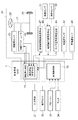
以下、本発明に係る走行支援装置として駐車支援装置を例に説明する。図1は、本発明の実施形態である駐車支援装置100のブロック構成図である。この駐車支援装置100は、自動操舵装置20を備えており、制御装置である駐車支援ECU1により制御される。駐車支援ECU1は、CPU、ROM、RAM、入力信号回路、出力信号回路、電源回路などにより構成されており、後述する後方カメラ32で取得された画像を処理する画像処理部10と、自動操舵装置の制御を行う操舵制御部11とを有している。この操舵制御部11には、操舵遅れ判定手段110が設けられている。この画像処理部10、操舵制御部11とは駐車支援ECU1内でハード的に区分されていてもよいが、共通のCPU、ROM、RAM等を用い、ソフト的に区分されていてもよい。操舵制御部11の操舵遅れ判定手段110も、駐車支援ECU1内で操舵制御部11の他の部分とハード的に区分されていてもよいが、共通のCPU、ROM、RAM等を用い、ソフト的に区分されていてもよい。
【0018】
ステアリングホイール22の動きを転舵輪25に伝えるステアリングシャフト21には、ステアリングシャフト21の操舵量を検出する操舵角センサ23と、操舵力を付与する操舵アクチュエータ24が接続されている。ここで、操舵アクチュエータ24は、自動操舵時に操舵力を付与するほか、運転者の操舵時にアシスト操舵力を付与するパワーステアリング装置を兼ねてもよい。この操舵アクチュエータ24は、電動モータを有しており、操舵制御部11は、操舵アクチュエータ24の駆動を制御する。そして、操舵遅れ判定手段110は、この操舵アクチュエータ24の作動電流を監視するとともに、操舵角センサ23の出力信号が入力されている。この出力信号は、操舵制御部11にも送られる。
【0019】
また、操舵制御部11には、操舵角センサ23の出力のほか、各輪に配置されてその車輪速を検出する車輪速センサ41と、車両の加速度を検出する加速度センサ42の出力が入力されている。一方、操舵遅れ判定手段110には、タイヤ空気圧測定装置44の出力が入力されている。このタイヤ空気圧測定装置44としては、各輪のホイール部にタイヤ内部の空気圧を直接検出するセンサを設け、その出力を無線により送信して車体に配置した受信部で受信して出力する直接測定方式や車輪速センサ41の出力を基にしてタイヤの共振周波数の変化をバネ定数の変化に換算し、空気圧の変化として検出する間接測定方式が利用できる。
【0020】
さらに、操舵遅れ判定手段110には、転舵輪荷重判定手段46の出力が入力される。この転舵輪荷重判定手段46には車両の前部(転舵輪側)の車高変化を検出する車高センサ51と、運転席、助手席の着席状況を検出する着座センサ52の出力が入力されている。また、操舵遅れ判定手段110には、路面摩擦係数推定手段47の出力も入力されている。この路面摩擦係数推定手段47は、車輪速センサ41の出力を基にして、駆動輪の回転状態から検出する方法等を利用することができる。
【0021】
駐車支援ECU1の前述した画像処理部10には、車両後部に配置されて、後方画像を取得する後方カメラ32の出力信号である画像信号が入力されるほか、駐車支援にあたって運転者の操作入力を受け付ける入力手段31と、運転者に対して画像により情報を表示するモニタ34と、音声により情報を提示するスピーカー33が接続されている。
【0022】
次に、この駐車支援装置における支援動作を具体的に説明する。以下では、図2に示されるように、道路210に面して設けられた車庫220内に、後退によって車両200を収容する、いわゆる車庫入れを行う場合の支援動作を説明する。図3は、この支援動作の第1の制御形態の制御処理を示すフローチャートであり、図4は、この制御における設定走行軌跡を説明する図である。
【0023】
図3に示される制御は、運転者が入力手段31を操作して、駐車支援制御の開始を駐車支援ECU1に指示してから、指示した目標駐車位置近傍へ到達するまで、あるいは、目標駐車位置へ1回の後退で到達することができないと判定されるまで、運転者が入力手段31から支援動作をキャンセルしない限り駐車支援ECU1により実行され続ける。
【0024】
具体的には、運転者は、車両200の基準点(以下の説明では、車両の後輪の車軸中心を基準点として説明する。もちろん、他の位置、例えば、車両の後端の中心や重心、片側の前端あるいは後端等を基準点にとってもよい。)が図2のA点に一致するよう車両200を移動させた後(この位置での車両を200aで表す。)、入力手段31により駐車支援動作の開始を指示する。そして、運転者はモニタ34に表示されている後方カメラ32で撮像した画像を見ながら、入力手段31を操作することにより、画面上に表示されている駐車枠を動かして目標駐車位置へと移動させることにより目標駐車位置の設定を行う(ステップS2)。
【0025】
駐車支援ECU1は、画像認識処理により目標駐車位置における車両位置200g、具体的には、基準点Gの位置と、その位置における車両の方向を求める(ステップS4)。このG点の位置は、例えば現在の車両位置における基準点Aに対する相対座標として求めればよい。以下、図2に示されるように、目標位置G点を原点とし、目標位置における車両の向きをz軸方向にとり、これに直交する方向をx軸にとった座標系により説明する。また、現在の車両の向きとz軸のなす角度を偏向角θ(初期位置における偏向角をθ0とする。)と称する。
【0026】
次に、現在の車両状態量から支援制御中に発生する操舵遅れを推定する(ステップS6)。本実施形態では、後述するように走行距離に旋回曲率を対応づけて経路を設定している。そして、所望の旋回曲率を得るために、操舵アクチュエータ24により舵角を変更する制御を行っている。ここでいう操舵遅れとは、操舵アクチュエータ24によってステアリングシャフト21を駆動してから、転舵輪25が転舵して所定の旋回曲率に達するまで(この所定の旋回曲率は、設定曲率である前述の所望の旋回曲率と異なる場合がある。)の遅れであり、例えば、時間遅れとして表すことができる。
【0027】
この操舵遅れの判定は、操舵遅れ判定手段110によって行われ、以下の車両状態量を基に操舵負荷の大小を推定し、推定した操舵負荷により操舵遅れを判定する。もちろん、車両状態量と操舵遅れの対応関係を把握しておいて、所定の車両状態量から操舵遅れを直接求めることもできる。
【0028】
第1の方法は、道路210を車庫220前からA点まで移動した際の道路210の路面摩擦係数μを路面摩擦係数推定手段47で推定し、このμが大きい場合には、支援中の操舵負荷が大きくなり、操舵遅れが大きくなるものと判定する。
【0029】
第2の方法は、転舵輪荷重に基づくものである。この転舵輪荷重は、転舵輪荷重判定手段46により判定されるものであり、車高センサ51で測定した前輪、つまり、転舵輪25側の車高が低下した場合や、着座センサ52の測定結果から、前席(運転席および助手席)側に乗車している場合に転舵輪25側に荷重がかかっており、支援中の操舵負荷が大きくなり、操舵遅れが大きくなると判定する。ここでは、車高センサ51と着座センサ52の両方を用いる場合を説明したが、いずれか一方のみを用いても良く、着座センサ52を用いる場合、後部席側の着座状態は、転舵輪荷重への影響が小さく、また、運転者は必ず乗車していることから、助手席のみの着座状態を基にして推定を行うこともできる。
【0030】
第3の方法は、空気圧測定装置44で測定した転舵輪25のタイヤ空気圧に基づくものである。タイヤの空気圧が低いほど、操舵負荷が大きくなることから、操舵遅れが大きくなるものと推定する。
【0031】
第4の方法は、操舵アクチュエータ24を構成する電動モータのアシスト電流に基づくものである。これは、支援開始前、例えば、道路210を車庫220前からA点まで移動する際に、運転者の操舵に合わせて電動モータによりアシスト操舵力を付与した際のアシスト電流を測定し、このアシスト電流が大きい場合には、操舵負荷が大きいとして、支援制御中においても操舵遅れが大きくなるものと推定する。
【0032】
操舵遅れ量の推定にあたっては、この4つの方法のいずれか1つまたは複数を組み合わせて行うことができる。操舵負荷に影響する複数のパラメータに対応するよう複数の方法を組み合わせればより精度の高い操舵遅れの推定が可能となるが、1つの方法のみを用いる場合には、簡便な手法で操舵遅れを推定することができる利点がある。
【0033】
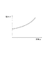
操舵遅れ量を推定したら、この操舵遅れ量に基づいて駐車支援制御において利用可能な最大曲率勾配を設定する(ステップS8)。この最大曲率勾配とは、走行距離に対する旋回曲率の変化量の最大値を指す。図5は、操舵遅れ量dに対するこの最大曲率勾配ωmaxの設定曲線の例を示すグラフである。操舵遅れ量dが大きいほど、最大曲率勾配ωmaxは小さくすることで、制御において実際に発生する操舵遅れを所定量以下に抑制することができる。この設定曲線は、図5中に実線で示すように、操舵遅れ量dが小さいときの操舵遅れ量dの増加量に対する最大曲率勾配ωmaxの減少量を操舵遅れ量dが大きいときの操舵遅れ量dの増加量に対する最大曲率勾配ωmaxの減少量より大きく設定してもよいし、破線で示すように操舵遅れ量dの増加量に対する最大曲率勾配ωmaxの減少量を一定として設定曲線を直線としてもよい。
【0034】
次に、設定された最大曲率勾配ωmaxの範囲内で現在位置A点から目標位置G点へと至る誘導経路P0を算出する(ステップS10)。以下、初期舵角が中立状態の場合を例に説明する。この誘導経路P0は、舵角中立状態のまま後退する過程(過程1)と、舵角を増大させる過程(過程2)と、増大した状態で舵角を保持する過程(過程3)と、舵角を中立に戻す過程(過程4)と、再び舵角中立状態のまま後退する過程(過程5)の5つの過程からなり、過程2と過程4においては、走行距離に対する旋回曲率の変化量(旋回曲率の変化速度)の絶対値を設定した最大曲率勾配ωmax以下に設定している(実際には、ωmaxに一致させている)。
【0035】
こうして設定される軌跡の代表例は、まず、A点からB点までは、操舵中立状態で後退し(過程1)、B点からC点までは旋回曲率の変化速度をωmaxで旋回曲率を増大させていき、C点で旋回曲率が設定最大値γmaxで、旋回半径が設定最小旋回半径(Rmin=1/γmax)となる状態に移行する(過程2)。C点からD点まではこの旋回曲率、旋回半径を維持する(過程3)。D点からは逆に旋回曲率の変化速度を−ωmaxとして、旋回曲率を減少させて、E点で舵角0の中立状態へと移行する(過程4)。そして、E点からG点までは、この中立状態で後退する(過程5)
この結果、走行軌跡P0は、AB間、EG間が直線、CD間が半径Rmin(曲率γmax)の円弧であり、BC間、DE間は、それぞれ一端が曲率γmax、他端が曲率0のクロソイド曲線となる。偏向角θが小さい場合や、AG間の距離が短い場合には、いずれか1つないし複数の過程を有しない場合もありうる。ここで偏向角θの変化量Δθは、Δθ=∫δdpで表せる。すなわち、偏向角の変化量Δθは、図4に示される走行軌跡の面積S0に合致する。
【0036】
次に、経路が設定できたか否かを判定する(ステップS12)。最大旋回曲率ωmaxを維持しても現在位置A点から目標位置G点に到達できず、経路設定不能と判定した場合には、ステップS50に移行し、現在位置Aからは目標位置G点に到達できない旨をモニタ34やスピーカー33を用いて運転者に報知し、処理を終了する。運転者は、必要であれば、車両200を移動させて再度駐車支援動作を作動させればよい。
【0037】
目標経路が設定できた場合には、ステップS14に移行して、実際の支援制御へと移行する。ここで、駐車支援ECU1は、シフトレバーが後退位置に設定されたら、図示していない駆動系に対して、エンジンのトルクアップ制御を行うよう指示することが好ましい。トルクアップ制御とは、エンジンを通常のアイドル時より高い回転数で回転させることで、駆動力の高い状態(トルクアップ状態)に移行させるものである。。これにより、運転者がアクセル操作を行うことなく、ブレーキペダルのみで調整できる車速範囲が拡大し、車両のコントロール性が向上する。運転者がブレーキペダルを操作すると、そのペダル開度に応じて各輪に付与される制動力を調整することで車速の調整を行う。このとき、車輪速センサ32で検出している車速が上限車速を超えないよう各車輪に付与する制動力を制御することで上限車速のガードを行うことが好ましい。
【0038】
誘導制御においては、まず、車両の現在位置の判定を行う(ステップS14)。この現在位置判定は、後方カメラ32で撮像している画像における特徴点の移動を基に判定することも可能であるし、車輪速センサ41や加速度センサ42の出力を基にした走行距離変化と操舵角センサ23の出力を基にした舵角変化を基にして判定を行えばよい。
【0039】
そして、この現在位置(走行距離)を基に先に設定した走行距離−操舵角の設定軌跡に基づいて実際の舵角制御を行う(ステップS16)。具体的には、操舵制御部11は、操舵角センサ23の出力を監視しながら、操舵アクチュエータ24を制御してステアリングシャフト21を駆動し、転舵輪25を転動させて、設定した旋回曲率が実現されるよう制御する。
【0040】
本実施形態においては、支援制御において用いる曲率勾配の絶対値の最大値を設定値ωmax以下に制限しているため、車庫入れ操作においては、図6に示されるように、目標位置へ誘導しうる初期位置の範囲Nは、制限を行わない場合の範囲Mに比べてz軸に近い方向へとずれてしまう。これにより、目標経路が設定できる初期位置が制限され、初期位置から経路を設定できない場合が増えることになる。しかし、範囲Nの外側の範囲Mの領域を初期位置とした場合には、実際の制御において操舵遅れが発生した場合に、そこから目標位置へ誘導することが困難になり、初期位置を変更して移動を行う必要が生ずる。
【0041】
本実施形態によれば、操舵遅れ量dに応じて経路設定の際に利用しうる最大曲率勾配ωmaxを制限している。支援の際の上限速度は規定されているため、最大曲率勾配ωmaxを制限することで、操舵速度の上限値も規制され、操舵速度を低下させることができる。この結果、自動操舵制御において実際に発生する操舵遅れ量を抑制することができる。このため、初期位置が範囲N内に位置して、確実に目標位置へと到達できる場合に、経路設定を行うことができ、また、駐車支援における位置精度を確保することができる。このため、駐車支援の操作性が向上する。さらに、利用する曲率勾配を常に小さく設定するのではなく、操舵遅れ量に応じて最大曲率勾配ωmaxを設定するため、路面状態や車両の状態に合わせて適切な曲率勾配を利用することができ、誘導が可能な初期位置を不必要に限定することがない。
【0042】
こうして設定した経路に沿った移動が行われるので、運転者は進路上の安全確認と車速調整に専念することができる。進路上に障害物や歩行者等が存在した場合は、運転者がブレーキペダルを踏み込むと、それに応じた制動力が各車輪へと付与されるので安全に減速、停止することができる。
【0043】
舵角制御後は、現在位置が目標経路上からずれていないかを判定し、ずれが大きい場合には経路修正を要すると判定する(ステップS18)。この目標経路からのずれは、目標位置と現在の位置のずれ、あるいは、目標操舵量と実際の操舵量のずれを走行距離に対して積算すること等により求めることができる。経路修正を要する場合には、ステップS10へと戻ることで、経路を設定し直す。
【0044】
一方、目標経路とのずれが小さい場合には、ステップS20へと移行し、目標駐車位置G点近傍に到達したか否かを判定する。目標駐車位置へ到達していない場合には、ステップS14へと戻ることで、支援制御を継続する。目標駐車位置へと到達したと判定された場合には、ステップS22へと移行し、モニタ34、スピーカー33により運転者に目標駐車位置へと到達した旨を報知して処理を終了する。
【0045】
ここでは、車庫入れの場合を例に説明したが、縦列駐車の場合には、車庫入れのロジックを組み合わせることで対応することができる。最大曲率勾配を限定することで、限定しない場合に比べて長い駐車スペースを必要とするが、この場合も、経路設定が確実に行えるとともに、駐車位置精度が向上するという利点は共通する。
【0046】
続いて、図7の処理フローを参照して、この駐車支援装置における支援動作の第2の制御形態を説明する。この制御形態においては、初期の経路設定では、操舵遅れを考慮せず、再計算の際に操舵遅れを考慮して経路設定を行う点が第1の制御形態と相違する。
【0047】
具体的には、ステップS2、ステップS4の処理は、第1の制御形態と同一である。その後、最大曲率勾配ωmaxを、車速が誘導時の上限速度の場合に、操舵アクチュエータ24を最大操舵速度で作動させたときに可能な曲率勾配以下の一定値ω0とした状態で、ステップS10と同様の手法によって現在位置A点から目標位置G点へと至る誘導経路P0を算出する(ステップS10a)。
【0048】
経路が設定できたか否かの判定(ステップS12)、設定不能の場合の処理(ステップS50)、経路誘導(ステップS14、16)の処理は第1の制御形態と同一である。
【0049】
ステップS16の後、現在の操舵遅れ量dを算出する(ステップS17)。この操舵遅れ量dは、操舵遅れ判定手段110によって、以下の手法により算出される。
【0050】
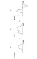
第1の方法は、制御目標となる目標舵角と、操舵角センサ23の出力である実舵角との偏差の絶対値を操舵遅れ量dとするものである。第2の方法は、走行距離と目標旋回曲率との対応を走行距離と目標操舵角との対応に換算し(図8(a))、これと実際の車速変化(図8(b))から、時間当たりの目標操舵速度(図8(c))を求め、これと操舵角センサ23の出力である実舵角の時間変化(微分値)との偏差を求めて、その絶対値を操舵遅れ量dとするものである。第3の方法は、車両の現在位置と設定した走行軌跡との距離(図9参照)を操舵遅れ量dとするものである。
【0051】
操舵遅れ量d算出後、これをしきい値dthと比較する(ステップS19)。操舵遅れ量dがしきい値dth以上の場合には、経路の再設定が必要と判定し、ステップS21へと移行し、第1の制御形態のステップS8と同様の手法によって操舵遅れ量dに基づいて支援制御において利用可能な最大曲率勾配ωmaxを設定する。そして、ステップS10aに戻り、この最大曲率勾配ωmaxの範囲内となるよう移動軌跡を再設定する。制御遅れ量dがしきい値dth未満の場合には、ステップS20へと移行する。この後の処理内容は第1の実施形態と同一であるため、説明を省略する。
【0052】
このように、本制御形態においては、制御遅れ量を測定し、測定した制御遅れ量に基づいて誘導経路を再設定するので、制御遅れの発生状態に合わせて最適な曲率勾配を設定することができるので、目標位置への誘導精度を向上させることができるとともに、誘導経路中で路面μ値が変化する等、操舵負荷が変化し、制御遅れが変動するような状況下においても精度良く誘導を行うことができる。
【0053】
第1の制御形態と第2の制御形態とを組み合わせて、初期経路設定時には、推定した制御遅れ量を用い、再設定時には測定した制御遅れ量を用いて経路設定を行うこともできる。このようにすれば、初期経路、再設定経路とも精度良く誘導を行うことが可能な経路を設定することができる。
【0054】
次に、本実施形態における自車の現在位置推定(ステップS14)の推定処理の詳細を図10〜図15を参照して説明する。図10は、この推定処理の詳細を示すフローチャートであり、図11〜15は、この処理で用いられるフィルタの特性に関するグラフである。
【0055】
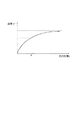
まず、操舵角センサ23の出力から操舵角δを読み取る(ステップS71)。次に、操舵角制御後に目標旋回曲率が実現されるまでの遅れを考慮して現在の旋回曲率を算定する(ステップS72)。具体的には、操舵角δに対する設定曲率γの変化曲線(図11)マップを参照して、操舵角δから設定曲率γを求め、このγの時間変化を図12に示されるような時間フィルタを通過させてその出力値γ’を現在の旋回曲率値とする。ここで、時間フィルタにおける時間遅れ係数τは、路面摩擦係数推定手段47で推定した路面μに応じて図13に示されるように路面μが高いほど時間遅れ係数τが大きくなるよう設定すればよい。あるいは、転舵輪荷重判定手段46の出力である転舵輪荷重Wに応じて図14に示されるように、転舵輪荷重Wが重いほど時間遅れ係数τが大きくなるよう設定すればよい。
【0056】
こうして設定した推定旋回曲率値γ’と車輪速センサ41の出力を基にして推定した車両の移動距離Lから現在の自車位置(x,z)を推定する(ステップS73)。
【0057】
このように操舵角と旋回曲率の間の対応マップから求めた旋回曲率γをそのまま位置推定に用いるのではなく、操舵遅れを考慮した旋回曲率γ’を位置推定に用いるので、タイヤのねじれの影響や転舵機構に含まれる弾性部品の影響、転舵機構自体の弾性変化等に起因するステアリングシャフト21を駆動してから実際に転舵輪25が転舵するまでの時間遅れを考慮した位置推定を行うことができるため、自車位置の推定精度が向上する。このため、自車位置の推定誤差により不要な再設定経路の計算や、再設定経路設定時の誤差の発生を抑制することができる。そのため、移動軌跡の再設定精度を向上させることができ、駐車支援精度が向上する。
【0058】
ここでは、操舵遅れを時間遅れとして考慮する場合を例に説明したが、時間フィルタに代えて、遅れを走行距離の遅れとして出力する距離フィルタを用いることもできる。この距離フィルタの特性は、例えば、図15に示される特性を有する。この距離フィルタにおける走行距離に対する遅れ係数λは、時間フィルタの遅れ係数τと同様に、図13、図14に示されるように路面μや転舵輪荷重Wに応じて設定すればよい。なお、この走行距離に対して操舵遅れを考慮する場合、停止状態で転舵を行う据え切りのように距離に対する操舵速度が速い(据え切りの場合には無限大となる)場合には、実際には短い走行距離のうちに操舵遅れが終了してしまうため適用できない。しかしながら、本発明においては操舵を自動で行うことから、操舵負荷を小さくするため、距離に対する操舵速度は一定速度以下に制限されている。このため、問題となる距離に対する操舵速度が速い場合は制御上除外されているため、時間遅れの場合と同様に適用が可能である。
【0059】
この操舵遅れを考慮した自車位置判定は、前述した第1の制御形態または第2の制御形態と組み合わせて用いることが好ましいが、自車位置判定は操舵遅れを考慮して行い、経路設定、再設定においては操舵遅れを考慮しない形態も可能である。この場合でも、自車位置を精度良く判定することができるため、目標位置への到達精度を向上させることができる。
【0060】
以上の説明では、後退駐車を例に説明したが、前進での駐車支援にも適応可能であるし、駐車支援装置に限らず、経路に応じた移動を自動操舵を用いて誘導する走行支援装置、レーンキープシステム等にも適用可能である。
【0061】
【発明の効果】
以上説明したように本発明によれば、誘導経路の初期設定または再設定の際に、操舵の制御遅れを推定あるいは判定して、推定あるいは判定した制御遅れ量に応じて走行距離に対する曲率変化量を所定の範囲内に制限して誘導経路の設定を行うことにより、自動操舵を用いた誘導中に実際に発生する操舵の遅れを許容範囲内に抑制することができる。これにより、目標位置近傍に到達した際の位置精度が向上する。また、誘導途中で目標位置到達が不能となるケースが発生するのを抑制することができるため、システムに対する信頼性が向上する。
【0062】
また、誘導中の操舵の制御遅れを判定し、この制御遅れを考慮して自車位置判定を行うことにより、自車位置の判定精度が向上する。この位置判定を用いて誘導を行うことで目標位置近傍に到達した際の位置精度が向上する。
【図面の簡単な説明】
【図1】本発明の実施形態である駐車支援装置のブロック構成図である。
【図2】図1の装置における支援動作を説明する図である。
【図3】図1の装置における支援動作の第1の制御形態の制御処理を示すフローチャートである。
【図4】図3の制御における設定走行軌跡を説明する図である。
【図5】操舵遅れ量dに対するこの最大曲率勾配ωmaxの設定曲線の例を示すグラフである。
【図6】目標位置へ誘導しうる初期位置の範囲を示す図である。
【図7】図1の装置における支援動作の第2の制御形態の制御処理を示すフローチャートである。
【図8】操舵角速度から操舵遅れ量を判定する手法について説明する図である。
【図9】走行軌跡のずれから操舵遅れ量を判定する手法について説明する図である。
【図10】図1の装置における自車位置判定処理の詳細を示すフローチャートである。
【図11】操舵角に対する設定曲率の関係を示すグラフである。
【図12】図10の処理で用いられる時間フィルタの特性を示すグラフである。
【図13】図12の時間フィルタの時間遅れ係数τを路面μに応じて設定する場合の設定例を示すグラフである。
【図14】図12の時間フィルタの時間遅れ係数τを転舵輪荷重Wに応じて設定する場合の設定例を示すグラフである。
【図15】図10の処理で用いられる距離フィルタの特性を示すグラフである。
【符号の説明】
1…駐車支援ECU、10…画像処理部、11…操舵制御部、12…演算手段、20…自動操舵装置、21…ステアリングシャフト、22…ステアリングホイール、23…操舵角センサ、24…操舵アクチュエータ、25…転舵輪、31…入力手段、32…後方カメラ、33…スピーカー、34…モニタ、41…車輪速センサ、43…加速度センサ、44…タイヤ空気圧測定装置、46…転舵輪荷重判定手段、47…路面摩擦係数推定手段、51…車高センサ、52…着座センサ、100…駐車支援装置、110…操舵遅れ判定手段。[0001]
TECHNICAL FIELD OF THE INVENTION
BACKGROUND OF THE INVENTION 1. Field of the Invention The present invention relates to a vehicular travel support device that obtains a travel locus to a target position and assists the vehicle in traveling so that the vehicle follows the travel locus, and more particularly to a vehicular travel support device that guides the vehicle by automatic steering. About.
[0002]
[Prior art]
A technique for guiding a vehicle to a target position by using automatic steering or a steering instruction is known (for example, see Patent Document 1). For example, when the loaded weight of the vehicle changes, the geometry of the suspension changes, so that the turning angle of the wheel with respect to the steering angle of the steering wheel changes. In order to make the movement trajectory of the vehicle always coincide even if such a change in the geometry of the suspension occurs, in the technique of Patent Document 1, it is determined whether or not the relationship between the moving distances of the left and right front wheels is a predetermined relationship. It is described that when the relationship is not satisfied, the vehicle can be correctly guided to the target position by correcting the movement trajectory according to the deviation.
[0003]
[Patent Document 1]
JP 2001-63599 A (paragraphs 0021 to 0032, FIGS. 4 and 9)
[0004]
[Problems to be solved by the invention]
By the way, when route guidance is performed using an automatic steering device, the travel distance and the curvature are used for the route determination. Usually, the steering angle and the wheel rotation speed are used to determine these. However, when the steering load changes due to a change in the loaded weight of the vehicle or the like, the output of the automatic steering driving device (such as an electric motor) needs to be increased to perform the same steering. If so, there will be a delay in steering. Due to this steering delay, the estimation accuracy of the current vehicle position itself is reduced. In addition, even if the route is reset, a deviation may occur from the reset route due to the steering delay.
[0005]
Accordingly, it is an object of the present invention to provide a vehicular traveling support device using an automatic steering device capable of suppressing a decrease in the accuracy of route guidance due to a steering delay.
[0006]
[Means for Solving the Problems]
In order to solve the above-mentioned problems, a vehicle driving support device according to the present invention sets a target route to a target position and performs steering by an automatic steering device, thereby guiding a vehicle along the target route. The driving support device includes a control delay determining unit that determines a delay of the steering control with respect to a target value, determines a maximum curvature gradient of the target path in consideration of the determined control delay, and determines the maximum curvature gradient determined by the curvature gradient. Is set, and guidance is performed by setting a target route within the range.
[0007]
The steering delay increases as the steering speed (the rotation speed of the steering wheel or the steering shaft per time) increases. Therefore, by limiting the steering speed, it is possible to suppress a steering delay that actually occurs. According to the present invention, a route in which the steering speed does not reach a predetermined speed or more is selected by changing the use range of the curvature gradient, which is the amount of change in the turning curvature with respect to the traveling distance, in accordance with the state of the steering delay. Suppress.
[0008]
When resetting the target route during the guidance, it is preferable to reset the route using the control delay measured during the guidance. As a result, even if the vehicle deviates from the initial target route due to a steering delay, the reset route is selected in consideration of the steering delay, so that the deviation from the target route after the reset can be suppressed, and the target position can be reliably maintained. Can be reached.
[0009]
The resetting of the target route may be performed when the determined steering delay amount reaches a predetermined value or more. In such a case, while the deviation from the route increases, the route to the target route can be reset with accuracy by considering the delay.
[0010]
The control delay determining means may determine the control delay based on a deviation between the target steering angle and the actual steering angle, a deviation between the target steering speed and the actual steering speed, a deviation between the target route and the actual vehicle position, and the like. From these, the control delay can be accurately determined.
[0011]
Here, when determining the vehicle position, it is preferable to estimate a change in the turning curvature with respect to the steering angle in consideration of the control delay, and to estimate the actual vehicle position using the estimated turning curvature change. Thereby, the estimation accuracy of the vehicle position is improved.
[0012]
The control delay determining means may determine a control delay from the steering load, and the steering load is estimated using at least one of a road surface condition, a steered wheel load, a tire pressure, and a load of an automatic steering device. Is preferred. From these, the control delay can be accurately determined.
[0013]
The vehicle driving support device according to the present invention sets a target route to a target position, and performs steering by an automatic steering device, so that the vehicle driving support device guides the vehicle along the target route. In consideration of the above, a change in the turning curvature with respect to the steering angle may be estimated, and the current position of the host vehicle may be estimated based on the estimated turning curvature change.
[0014]
As a result, the current position of the vehicle can be accurately estimated, so that route setting and guidance can be reliably performed.
[0015]
This control delay is preferable because it is easy to handle when it is estimated as a time delay with respect to the steering amount or a delay with respect to the traveling distance of the steering amount. This control delay may be determined on the basis of the road surface condition and the steered wheel load.
[0016]
BEST MODE FOR CARRYING OUT THE INVENTION
Hereinafter, preferred embodiments of the present invention will be described in detail with reference to the accompanying drawings. In order to facilitate understanding of the description, the same components are denoted by the same reference numerals as much as possible in each drawing, and redundant description is omitted.
[0017]
Hereinafter, a parking assist device will be described as an example of the driving assist device according to the present invention. FIG. 1 is a block configuration diagram of a parking assistance device 100 according to an embodiment of the present invention. The parking assist device 100 includes an automatic steering device 20 and is controlled by a parking assist ECU 1 as a control device. The parking assist ECU 1 includes a CPU, a ROM, a RAM, an input signal circuit, an output signal circuit, a power supply circuit, and the like. The image processing unit 10 processes an image acquired by a rear camera 32 described below, and an automatic steering device. And a steering control unit 11 for performing the above control. The steering control unit 11 is provided with a steering delay determination unit 110. The image processing unit 10 and the steering control unit 11 may be divided in hardware in the parking assist ECU 1, but may be divided in software using a common CPU, ROM, RAM and the like. The steering delay judging means 110 of the steering control unit 11 may be hardware-separated from other parts of the steering control unit 11 in the parking assist ECU 1, but may use a common CPU, ROM, RAM, or the like to implement software. May be classified.
[0018]
The steering shaft 21 that transmits the movement of the steering wheel 22 to the steered wheels 25 is connected to a steering angle sensor 23 that detects a steering amount of the steering shaft 21 and a steering actuator 24 that applies a steering force. Here, the steering actuator 24 may also serve as a power steering device that applies an assist steering force when the driver steers, in addition to applying the steering force during automatic steering. The steering actuator 24 has an electric motor, and the steering control unit 11 controls driving of the steering actuator 24. The steering delay determining means 110 monitors the operating current of the steering actuator 24 and receives an output signal of the steering angle sensor 23. This output signal is also sent to the steering control unit 11.
[0019]
In addition to the output of the steering angle sensor 23, the outputs of the wheel speed sensors 41 arranged on each wheel to detect the wheel speed and the outputs of the acceleration sensor 42 for detecting the acceleration of the vehicle are input to the steering control unit 11. ing. On the other hand, the output of the tire pressure measuring device 44 is input to the steering delay determining means 110. As the tire pressure measuring device 44, a sensor for directly detecting the air pressure inside the tire is provided in the wheel portion of each wheel, and the output is transmitted wirelessly, and is received and output by the receiving portion disposed in the vehicle body, and the direct measurement system is provided. An indirect measurement method that converts a change in the resonance frequency of the tire into a change in the spring constant based on the output of the wheel speed sensor 41 and detects the change in the air pressure can be used.
[0020]
Further, the output of the steered wheel load determining unit 46 is input to the steering delay determining unit 110. The output of the vehicle height sensor 51 for detecting a change in the vehicle height at the front part (the steered wheel side) of the vehicle, and the output of a seating sensor 52 for detecting the driver's seat and the passenger's seat are input to the steered wheel load determining means 46. ing. The output of the road friction coefficient estimating means 47 is also input to the steering delay determining means 110. The road surface friction coefficient estimating means 47 can use a method of detecting from the rotation state of the drive wheel based on the output of the wheel speed sensor 41 or the like.
[0021]
The above-described image processing unit 10 of the parking assist ECU 1 receives an image signal which is an output signal of the rear camera 32 which is disposed at the rear of the vehicle and acquires a rear image. The input means 31 for accepting, a monitor 34 for displaying information to a driver by an image, and a speaker 33 for presenting information by voice are connected.
[0022]
Next, a support operation in the parking support device will be specifically described. In the following, as shown in FIG. 2, a description will be given of a support operation in a case where the vehicle 200 is accommodated by retreating in a garage 220 provided facing the road 210, that is, in a garage. FIG. 3 is a flowchart showing a control process of the first control mode of the support operation, and FIG. 4 is a diagram for explaining a set traveling locus in this control.
[0023]
The control shown in FIG. 3 is performed after the driver operates the input means 31 to instruct the parking assist ECU 1 to start the parking assist control until the vehicle reaches the vicinity of the instructed target parking position or the target parking position. Unless the driver cancels the assisting operation from the input unit 31, the parking assist ECU 1 continues to execute the operation until it is determined that the vehicle cannot be reached by one retreat.
[0024]
Specifically, the driver uses the reference point of the vehicle 200 (in the following description, the axle center of the rear wheel of the vehicle will be described as the reference point. Of course, other positions, such as the center of the rear end of the vehicle and the center of gravity, After the vehicle 200 is moved so that the front end or the rear end on one side may be the reference point) (the vehicle at this position is represented by 200a) so as to coincide with the point A in FIG. Instructs the start of the parking assist operation. The driver operates the input means 31 while watching the image captured by the rear camera 32 displayed on the monitor 34, thereby moving the parking frame displayed on the screen to move to the target parking position. Then, the target parking position is set (step S2).
[0025]
The parking assist ECU 1 obtains the vehicle position 200g at the target parking position, specifically, the position of the reference point G, and the direction of the vehicle at that position by image recognition processing (step S4). The position of the point G may be obtained, for example, as relative coordinates with respect to the reference point A at the current vehicle position. Hereinafter, as shown in FIG. 2, a description will be given using a coordinate system in which the target position G is set as the origin, the vehicle at the target position is set in the z-axis direction, and the direction orthogonal to the z-axis is set in the x-axis. The angle between the current vehicle direction and the z-axis is defined as a deflection angle θ (the deflection angle at the initial position is defined as θ 0 And ).
[0026]
Next, a steering delay occurring during the support control is estimated from the current vehicle state quantity (step S6). In the present embodiment, a route is set by associating a turning distance with a turning curvature as described later. Then, in order to obtain a desired turning curvature, control for changing the steering angle by the steering actuator 24 is performed. Here, the steering delay refers to a period from when the steering shaft 21 is driven by the steering actuator 24 to when the steered wheels 25 are turned to reach a predetermined turning curvature (the predetermined turning curvature is a set curvature described above. (It may be different from the desired turning curvature.), And can be expressed as a time delay, for example.
[0027]
The determination of the steering delay is performed by the steering delay determining means 110, and the magnitude of the steering load is estimated based on the following vehicle state quantity, and the steering delay is determined based on the estimated steering load. Of course, the correspondence between the vehicle state quantity and the steering delay may be grasped, and the steering delay may be directly obtained from a predetermined vehicle state quantity.
[0028]
In the first method, the road surface friction coefficient μ of the road 210 when the road 210 is moved from the front of the garage 220 to the point A is estimated by the road surface friction coefficient estimating means 47. It is determined that the load increases and the steering delay increases.
[0029]
The second method is based on the steered wheel load. The steered wheel load is determined by the steered wheel load determining means 46, and is determined by the front wheel measured by the vehicle height sensor 51, that is, when the vehicle height on the steered wheel 25 side decreases, or by the measurement result of the seating sensor 52. From this, it is determined that the load is applied to the steered wheels 25 when the driver is on the front seat (driver's seat and front passenger seat), the steering load during support increases, and the steering delay increases. Here, the case where both the vehicle height sensor 51 and the seating sensor 52 are used has been described. However, only one of the vehicle height sensor 51 and the seating sensor 52 may be used. Since the influence of the driver is small and the driver is always in the vehicle, the estimation can be performed based on the sitting state of only the passenger seat.
[0030]
The third method is based on the tire air pressure of the steered wheels 25 measured by the air pressure measuring device 44. Since the steering load increases as the tire air pressure decreases, it is estimated that the steering delay increases.
[0031]
The fourth method is based on the assist current of the electric motor constituting the steering actuator 24. This is because the assist current is measured when the assist steering force is applied by the electric motor in accordance with the driver's steering before the assistance starts, for example, when the vehicle moves from the front of the garage 220 to the point A on the road 210, and the assist current is measured. When the current is large, it is assumed that the steering load is large, and it is estimated that the steering delay becomes large even during the assist control.
[0032]
In estimating the steering delay amount, any one or a combination of these four methods can be performed. If a plurality of methods are combined so as to correspond to a plurality of parameters affecting the steering load, a more accurate estimation of the steering delay can be performed. However, when only one method is used, the steering delay can be reduced by a simple method. There are advantages that can be estimated.
[0033]
After estimating the steering delay, a maximum curvature gradient that can be used in the parking assist control is set based on the steering delay (step S8). The maximum curvature gradient indicates the maximum value of the amount of change in the turning curvature with respect to the traveling distance. FIG. 5 is a graph illustrating an example of a setting curve of the maximum curvature gradient ωmax with respect to the steering delay amount d. By decreasing the maximum curvature gradient ωmax as the steering delay amount d increases, the steering delay that actually occurs in the control can be suppressed to a predetermined amount or less. As shown by the solid line in FIG. 5, this setting curve indicates the decrease in the maximum curvature gradient ωmax with respect to the increase in the steering delay d when the steering delay d is small, and the steering delay when the steering delay d is large. The maximum curvature gradient ωmax may be set to be greater than the decrease amount of the maximum curvature gradient ωmax with respect to the increase amount of d. Good.
[0034]
Next, the guidance route P from the current position A to the target position G within the range of the set maximum curvature gradient ωmax. 0 Is calculated (step S10). Hereinafter, a case where the initial steering angle is in a neutral state will be described as an example. This guidance route P 0 Are a process of retreating in a neutral steering angle state (process 1), a process of increasing the steering angle (process 2), a process of maintaining the steering angle in the increased state (process 3), and a process of neutralizing the steering angle. There are five steps: a returning step (step 4) and a step of retreating while maintaining the steering angle neutral state (step 5). In steps 2 and 4, the amount of change in the turning curvature with respect to the traveling distance (change in the turning curvature) The absolute value of (velocity) is set to be equal to or less than the set maximum curvature gradient ωmax (actually, it is made to match ωmax).
[0035]
A typical example of the trajectory set in this manner is as follows: from point A to point B, the vehicle retreats in a steering neutral state (step 1), and from point B to point C, the turning curvature changes at a rate of change of ωmax and increases the turning curvature. Then, at point C, the state changes to a state where the turning curvature has the set maximum value γmax and the turning radius has the set minimum turning radius (Rmin = 1 / γmax) (step 2). The turning curvature and the turning radius are maintained from the point C to the point D (step 3). Conversely, the change rate of the turning curvature is set to -ωmax from the point D, the turning curvature is reduced, and a transition is made to the neutral state of the steering angle 0 at the point E (step 4). Then, from point E to point G, the vehicle retreats in this neutral state (step 5).
As a result, the traveling locus P 0 Is a circular arc having a radius Rmin (curvature γmax) between AB and EG, and a radius Rmin (curvature γmax) between CDs, and a clothoid curve having a curvature γmax at one end and zero curvature at the other end between BC and DE. When the deflection angle θ is small or when the distance between the AGs is short, there may be a case where one or a plurality of processes are not provided. Here, the change amount Δθ of the deflection angle θ can be expressed by Δθ = ∫δdp. That is, the change amount Δθ of the deflection angle is determined by the area S of the traveling locus shown in FIG. 0 Matches.
[0036]
Next, it is determined whether a route has been set (step S12). If the target position G cannot be reached from the current position A even if the maximum turning curvature ωmax is maintained, and it is determined that the route cannot be set, the process proceeds to step S50, and the target position G is reached from the current position A. The driver is informed of the inability to use the monitor 34 or the speaker 33, and the process ends. If necessary, the driver may move the vehicle 200 and activate the parking assist operation again.
[0037]
If the target route has been set, the process moves to step S14, and moves to actual support control. Here, when the shift lever is set to the reverse position, it is preferable that the parking assist ECU 1 instructs a drive system (not shown) to perform an engine torque-up control. In the torque-up control, the engine is rotated at a higher rotation speed than during normal idling, thereby shifting to a state where the driving force is high (torque-up state). . As a result, the vehicle speed range that can be adjusted only by the brake pedal without the driver performing the accelerator operation is expanded, and the controllability of the vehicle is improved. When the driver operates the brake pedal, the vehicle speed is adjusted by adjusting the braking force applied to each wheel according to the pedal opening. At this time, it is preferable to perform the guard of the upper limit vehicle speed by controlling the braking force applied to each wheel so that the vehicle speed detected by the wheel speed sensor 32 does not exceed the upper limit vehicle speed.
[0038]
In the guidance control, first, the current position of the vehicle is determined (step S14). This current position determination can be made based on the movement of a feature point in an image captured by the rear camera 32, and can be performed based on a travel distance change based on the output of the wheel speed sensor 41 or the acceleration sensor 42. The determination may be made based on a change in the steering angle based on the output of the steering angle sensor 23.
[0039]
Then, the actual steering angle control is performed based on the set trajectory of the travel distance-the steering angle previously set based on the current position (the travel distance) (step S16). Specifically, the steering control unit 11 controls the steering actuator 24 to drive the steering shaft 21 and roll the steered wheels 25 while monitoring the output of the steering angle sensor 23, so that the set turning curvature is reduced. Control to be realized.
[0040]
In the present embodiment, since the maximum value of the absolute value of the curvature gradient used in the support control is limited to the set value ωmax or less, in the garage parking operation, as shown in FIG. 6, the vehicle can be guided to the target position. The range N of the initial position is shifted in a direction closer to the z-axis as compared with the range M when no restriction is performed. As a result, the initial position where the target route can be set is limited, and the number of cases where the route cannot be set from the initial position increases. However, when the region of the range M outside the range N is set as the initial position, when a steering delay occurs in the actual control, it is difficult to guide to the target position therefrom. It is necessary to perform the movement.
[0041]
According to the present embodiment, the maximum curvature gradient ωmax that can be used when setting a route is limited according to the steering delay amount d. Since the upper limit speed at the time of assistance is specified, by limiting the maximum curvature gradient ωmax, the upper limit value of the steering speed is also restricted, and the steering speed can be reduced. As a result, it is possible to suppress the steering delay amount that actually occurs in the automatic steering control. For this reason, when the initial position is located within the range N and the vehicle can reach the target position without fail, the route can be set, and the position accuracy in parking assistance can be ensured. Therefore, the operability of parking assistance is improved. Furthermore, since the curvature gradient to be used is not always set to be small, but the maximum curvature gradient ωmax is set according to the steering delay amount, it is possible to use an appropriate curvature gradient according to the road surface state and the vehicle state, The initial position where the guidance is possible is not unnecessarily limited.
[0042]
Since the vehicle travels along the route set in this way, the driver can concentrate on the safety check on the course and the vehicle speed adjustment. When an obstacle or a pedestrian is present on the course, when the driver depresses the brake pedal, a braking force corresponding thereto is applied to each wheel, so that the vehicle can be safely decelerated and stopped.
[0043]
After the steering angle control, it is determined whether or not the current position is shifted from the target route. If the current position is large, it is determined that the route needs to be corrected (step S18). The deviation from the target route can be obtained by integrating the deviation between the target position and the current position or the deviation between the target steering amount and the actual steering amount with respect to the traveling distance. If the route needs to be corrected, the process returns to step S10 to reset the route.
[0044]
On the other hand, if the deviation from the target route is small, the process proceeds to step S20, and it is determined whether the vehicle has reached the vicinity of the target parking position G. If the vehicle has not reached the target parking position, the process returns to step S14 to continue the support control. If it is determined that the vehicle has reached the target parking position, the process proceeds to step S22, and the driver is notified by the monitor 34 and the speaker 33 that the vehicle has reached the target parking position, and the process ends.
[0045]
Here, the case of garage storage has been described as an example, but the case of parallel parking can be handled by combining garage storage logic. Limiting the maximum curvature gradient requires a longer parking space than in the case without limitation, but in this case also, the route setting can be performed reliably and the advantage of improving the parking position accuracy is common.
[0046]
Subsequently, a second control mode of the assisting operation in the parking assist device will be described with reference to the processing flow of FIG. This control mode is different from the first control mode in that the initial route setting does not consider the steering delay, and performs the route setting in consideration of the steering delay at the time of recalculation.
[0047]
Specifically, the processing in steps S2 and S4 is the same as in the first control mode. Thereafter, the maximum curvature gradient ωmax is changed to a constant value ω that is equal to or smaller than the curvature gradient possible when the steering actuator 24 is operated at the maximum steering speed when the vehicle speed is the upper limit speed at the time of guidance. 0 In the state described above, the guidance route P from the current position A to the target position G by the same method as in step S10. 0 Is calculated (step S10a).
[0048]
The process of determining whether or not the route has been set (step S12), the process when the route cannot be set (step S50), and the process of route guidance (steps S14 and S16) are the same as those in the first control mode.
[0049]
After step S16, the current steering delay d is calculated (step S17). The steering delay amount d is calculated by the steering delay determining means 110 in the following manner.
[0050]
In the first method, the absolute value of the deviation between the target steering angle serving as the control target and the actual steering angle output from the steering angle sensor 23 is used as the steering delay amount d. In the second method, the correspondence between the traveling distance and the target turning curvature is converted into the correspondence between the traveling distance and the target steering angle (FIG. 8A), and from this and the actual vehicle speed change (FIG. 8B). The target steering speed per time (FIG. 8 (c)) is obtained, and the deviation between this and the time change (differential value) of the actual steering angle which is the output of the steering angle sensor 23 is obtained. The quantity is d. In the third method, the distance between the current position of the vehicle and the set traveling locus (see FIG. 9) is used as the steering delay amount d.
[0051]
After calculating the steering delay amount d, this is compared with a threshold value dth (step S19). If the steering delay d is equal to or larger than the threshold value dth, it is determined that the route needs to be reset, and the process proceeds to step S21, where the steering delay d is reduced by the same method as in step S8 of the first control mode. The maximum curvature gradient ωmax usable in the support control is set based on the control. Then, the process returns to step S10a, and the movement locus is reset so as to be within the range of the maximum curvature gradient ωmax. If the control delay amount d is less than the threshold value dth, the process proceeds to step S20. Subsequent processing is the same as in the first embodiment, and a description thereof will not be repeated.
[0052]
As described above, in the present control mode, the control delay amount is measured, and the guidance route is reset based on the measured control delay amount. Therefore, it is possible to set the optimum curvature gradient in accordance with the control delay occurrence state. As a result, guidance accuracy to the target position can be improved, and guidance can be accurately performed even under conditions where the steering load changes, such as when the road μ value changes in the guidance route, and the control delay fluctuates. It can be carried out.
[0053]
By combining the first control mode and the second control mode, the route can be set using the estimated control delay amount when setting the initial route and using the measured control delay amount when resetting. In this way, it is possible to set a route that can provide guidance with high accuracy for both the initial route and the reset route.
[0054]
Next, details of the estimation process of the current position estimation of the own vehicle (step S14) in the present embodiment will be described with reference to FIGS. FIG. 10 is a flowchart showing details of this estimation processing, and FIGS. 11 to 15 are graphs relating to the characteristics of the filters used in this processing.
[0055]
First, the steering angle δ is read from the output of the steering angle sensor 23 (step S71). Next, the current turning curvature is calculated in consideration of a delay until the target turning curvature is realized after the steering angle control (step S72). Specifically, a set curvature γ is obtained from the steering angle δ with reference to a map of a change curve (FIG. 11) of the set curvature γ with respect to the steering angle δ. And the output value γ ′ is set as the current turning curvature value. Here, the time delay coefficient τ in the time filter may be set according to the road surface μ estimated by the road surface friction coefficient estimating means 47 so that the time delay coefficient τ increases as the road surface μ increases, as shown in FIG. . Alternatively, the time delay coefficient τ may be set to be larger as the steered wheel load W is larger, as shown in FIG. 14, according to the steered wheel load W which is the output of the steered wheel load determining means 46.
[0056]
The current vehicle position (x, z) is estimated from the estimated moving distance L of the vehicle based on the estimated turning curvature value γ ′ thus set and the output of the wheel speed sensor 41 (step S73).
[0057]
In this way, the turning curvature γ ', which takes into account the steering delay, is used for position estimation instead of using the turning curvature γ obtained from the correspondence map between the steering angle and the turning curvature as it is for position estimation. Position estimation taking into account the time delay from the driving of the steering shaft 21 to the actual turning of the steered wheels 25 due to the influence of the elastic components included in the steering mechanism and the elasticity change of the steering mechanism itself. Since this can be performed, the accuracy of estimating the position of the own vehicle is improved. For this reason, it is possible to suppress the calculation of an unnecessary reset route due to the estimation error of the own vehicle position and the occurrence of an error when setting the reset route. Therefore, the accuracy of resetting the movement trajectory can be improved, and the accuracy of parking assistance is improved.
[0058]
Here, the case where the steering delay is considered as a time delay has been described as an example, but a distance filter that outputs the delay as a delay of the traveling distance may be used instead of the time filter. The characteristics of this distance filter have, for example, the characteristics shown in FIG. The delay coefficient λ for the traveling distance in this distance filter may be set according to the road surface μ and the steered wheel load W as shown in FIGS. When the steering delay is taken into consideration for this traveling distance, when the steering speed with respect to the distance is fast (infinite in the case of stationary steering) as in the case of stationary steering in which the steering is stopped, the actual Is not applicable because the steering delay ends within a short traveling distance. However, in the present invention, since the steering is performed automatically, the steering speed with respect to the distance is limited to a certain speed or less in order to reduce the steering load. For this reason, the case where the steering speed is high for the distance in question is excluded from the control, so that it can be applied similarly to the case of the time delay.
[0059]
It is preferable to use the own vehicle position determination in consideration of the steering delay in combination with the first control mode or the second control mode described above. However, the own vehicle position determination is performed in consideration of the steering delay, and route setting, In the resetting, a mode in which the steering delay is not considered is also possible. Even in this case, since the position of the own vehicle can be determined with high accuracy, the accuracy of reaching the target position can be improved.
[0060]
In the above description, the reverse parking was described as an example, but the present invention is also applicable to parking assistance in a forward direction, and is not limited to a parking assistance device, and a traveling assistance device that guides movement according to a route using automatic steering. And a lane keeping system.
[0061]
【The invention's effect】
As described above, according to the present invention, at the time of initial setting or resetting of the guidance route, the control delay of the steering is estimated or determined, and the curvature change amount with respect to the traveling distance is determined according to the estimated or determined control delay amount. Is set within a predetermined range, and the guidance route is set, whereby the steering delay that actually occurs during the guidance using the automatic steering can be suppressed to an allowable range. As a result, the position accuracy when reaching the vicinity of the target position is improved. In addition, since it is possible to suppress a case where the target position cannot be reached during the guidance, the reliability of the system is improved.
[0062]
In addition, the control accuracy of the vehicle position is improved by determining the control delay of the steering during the guidance and performing the vehicle position determination in consideration of the control delay. By performing guidance using this position determination, the position accuracy when reaching the vicinity of the target position is improved.
[Brief description of the drawings]
FIG. 1 is a block diagram of a parking assist device according to an embodiment of the present invention.
FIG. 2 is a diagram for explaining a support operation in the apparatus of FIG.
FIG. 3 is a flowchart showing a control process of a first control mode of the support operation in the apparatus of FIG. 1;
FIG. 4 is a diagram illustrating a set traveling locus in the control of FIG. 3;
FIG. 5 is a graph showing an example of a setting curve of the maximum curvature gradient ωmax with respect to a steering delay amount d.
FIG. 6 is a diagram illustrating a range of an initial position that can be guided to a target position.
FIG. 7 is a flowchart illustrating a control process of a second control mode of the support operation in the apparatus of FIG. 1;
FIG. 8 is a diagram illustrating a method of determining a steering delay amount from a steering angular velocity.
FIG. 9 is a diagram illustrating a method of determining a steering delay amount from a deviation of a traveling locus.
FIG. 10 is a flowchart illustrating details of a host vehicle position determination process in the apparatus of FIG. 1;
FIG. 11 is a graph showing a relationship between a set curvature and a steering angle.
FIG. 12 is a graph showing characteristics of a time filter used in the processing of FIG. 10;
13 is a graph showing a setting example in a case where a time delay coefficient τ of the time filter in FIG. 12 is set according to a road surface μ.
14 is a graph showing a setting example in a case where a time delay coefficient τ of the time filter in FIG. 12 is set according to a steered wheel load W.
FIG. 15 is a graph showing characteristics of a distance filter used in the processing of FIG. 10;
[Explanation of symbols]
DESCRIPTION OF SYMBOLS 1 ... Parking assistance ECU, 10 ... Image processing part, 11 ... Steering control part, 12 ... Calculation means, 20 ... Automatic steering device, 21 ... Steering shaft, 22 ... Steering wheel, 23 ... Steering angle sensor, 24 ... Steering actuator, 25: steered wheels, 31: input means, 32: rear camera, 33: speaker, 34: monitor, 41: wheel speed sensor, 43: acceleration sensor, 44: tire pressure measuring device, 46: steered wheel load determining means, 47 ... road surface friction coefficient estimating means, 51 ... vehicle height sensor, 52 ... seating sensor, 100 ... parking assist device, 110 ... steering delay determination means.