JP2004338517A - Vehicle device control device - Google Patents
Vehicle device control device Download PDFInfo
- Publication number
- JP2004338517A JP2004338517A JP2003136777A JP2003136777A JP2004338517A JP 2004338517 A JP2004338517 A JP 2004338517A JP 2003136777 A JP2003136777 A JP 2003136777A JP 2003136777 A JP2003136777 A JP 2003136777A JP 2004338517 A JP2004338517 A JP 2004338517A
- Authority
- JP
- Japan
- Prior art keywords
- head
- occupant
- physique
- detected
- vehicle
- Prior art date
- Legal status (The legal status is an assumption and is not a legal conclusion. Google has not performed a legal analysis and makes no representation as to the accuracy of the status listed.)
- Granted
Links
Images


Abstract
Description
【0001】
【発明の属する技術分野】
本発明は、車室内をカメラで撮影するとともに撮影画像に基づいて乗員頭部に関する情報を検出して、同頭部の検出結果に応じて車両デバイスを制御する車両デバイス制御装置に関する。
【0002】
【従来の技術】
従来から、カメラで撮影した車室内の画像に基づいて、乗員の存在の有無、乗員頭部の位置を検出することにより乗員の着座姿勢、乗員とインストルメントパネルとの距離などを検出して、これらの検出結果に応じてエアバックの作動の有無を制御することは知られている(特許文献1参照)。
【0003】
【特許文献1】
特開2001−331790号公報
【0004】
【発明が解決しようとする課題】
しかし、上記従来例のように乗員頭部の位置を表す情報のみによりエアバック装置を含む車両デバイスを制御したのでは不充分である。すなわち、シートに着座している乗員は通常の大人であったり、小柄の大人であったり、子供であったりする。この場合、乗員を保護するためには、乗員に応じてエアバックの展開態様を変更することが好ましいが、上記従来装置では乗員に応じてエアバックの展開態様を換えることはできず、エアバック装置の制御が必ずしも適切ではない。
【0005】
【発明の概要】
本発明は、上記問題に対処するためになされたもので、その目的は、エアバック装置を含む、シートベルト装置、ミラー装置、情報表示装置、ヘッドレスト装置、シートベルトウォーニング装置およびオーディオ装置などの車両デバイスを適切に制御する車両デバイス制御装置を提供するものである。
【0006】
上記目的を達成するために、本発明の特徴は、車室内の画像を撮影するカメラと、前記撮影された画像から乗員頭部に関する情報を検出する頭部検出手段と、乗員の体格を検出する体格検出手段と、前記検出した乗員頭部情報および体格に応じて車両デバイスを制御するデバイス制御手段とを備えたことにある。この場合、車両デバイスとは、例えば、シートベルト巻取り装置を含むシートベルト装置、エアバック装置などである。
【0007】
これによれば、デバイス制御手段は、乗員頭部に関する情報および乗員の体格に応じて車両デバイスを制御するので、車両デバイスが適切に制御される。
【0008】
また、前記本発明において、頭部検出手段は乗員頭部の存在の有無を頭部情報として検出する頭部存在検出手段を含み、車両デバイスは車両衝突時に乗員を拘束する拘束装置であり、デバイス制御手段は、頭部存在検出手段によって乗員頭部が存在しないことが検出されたとき拘束装置の作動を禁止し、頭部存在検出手段によって乗員頭部が存在することが検出されたとき拘束装置の作動を許容するとともに、同拘束装置の作動態様を前記検出された体格に応じて制御するようにするとよい。この場合も、拘束装置とは、例えばシートベルト巻取り装置を含むシートベルト装置、エアバック装置などである。
【0009】
これによれば、不必要な拘束装置の作動を避けることができ、前記作動後の修理費を低減できるとともに、無駄な電力消費を抑えることができる。また、拘束装置は、乗員の体格に応じて適切に制御される。
【0010】
また、前記本発明において、車両デバイスはシートベルト巻取り装置であり、デバイス制御手段はシートベルト巻取り装置の作動時におけるシートベルトの張力を前記検出した体格に応じて制御するようにするとよい。
【0011】
これによれば、車両の衝突予知時、衝突時などに作動するシートベルト巻取り装置が、通常の大人、小柄な大人、子供などのように乗員の体格に応じて異なる張力をシートベルトに付与する。したがって、適切な張力を有するシートベルトで乗員を拘束できるようになり、乗員を適切に保護できる。
【0012】
また、前記本発明において、車両デバイスはエアバック装置であり、デバイス制御手段はエアバック装置の作動時におけるエアバックの展開態様を前記検出された乗員の体格に応じて制御するようにするとよい。
【0013】
これによれば、車両の衝突予知時に展開されるエアバックの展開態様が、通常の大人、小柄な大人、子供などのように乗員の体格に応じて制御される。したがって、乗員を適切に保護できる。
【0014】
また、前記本発明において、頭部検出手段は、さらに乗員頭部からエアバックまでの距離を頭部情報として検出する頭部距離検出手段を含み、デバイス制御手段は、エアバックの展開態様を前記乗員の体格に加えて前記検出された距離に応じて制御するようにするとよい。
【0015】
これによれば、エアバックの展開態様が、乗員頭部からエアバックまでの距離に応じても制御されて、エアバックが車両衝突時の状況に応じて的確に展開するようになり、乗員をより適切に保護できる。
【0016】
また、前記本発明において、さらに、シートベルトの装着を検出する装着検出手段と、前記車両デバイスとは独立して設けられ、シートベルトの装着を乗員に警告するためのウォーニング装置とを備え、頭部検出手段は乗員頭部の存在の有無を頭部情報として検出する頭部存在検出手段を含み、デバイス制御手段は、さらに、頭部存在検出手段によって乗員頭部が存在することが検出され、かつ装着検出手段によってシートベルトの装着が検出されないとき、ウォーニング装置を作動させるようにするとよい。
【0017】
これによれば、シートに物が置かれている場合は除外され、シートに乗員が着座し、かつ乗員がシートベルトを装着していないときのみ、シートベルトの装着が乗員に警告されるので、不必要な警告が回避される。
【0018】
また、前記本発明において、さらに、前記車両デバイスとは独立して設けられ、乗員頭部の位置によって位置変更を必要とする他の車両デバイスを備え、記頭部検出手段は、乗員頭部の位置を頭部情報として検出する頭部位置検出手段を含み、デバイス制御手段は、さらに前記検出した乗員頭部の位置に応じて前記他の車両デバイスを制御するようにするとよい。この場合、他の車両デバイスは、例えば、後方確認用ミラーを有するミラー装置、乗員に対して各種情報を画像表示する情報表示装置、ヘッドレストの高さを調整可能なヘッドレスト装置、風向きを変更可能なエアーコンディショナー装置、音場を変更可能なオーディオ装置などである。
【0019】
これによれば、乗員が乗員頭部の位置に従って位置変更を必要とする車両デバイスを手動で操作しなくても、同車両デバイスの位置が自動的に変更されるので、乗員にとって便利になる。
【0020】
さらに、この場合には、前記他の車両デバイスは車両後方を確認するためのミラーであり、さらに車両の前進を検出する前進検出手段を備え、デバイス制御手段は、前記前進検出手段によって車両の前進が検出されたとき、ミラーの位置を前記検出した乗員頭部の位置に応じて制御するようにするとよい。
【0021】
これによれば、不必要なミラーの作動を抑えることができ、消費電力を節約できる。
【0022】
また、前記本発明においては、頭部検出手段は乗員頭部の位置を頭部情報として検出する頭部位置検出手段を含み、体格検出手段を、シートに加わる荷重を乗員の体格として検出する荷重センサと、前記検出された荷重が乗員の体格を表しているかを前記検出された乗員頭部の位置に基づいて判定する判定手段と、前記検出された荷重が乗員の体格を表していると判定手段によって判定されたとき、乗員の体格を表す体格データを同検出された荷重に更新し、かつ前記検出された荷重が乗員の体格を表していると判定手段によって判定されないとき、前記体格データを更新しないで以前の値に維持する体格データ更新手段とで構成するとよい。
【0023】
乗員がドア側にもたれ、また体の一部をインストルメントパネルに載せるなど、シート以外の部位で乗員の体重を支えているような姿勢を乗員がとっている場合には、荷重センサにより乗員の体格が正確に検出されない。しかし、前記構成によれば、荷重センサによって検出された荷重が乗員の体格を表していると判定されたときのみ、体格データが前記出された荷重に更新され、それ以外のときには以前の値に維持され、この体格データが車両デバイスの制御に利用される。したがって、車両デバイスは、乗員の着座姿勢にかかわらず、常に適切に制御される。
【0024】
また、前記本発明においては、体格検出手段を、シートに加わる荷重を乗員の体格として検出する荷重センサと、前記撮影された画像に基づいてシート上に物体が存在しないことを検出する物体不存在検出手段と、物体不存在検出手段によってシート上に物体が存在しないことが検出されたとき、荷重センサの検出出力に基づいて零点補正値を設定する零点補正値設定手段と、荷重センサによって検出された荷重を前記検出された零点補正値を用いて零点補正する零点補正手段とで構成するとよい。
【0025】
荷重センサにあっては、回路上のオフセット値、経年変化によるオフセット値を有することがある。しかし、前記構成によれば、このような荷重センサのオフセット値による影響が零点補正によってなくなるので、検出される乗員の体格の検出精度が常に良好になる。
【0026】
さらに、零点補正値設定手段は、シートバックの角度およびシートの前後位置のうちの少なくとも一方をカメラによって撮影された画像に基づいて検出するシート状態検出手段を含み、零点補正値を前記検出されたシートバックの角度およびシートの前後位置のうちの少なくとも一方を用いて補正するようにするとよい。
【0027】
荷重センサから出力される検出出力は、シートバックの角度およびシートの前後位置の影響をうける。しかし、前記構成によれば、このようなシートバックの角度およびシートの前後位置による影響がなくなるので、検出される乗員の体格の検出精度がより良好になる。
【0028】
また、前記本発明においては、体格検出手段を、シートに加わる荷重を乗員の体格として検出する荷重センサと、前記撮影された画像に基づいてシートバックの角度およびシートの前後位置のうちの少なくとも一方を検出するシート状態検出手段と、荷重センサによって検出された荷重を前記検出されたシートバックの角度およびシートの前後位置のうちの少なくとも一方により補正する補正手段とで構成するとよい。
【0029】
荷重センサから出力される検出出力は、前述のように、シートバックの角度およびシートの前後位置の影響をうける。しかし、前記構成によれば、このようなシートバックの角度およびシートの前後位置による影響がなくなるので、検出される乗員の体格の検出精度が常に良好になる。
【0030】
【発明の実施の形態】
以下、本発明の一実施形態について図面を用いて説明すると、図1は同実施形態に係る車両デバイス制御装置の全体ブロック図である。
【0031】
この車両デバイス制御装置は、バス100にそれぞれ接続され、本発明の頭部検出手段を構成する頭部検出電子制御ユニット10と、本発明の体格検出手段を構成する体格検出電子制御ユニット20と、本発明のデバイス制御手段を構成するエアバック電子制御ユニット30、シートベルト電子制御ユニット40、ミラー電子制御ユニット50、ヘッドレスト電子制御ユニット60、シートベルトウォーニング電子制御ユニット70、オーディオ電子制御ユニット80および情報表示電子制御ユニット90とを備えている。これらの電子制御ユニットは、CPU、ROMおよびRAMを主用構成部品とするコンピュータ装置で構成されるとともに、必要に応じてハードディスクなどの大容量記録媒体も含むものであり、以下において単にECUという。
【0032】
頭部検出ECU10は、図2の頭部検出プログラムを所定時間ごとに繰り返し実行して、乗員頭部の存在、頭部の位置および同頭部からエアバックまでの距離Xのほか、シートに関する情報を検出する。この頭部検出ECU10には、車室内前部に設けられて、運転席、助手席および後部座席方向を撮影する1台または複数台のカメラ11が接続されている。これらのカメラ11は、CCDカメラ、CMOSカメラなどによって構成されているが、必要に応じて近赤外線カメラおよび近赤外線LEDを併用してもよい。
【0033】
体格検出ECU20は、図3の体格検出プログラムを所定時間ごとに繰り返し実行して、乗員の体格を検出する。この体格検出ECU20には、シートに埋め込まれて、シートに着座している乗員による荷重(すなわち、乗員の体重)を検出する荷重センサ21が接続されている。本実施形態では、運転席および助手席に荷重センサ21がそれぞれ埋めこまれている例を示している。
【0034】
エアバックECU30は、図5のエアバック制御プログラムを所定時間ごとに繰り返し実行して、本発明の一車両デバイスであるエアバック装置31の作動を制御する。エアバック装置31は、車両の衝突時に展開して乗員を保護する運転席、助手席、場合によっては後部座席用の複数のエアバックを内蔵している。これらのエアバックの各展開態様は可変制御可能となっている。例えば、各エアバックは複数のインフレータを備えており、点火されるインフレータの数を制御して爆発する火薬量を変化させ、また各インフレータの点火タイミングをずらすことにより、展開圧力が変更されるようになっている。
【0035】
シートベルトECU40は、図7のシートベルト制御プログラムを所定時間ごとに繰り返し実行して、本発明の一車両デバイスであるシートベルト装置41の作動を制御する。シートベルト装置41は、運転席、助手席、および後部座席用シートベルトを、車両の衝突予測時または車両の衝突時に巻取って乗員を保護するシートベルトモータおよびプリテンショナーを備えている。シートベルトモータにおいては、モータ電流を変化させることにより、シートベルトの巻取り張力が変更されるようになっている。また、プリテンショナーにおいては、シートベルトを巻取るための複数のインフレータを備えており、点火されるインフレータの数を制御して爆発する火薬量を変化させ、また各インフレータの点火タイミングをずらすことにより、シートベルトの巻取り張力が変更されるようになっている。
【0036】
また、エアバックECU30およびシートベルトECU40には、衝突検出用センサ群32が接続されている。衝突検出用センサ群32は、赤外線などを用いたレーダ、車速センサ、クラッシュボックス、加速度センサなどを含む。レーダは前方障害物(例えば、前方車両)との距離を検出するもので、この検出距離の変化(すなわち、前方障害物との相対速度)に基づいて検出車速を交えて前方障害物への衝突を事前に予測するために利用される。クラッシュボックスは、車両の前端部に配置されて、車両前端部の前方障害物への接触を検出するために利用される。加速度センサは車体に組み付けられて、前方障害物との衝突をその衝撃力によって検出するために利用される。
【0037】
ミラーECU50は、図9のミラー制御プログラムを所定時間ごとに繰り返し実行して、本発明の一車両デバイスであるミラー装置51の作動を制御する。ミラー装置51は、運転者が車両後方を確認するためのミラー(すなわち、室内ミラー、ドアミラーなど)と、各ミラーの角度を変更するための電動モータと、各ミラーの角度を検出するための角度センサなどとを備えている。また、ミラーECU50には、車速Vを検出する車速センサ52も接続されている。なお、この車速センサ52に関しては、他のECUとの兼用も可能である。
【0038】
ヘッドレストECU60は、図10のヘッドレスト制御プログラムを所定時間ごとに繰り返し実行して、本発明の一車両デバイスであるヘッドレスト装置61の作動を制御する。ヘッドレスト装置61は、運転席、助手席および後部席シートのヘッドレストと、各ヘッドレストの高さを変更するための電動モータと、各ヘッドレストの高さを検出するための高さセンサなどとを備えている。
【0039】
シートベルトウォーニングECU70は、図11のシートベルトウォーニング制御プログラムを所定時間ごとに繰り返し実行して、本発明の一車両デバイスであるシートベルトウォーニング装置71の作動を制御する。シートベルトウォーニング装置71は、シートベルトの装着を乗員に警告するためのウォーニングランプ、ウォーニングブザーなどからなる。また、シートベルトウォーニングECU70には、バックルスイッチ72が接続されている。バックルスイッチ72は、シートベルトのバックル内に組み込まれ、常時オフしていて、シートベルトのタングプレートがバックル内に挿入されたときにオンする、すなわち乗員がシートベルトを装着したときにオンする。
【0040】
オーディオECU80は、図12のオーディオ制御プログラムを所定時間ごとに繰り返し実行して、本発明の一車両デバイスであるオーディオ装置81の作動を制御する。オーディオ装置81は、ラジオ、テレビ、CDなどによる音声を発生する複数のスピーカおよび同複数のスピーカに音声信号を供給する音響装置を含み、複数のスピーカから発生される音声信号による音場が変更可能となっている。
【0041】
情報表示ECU90は、図13の情報表示制御プログラムを所定時間ごとに繰り返し実行して、本発明の一車両デバイスである情報表示装置91の作動を制御する。情報表示装置91は、バス100に接続されたナビゲーション装置92からの情報を入力し、同入力した情報を液晶で構成したフロントガラスに表示する。例えば、図14に示すように、ナビゲーション装置92から得た誘導経路を示すマーク91aを実路面に重畳して表示する。また、情報表示ECU90に接続された車室外カメラ93で撮影した画像から要注意物体(例えば、道路上の回避物、道路標識)を抽出し、抽出した要注意物体91bをフロントガラス上でマーキングしたり、抽出した要注意物体に関する情報91cをフロントガラスに表示したりする。この車室外カメラは、例えば赤外線カメラで構成されている。
【0042】
さらに、情報表示装置91は、3D表示機能も有している。この3D表示機能は、車室外カメラ93で撮影した画像から要注意物体(例えば、道路上の回避物、道路標識)を抽出し、抽出した要注意物体の虚像91dを3D表示したり、抽出した要注意物体に関する情報を虚像で3D表示したりする。また、車両に関する操作スイッチの虚像91eを3D表示したりする。さらに、この虚像91eを撮影するための指先検知カメラ94が車室内に備えられており、指先検知カメラ94は運転者による操作スイッチの虚像91eに対する操作を検出する。なお、この操作スイッチの虚像91eの操作の検出結果は、同操作スイッチに関連した制御装置に送信されて利用される。
【0043】
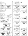
次に、上記のように構成した実施形態の動作を説明する。まず、頭部検出ECU10の動作について説明すると、同ECU10は、所定時間ごとに、図2の頭部検出プログラムをステップS100にて開始し、ステップS102以降の処理を実行する。ステップS102においては、カメラ11に撮影指示を出力するとともに、カメラによる撮影画像を入力する。そして、ステップS104にて、前記入力した撮影画像から乗員頭部を認識する。具体的には、撮影画像から人間の頭部を表す画像を画像認識によって抽出する。なお、このステップS104の処理においては、カメラ11ごとに行ってもよいし、複数のカメラ11から入力した撮影画像を合成した後に、乗員頭部を認識してもよい。
【0044】
次に、ステップS106にて乗員頭部が存在するか否かを判定、すなわちステップS104の処理によって乗員頭部が認識されたか否かを判定する。乗員頭部が存在すれば、ステップS106にて「Yes」と判定し、ステップS110にて入力した撮影画像から前記認識した頭部の位置を計算する。そして、ステップS110にて、この計算した頭部の位置およびエアバックの取付け位置を用いて頭部からエアバックまでの距離Xを計算する。この距離Xの計算後、ステップS112にて、頭部が存在することを表す頭部存在データ、頭部の位置を表す位置データ、および頭部からエアバックまでの距離Xを表す距離データからなる頭部情報をバス100上に出力する。これらのステップS108〜S112の処理においては、ステップS104にて複数の頭部が認識されている場合には、複数の頭部のそれぞれに対して前記処理が実行される。
【0045】
一方、頭部が存在しないとき、ステップS106にて「No」と判定し、ステップS114にて、頭部が存在しないことを表す頭部不存在データを頭部情報としてバス100上に出力する。これらのステップS112,S114の処理によって出力された頭部情報は同情報を必要とするECU内のインターフェース回路内に取込まれ、新たな頭部情報を取込むまで保存される。
【0046】
前記ステップS112,S114の処理後、ステップS116にて、前記ステップS102の処理により入力した撮影画像から複数のシートおよびシートバックをそれぞれ認識する。そして、ステップS118にて各シートバックの角度を計算し、ステップS120にて各シートの前後位置を計算する。これらの計算処理後、ステップS122にて、前記計算した角度を表す角度データおよび前記計算した前後位置を表す前後位置データをシート情報として、バス100上に出力する。この出力されたシート情報も、同情報を必要とするECU内のインターフェース回路内に取込まれ、新たなシート情報を取込むまで保存される。
【0047】
次に、ステップS124にて、前記ステップS102の処理により入力した撮影画像からシート上の物体の認識処理により、シート上の物体(例えば、荷物)の有無を検出して、同有無を表す物体存在データをバス100上に出力する。この出力された物体存在データも、同データを必要とするECU内のインターフェース回路内に取込まれ、新たな物体存在データを取込むまで保存される。そして、ステップS126にて、この頭部検出プログラムの実行を終了する。
【0048】
次に、体格検出ECU20の動作について説明すると、同ECU20は、所定時間ごとに、図3の体格検出プログラムをステップS200にて開始し、ステップS202以降の処理を実行する。ステップS202においては、前記頭部検出ECU10によって出力されてインターフェース回路に記憶されている頭部情報を入力する。詳しくは、体格検出ECU20のCPUが、頭部情報を、体格検出ECU20内のインターフェース回路から入力する。以下、この種のインターフェース回路に取込まれている各種情報に関しても同じである。
【0049】
次に、ステップS204にて前記入力した頭部情報に基づいて乗員頭部の存在を判定する。頭部が存在していれば、ステップS204にて「Yes」と判定し、ステップS206にて入力した頭部情報の位置データによって表された頭部の位置に基づいて乗員の姿勢をシートごとに認識する。例えば、乗員が正常にシートに着座にしているか、乗員がドア側にもたれているか、体の一部をインストルメントパネルに載せているかなどを認識する。そして、ステップS208にて、前記認識した乗員の姿勢に基づいて、体格判別が可能であるかをシートごとに判定する。すなわち、乗員がドア側にもたれているか、体の一部をインストルメントパネルに載せていて、シート以外の部位で乗員の体重を支えているような姿勢を乗員がとっている場合には、後述する荷重センサ21により乗員の体格が正確に検出されないからである。
【0050】
乗員が正常にシート上に着座していて体格判別可能であれば、ステップS208にて「Yes」と判定し、ステップS210にシートごとに荷重センサ21から検出荷重を入力する。この入力された荷重は、ステップS212の処理により、荷重センサ21の零点補正値を用いて補正されて体格データとされる。そして、ステップS214にて体格データに基づいて体格判別して、体格判別データを生成する。この体格判別は、乗員を複数の体格ランクに区分けするもので、体格ランクとしては、例えば通常の大人、小柄な大人、子供などが採用されている。この場合、体格データよって表された荷重(すなわち、体重)の大きさにおける複数種類の範囲が前記体格ランクに割当てられている。
【0051】
前記ステップS214の処理後、ステップS216にて、前記生成された体格判別データを体格情報として、バス100上に出力する。この出力された体格情報も、同情報を必要とするECU内のインターフェース回路内に取込まれ、新たなシート情報を取込むまで保存される。そして、ステップS230にて、この体格検出プログラムの実行を終了する。
【0052】
一方、体格判別が不能なシートに関する場合には、ステップS208にて「No」と判定して、ステップS230にてこの体格検出プログラムの実行を終了する。このようなステップS206〜S216の処理により、体格判別が可能な場合にのみ、体格データおよび体格判別データは検出荷重を用いて更新される。言い換えれば、乗員の頭部が検出されても、すなわち乗員がシートに着座していても、乗員がドア側にもたれ、また体の一部をインストルメントパネルに載せるなど、シート以外の部位で乗員の体重を支えているような姿勢を乗員がとっている場合には、体格データおよび体格判別データは更新されない。これにより、乗員の着座姿勢にかかわらず、体格データおよび体格判別データは常に適切に保たれる。
【0053】
また、頭部が存在しないシート、すなわち乗員が着座していないシートに関しては、ステップS204にて「No」と判定してステップS218以降の処理を実行する。ステップS218においては、体格データおよび体格判別データをクリアする。そして、ステップS220にて物体存在データを入力し、ステップS222にて物体存在データに基づいてシート上の物体の存在の有無をシートごとに判定する。シート上に乗員以外の物体(例えば、荷物)が存在していれば、ステップS222にて「Yes」と判定して、前記ステップS216の処理後、ステップS230にてこの体格検出プログラムの実行を終了する。
【0054】
一方、シート上に乗員以外の物体(例えば、荷物)も存在していなければ、ステップS222にて「No」と判定して、ステップS224〜S228の処理を実行する。ステップS224においては、シートごとに、荷重センサ21からオフセット値(荷重センサ出力)を入力して、同オフセット値を零点補正値とする。ステップS226においてはシート情報(角度データおよび前後位置データ)を入力し、ステップS228にて前記零点補正値をシート情報で補正する。すなわち、零点補正値を、シートバックの角度およびシートの前後位置を用いて補正する。そして、このシート情報で補正された零点補正値が、前記ステップS212の入力荷重の補正処理に利用される。
【0055】
このようなステップS212,S220〜S228による零点補正に関する処理により、荷重センサ21が回路上のオフセット値、経年変化によるオフセット値などを有していても、荷重センサ21のオフセット値による影響が零点補正によってなくなるので、検出される乗員の体格の検出精度が常に良好になる。また、この零点補正値は、シートバックの角度およびシートの前後位置によって補正されるので、零点補正値(オフセット値)がシートバックの角度およびシートの前後位置による影響を受けなくなり、検出される乗員の体格の検出精度がより良好になる。
【0056】
なお、図4に示すように、上記図3の体格検出プログラムを、それらのステップS212,S214の処理の間にステップS240,S242の処理を付加するように変形してもよい。ステップS240の処理は、前記ステップS226の処理と同様なシート情報を入力する処理である。ステップS242の処理は、前記ステップS212で零点補正した体格データを、シート情報で補正する。これによれば、乗員が着座している状態でも、体格データ(すなわち、検出荷重)がシートバックの角度およびシートの前後位置による影響を受けなくなり、計算される体格データがより正確に乗員の体格を表すようになる。
【0057】
次に、これらの頭部情報および体格情報に基づく各種車両デバイスの制御について説明する。まず、エアバック装置31の制御について説明すると、エアバックECU30は、図5のステップS300にてエアバック制御プログラムの実行を開始する。そして、ステップS302にて頭部情報(特に、頭部存在データおよび距離データ)を入力して、ステップS304にてシートごとに乗員頭部が存在するかを判定する。
【0058】
乗員頭部が存在しているシートに関しては、ステップS304にて「Yes」と判定し、ステップS306以降の処理を実行する。ステップS306においては、体格情報(体格判別データ)を入力する。そして、ステップS308にて、展開圧力テーブルを参照して、体格判別データおよび距離データに対応した展開圧力の上限値を設定する。展開圧力テーブルは、エアバックECU30内に予め用意されているもので、図6に示すように、体格データ(通常の大人、小柄な大人および子供)と、乗員頭部からエアバックまでの距離Xとに対応させて、エアバックの展開圧力の上限値および展開禁止指示を記憶している。図6中の値X1,X2,X3はこの順に大きくなる値であり、このテーブルからも解るように、乗員頭部からエアバックまでの距離Xが大きくなるに従って展開圧力の上限値が大きな値に設定されるとともに、子供から通常の大人になるに従って同上限値が大きな値に設定される。
【0059】
前記ステップS308の処理後、ステップS310にて車両の衝突を判定する。この衝突判定は、衝突検出用センサ群32から検出信号、特に車体に配置した加速度センサの検出値に基づいて行われる。車両の衝突が判定されなければ、ステップS310にて「No」と判定して、ステップS318にてエアバック制御プログラムの実行を終了する。
【0060】
一方、車両の衝突が判定されると、ステップS310にて「Yes」と判定し、ステップS312にてエアバックの展開圧力を決定する。この展開圧力の決定においては、前記加速度センサによって検出された加速度が大きくなるに従って、すなわち衝突の程度が大きくなるに従って、展開圧力が大きな値に設定される。また、この決定される展開圧力は、前記ステップS308の処理によって制限された上限値以下の値に制限される。
【0061】
次に、ステップS314にてエアバック装置31を制御して、前記決定された展開圧力に応じた態様でエアバックの展開が制御される。具体的には、エアバックECU30は、エアバック装置31において点火されるインフレータの数を制御して爆発する火薬量を変化させ、また各インフレータの点火タイミングをずらすことにより、エアバックの展開圧力を前記決定圧力に制御する。
【0062】
このようなステップS302〜S314の処理により、車両の衝突検出時に展開されるエアバックの展開態様が、通常の大人、小柄な大人、子供などのように乗員の体格に応じて制御されるので、乗員を適切に保護できる。また、エアバックの展開態様が、乗員頭部からエアバックまでの距離Xに応じても制御されて、エアバックが車両衝突時の状況に応じて的確に展開するようになり、乗員をより適切に保護できる。
【0063】
一方、ステップS304にて「No」すなわち乗員頭部が不存在であると判定されたシートに関しては、ステップS316の処理によりエアバックの展開が禁止される。これにより、乗員がシートに着座していない場合には、不必要なエアバックの展開を避けることができ、エアバックの展開による修理費を低減できるとともに、無駄な電力消費を抑えることができる。
【0064】
次に、シートベルト装置41の制御について説明すると、シートベルトECU40は、図7のステップS400にてシートベルト制御プログラムの実行を開始する。そして、ステップS402にて頭部情報(特に、頭部存在データ)を入力して、ステップS404にてシートごとに乗員頭部が存在するかを判定する。
【0065】
乗員頭部が存在しているシートに関しては、ステップS404にて「Yes」と判定し、ステップS406以降の処理を実行する。ステップS406においては、体格情報(体格判別データ)を入力する。そして、ステップS408にて、張力テーブルを参照して、体格判別データに対応したシートベルトの張力を設定する。張力テーブルは、シートベルトECU40内に予め用意されているもので、図8に示すように、体格データ(通常の大人、小柄な大人および子供)に対応させて、シートベルトの車両衝突時の張力を記憶している。このテーブルからも解るように、子供から通常の大人になるに従ってシートベルトの張力は大きな値に設定される。
【0066】
前記ステップS408の処理後、ステップS410にて、衝突検出用センサ群32からの検出信号に基づいて車両の衝突を判定する。この衝突判定は、実際に車両が他の物体に衝突したことを含むとともに、車両の前方物体に対する衝突予測をも含む。具体的には、赤外線などを用いたレーダ、車速センサ、クラッシュボックス、加速度センサなどからの検出信号をそれぞれ入力して、これらの検出信号を用いて衝突が予測または検出される。車両の衝突が予測または判定されなければ、ステップS410にて「No」と判定して、ステップS418にてシートベルト制御プログラムの実行を終了する。
【0067】
一方、車両の衝突が予測または判定されると、ステップS410にて「Yes」と判定し、ステップS412にてシートベルト装置41を制御して、シートベルトモータおよびプリテンショナーを作動させる。具体的には、車両の衝突が予測された場合に、シートベルトモータの作動が制御される。このシートベルトモータの作動制御においては、シートベルトモータに流す電流量を、前記ステップS408の処理により乗員の体格に応じて設定された張力に加え、衝突予測における衝突可能性の程度に応じて制御することにより、シートベルトの巻取り張力を制御する。また、車両の衝突が検出された場合に、シートベルトプリテンショナーの作動が制御される。この場合には、前記ステップS408の処理によって乗員の体格に応じて設定された張力に加え、衝突検出における衝突の大きさの程度に応じて、プリテンショナーにおいて点火されるインフレータの数を制御して爆発する火薬量を変化させ、また各インフレータの点火タイミングをずらすことにより、シートベルトの巻取り張力を制御する。
【0068】
このようなステップS402〜S412の処理により、車両衝突の予測および検出時に巻取られるシートベルトの張力が、通常の大人、小柄な大人、子供などのように乗員の体格に応じて制御されるので、乗員を適切に保護できる。
【0069】
一方、ステップS404にて「No」すなわち乗員頭部が不存在であると判定されたシートに関しては、ステップS414の処理によりプリテンショナーの作動が禁止されるとともに、ステップS416の処理によりシートベルトモータの作動が禁止される。これにより、不必要なシートベルトの巻取りを避けることができ、プリテンショナーの作動による修理費を低減できるとともに、無駄な電力消費を抑えることができる。
【0070】
なお、本実施形態では、車両衝突の予測または検出時に乗員を拘束する手段として、エアバックおよびシートベルトの例にしたが、他の乗員拘束装置が車両に搭載されている場合には、前記図5のステップS304,S316および図7のS404,S414,S416の処理と同様に、乗員頭部がシート上に存在しないときには、前記他の乗員拘束装置の作動を禁止するとよい。
【0071】
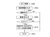
次に、ミラー装置51の制御について説明すると、ミラーECU50は、図9のステップS500にてミラー制御プログラムの実行を開始する。そして、ステップS502にて頭部情報(特に、頭部存在データおよび位置データ)を入力して、ステップS504にて運転席シート上に乗員頭部が存在するかを判定する。
【0072】
運転席シート上に乗員頭部が存在していなければ、ステップS504にて「No」と判定し、ステップS512にてこのミラー制御プログラムの実行を終了する。一方、運転席シート上に乗員頭部が存在していれば、ステップS504にて「Yes」と判定して、ステップS506以降の処理を実行する。ステップS506においては、車速センサ52から車速Vを入力する。そして、ステップS508にて、車速Vが所定の小さな前進車速V1以上であるかを判定する。なお、この前進車速V1とは、車両の後退を除外して、車両が前進しているときの車速を意味するとともに、車両が停止していなくて走行中であることを判定できる程度に小さな値である。これにより、車両の前進が判定される。
【0073】
車速Vが前進車速V1以上すなわち車両が前進していれば、ステップS508にて「Yes」と判定して、ステップS510にて室内ミラーおよびドアミラーの角度を調整して、ステップS512にてミラー制御プログラムの実行を終了する。このミラーの角度調整においては、前記ステップS502の処理によって入力した頭部情報中の運転者頭部の位置を表す位置データを用いてミラー装置51を制御して、室内ミラーおよびドアミラーの角度を運転者が見易い角度に調整する。また、車速Vが前進車速V1以上でなければ、ステップS508にて「No」と判定して、ステップS512にてこのミラー制御プログラムの実行を終了する。
【0074】
これによれば、運転者が手動操作で室内ミラーおよびドアミラーの角度を調整する手間を省くことができるようになる。また、車両の前進を検出することにより、不必要なミラーの作動を抑えることができ、消費電力を節約できる。なお、車速Vが前進車速V1以上であることを条件とする代わりに、運転者による指示を条件に、ステップS510の処理を実行して、室内ミラーおよびドアミラーの角度を運転者の頭部位置に応じて自動調整するようにしてもよい。また、室内ミラーおよびドアミラー以外にも、後方確認用ミラーが存在する場合には、同ミラーも前記と同様に制御するとよい。
【0075】
次に、ヘッドレスト装置61の制御について説明すると、ヘッドレストECU60は、図10のステップS600にてヘッドレスト制御プログラムの実行を開始する。そして、ステップS602にて頭部情報(特に、頭部存在データおよび位置データ)を入力して、ステップS604にてシートごとに乗員頭部が存在するかを判定する。
【0076】
全てのシートに乗員頭部が存在していなければ、ステップS604にて「No」と判定し、ステップS608にてこのヘッドレスト制御プログラムの実行を終了する。一方、乗員頭部が存在しているシートに関しては、ステップS604にて「Yes」と判定して、ステップS606のヘッドレストの高さ調整処理を実行して、ステップS608にてこのヘッドレスト制御プログラムの実行を終了する。このヘッドレストの高さ調整処理においては、前記ステップS602の処理によって入力した頭部情報中の運転者頭部の位置を表す位置データを用いてヘッドレスト装置61を制御して、ヘッドレストの高さを乗員に適した高さまで移動する。
【0077】
これによれば、運転者が手動操作でヘッドレストの高さを調整する手間を省くことができるようになる。なお、この場合も、乗員による指示を条件に、ステップS606の処理を実行して、ヘッドレストを乗員に適した高さに自動調整するようにしてもよい。
【0078】
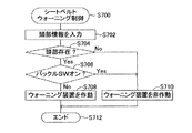
次に、シートベルトウォーニング装置71の制御について説明すると、シートベルトウォーニングECU70は、図11のステップS700にてシートベルトウォーニング制御プログラムの実行を開始する。そして、ステップS702にて頭部情報(特に、頭部存在データ)を入力して、ステップS704にてシートごとに乗員頭部が存在するかを判定する。
【0079】
乗員頭部が存在しているシートに関しては、ステップS704にて「Yes」と判定し、ステップS706以降の処理を実行する。ステップS706においては、バックルスイッチ72がオンであるかを判定することにより、シートベルトの装着の有無を判定する。そして、バックルスイッチ72がオンしていなければ、ステップS706にて「No」と判定して、ステップS708にてシートベルトウォーニング装置71を制御して、ウォーニングランプを点灯したり、ウォーニングブザーを作動させて、ステップS708にてこのシートベルトウォーニング制御プログラムの実行を終了する。
【0080】
一方、乗員頭部が存在しないシートに関しては、ステップS704にて「No」と判定して、ステップS712にてこのシートベルトウォーニング制御プログラムの実行を終了する。また、乗員頭部が存在してもバックルスイッチ72がオンであるシートに関しては、ステップS704,S706にて共に「Yes」と判定して、ステップS712にてこのシートベルトウォーニング制御プログラムの実行を終了する。
【0081】
これによれば、シートに物が置かれている場合は除外され、シートに乗員が着座し、かつ乗員がシートベルトを装着していないときのみ、シートベルトの装着が乗員に警告されるので、不必要な警告が回避される。
【0082】
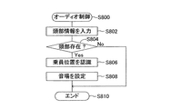
次に、オーディオ装置81の制御について説明すると、オーディオECU80は、図12のステップS800にてオーディオ制御プログラムの実行を開始する。そして、ステップS802にて頭部情報(特に、頭部存在データ)を入力して、ステップS804にてシートごとに乗員頭部が存在するかを判定する。
【0083】
全てのシートに乗員頭部が存在していなければ、ステップS804にて「No」と判定し、ステップS810にてこのオーディオ制御プログラムの実行を終了する。一方、乗員頭部が存在しているシートがあれば、ステップS804にて「Yes」と判定して、ステップS806,S808の処理を実行する。ステップS806においては、乗員位置すなわち乗員が着座しているシートを認識する。ステップS808においては、前記認識結果を用いてオーディオ装置81を制御して、オーディオ装置81による音場を設定する。この場合、運転席、助手席、後部右席および後部左席のうちで乗員が着座しているシートの組み合わせに応じて、同組み合わせに適したオーディオ装置81による音場が設定される。
【0084】
これによれば、乗員の手動操作による音場設定の手間を省くことができるようになる。なお、この場合も、乗員による指示を条件に、このオーディオ制御プログラムを実行して、乗員の位置に適したオーディオ装置81による音場を自動調整するようにしてもよい。
【0085】
次に、情報表示装置91の制御について説明すると、情報表示ECU90は、図13のステップS900にて情報表示制御プログラムの実行を開始する。そして、ステップS902にて3D表示モードであるかを判定するとともに、ステップS904にて重畳表示モードであるかを判定する。これらのモードは運転者により設定されるもので、図示しない操作子によって選択される。3D表示モードおよび重畳表示モードのいずれのモードも選択されていなければ、ステップS934にてこの情報表示制御プログラムの実行を終了する。重畳表示モードが選択されていれば、ステップS906〜S918の処理を実行する。3D表示モードが選択されていれば、ステップS920〜S932の処理を実行する。
【0086】
重畳表示モードが選択されている場合について説明すると、ステップS906にて頭部情報(特に、頭部存在データおよび位置データ)を入力して、ステップS908にて運転席シート上に乗員頭部が存在するかを判定する。運転席シート上に乗員頭部が存在していなければ、ステップS908にて「No」と判定し、ステップS934にてこの情報表示制御プログラムの実行を終了する。一方、運転席シート上に乗員頭部が存在していれば、ステップS908にて「Yes」と判定して、ステップS910にて車室外カメラ93に対して撮影を指示し、同カメラ93にて撮影した画像を入力する。
【0087】
次に、ステップS912にて、前記入力した画像から表示すべき表示物を抽出する。この表示物は、道路および道路近辺の要注意物体(例えば、道路上の回避物、道路標識)である。前記ステップS912の処理後、ステップS914にて、その他の重畳すべき表示物に関する画像を生成する。この場合、例えば、ナビゲーション装置92から得た誘導経路を指示するためのマークなどである。
【0088】
次に、ステップS916にて、前記ステップS906の処理によって入力した頭部情報中の位置データによって表される運転者頭部の位置を用いて、前記抽出した表示物および生成した表示物画像の実路面上の表示位置を決定する。そして、ステップS918にて、図14に示すように、実路面上の前記決定した表示位置に、抽出した要注意物体91bをフロントガラス上でマーキングしたり、抽出した要注意物体に関する情報91c、およびその他の表示物(例えば、誘導路指示マーク)91aをフロントガラスに表示する。
【0089】
一方、3D表示が選択されている場合に実行されるステップS920〜S930においても、前記ステップS906〜S916の処理と同様にして、車室外カメラ93で撮影した画像から表示すべき表示物を抽出するとともに、その他の3D表示すべき表示物に関する画像を生成し、またそれらの表示位置も決定する。この場合、その他の表示物は、例えば、車両に関する操作スイッチである。そして、ステップS932にて、前記ステップS920の処理によって入力した頭部情報中の位置データによって表される運転者頭部の位置を用いて、前記抽出した表示物および生成した表示物画像の虚像91d,91eを3D表示する。
【0090】
そして、運転者が前記操作スイッチの虚像91dを操作した場合には、その操作は指先検知カメラ94によって検出される。そして、図示しないプログラムの実行により、この操作スイッチの虚像91dの操作の検出結果は、同操作スイッチに関連した制御装置に送信されて利用される。
【0091】
このように、この情報表示制御プログラムの実行により、運転者頭部の位置に従って表示物が実路面に重畳表示されたり、表示物が3D表示されるので、運転者にとって便利になる。
【0092】
また、この情報表示制御プログラムにあっては、運転者に対する重畳表示および3D表示を行うようにしたが、他の乗員に対しても重畳表示および3D表示を行うようにしてもよい。この場合、ステップS906,S920の処理によって入力した頭部情報のうちから前記他の乗員に関する頭部情報を抽出して、前記と同様の処理を行うようにすればよい。
【0093】
以上、本発明の一実施形態について説明したが、本発明の実施にあたっては、上記実施形態に限定されるものではなく、本発明の目的を逸脱しない限りにおいて種々の変更が可能である。
【0094】
例えば、上記実施形態においては、乗員の体格を荷重センサ21によって検出された荷重に基づいて検出するようにした。しかし、この荷重センサ21によって検出された荷重に代えまたは加えて、図1に破線で示すシートベルトテンションセンサ22によって検出されたシートベルトの張力と、シートベルトウォーニングECU70に接続されたバックルスイッチ72の検出信号とを用いて、乗員の体格を検出するようにしてもよい。さらに、シートベルトの引出し量を検出するセンサを設けて、シートベルトの引出し量に応じて乗員の体格を判別するようにしてもよい。
【0095】
また、上記実施形態においては、乗員頭部の位置を表す位置データを直接的または間接的に利用する車両デバイスとして、エアバック装置31、シートベルト装置41、ミラー装置51、ヘッドレスト装置61、オーディオ装置81および情報表示装置91を例にして説明したが、この位置データは他の車両デバイス、例えばエアーコンディショナー装置にも適用できる。エアーコンディショナー装置の場合、乗員頭部の位置に基づいて風の向きを制御するようにするとよい。
【0096】
また、上記実施形態においては、乗員の頭部検出、乗員の体格検出および各種車両デバイスの制御のために独立したECUを用いるようにしたが、ECUの処理速度などを考慮して、これらのECUは適宜統合してもよい。例えば、乗員の頭部および体格検出を1つのECUで実行するようにしてもよい。また、上記実施形態の車両デバイスのうちの複数の車両デバイスを適宜組み合わせて、1つのECUで制御するようにしてもよい。
【図面の簡単な説明】
【図1】本発明の一実施形態に係る車両デバイス制御装置の全体ブロック図である。
【図2】図1の頭部検出ECUにより実行される頭部検出プログラムを示すフローチャートである。
【図3】図1の体格検出ECUにより実行される体格検出プログラムを示すフローチャートである。
【図4】前記体格検出プログラムの一部を変更した体格検出プログラムの変更部分を示すフローチャートである。
【図5】図1のエアバックECUにより実行されるエアバック制御プログラムを示すフローチャートである。
【図6】展開圧力テーブルの内容を示す図である。
【図7】図1のシートベルトECUにより実行されるシートベルト制御プログラムを示すフローチャートである。
【図8】張力テーブルの内容を示す図である。
【図9】図1のミラーECUにより実行されるミラー制御プログラムを示すフローチャートである。
【図10】図1のヘッドレストECUにより実行されるヘッドレスト制御プログラムを示すフローチャートである。
【図11】図1のシートベルトウォーニングECUにより実行されるシートベルトウォーニング制御プログラムを示すフローチャートである。
【図12】図1のオーディオECUにより実行されるオーディオ制御プログラムを示すフローチャートである。
【図13】図1の情報表示ECUにより実行される情報表示制御プログラムを示すフローチャートである。
【図14】重畳表示例を示す図である。
【図15】3D表示例を示す図である。
【符号の説明】
10…頭部検出ECU、11…カメラ、20…体格検出ECU、21…荷重センサ、30…エアバックECU、31…エアバック装置、40…シートベルトECU、41…シートベルト装置、50…ミラーECU、51…ミラー装置、60…ヘッドレストECU、61…ヘッドレスト装置、70…シートベルトウォーニングECU、71…シートベルトウォーニング装置、80…オーディオECU、81…オーディオ装置、90…情報表示ECU、91…情報表示装置。[0001]
TECHNICAL FIELD OF THE INVENTION
The present invention relates to a vehicle device control device that captures an image of a vehicle interior with a camera, detects information about an occupant's head based on a captured image, and controls a vehicle device according to a detection result of the head.
[0002]
[Prior art]
Conventionally, based on an image of the passenger compartment taken by a camera, the presence or absence of an occupant, the position of the occupant's head to detect the occupant's sitting posture, the distance between the occupant and the instrument panel, etc. It is known that the presence or absence of the operation of the airbag is controlled in accordance with the detection results (see Patent Document 1).
[0003]
[Patent Document 1]
JP 2001-331790 A
[0004]
[Problems to be solved by the invention]
However, it is not sufficient to control a vehicle device including an airbag device based only on information indicating the position of the occupant's head as in the above-described conventional example. That is, the occupant sitting on the seat may be a normal adult, a small adult, or a child. In this case, in order to protect the occupant, it is preferable to change the deployment mode of the airbag according to the occupant. However, with the above-described conventional device, the deployment mode of the airbag cannot be changed according to the occupant. Device control is not always appropriate.
[0005]
Summary of the Invention
The present invention has been made to address the above problems, and has as its object to provide a vehicle including an airbag device, such as a seatbelt device, a mirror device, an information display device, a headrest device, a seatbelt warning device, and an audio device. A vehicle device control device that appropriately controls a device is provided.
[0006]
In order to achieve the above object, the features of the present invention include a camera that captures an image of a vehicle interior, a head detection unit that detects information about an occupant's head from the captured image, and a physique of the occupant. It is provided with a physique detecting means and a device control means for controlling a vehicle device according to the detected occupant head information and the physique. In this case, the vehicle device is, for example, a seat belt device including a seat belt winding device, an airbag device, or the like.
[0007]
According to this, the device control means controls the vehicle device according to the information on the occupant head and the physique of the occupant, so that the vehicle device is appropriately controlled.
[0008]
Further, in the present invention, the head detection means includes head existence detection means for detecting the presence or absence of an occupant head as head information, and the vehicle device is a restraint device for restraining an occupant at the time of a vehicle collision. The control means inhibits the operation of the restraint device when the absence of the occupant head is detected by the head presence detection means, and inhibits the operation of the restraint device when the presence of the occupant head is detected by the head presence detection means. And the operation of the restraint device may be controlled in accordance with the detected physique. Also in this case, the restraint device is, for example, a seat belt device including a seat belt winding device, an airbag device, or the like.
[0009]
According to this, unnecessary operation of the restraint device can be avoided, repair costs after the operation can be reduced, and wasteful power consumption can be suppressed. Further, the restraint device is appropriately controlled according to the physique of the occupant.
[0010]
In the present invention, the vehicle device may be a seat belt retractor, and the device control means may control the tension of the seat belt when the seat belt retractor operates according to the detected physique.
[0011]
According to this, the seat belt retractor that operates at the time of vehicle collision prediction, collision, etc. applies different tension to the seat belt according to the occupant's physique like a normal adult, a small adult, a child, etc. I do. Therefore, the occupant can be restrained by the seat belt having an appropriate tension, and the occupant can be appropriately protected.
[0012]
Further, in the present invention, the vehicle device may be an airbag device, and the device control means may control a deployment mode of the airbag when the airbag device is operated according to the detected physique of the occupant.
[0013]
According to this, the deployment mode of the airbag deployed at the time of predicting the collision of the vehicle is controlled according to the physique of the occupant, such as a normal adult, a small adult, and a child. Therefore, the occupant can be properly protected.
[0014]
Further, in the present invention, the head detecting means further includes head distance detecting means for detecting a distance from an occupant's head to the airbag as head information, and the device control means determines a deployment mode of the airbag. The control may be performed according to the detected distance in addition to the occupant's physique.
[0015]
According to this, the deployment mode of the airbag is also controlled according to the distance from the occupant head to the airbag, and the airbag is deployed properly according to the situation at the time of the vehicle collision, and Can be better protected.
[0016]
Further, according to the present invention, the head device further includes a wearing detection unit that detects wearing of a seat belt, and a warning device that is provided independently of the vehicle device and warns an occupant of wearing of the seat belt. The part detection means includes head presence detection means for detecting the presence or absence of the occupant head as head information, and the device control means further detects that the occupant head is present by the head presence detection means, Further, when the wearing of the seat belt is not detected by the wearing detecting means, the warning device may be operated.
[0017]
According to this, the case where an object is placed on the seat is excluded, and only when the occupant is seated on the seat and the occupant does not wear the seat belt, the occupant is warned of wearing the seat belt, Unnecessary warnings are avoided.
[0018]
Further, in the present invention, further provided is another vehicle device that is provided independently of the vehicle device and requires a position change depending on the position of the occupant head. The vehicle control apparatus may further include a head position detecting unit that detects a position as head information, and the device control unit may further control the other vehicle device according to the detected position of the occupant head. In this case, other vehicle devices include, for example, a mirror device having a rear-viewing mirror, an information display device that displays various types of information for the occupant, a headrest device that can adjust the height of the headrest, and a wind direction that can be changed. Examples include an air conditioner device and an audio device capable of changing a sound field.
[0019]
According to this, even if the occupant does not manually operate a vehicle device that requires a position change according to the position of the occupant head, the position of the vehicle device is automatically changed, which is convenient for the occupant.
[0020]
Further, in this case, the other vehicle device is a mirror for confirming the rear of the vehicle, and further includes forward detection means for detecting the forward movement of the vehicle. Is detected, the position of the mirror may be controlled in accordance with the detected position of the occupant head.
[0021]
According to this, unnecessary operation of the mirror can be suppressed, and power consumption can be saved.
[0022]
Further, in the present invention, the head detecting means includes a head position detecting means for detecting the position of the occupant's head as head information, and the physique detecting means detects the load applied to the seat as the occupant's physique. A sensor, determining means for determining whether the detected load indicates the physique of the occupant based on the detected position of the occupant head, and determining that the detected load indicates the physique of the occupant When the determination is made by the means, the physique data representing the physique of the occupant is updated to the detected load, and when the detected load is not determined by the determination means to represent the physique of the occupant, the physique data is updated. It is preferable to include a physique data updating unit that maintains the previous value without updating.
[0023]
If the occupant is leaning against the door or placing a part of his body on the instrument panel and supporting the occupant's weight at a location other than the seat, the load sensor will Physique is not accurately detected. However, according to the configuration, only when it is determined that the load detected by the load sensor represents the physique of the occupant, the physique data is updated to the output load, and at other times, the physique data is updated to the previous value. This physique data is maintained and used for controlling the vehicle device. Therefore, the vehicle device is always appropriately controlled regardless of the sitting posture of the occupant.
[0024]
In the present invention, the physique detecting means may include a load sensor for detecting a load applied to the seat as a physique of the occupant, and an object absence detecting for detecting that no object is present on the seat based on the photographed image. Detecting means, zero point correction value setting means for setting a zero point correction value based on the detection output of the load sensor when the absence of an object on the sheet is detected by the object absence detecting means, And a zero-point correcting unit that corrects the applied load to a zero point using the detected zero-point correction value.
[0025]
A load sensor may have an offset value on a circuit and an offset value due to aging. However, according to the above configuration, the influence of such an offset value of the load sensor is eliminated by the zero point correction, so that the detection accuracy of the detected physique of the occupant is always improved.
[0026]
Further, the zero point correction value setting means includes sheet state detection means for detecting at least one of the angle of the seat back and the front / rear position of the seat based on an image taken by the camera, and the zero point correction value is detected. The correction may be made using at least one of the angle of the seat back and the front / rear position of the seat.
[0027]
The detection output output from the load sensor is affected by the angle of the seat back and the front / rear position of the seat. However, according to the above configuration, the influence of the angle of the seat back and the front / rear position of the seat is eliminated, so that the detection accuracy of the detected physique of the occupant is further improved.
[0028]
In the present invention, the physique detecting means may include a load sensor that detects a load applied to the seat as a physique of the occupant, and at least one of an angle of a seat back and a front-back position of the seat based on the photographed image. And a correcting means for correcting the load detected by the load sensor by at least one of the detected angle of the seat back and the front / rear position of the seat.
[0029]
As described above, the detection output output from the load sensor is affected by the angle of the seat back and the front / rear position of the seat. However, according to the above configuration, the influence of the angle of the seat back and the front / rear position of the seat is eliminated, so that the detection accuracy of the detected physique of the occupant is always improved.
[0030]
BEST MODE FOR CARRYING OUT THE INVENTION
Hereinafter, an embodiment of the present invention will be described with reference to the drawings. FIG. 1 is an overall block diagram of a vehicle device control device according to the embodiment.
[0031]
The vehicle device control device is connected to a
[0032]
The
[0033]
The
[0034]
The
[0035]
The
[0036]
A collision
[0037]
The
[0038]
The
[0039]
The seat
[0040]
The
[0041]
The
[0042]
Further, the
[0043]
Next, the operation of the embodiment configured as described above will be described. First, the operation of the
[0044]
Next, it is determined in step S106 whether or not the occupant's head is present, that is, whether or not the occupant's head is recognized in the process in step S104. If the head of the occupant is present, “Yes” is determined in step S106, and the position of the recognized head is calculated from the captured image input in step S110. Then, in step S110, the distance X from the head to the airbag is calculated using the calculated head position and airbag attachment position. After the calculation of the distance X, in step S112, the data includes head presence data representing the presence of the head, position data representing the position of the head, and distance data representing the distance X from the head to the airbag. The head information is output on the
[0045]
On the other hand, when the head does not exist, “No” is determined in step S106, and in step S114, the head absence data indicating that the head does not exist is output to the
[0046]
After the processes in steps S112 and S114, in step S116, a plurality of seats and seatbacks are respectively recognized from the captured image input in the process in step S102. Then, the angle of each seat back is calculated in step S118, and the front / rear position of each seat is calculated in step S120. After these calculation processes, in step S122, the angle data indicating the calculated angle and the front-rear position data indicating the calculated front-rear position are output to the
[0047]
Next, in step S124, the presence / absence of an object (for example, luggage) on the sheet is detected by object recognition processing on the sheet from the captured image input in step S102, and the presence / absence of the object is represented. The data is output on the
[0048]
Next, the operation of the
[0049]
Next, in step S204, the presence of the occupant head is determined based on the input head information. If the head exists, it is determined as “Yes” in step S204, and the posture of the occupant is set for each seat based on the position of the head represented by the position data of the head information input in step S206. recognize. For example, it recognizes whether the occupant is properly seated on the seat, whether the occupant is leaning on the door side, whether a part of the body is placed on the instrument panel, and the like. Then, in step S208, it is determined whether the physique can be determined for each seat based on the recognized occupant's posture. That is, if the occupant is leaning on the door side or a part of the body is resting on the instrument panel and the occupant is taking a posture that supports the occupant's weight at a part other than the seat, This is because the occupant's physique is not accurately detected by the
[0050]
If the occupant is normally seated on the seat and the physique can be determined, “Yes” is determined in step S208, and the detected load is input from the
[0051]
After the processing in step S214, in step S216, the generated physique determination data is output to the
[0052]
On the other hand, in the case of a sheet whose physique cannot be determined, “No” is determined in step S208, and the execution of the physique detection program ends in step S230. Through the processing in steps S206 to S216, the physique data and the physique determination data are updated using the detected load only when the physique determination is possible. In other words, even if the head of the occupant is detected, that is, even if the occupant is seated on the seat, the occupant leans on the door side, and a part of the body is placed on the instrument panel. When the occupant is in a posture supporting the weight of the physique, the physique data and the physique discrimination data are not updated. Thereby, regardless of the sitting posture of the occupant, the physique data and the physique discrimination data are always appropriately maintained.
[0053]
In addition, regarding a seat having no head, that is, a seat where the occupant is not seated, “No” is determined in the step S204, and the processes from the step S218 are executed. In step S218, the physique data and the physique determination data are cleared. Then, in step S220, the object presence data is input, and in step S222, the presence or absence of the object on the sheet is determined for each sheet based on the object presence data. If an object other than the occupant (for example, luggage) exists on the seat, "Yes" is determined in step S222, and after the processing in step S216, the execution of the physique detection program ends in step S230. I do.
[0054]
On the other hand, if there is no object other than the occupant (for example, luggage) on the seat, “No” is determined in step S222, and the processes in steps S224 to S228 are executed. In step S224, an offset value (load sensor output) is input from the
[0055]
By the processing related to the zero point correction in steps S212 and S220 to S228, even if the
[0056]
As shown in FIG. 4, the physique detection program of FIG. 3 may be modified so that the processing of steps S240 and S242 is added between the processing of steps S212 and S214. The process of step S240 is a process of inputting the same sheet information as the process of step S226. In the process of step S242, the physique data that has been zero-corrected in step S212 is corrected with sheet information. According to this, even when the occupant is seated, the physique data (that is, the detected load) is not affected by the angle of the seat back and the front-back position of the seat, and the calculated physique data is more accurately calculated. Will be represented.
[0057]
Next, control of various vehicle devices based on the head information and the physique information will be described. First, the control of the
[0058]
Regarding the seat in which the occupant's head is present, “Yes” is determined in the step S304, and the processes after the step S306 are executed. In step S306, physique information (physical discrimination data) is input. Then, in step S308, an upper limit value of the developing pressure corresponding to the physique determination data and the distance data is set with reference to the developing pressure table. The deployment pressure table is prepared in advance in the
[0059]
After the processing in step S308, a collision of the vehicle is determined in step S310. This collision determination is performed based on a detection signal from the collision
[0060]
On the other hand, if the collision of the vehicle is determined, “Yes” is determined in step S310, and the deployment pressure of the airbag is determined in step S312. In determining the deployment pressure, the deployment pressure is set to a larger value as the acceleration detected by the acceleration sensor increases, that is, as the degree of collision increases. Further, the determined deployment pressure is limited to a value equal to or less than the upper limit value limited by the process of step S308.
[0061]
Next, in step S314, the
[0062]
By the processing of steps S302 to S314, the deployment mode of the airbag deployed when a vehicle collision is detected is controlled according to the occupant's physique, such as a normal adult, a small adult, or a child. The occupants can be properly protected. In addition, the deployment mode of the airbag is also controlled according to the distance X from the occupant head to the airbag, and the airbag is deployed appropriately according to the situation at the time of the vehicle collision, so that the occupant can be more appropriately deployed. Can be protected.
[0063]
On the other hand, with respect to the seat determined to be “No” in step S304, that is, the occupant's head is absent, the deployment of the airbag is prohibited by the process of step S316. Thus, when the occupant is not sitting on the seat, unnecessary deployment of the airbag can be avoided, repair costs due to deployment of the airbag can be reduced, and wasteful power consumption can be suppressed.
[0064]
Next, the control of the
[0065]
Regarding the seat where the occupant's head is present, “Yes” is determined in the step S404, and the processes from the step S406 are executed. In step S406, physique information (physical discrimination data) is input. Then, in step S408, the seat belt tension corresponding to the physique determination data is set with reference to the tension table. The tension table is prepared in advance in the
[0066]
After the process in step S408, in step S410, a collision of the vehicle is determined based on the detection signal from the collision
[0067]
On the other hand, when the collision of the vehicle is predicted or determined, “Yes” is determined in step S410, and the
[0068]
Through the processing of steps S402 to S412, the tension of the seat belt wound up at the time of prediction and detection of the vehicle collision is controlled according to the occupant's physique, such as a normal adult, a small adult, or a child. , Can properly protect the occupants.
[0069]
On the other hand, for the seat determined to be “No” in step S404, that is, the occupant's head is absent, the operation of the pretensioner is prohibited by the processing of step S414, and the processing of the seat belt motor is performed by the processing of step S416. Operation is prohibited. Thus, unnecessary winding of the seat belt can be avoided, repair costs due to the operation of the pretensioner can be reduced, and wasteful power consumption can be suppressed.
[0070]
In the present embodiment, an airbag and a seatbelt are used as examples of means for restraining the occupant at the time of predicting or detecting a vehicle collision. When the occupant's head does not exist on the seat, the operation of the other occupant restraint device may be prohibited, as in the processes of steps S304 and S316 of FIG. 5 and S404, S414 and S416 of FIG.
[0071]
Next, the control of the
[0072]
If the occupant's head does not exist on the driver's seat, "No" is determined in the step S504, and the execution of the mirror control program is ended in a step S512. On the other hand, if the occupant's head is present on the driver's seat, it is determined as “Yes” in step S504, and the processing from step S506 is executed. In step S506, the vehicle speed V is input from the
[0073]
If the vehicle speed V is equal to or higher than the forward vehicle speed V1, that is, if the vehicle is moving forward, "Yes" is determined in step S508, the angles of the interior mirror and the door mirror are adjusted in step S510, and the mirror control program is executed in step S512. Terminates execution of. In this mirror angle adjustment, the
[0074]
According to this, it is possible to save the driver from having to manually adjust the angles of the interior mirror and the door mirror. Further, by detecting the forward movement of the vehicle, unnecessary operation of the mirror can be suppressed, and power consumption can be saved. Note that, instead of the condition that the vehicle speed V is equal to or higher than the forward vehicle speed V1, the process of step S510 is executed under the condition of an instruction from the driver, and the angles of the interior mirror and the door mirror are set to the head position of the driver. Automatic adjustment may be made accordingly. Further, when there is a rear-view mirror other than the interior mirror and the door mirror, the mirror may be controlled in the same manner as described above.
[0075]
Next, the control of the
[0076]
If the occupant's head does not exist in all the seats, “No” is determined in step S604, and the execution of the headrest control program ends in step S608. On the other hand, for the seat where the occupant's head is present, “Yes” is determined in step S604, the headrest height adjustment process is performed in step S606, and the execution of this headrest control program is performed in step S608. To end. In the headrest height adjustment process, the
[0077]
According to this, it is possible to save the driver from having to manually adjust the height of the headrest. Also in this case, the process of step S606 may be executed under the condition of an instruction from the occupant to automatically adjust the headrest to a height suitable for the occupant.
[0078]
Next, the control of the seat
[0079]
Regarding the seat where the occupant's head is present, “Yes” is determined in the step S704, and the processing after the step S706 is executed. In step S706, it is determined whether the
[0080]
On the other hand, with respect to the seat having no occupant head, “No” is determined in step S704, and the execution of the seatbelt warning control program is ended in step S712. In addition, regarding the seat for which the
[0081]
According to this, the case where an object is placed on the seat is excluded, and only when the occupant is seated on the seat and the occupant does not wear the seat belt, the occupant is warned of wearing the seat belt, Unnecessary warnings are avoided.
[0082]
Next, the control of the
[0083]
If the occupant's head does not exist in all the seats, “No” is determined in step S804, and the execution of the audio control program ends in step S810. On the other hand, if there is a seat in which the head of the occupant is present, “Yes” is determined in step S804, and the processes in steps S806 and S808 are executed. In step S806, the occupant position, that is, the seat on which the occupant is seated is recognized. In step S808, the
[0084]
According to this, it is possible to save the trouble of setting the sound field by the manual operation of the occupant. Also in this case, the audio control program may be executed under the condition of an instruction from the occupant to automatically adjust the sound field of the
[0085]
Next, the control of the
[0086]
The case where the superimposed display mode is selected will be described. In step S906, head information (particularly, head presence data and position data) is input, and in step S908, an occupant head is present on the driver's seat. Is determined. If the occupant's head does not exist on the driver's seat, “No” is determined in step S908, and the execution of the information display control program is ended in step S934. On the other hand, if the occupant's head is present on the driver's seat, "Yes" is determined in step S908, and an instruction is issued to the
[0087]
Next, in step S912, a display object to be displayed is extracted from the input image. This display object is a road and an object requiring attention near the road (for example, an obstacle on a road, a road sign). After the process in step S912, in step S914, an image related to another display object to be superimposed is generated. In this case, for example, a mark or the like for indicating a guidance route obtained from the
[0088]
Next, in step S916, using the position of the driver's head represented by the position data in the head information input in the processing of step S906, the extracted display object and the generated display object image are realized. Determine the display position on the road surface. Then, in step S918, as shown in FIG. 14, at the determined display position on the actual road surface, the extracted object of
[0089]
On the other hand, in steps S920 to S930 executed when 3D display is selected, a display object to be displayed is extracted from the image captured by the outside-
[0090]
When the driver operates the
[0091]
As described above, by executing the information display control program, the display object is superimposed on the actual road surface or the display object is displayed in 3D according to the position of the driver's head, which is convenient for the driver.
[0092]
In this information display control program, superimposed display and 3D display are performed for the driver, but superimposed display and 3D display may be performed for other occupants. In this case, the head information regarding the other occupant may be extracted from the head information input in the processing of steps S906 and S920, and the same processing as described above may be performed.
[0093]
As mentioned above, although one Embodiment of this invention was described, in implementing this invention, it is not limited to the said Embodiment, A various change is possible unless it deviates from the objective of this invention.
[0094]
For example, in the above embodiment, the occupant's physique is detected based on the load detected by the
[0095]
Further, in the above-described embodiment, the
[0096]
In the above embodiment, independent ECUs are used for detecting the head of the occupant, detecting the physique of the occupant, and controlling various vehicle devices. However, these ECUs are used in consideration of the processing speed of the ECU. May be integrated as appropriate. For example, the head and physique of the occupant may be detected by one ECU. Further, a plurality of vehicle devices among the vehicle devices of the above embodiment may be appropriately combined and controlled by one ECU.
[Brief description of the drawings]
FIG. 1 is an overall block diagram of a vehicle device control device according to an embodiment of the present invention.
FIG. 2 is a flowchart illustrating a head detection program executed by a head detection ECU of FIG. 1;
FIG. 3 is a flowchart showing a physique detection program executed by a physique detection ECU of FIG. 1;
FIG. 4 is a flowchart showing a changed part of the physique detection program in which a part of the physique detection program is changed.
FIG. 5 is a flowchart showing an airbag control program executed by the airbag ECU of FIG. 1;
FIG. 6 is a diagram showing the contents of a developed pressure table.
FIG. 7 is a flowchart showing a seat belt control program executed by the seat belt ECU of FIG. 1;
FIG. 8 is a diagram showing the contents of a tension table.
FIG. 9 is a flowchart showing a mirror control program executed by the mirror ECU of FIG. 1;
FIG. 10 is a flowchart showing a headrest control program executed by the headrest ECU of FIG. 1;
FIG. 11 is a flowchart showing a seat belt warning control program executed by the seat belt warning ECU of FIG. 1;
FIG. 12 is a flowchart showing an audio control program executed by the audio ECU of FIG. 1;
FIG. 13 is a flowchart showing an information display control program executed by the information display ECU of FIG. 1;
FIG. 14 is a diagram illustrating an example of superimposed display.
FIG. 15 is a diagram showing a 3D display example.
[Explanation of symbols]
DESCRIPTION OF
Claims (12)
前記撮影された画像から乗員頭部に関する情報を検出する頭部検出手段と、
乗員の体格を検出する体格検出手段と、
前記検出した乗員頭部情報および体格に応じて車両デバイスを制御するデバイス制御手段とを備えたことを特徴とする車両デバイス制御装置。A camera that captures images of the cabin,
Head detection means for detecting information about the occupant head from the photographed image,
Physique detecting means for detecting the physique of the occupant;
A device control unit for controlling the vehicle device according to the detected occupant head information and the physique.
前記頭部検出手段は乗員頭部の存在の有無を頭部情報として検出する頭部存在検出手段を含み、
前記車両デバイスは車両衝突時に乗員を拘束する拘束装置であり、
前記デバイス制御手段は、前記頭部存在検出手段によって乗員頭部が存在しないことが検出されたとき前記拘束装置の作動を禁止し、前記頭部存在検出手段によって乗員頭部が存在することが検出されたとき前記拘束装置の作動を許容するとともに、同拘束装置の作動態様を前記検出された体格に応じて制御する車両デバイス制御装置。The vehicle device control device according to claim 1,
The head detection means includes head presence detection means for detecting the presence or absence of the occupant head as head information,
The vehicle device is a restraint device that restrains an occupant during a vehicle collision,
The device control means prohibits the operation of the restraint device when the absence of the occupant head is detected by the head presence detection means, and detects that the occupant head is present by the head presence detection means. A vehicle device control device that permits the operation of the restraint device when performed and controls the operation mode of the restraint device according to the detected physique.
前記車両デバイスはシートベルト巻取り装置であり、
前記デバイス制御手段は前記シートベルト巻取り装置の作動時におけるシートベルトの張力を前記検出した体格に応じて制御する車両デバイス制御装置。The vehicle device control device according to claim 2,
The vehicle device is a seat belt winding device,
The vehicle device control device, wherein the device control means controls the tension of the seat belt when the seat belt retractor operates according to the detected physique.
前記車両デバイスはエアバック装置であり、
前記デバイス制御手段は前記エアバック装置の作動時におけるエアバックの展開態様を前記検出された乗員の体格に応じて制御する車両デバイス制御装置。The vehicle device control device according to claim 2,
The vehicle device is an airbag device,
The vehicle device control device, wherein the device control means controls a deployment mode of the airbag when the airbag device is operated, according to the detected occupant's physique.
前記頭部検出手段は、さらに乗員頭部からエアバックまでの距離を頭部情報として検出する頭部距離検出手段を含み、
前記デバイス制御手段は、エアバックの展開態様を前記乗員の体格に加えて前記検出された距離に応じて制御する車両デバイス制御装置。The vehicle device control device according to claim 4,
The head detection unit further includes a head distance detection unit that detects a distance from the occupant head to the airbag as head information,
The vehicle device control device, wherein the device control unit controls an airbag deployment mode in accordance with the detected distance in addition to the occupant's physique.
シートベルトの装着を検出する装着検出手段と、
前記車両デバイスとは独立して設けられ、シートベルトの装着を乗員に警告するためのウォーニング装置とを備え、
前記頭部検出手段は乗員頭部の存在の有無を頭部情報として検出する頭部存在検出手段を含み、
前記デバイス制御手段は、さらに、前記頭部存在検出手段によって乗員頭部が存在することが検出され、かつ前記装着検出手段によってシートベルトの装着が検出されないとき、前記ウォーニング装置を作動させる車両デバイス制御装置。The vehicle device control device according to claim 1, further comprising:
Wearing detection means for detecting the wearing of the seat belt,
A warning device provided independently of the vehicle device to warn an occupant of wearing of a seat belt;
The head detection means includes head presence detection means for detecting the presence or absence of the occupant head as head information,
The device control means further includes a vehicle device control for activating the warning device when the presence of the occupant's head is detected by the head presence detection means, and when the wearing of the seat belt is not detected by the wearing detection means. apparatus.
前記車両デバイスとは独立して設けられ、乗員頭部の位置によって位置変更を必要とする他の車両デバイスを備え、
前記頭部検出手段は、乗員頭部の位置を頭部情報として検出する頭部位置検出手段を含み、
前記デバイス制御手段は、さらに前記検出した乗員頭部の位置に応じて前記他の車両デバイスを制御する車両デバイス制御装置。The vehicle device control device according to claim 1, further comprising:
It is provided independently of the vehicle device, and includes another vehicle device that requires a position change depending on the position of the occupant head,
The head detection unit includes a head position detection unit that detects the position of the occupant head as head information,
The vehicle device control device, wherein the device control means further controls the another vehicle device according to the detected position of the occupant head.
車両の前進を検出する前進検出手段を備え、
前記他の車両デバイスは車両後方を確認するためのミラーであり、
前記デバイス制御手段は、前記前進検出手段によって車両の前進が検出されたとき、前記ミラーの位置を前記検出した乗員頭部の位置に応じて制御するものである車両デバイス制御装置。The vehicle device control device according to claim 7, further comprising:
It is provided with forward detection means for detecting the advance of the vehicle,
The other vehicle device is a mirror for confirming the rear of the vehicle,
The vehicle device control device, wherein the device control means controls the position of the mirror according to the detected position of the head of the occupant when the forward movement of the vehicle is detected by the forward movement detecting means.
前記頭部検出手段は乗員頭部の位置を頭部情報として検出する頭部位置検出手段を含み、
前記体格検出手段を、
シートに加わる荷重を乗員の体格として検出する荷重センサと、
前記検出された荷重が乗員の体格を表しているかを前記検出された乗員頭部の位置に基づいて判定する判定手段と、
前記検出された荷重が乗員の体格を表していると前記判定手段によって判定されたとき、乗員の体格を表す体格データを同検出された荷重に更新し、かつ前記検出された荷重が乗員の体格を表していると前記判定手段によって判定されないとき、前記体格データを更新しないで以前の値に維持する体格データ更新手段とで構成した車両デバイス制御装置。The vehicle device control device according to claim 1,
The head detecting means includes head position detecting means for detecting the position of the occupant head as head information,
The physique detection means,
A load sensor that detects the load applied to the seat as the occupant's physique,
Determining means for determining whether the detected load represents the physique of the occupant based on the position of the detected occupant head;
When the determination unit determines that the detected load represents the occupant's physique, the physique data representing the occupant's physique is updated to the detected load, and the detected load is the occupant's physique. And a physique data updating means for maintaining the physique data at a previous value without updating the physique data when the determination means does not determine that the physique data is represented.
前記体格検出手段を、
シートに加わる荷重を乗員の体格として検出する荷重センサと、
前記撮影された画像に基づいてシート上に物体が存在しないことを検出する物体不存在検出手段と、
前記物体不存在検出手段によってシート上に物体が存在しないことが検出されたとき、前記荷重センサの検出出力に基づいて零点補正値を設定する零点補正値設定手段と、
前記荷重センサによって検出された荷重を前記検出された零点補正値を用いて零点補正する零点補正手段とで構成した車両デバイス制御装置。The vehicle device control device according to claim 1,
The physique detection means,
A load sensor that detects the load applied to the seat as the occupant's physique,
Object absence detection means for detecting the absence of an object on the sheet based on the captured image,
Zero point correction value setting means for setting a zero point correction value based on the detection output of the load sensor when it is detected that no object is present on the sheet by the object absence detection means,
A vehicle device control device comprising: a zero point correcting unit configured to correct a load detected by the load sensor to a zero point using the detected zero point correction value.
前記零点補正値設定手段は、シートバックの角度およびシートの前後位置のうちの少なくとも一方を前記カメラによって撮影された画像に基づいて検出するシート状態検出手段を含み、前記零点補正値を前記検出されたシートバックの角度およびシートの前後位置のうちの少なくとも一方を用いて補正するようにした車両デバイス制御装置。The vehicle device control device according to claim 10,
The zero point correction value setting means includes sheet state detection means for detecting at least one of an angle of a seat back and a front / rear position of the seat based on an image taken by the camera, and the zero point correction value is detected. The vehicle device control device is configured to perform the correction using at least one of the angle of the seat back and the front / rear position of the seat.
前記体格検出手段を、
シートに加わる荷重を乗員の体格として検出する荷重センサと、
前記撮影された画像に基づいてシートバックの角度およびシートの前後位置のうちの少なくとも一方を検出するシート状態検出手段と、
前記荷重センサによって検出された荷重を前記検出されたシートバックの角度およびシートの前後位置のうちの少なくとも一方により補正する補正手段とで構成した車両デバイス制御装置。The vehicle device control device according to claim 1,
The physique detection means,
A load sensor that detects the load applied to the seat as the occupant's physique,
Seat state detection means for detecting at least one of the angle of the seat back and the front and rear position of the seat based on the captured image,
A vehicle device control device comprising: a correction unit configured to correct a load detected by the load sensor based on at least one of the detected angle of the seat back and the front / rear position of the seat.
Priority Applications (1)
| Application Number | Priority Date | Filing Date | Title |
|---|---|---|---|
| JP2003136777A JP4355899B2 (en) | 2003-05-15 | 2003-05-15 | Vehicle device control device |
Applications Claiming Priority (1)
| Application Number | Priority Date | Filing Date | Title |
|---|---|---|---|
| JP2003136777A JP4355899B2 (en) | 2003-05-15 | 2003-05-15 | Vehicle device control device |
Publications (2)
| Publication Number | Publication Date |
|---|---|
| JP2004338517A true JP2004338517A (en) | 2004-12-02 |
| JP4355899B2 JP4355899B2 (en) | 2009-11-04 |
Family
ID=33526606
Family Applications (1)
| Application Number | Title | Priority Date | Filing Date |
|---|---|---|---|
| JP2003136777A Expired - Fee Related JP4355899B2 (en) | 2003-05-15 | 2003-05-15 | Vehicle device control device |
Country Status (1)
| Country | Link |
|---|---|
| JP (1) | JP4355899B2 (en) |
Cited By (20)
| Publication number | Priority date | Publication date | Assignee | Title |
|---|---|---|---|---|
| JP2006205844A (en) * | 2005-01-27 | 2006-08-10 | Aisin Seiki Co Ltd | Occupant head part position judging device and occupant protection device furnished with the judging device |
| JP2006264672A (en) * | 2005-02-28 | 2006-10-05 | Takata Corp | Occupant constraining device |
| JP2007050852A (en) * | 2005-08-19 | 2007-03-01 | Toyota Motor Corp | Occupant crash protection device for vehicle |
| JP2007210432A (en) * | 2006-02-09 | 2007-08-23 | Toyota Motor Corp | Air belt device for vehicle |
| JP2007210436A (en) * | 2006-02-09 | 2007-08-23 | Toyota Motor Corp | Air belt device for vehicle |
| JP2007331423A (en) * | 2006-06-12 | 2007-12-27 | Tokai Rika Co Ltd | Warning mechanism |
| KR100821924B1 (en) * | 2007-04-19 | 2008-04-16 | 주식회사 현대오토넷 | Passenger head detection system and method thereof |
| JP2009214835A (en) * | 2008-03-12 | 2009-09-24 | Toyota Motor Corp | Seat belt twist determining device, and belt retracting force control device |
| JP2010195139A (en) * | 2009-02-24 | 2010-09-09 | Takata Corp | Occupant restraint control device and occupant restraint control method |
| JP2011020599A (en) * | 2009-07-17 | 2011-02-03 | Aisin Seiki Co Ltd | Seat-belt warning device |
| JP2012035837A (en) * | 2010-08-09 | 2012-02-23 | Toyota Motor Engineering & Manufacturing North America Inc | Vehicle restraint system |
| JP2013132969A (en) * | 2011-12-26 | 2013-07-08 | Denso Corp | Steering wheel position control system |
| JP2014072894A (en) * | 2012-09-27 | 2014-04-21 | Intel Corp | Camera driven audio spatialization |
| JP2015182729A (en) * | 2014-03-26 | 2015-10-22 | 株式会社デンソー | Seating detection device for vehicle |
| GB2541543A (en) * | 2015-08-17 | 2017-02-22 | Ford Global Tech Llc | System and method for occupant height |
| US9919670B2 (en) | 2015-06-17 | 2018-03-20 | Ford Global Technologies, Llc | System and method for occupant height |
| US9931964B2 (en) | 2015-06-17 | 2018-04-03 | Ford Global Technologies, Llc | Occupant weight and height estimation |
| JP2021066276A (en) * | 2019-10-18 | 2021-04-30 | 株式会社デンソー | Device for determining physique of occupant |
| WO2021148126A1 (en) * | 2020-01-23 | 2021-07-29 | Volvo Truck Corporation | A method for adapting to a driver position an image displayed on a monitor |
| JP7285188B2 (en) | 2019-10-08 | 2023-06-01 | 株式会社Subaru | Vehicle occupant monitoring device and vehicle occupant protection system |
Families Citing this family (1)
| Publication number | Priority date | Publication date | Assignee | Title |
|---|---|---|---|---|
| CN103612632B (en) * | 2013-11-29 | 2016-06-01 | 奇瑞汽车股份有限公司 | The control method of driver behavior system and device |
Citations (29)
| Publication number | Priority date | Publication date | Assignee | Title |
|---|---|---|---|---|
| JPH07329639A (en) * | 1994-06-06 | 1995-12-19 | Mitsubishi Electric Corp | Interior human body detecting device and vehicle equipment control device |
| WO1998036950A1 (en) * | 1997-02-21 | 1998-08-27 | Breed Automotive Technology, Inc. | Control system for vehicle occupant restraint devices |
| JPH1115980A (en) * | 1997-06-11 | 1999-01-22 | Eaton Corp | Device for detecting presence of object in automobile |
| JPH11165599A (en) * | 1997-12-02 | 1999-06-22 | Mazda Motor Corp | Control device for vehicle |
| JPH11286256A (en) * | 1998-02-05 | 1999-10-19 | Nissan Motor Co Ltd | Air bag expansion control device |
| JPH11321562A (en) * | 1998-05-19 | 1999-11-24 | Shigeru Kato | Seat belt wear display device |
| JP2000085524A (en) * | 1998-09-16 | 2000-03-28 | Toyota Motor Corp | Side air bag device |
| JP2000219102A (en) * | 1999-01-28 | 2000-08-08 | Nsk Ltd | Seat-belt device |
| JP2000225921A (en) * | 1999-02-05 | 2000-08-15 | Takata Corp | Occupant restraint and protection device and its setting system |
| JP2000225915A (en) * | 1999-02-03 | 2000-08-15 | Honda Motor Co Ltd | Occupant crash protection device for vehicle |
| JP2000264128A (en) * | 1999-03-17 | 2000-09-26 | Tokai Rika Co Ltd | Vehicular interior monitoring device |
| JP2000302003A (en) * | 1999-04-16 | 2000-10-31 | Nabco Ltd | Vehicle occupant physique detection device |
| JP2001039269A (en) * | 1999-07-27 | 2001-02-13 | Mazda Motor Corp | Vehicular passive safety device |
| JP2001114019A (en) * | 1999-10-15 | 2001-04-24 | Yukihiko Takada | Vehicle having child seat and child seat unit |
| JP2001163183A (en) * | 1999-12-10 | 2001-06-19 | Takata Corp | Passive safety device |
| JP2001247005A (en) * | 2000-02-01 | 2001-09-11 | Takata Corp | Vehicle safety device |
| JP2001270363A (en) * | 2000-03-28 | 2001-10-02 | Mazda Motor Corp | Occupant detector |
| JP2001310706A (en) * | 2000-04-28 | 2001-11-06 | Nsk Ltd | Seat belt device |
| JP2001331790A (en) * | 2000-05-19 | 2001-11-30 | Tokai Rika Co Ltd | Crew detecting system |
| JP2002087200A (en) * | 2000-09-19 | 2002-03-26 | Mazda Motor Corp | Air bag system |
| JP2002087201A (en) * | 2000-09-20 | 2002-03-27 | Denso Corp | Air bag device |
| JP2002087209A (en) * | 2000-09-19 | 2002-03-27 | Mazda Motor Corp | Vehicle occupant protective device |
| JP2002250653A (en) * | 2001-02-26 | 2002-09-06 | Aisin Seiki Co Ltd | Method for detecting body weight on vehicle seat, and detector for body weight on the vehicle seat |
| JP2002274265A (en) * | 2001-03-22 | 2002-09-25 | Honda Motor Co Ltd | Mirror adjusting device |
| JP2003014528A (en) * | 2001-06-28 | 2003-01-15 | Denso Corp | Seat load measuring system |
| JP2003028701A (en) * | 2001-07-13 | 2003-01-29 | Toyota Motor Corp | Detector and method for detecting occupant |
| JP2003081051A (en) * | 2001-06-25 | 2003-03-19 | Denso Corp | Occupant protecting device of automobile |
| JP2003118531A (en) * | 2001-10-16 | 2003-04-23 | Denso Corp | Occupant position detecting device for vehicle |
| JP2003127824A (en) * | 2001-10-30 | 2003-05-08 | Denso Corp | Occupant crash protective device for vehicle |
-
2003
- 2003-05-15 JP JP2003136777A patent/JP4355899B2/en not_active Expired - Fee Related
Patent Citations (29)
| Publication number | Priority date | Publication date | Assignee | Title |
|---|---|---|---|---|
| JPH07329639A (en) * | 1994-06-06 | 1995-12-19 | Mitsubishi Electric Corp | Interior human body detecting device and vehicle equipment control device |
| WO1998036950A1 (en) * | 1997-02-21 | 1998-08-27 | Breed Automotive Technology, Inc. | Control system for vehicle occupant restraint devices |
| JPH1115980A (en) * | 1997-06-11 | 1999-01-22 | Eaton Corp | Device for detecting presence of object in automobile |
| JPH11165599A (en) * | 1997-12-02 | 1999-06-22 | Mazda Motor Corp | Control device for vehicle |
| JPH11286256A (en) * | 1998-02-05 | 1999-10-19 | Nissan Motor Co Ltd | Air bag expansion control device |
| JPH11321562A (en) * | 1998-05-19 | 1999-11-24 | Shigeru Kato | Seat belt wear display device |
| JP2000085524A (en) * | 1998-09-16 | 2000-03-28 | Toyota Motor Corp | Side air bag device |
| JP2000219102A (en) * | 1999-01-28 | 2000-08-08 | Nsk Ltd | Seat-belt device |
| JP2000225915A (en) * | 1999-02-03 | 2000-08-15 | Honda Motor Co Ltd | Occupant crash protection device for vehicle |
| JP2000225921A (en) * | 1999-02-05 | 2000-08-15 | Takata Corp | Occupant restraint and protection device and its setting system |
| JP2000264128A (en) * | 1999-03-17 | 2000-09-26 | Tokai Rika Co Ltd | Vehicular interior monitoring device |
| JP2000302003A (en) * | 1999-04-16 | 2000-10-31 | Nabco Ltd | Vehicle occupant physique detection device |
| JP2001039269A (en) * | 1999-07-27 | 2001-02-13 | Mazda Motor Corp | Vehicular passive safety device |
| JP2001114019A (en) * | 1999-10-15 | 2001-04-24 | Yukihiko Takada | Vehicle having child seat and child seat unit |
| JP2001163183A (en) * | 1999-12-10 | 2001-06-19 | Takata Corp | Passive safety device |
| JP2001247005A (en) * | 2000-02-01 | 2001-09-11 | Takata Corp | Vehicle safety device |
| JP2001270363A (en) * | 2000-03-28 | 2001-10-02 | Mazda Motor Corp | Occupant detector |
| JP2001310706A (en) * | 2000-04-28 | 2001-11-06 | Nsk Ltd | Seat belt device |
| JP2001331790A (en) * | 2000-05-19 | 2001-11-30 | Tokai Rika Co Ltd | Crew detecting system |
| JP2002087209A (en) * | 2000-09-19 | 2002-03-27 | Mazda Motor Corp | Vehicle occupant protective device |
| JP2002087200A (en) * | 2000-09-19 | 2002-03-26 | Mazda Motor Corp | Air bag system |
| JP2002087201A (en) * | 2000-09-20 | 2002-03-27 | Denso Corp | Air bag device |
| JP2002250653A (en) * | 2001-02-26 | 2002-09-06 | Aisin Seiki Co Ltd | Method for detecting body weight on vehicle seat, and detector for body weight on the vehicle seat |
| JP2002274265A (en) * | 2001-03-22 | 2002-09-25 | Honda Motor Co Ltd | Mirror adjusting device |
| JP2003081051A (en) * | 2001-06-25 | 2003-03-19 | Denso Corp | Occupant protecting device of automobile |
| JP2003014528A (en) * | 2001-06-28 | 2003-01-15 | Denso Corp | Seat load measuring system |
| JP2003028701A (en) * | 2001-07-13 | 2003-01-29 | Toyota Motor Corp | Detector and method for detecting occupant |
| JP2003118531A (en) * | 2001-10-16 | 2003-04-23 | Denso Corp | Occupant position detecting device for vehicle |
| JP2003127824A (en) * | 2001-10-30 | 2003-05-08 | Denso Corp | Occupant crash protective device for vehicle |
Cited By (26)
| Publication number | Priority date | Publication date | Assignee | Title |
|---|---|---|---|---|
| JP2006205844A (en) * | 2005-01-27 | 2006-08-10 | Aisin Seiki Co Ltd | Occupant head part position judging device and occupant protection device furnished with the judging device |
| JP2006264672A (en) * | 2005-02-28 | 2006-10-05 | Takata Corp | Occupant constraining device |
| JP2007050852A (en) * | 2005-08-19 | 2007-03-01 | Toyota Motor Corp | Occupant crash protection device for vehicle |
| JP2007210432A (en) * | 2006-02-09 | 2007-08-23 | Toyota Motor Corp | Air belt device for vehicle |
| JP2007210436A (en) * | 2006-02-09 | 2007-08-23 | Toyota Motor Corp | Air belt device for vehicle |
| JP4552867B2 (en) * | 2006-02-09 | 2010-09-29 | トヨタ自動車株式会社 | Air belt device for vehicle |
| JP2007331423A (en) * | 2006-06-12 | 2007-12-27 | Tokai Rika Co Ltd | Warning mechanism |
| KR100821924B1 (en) * | 2007-04-19 | 2008-04-16 | 주식회사 현대오토넷 | Passenger head detection system and method thereof |
| JP2009214835A (en) * | 2008-03-12 | 2009-09-24 | Toyota Motor Corp | Seat belt twist determining device, and belt retracting force control device |
| JP2010195139A (en) * | 2009-02-24 | 2010-09-09 | Takata Corp | Occupant restraint control device and occupant restraint control method |
| JP2011020599A (en) * | 2009-07-17 | 2011-02-03 | Aisin Seiki Co Ltd | Seat-belt warning device |
| JP2012035837A (en) * | 2010-08-09 | 2012-02-23 | Toyota Motor Engineering & Manufacturing North America Inc | Vehicle restraint system |
| JP2013132969A (en) * | 2011-12-26 | 2013-07-08 | Denso Corp | Steering wheel position control system |
| US10080095B2 (en) | 2012-09-27 | 2018-09-18 | Intel Corporation | Audio spatialization |
| US9596555B2 (en) | 2012-09-27 | 2017-03-14 | Intel Corporation | Camera driven audio spatialization |
| JP2014072894A (en) * | 2012-09-27 | 2014-04-21 | Intel Corp | Camera driven audio spatialization |
| US11218829B2 (en) | 2012-09-27 | 2022-01-04 | Intel Corporation | Audio spatialization |
| US11765541B2 (en) | 2012-09-27 | 2023-09-19 | Intel Corporation | Audio spatialization |
| JP2015182729A (en) * | 2014-03-26 | 2015-10-22 | 株式会社デンソー | Seating detection device for vehicle |
| US9919670B2 (en) | 2015-06-17 | 2018-03-20 | Ford Global Technologies, Llc | System and method for occupant height |
| US9931964B2 (en) | 2015-06-17 | 2018-04-03 | Ford Global Technologies, Llc | Occupant weight and height estimation |
| GB2541543A (en) * | 2015-08-17 | 2017-02-22 | Ford Global Tech Llc | System and method for occupant height |
| JP7285188B2 (en) | 2019-10-08 | 2023-06-01 | 株式会社Subaru | Vehicle occupant monitoring device and vehicle occupant protection system |
| JP2021066276A (en) * | 2019-10-18 | 2021-04-30 | 株式会社デンソー | Device for determining physique of occupant |
| JP7287239B2 (en) | 2019-10-18 | 2023-06-06 | 株式会社デンソー | Occupant physique determination device |
| WO2021148126A1 (en) * | 2020-01-23 | 2021-07-29 | Volvo Truck Corporation | A method for adapting to a driver position an image displayed on a monitor |
Also Published As
| Publication number | Publication date |
|---|---|
| JP4355899B2 (en) | 2009-11-04 |
Similar Documents
| Publication | Publication Date | Title |
|---|---|---|
| JP4355899B2 (en) | Vehicle device control device | |
| EP1947548B1 (en) | Actuation system for functions in a vehicle and vehicle | |
| EP1568545A1 (en) | Twin airbag apparatus | |
| US7469924B2 (en) | Apparatus for protecting a vehicle occupant | |
| JP2007022401A (en) | Occupant information detection system, occupant restraint device and vehicle | |
| EP1985505A2 (en) | Occupant information detection system, occupant restraint system, and vehicle | |
| EP1980452A1 (en) | Occupant detection apparatus, operation device control system, seat belt system, and vehicle | |
| US20100138113A1 (en) | Control system and method for protecting infant and child occupants in vehicle | |
| US20080116680A1 (en) | Occupant detection apparatus | |
| US20070229661A1 (en) | Object detecting system and method | |
| JP2005262927A (en) | Seat belt device | |
| JP2020050090A (en) | Indoor monitoring device | |
| WO2017010115A1 (en) | Device for determining seat position | |
| US7150469B2 (en) | Method for controlling gas pressure of a passenger-side airbag | |
| JP2021105981A (en) | Driver monitoring system and driver monitoring method | |
| JP2009132303A (en) | On-vehicle display operation device | |
| US7457692B2 (en) | Occupant classification sensor calibration system | |
| CN107672555B (en) | Occupant protection device for vehicle | |
| US20220272302A1 (en) | In-vehicle monitoring device for vehicle | |
| US7501942B2 (en) | Device for triggering restraint means | |
| US20040135354A1 (en) | Occupant protection apparatus for vehicle | |
| JP4202908B2 (en) | Vehicle occupant detection system | |
| JP2012224286A (en) | Occupant state sensor | |
| US20030025310A1 (en) | Air bag operation control system | |
| JP2005306339A (en) | Occupant crash protection device for vehicle |
Legal Events
| Date | Code | Title | Description |
|---|---|---|---|
| A621 | Written request for application examination |
Free format text: JAPANESE INTERMEDIATE CODE: A621 Effective date: 20060106 |
|
| A977 | Report on retrieval |
Free format text: JAPANESE INTERMEDIATE CODE: A971007 Effective date: 20080709 |
|
| A131 | Notification of reasons for refusal |
Free format text: JAPANESE INTERMEDIATE CODE: A131 Effective date: 20081111 |
|
| A521 | Written amendment |
Free format text: JAPANESE INTERMEDIATE CODE: A523 Effective date: 20090107 |
|
| TRDD | Decision of grant or rejection written | ||
| A01 | Written decision to grant a patent or to grant a registration (utility model) |
Free format text: JAPANESE INTERMEDIATE CODE: A01 Effective date: 20090708 |
|
| A01 | Written decision to grant a patent or to grant a registration (utility model) |
Free format text: JAPANESE INTERMEDIATE CODE: A01 |
|
| A61 | First payment of annual fees (during grant procedure) |
Free format text: JAPANESE INTERMEDIATE CODE: A61 Effective date: 20090721 |
|
| FPAY | Renewal fee payment (event date is renewal date of database) |
Free format text: PAYMENT UNTIL: 20120814 Year of fee payment: 3 |
|
| FPAY | Renewal fee payment (event date is renewal date of database) |
Free format text: PAYMENT UNTIL: 20120814 Year of fee payment: 3 |
|
| FPAY | Renewal fee payment (event date is renewal date of database) |
Free format text: PAYMENT UNTIL: 20130814 Year of fee payment: 4 |
|
| LAPS | Cancellation because of no payment of annual fees |