【0001】
【発明の属する技術分野】
この発明は、昇降炉内を昇降する乗かごおよびつり合いおもりを吊り上げるエレベータロープの伸び調整装置に関する。
【0002】
【従来の技術】
近年のエレベータは、建屋内における占有容積率の低くできる機械室の無い、機械室レスエレベータが設置される傾向にある。この機械室レスエレベータは、一般的に図5に示すように構成されている。
【0003】
ここで、図5は一般的な機械室レスエレベータの全体構成を示す昇降路縦断面図である。
【0004】
図に示すように、機械室レスエレベータのロープ3は、その両端に取付けられたシンブルロッド9a、9bおよびロッド10a、10bを介して、その両端が頂部ビーム12に固定されている。
【0005】
また、このロープ3の中間部は、図に示すように、乗かご4に設けられたかご下プーリ4a、4b、前記頂部ビーム12に設けられた転向プーリ6、巻上げ機2のトラクションシーブ2a、前記頂部ビーム12に設けられた転向プーリ7、つり合いおもり5に設けられたつり合いおもりプーリ5aとがそれぞれ巻き掛けられるようローピングされている。
【0006】
ところで、上述のローピングのエレベータでは、ロッド10a、10bを、昇降路1頂部に向けて上方へ変位させれば、ロープ3の伸びに対する長さ補正が可能であるが、通常頂部ビーム12から昇降路1頂部までは400〜500mmしかなく、ロープ伸びに対する調整代を十分に確保できない不都合があった。
【0007】
この不都合を解消するためには、前記ロッド10a、10bを昇降路下方に向けて変位させれば、その調整代を確保する点で有効である。この点について開示された従来技術としては、昇降路1頂部に取付けられるロープ端部を昇降路1下方に向けて取付けたものが提案されていた(例えば、特許文献1参照。)。
【0008】
【特許文献1】
実開昭60−96363号公報
(第7頁18行−第8頁4行、第5図)
【0009】
【発明が解決しようとする課題】
しかし前記特許文献1に記載のエレベータは、機械室を有するものであるから、前記ロープ端部を固定するエリアは確保し易いものであったが、機械室レスエレベータでは、昇降路頂部近傍に多数の機器が配設されているため、ロープ端部固定エリアの確保は困難なものであった。
【0010】
本発明は、上記のような問題点を鑑みてなされたもので、その目的は、機械室レスエレベータにおけるロープ伸びの調整を円滑に行うことを可能とするとともに容易に設置できるエレベータのロープ伸び調整装置を提供することにある。
【0011】
【課題を解決するための手段】
本発明は上記目的を達成するために、その両端が昇降路内頂部近傍に固定されるとともに、中間部が乗かごおよびつり合いおもりに設けられたプーリ、そして巻上げ機に巻き掛けられるエレベータロープの伸び調整装置において、前記つり合いおもりプーリに巻き掛けられた後、昇降路内頂部近傍に固定されるロープ端部の固定位置に転向プーリを設けるとともに、前記ロープ端部を、この転向プーリに巻き掛けたあと昇降路下方に向けて垂下させた状態で垂直方向に調整可能に固定するロープ端固定部を設け、さらにこのロープ端固定部は、前記乗かごの走行を制御する制御盤の垂直方向投影面上に位置するよう配設したことを特徴とする。
【0012】
本発明によれば、上記したようにロープ端固定部を構成し、昇降路下方に向けて位置調整可能としたため、昇降路頂部までの寸法の限られた機械室エレベータにおいても、その調整代を十分に確保できる。
【0013】
さらに、前記ロープ端固定部は、通常配設物のない制御盤の垂直方向投影面上に位置するよう配設したため、他の昇降路内機器に干渉することなくその固定エリアを確保し容易に配設することができる。
【0014】
【発明の実施の形態】
以下、本発明の一実施の形態であるエレベータロープの伸び調整装置を図1、図2を用いて説明する。
【0015】
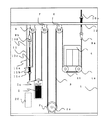
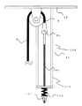
図1は本発明の一実施形態であるロープの伸び調整装置を設置したエレベータの昇降路縦断面図、図2は図1の要部拡大図である。尚、図において、従来の技術で説明したものと同一のものは、同一の符号で示している。
【0016】
本実施形態において、従来の技術の構成と異なる点は、ロープ端固定部100及びその近傍の構成にあり、その他はほぼ同一である。
【0017】
図1に示すように、頂部ビーム12には転向プーリ8が新たに設けられており、つり合いおもりプーリ5aに巻き掛けられた後、昇降路1内頂部近傍へ配設されたロープ3は、前記転向プーリ8に巻き掛けられて方向転換し下方へ垂下している。
【0018】
そして前記ロープ端固定部100は、この垂下したロープ3端部に取付けられたシンブルロッド9bと、このシンブルロッド9bに取付けられその外周に雄ねじを備えた調整ロッド10cと、この調整ロッド10cを垂直方向に変位可能とするロッド固定部材11とから構成されている。
【0019】
そしてロッド固定部材11は、その一端が前記転向プーリ8に他端が前記頂部プーリ12に取付けられ前記調整ロッド12が挿入される略U字状の固定ブラケット11aと、この固定ブラケット11aに当接するとともに前記調整ロッド12が挿入されるバネ部材11bと、前記調整ロッド12の端部に螺合し、前記固定ブラケット11aとの間で前記バネ部材11bを挟持するナット11cとを備えて構成されている。
【0020】
さらにこのロープ端固定部100は、前記乗かご4の走行を制御する制御盤20の垂直方向投影面上に位置するよう配設したことを特徴とする。
【0021】
従って、本発明のロープの伸び調整によれば、前記調整ロッド10cの長さを十分に取っておけば、前記ナット11cを締め上げることにより、調整ロッド10cを昇降路下方に向けて垂下させることが可能であり、十分にロープ伸びの調整代を確保することができる。
【0022】
さらに、ロープ端固定部100は、通常、昇降路内機器の配設されない制御盤20の垂直方向投影面上に位置するよう配設したため、他の昇降路内機器に干渉することなく、その固定エリアを確保し容易に配設することができる。
【0023】
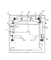
次に、本発明の他の実施形態であるエレベータロープの伸び調整装置を図3、図4を用いて説明する。図3は本発明の他の実施形態であるロープの伸び調整装置の要部拡大図、図4は本発明の他の実施形態であるロープの伸び調整装置の設置状態を示す昇降路水平断面図である。
【0024】
他の実施形態におけるロープ端固定部100は、固定ブラケット111aがつり合いおもり5の走行をガイドするガイドレール16に取付けられる点で前実施形態と異なっている。このロッド固定部材111aは、レールクリップ18とボルト17とナット19によりガイドレール16に固定されている。
【0025】
また図4に示すように、ロープ端固定部111aは、通常、昇降路内機器の配設されない制御盤20の垂直方向投影面上に位置するよう配設したため、他の昇降路内機器に干渉することなく、その固定エリアを確保し容易に配設することができる。また、他の実施形態によれば、ガイドレール16に固定する構成であるため、ロッド固定部材111aを小形なものとすることができる。
【0026】
【発明の効果】
本発明は、上記のようにエレベータのロープ伸び調整装置を構成したため、機械室レスエレベータにおいても、ロープ伸びの調整を円滑に行うことを可能とするとともにその設置を良好に行うことができる。
【図面の簡単な説明】
【図1】本発明の一実施形態であるロープの伸び調整装置を設置したエレベータの昇降路縦断面図である。
【図2】図2は図1の要部拡大図である。
【図3】本発明の他の実施形態であるロープの伸び調整装置の要部拡大図である。
【図4】本発明の他の実施形態であるロープの伸び調整装置の設置状態を示す昇降路水平断面図である。
【図5】一般的な機械室レスエレベータの全体構成を示す昇降路縦断面図である。
【符号の説明】
1 昇降路
2 巻上げ機
3 ロープ
4 乗かご
5 つり合いおもり
5a つり合いおもりプーリ
8 転向プーリ
10c 調整ロッド
11 ロッド固定部材
12 頂部ビーム
16 つり合いおもりガイドレール
20 制御盤
100 ロープ端固定部[0001]
TECHNICAL FIELD OF THE INVENTION
BACKGROUND OF THE INVENTION 1. Field of the Invention The present invention relates to a car for elevating and lowering in a lift furnace and an elongation adjusting device for an elevator rope for lifting a counterweight.
[0002]
[Prior art]
2. Description of the Related Art In recent years, elevators without a machine room capable of reducing the occupied volume ratio in a building tend to be equipped with machine room-less elevators. This elevator without machine room is generally configured as shown in FIG.
[0003]
Here, FIG. 5 is a hoistway vertical sectional view showing the entire configuration of a general machine room-less elevator.
[0004]
As shown in the figure, the rope 3 of the machine room-less elevator has both ends fixed to the top beam 12 via thimble rods 9a, 9b and rods 10a, 10b attached to both ends thereof.
[0005]
Further, as shown in the figure, an intermediate portion of the rope 3 includes a car lower pulley 4a, 4b provided on the car 4, a turning pulley 6 provided on the top beam 12, a traction sheave 2a of the hoist 2, The diverting pulley 7 provided on the top beam 12 and the counterweight pulley 5a provided on the counterweight 5 are roped so as to be wound respectively.
[0006]
By the way, in the above-described roping elevator, if the rods 10a and 10b are displaced upward toward the top of the hoistway 1, the length correction for the elongation of the rope 3 is possible. There was only 400 to 500 mm to the top, and there was an inconvenience that the adjustment allowance for rope elongation could not be sufficiently secured.
[0007]
In order to solve this inconvenience, if the rods 10a and 10b are displaced toward the lower part of the hoistway, it is effective in securing the adjustment margin. As a prior art disclosed in this regard, there has been proposed a technique in which a rope end attached to the top of the hoistway 1 is attached to face down the hoistway 1 (for example, see Patent Document 1).
[0008]
[Patent Document 1]
Japanese Utility Model Publication No. 60-96363 (page 7, line 18-page 8, line 4, FIG. 5)
[0009]
[Problems to be solved by the invention]
However, since the elevator described in Patent Document 1 has a machine room, it is easy to secure an area for fixing the rope end. However, in an elevator without a machine room, there are many elevators near the top of the hoistway. Therefore, it was difficult to secure the rope end area.
[0010]
The present invention has been made in view of the above-described problems, and an object of the present invention is to make it possible to smoothly adjust a rope elongation in a machine room-less elevator and to easily install an elevator rope elongation adjustment. It is to provide a device.
[0011]
[Means for Solving the Problems]
In order to achieve the above object, the present invention has two ends fixed to the vicinity of the top of the hoistway, a pulley provided at the middle portion of the car and the counterweight, and an extension of the elevator rope wound around the hoist. In the adjusting device, after being wrapped around the counterweight pulley, a turning pulley is provided at a fixed position of a rope end fixed near the top of the hoistway, and the rope end is wound around the turning pulley. Further, a rope end fixing portion is provided for vertically adjustable adjustment while hanging down the hoistway, and the rope end fixing portion is further provided with a vertical projection surface of a control panel for controlling the traveling of the car. It is characterized by being arranged so as to be located above.
[0012]
According to the present invention, the rope end fixing portion is configured as described above, and the position can be adjusted downward in the hoistway, so that even in a machine room elevator having a limited dimension up to the hoistway top, the adjustment allowance is required. We can secure enough.
[0013]
Further, since the rope end fixing portion is disposed so as to be located on the vertical projection plane of the control panel, which is normally not provided, the fixing area can be easily secured without interfering with other equipment in the hoistway. Can be arranged.
[0014]
BEST MODE FOR CARRYING OUT THE INVENTION
Hereinafter, an elongation adjusting device for an elevator rope according to an embodiment of the present invention will be described with reference to FIGS.
[0015]
FIG. 1 is a vertical sectional view of a hoistway of an elevator provided with a rope elongation adjusting device according to an embodiment of the present invention, and FIG. 2 is an enlarged view of a main part of FIG. In the drawings, the same components as those described in the related art are denoted by the same reference numerals.
[0016]
The present embodiment differs from the conventional technology in the configuration of the rope end fixing portion 100 and the configuration in the vicinity thereof, and the other configurations are substantially the same.
[0017]
As shown in FIG. 1, a turning pulley 8 is newly provided on the top beam 12, and after being wound around the counterweight pulley 5 a, the rope 3 arranged near the top of the hoistway 1 is connected to the above-described rope 3. It is wrapped around the diverting pulley 8 to change direction and hang down.
[0018]
The rope end fixing portion 100 is vertically connected to a thimble rod 9b attached to the end of the hanging rope 3, an adjustment rod 10c attached to the thimble rod 9b and having an external thread on its outer periphery, and an adjustment rod 10c. And a rod fixing member 11 which can be displaced in the direction.
[0019]
The rod fixing member 11 has one end attached to the deflection pulley 8 and the other end attached to the top pulley 12, and a substantially U-shaped fixing bracket 11 a into which the adjustment rod 12 is inserted, and abuts the fixing bracket 11 a. A spring member 11b into which the adjustment rod 12 is inserted, and a nut 11c screwed to an end of the adjustment rod 12 and holding the spring member 11b between the fixing bracket 11a. I have.
[0020]
Further, the rope end fixing portion 100 is provided so as to be located on a vertical projection plane of a control panel 20 for controlling the traveling of the car 4.
[0021]
Therefore, according to the rope elongation adjustment of the present invention, if the adjustment rod 10c has a sufficient length, the nut 11c is tightened to cause the adjustment rod 10c to hang down the hoistway. It is possible to secure sufficient adjustment allowance for rope elongation.
[0022]
Furthermore, since the rope end fixing part 100 is normally disposed so as to be located on the vertical projection plane of the control panel 20 where the equipment in the hoistway is not installed, the fixing is performed without interfering with other equipment in the hoistway. An area can be secured and can be easily arranged.
[0023]
Next, an elevator rope elongation adjusting device according to another embodiment of the present invention will be described with reference to FIGS. FIG. 3 is an enlarged view of a main part of a rope elongation adjusting device according to another embodiment of the present invention. FIG. 4 is a horizontal sectional view of a hoistway showing an installed state of a rope elongation adjusting device according to another embodiment of the present invention. It is.
[0024]
The rope end fixing portion 100 according to another embodiment is different from the previous embodiment in that a fixing bracket 111a is attached to a guide rail 16 that guides the running of the counterweight 5. The rod fixing member 111a is fixed to the guide rail 16 by a rail clip 18, a bolt 17, and a nut 19.
[0025]
In addition, as shown in FIG. 4, the rope end fixing portion 111a is usually disposed so as to be located on the vertical projection plane of the control panel 20 in which the equipment in the hoistway is not provided. Without fixing, the fixed area can be secured and easily arranged. Further, according to another embodiment, since the rod fixing member 111a is configured to be fixed to the guide rail 16, the rod fixing member 111a can be reduced in size.
[0026]
【The invention's effect】
According to the present invention, since the rope elongation adjusting device for an elevator is configured as described above, even in an elevator without a machine room, it is possible to smoothly adjust the elongation of the rope and to install the rope well.
[Brief description of the drawings]
FIG. 1 is a vertical sectional view of a hoistway of an elevator provided with a rope elongation adjusting device according to an embodiment of the present invention.
FIG. 2 is an enlarged view of a main part of FIG.
FIG. 3 is an enlarged view of a main part of a rope elongation adjusting device according to another embodiment of the present invention.
FIG. 4 is a hoistway horizontal sectional view showing an installed state of a rope elongation adjusting device according to another embodiment of the present invention.
FIG. 5 is a vertical sectional view of a hoistway showing the overall configuration of a general machine room-less elevator.
[Explanation of symbols]
DESCRIPTION OF SYMBOLS 1 Hoistway 2 Hoist 3 Rope 4 Riding car 5 Counterweight 5a Counterweight pulley 8 Turning pulley 10c Adjusting rod 11 Rod fixing member 12 Top beam 16 Counterweight guide rail 20 Control board 100 Rope end fixing part