【0001】
【発明の属する技術分野】
本発明は、固液分離のための濾過機及び濾過装置に関するものであり、特には合流式下水道の越流水の固液分離のための濾過機及び濾過装置に関するものである。
【0002】
下水道の方式は分流式と合流式とに大別される。分流式下水道は雨水と汚水が別々の管を流れるものであり、雨水は雨水管を通って河川、湖沼、海等の下流水域へ放流され、汚水は汚水管を通って下水処理場へ流入し、処理された後に下流水域へ放流される。
【0003】
合流式下水道は雨水と汚水が同一の管を流れるものであり、図11はその1例を示すフロー図であり、以下図11を参照して合流式下水道の1例を説明する。雨水枡101からの雨水と汚水源102からの汚水は合流下水管103に流入して合流汚水111となり越流堰104Aを具備する雨水吐き室104へ流入する。晴天時には合流汚水111は越流堰104Aを越えず、処理場流入管105を通って下水処理場106へ流入し、処理後、処理水放流管107を通って下流水域へ放流される。処理場流入管105へ流入させ得る水量の上限が越流堰104Aの高さにより設定されていて、大雨等で水量が増大して前記上限を上回ると、上回った分は越流堰104Aを越えて越流水となり下水処理場を経ることなく放流管110を通って直接下流水域へ放流される。このように汚水を含む越流水が処理されないまま下流水域へ放流されると汚染の原因となるので、最近では放流管110の途中に濾過機(図示せず)を設け、この濾過機に越流水を流入させて侠雑物を除去後、放流することが多い。
【0004】
前記濾過機には種々のものがあり、例えば特許文献1には、ドラムの一端から固体分を含む液体が供給される濾過機が示されているので、図面を参照しながら前記濾過機について説明する。図12は濾過機及び槽の斜視図であり、濾過機が見えるようにするため槽を破断して図示している。図13は濾過機の側断面図であり、後述する図14のF−F断面図である。図14は図13のE−E断面図である。
【0005】
ドラム902、環状フィルタ909、樋903及び洗浄装置907を有する濾過機901が槽980に設置される。ドラム902及び環状フィルタ909は水平軸線Aの周りに回転自在に設けられ、樋903及び洗浄装置907は固定して設けられる。環状フィルタ909のフィルタ室911(図13)は、外周部は保持フレーム931(図14)で、両側面部はマイクロフィルタ布921を有するフィルタセグメント920(図14)で、内周部はドラム902で囲われていて、前記内周部のドラム902の開口904を通してドラム902と連通している。
【0006】
回転しない状態で、ドラム902に流入した固体分を含む液体905が開口904を通ってフィルタ室911に入り、フィルタセグメント920のマイクロフィルタ布921により濾過されて、液体分はマイクロフィルタ布921を通過して槽980内に貯留された後槽980外に流出し、固体分はマイクロフィルタ布921の下方部に捕捉されてフィルタ室911内に留まる。このように液体905が、ドラム902からフィルタ室911を介してマイクロフィルタ布921を通過する経路が液体導管906を形成する。
【0007】
環状フィルタ909の下方部のマイクロフィルタ布921に捕捉された固体分の量が増大してマイクロフィルタ布921が目詰まり状態になると、ドラム902及びこれに固着された環状フィルタ909が回転し、マイクロフィルタ布921に捕捉された固体分が前記回転により下方部から上方部に移動し、上方部に設置された洗浄装置907から噴射された水により剥離され目詰まり状態が解消される。前記水と剥離された固体分は樋903に受けられて排出される。以下本明細書においては、このようにフィルタに捕捉された固体分に流体(例えば水)を噴射して剥離し目詰まり状態を解消することを「洗浄」と記述する。この濾過機901は濾過面積を大きくすることができ、洗浄も洗浄装置907から噴射された水により容易に行えるという利点を有する。
【0008】
【特許文献1】
国際公開WO99/30797号公報
【0009】
【発明が解決しようとする課題】
ところで下水道を流れる汚水に油分が多く含有されていると、下水管の内壁に油分が付着する。特に合流式下水道では雨天時に大量の雨水が下水道に流入すると、付着していた油分が剥離して油塊となって越流水とともに流下して下流水域を汚染する。下水処理場で処理されない越流水中の前記油塊が濾過機901に流入しマイクロフィルタ布921に捕捉される。合流式下水道で越流水が生じるのは大雨等で水量が増大した時であり、このような時は前述のように油塊が合流下水とともに流下する現象が顕著になり、濾過機901に流入しマイクロフィルタ布921に捕捉される油塊も多くなる。前記油塊はマイクロフィルタ布921に強く捕捉され、さらにマイクロフィルタ布921に捕捉された油塊以外の固体分も油塊の油分が付着するとより強く捕捉され、洗浄装置907から噴射された水では洗浄が十分行われなくなるという問題点が有った。
【0010】
下水道以外でも、油分を多く含有する排水が濾過機901に流入すると、マイクロフィルタ布921に捕捉された固体分に付着した油分が固まることにより、前記固体分がマイクロフィルタ布921に強く捕捉され、洗浄装置907から噴射された水では洗浄が十分行われなくなるという問題点が有った。
【0011】
本発明は前記問題点に鑑みなされたものであり、その目的とするところは油分を含有する液体の濾過を容易に行える濾過機及び濾過装置を提供することであり、特には油塊を含有する合流式下水道の越流水の濾過を容易に行える濾過機及び濾過装置を提供することである。
【0012】
【課題を解決するための手段】
本発明者らは種々研究の結果、次のような濾過機及び濾過装置とすることにより前記問題点を解決し、本発明を完成するに至った。すなわち本発明は、回転自在に設けられたフィルタで液体を濾過する濾過機において、高温流体を前記フィルタに噴射する洗浄装置を設けるとともに、前記フィルタの材料を耐熱性を有するものとしたことを特徴とする濾過機である。
【0013】
本発明において前記洗浄装置は移動可能に設置され前記フィルタ全面に高温流体を噴射することができることが好ましい。
【0014】
本発明において高温流体は水蒸気、熱水または油分を分解する効果を有する酸性水溶液またはアルカリ性水溶液の蒸気又は熱水のような高温流体としても良く、あるいはそれらを併用しても良い。
【0015】
前記フィルタは前記高温流体と接触しても劣化や腐蝕等の変化の生じることの無い材質で形成されていることが望ましく、例えば金属フィルタ、セラミックフィルタ、耐熱性樹脂フィルタ等を好適に使用できる。
【0016】
本発明の濾過機は、合流式下水道の越流水の濾過に特に好適に使用できる。
【0017】
【発明の実施の形態】
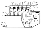
以下、本発明の実施形態について図面を参照して説明する。図1は本実施形態の濾過装置100の斜視図であり、液体5の流入方向は図の紙面右から左であり、濾過機1が見えるようにするため槽80を破断して示し、ドラム2の開放端(後述)の上半分、最も開放端側のフィルタセグメント20の上半分、その内部のスポーク43ならびに最も開放端側の枝管7Bの下部及びそれに取り付けられるノズル7Cは図示を省略して環状フィルタ9の内部が見えるようにするとともに、開放端支持部62、閉鎖端支持部73及び駆動部78は図示を省略している。図2は液体5の流入側から見た濾過装置100の正面図である。図3は図2のA−A断面図であり、閉鎖端支持部73及び駆動部78は断面にせず、濾過機1は樋3部分だけを断面で示す。図4は特にドラム2、保持フレーム31、スポーク43、空間9aを示す正面図である。図5は図4のB−B断面図である。図6はフィルタセグメント20を示す正面図である。図7は図4(詳しくは、図4のものを20度回転させた状態)のスポーク43にフィルタセグメント20が取り付けられた状態ならびに樋3及びノズル7Cを示す正面図であり、環2D及び堰板2Bの図示を省略した図である。図8は図7のC−C断面図である。図9は図7のD−D断面図である。図10は本発明の濾過装置を用いた合流式下水道の1例を示すフロー図であり、同一部は図11と同じ参照符号を付す。
【0018】
濾過装置100は濾過機1及びコンクリート製の槽80を有する。濾過機1はドラム2、樋3、洗浄装置7、環状フィルタ9、開放端支持部62、閉鎖端支持部73、駆動部78及びそれらが取り付けられる躯体を有する。なお本実施形態では前記躯体を槽80で代用するので躯体は不要である。
【0019】
液体5が流入するドラム2は筒2A、堰板2B、環2D及びドラム用軸2E(図3)を有する。以下、本明細書では液体5が流入する側のドラム2の端部を「開放端」と記述し、液体5が流入する側と反対側のドラム2の端部を「閉鎖端」と記述し、筒2Aの長手方向を「軸方向」と記述する。筒2Aは円筒形で閉鎖端は袋状に閉塞され、開放端は中心部に流入穴2Baを有する堰板2Bで一部閉塞されている。筒2Aの開放端には環2Dが同軸に外設され、閉鎖端にはドラム用軸2Eが同軸に突設される。筒2Aの後述するフィルタ室11の位置には開口2cを設ける。
【0020】
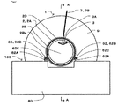
環状フィルタ9は、フィルタセグメント20、保持フレーム31、スポーク43及びボルト35を有する。図4に示されるスポーク43は図7ではフィルタセグメント20に隠されて見えない。板状のスポーク43はネジ穴43a(図4)を有し、長手方向の一端がドラム2の外周に2枚1組で軸方向にL1寸法(図5、8)の間隔を置いて配設される。スポーク43の長手方向の他端には円環状の保持フレーム31が取り付けられる。このようにドラム2、保持フレーム31及びスポーク43で囲われた略扇形の空間9a(図4)が形成される。本実施形態では空間9aの数は(円周方向に40度ピッチで)9箇所とした。そして前記9箇所の空間9aを含む環状フィルタ9がドラム2の軸方向に間隔を空けて複数取り付けられる。
【0021】
フィルタセグメント20はフィルタ21及びフィルタフレーム22を有する。フィルタ21の平面形状は空間9aよりもやや狭い略扇形(図6の破線で示す)であり、フィルタセグメント20が形成されたとき後述するボルト通し穴22aと重ならない形状とする。フィルタフレーム22の平面形状はフィルタ21の外枠となるような窓形であり、内外周が空間9aに緩挿可能な寸法にする。フィルタフレーム22はネジ穴43aの位置に対応したボルト通し穴22aを有する。フィルタ21がフィルタフレーム22に溶接、ろう付けあるいは接着等の固着手段により固着されてフィルタセグメント20が形成される。フィルタセグメント20が前記2枚1組のスポーク43に軸方向の両側から取り付けられ、ボルト通し穴22aを通したボルト35がネジ穴43aにねじ込まれ、フィルタセグメント20がスポーク43に締結される。
【0022】
空間9aの軸方向両側面部がフィルタ21有するフィルタセグメント20で囲われてフィルタ室11が形成される。本実施形態では回転方向に隣接する9箇所のフィルタ室11間には、仕切りが無くつながったものとする。環状フィルタ9のフィルタ室11は、外周部は保持フレーム31で、両側面部はフィルタ21を有するフィルタセグメント20で、内周部はドラム2で囲われていて、前記内周部のドラム2の筒2Aの開口2cを通してドラム2と連通している。開口2cの軸方向寸法L2(図9)はフィルタ室11の軸方向寸法L1に対してL2≦L1となるようにし、ドラム2の強度を損なわない範囲でできるだけ大きくすることが好ましい。開口2cの周方向寸法L3(図7)はドラム2の強度を損なわない範囲でできるだけ大きくすることが好ましい。L2あるいはL3が小さいと、後述する洗浄により剥離落下する固形物の開口2cの通過に支障を来たす。
【0023】
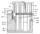
樋3は、長手方向において開放端側が低くなるように傾斜してドラム2内上部に設けられ、開放端側はドラム2外に位置する。樋3の閉鎖端側端部には堰板3Aが具備され、後述する洗浄排液5Bの溢出を防止する。樋3は槽80に固定して取り付けられるが、樋3位置及び前記傾斜角度を調整可能にしておくと、液体5の性状が変化した場合の対応が容易であるし、試運転時の調整にも便利であり好ましい。
【0024】
洗浄装置7は元管7A、枝管7B及びノズル7Cを有する。元管7Aは環状フィルタ9の上側に略水平に配設される。枝管7Bは元管7Aの下部に連通して、軸方向に隣接する環状フィルタ9の間隔部に、略垂直に配設される。枝管7Bに配設されるノズル7Cは環状フィルタ9に対向しており高温流体7Dを環状フィルタ9に噴射する。このとき環状フィルタ9を回転させることにより環状フィルタ9全面を洗浄することができる。環状フィルタ9全面を残さず洗浄するにはノズル7Cを密に配置する必要がありノズル数が多くなる。ノズル数が多いと高温流体の供給源の容量も大きくする必要が生じ設備コストが増大する。少ないノズル数で環状フィルタ9全面を残さず洗浄するにはノズル7Cを回転する環状フィルタ9の径方向に移動可能に設置すれば良い。例えばノズル7Cを環状フィルタ9の濾過面に対して平行面上を揺動させるのである。又は直線移動であっても良い。ノズル7Cを移動可能にするには洗浄装置7全体を移動させるとよい。洗浄装置7は槽80に固定して取り付けられるが、ノズル7C位置を調整可能にしておくと、液体5の性状が変化した場合の対応が容易であるし、試運転時の調整にも便利であり好ましい。前記ノズル7C位置を調整可能にしておく方法の一例として、元管7A及び/又は枝管7Bの一部あるいは途中にフレキシブル継ぎ手あるいはねじ込み継ぎ手等を設置してことが行われる。1本の枝管7Bに配設されるノズル7Cの数は単数あるいは複数個のいずれでも良く機能を満足する任意の数とすれば良い。そして枝管7Bに配設されたノズル7Cの間あるいは上端のノズル7Cの上もしくは下端のノズル7Cの下にノズル取り付け可能なネジ穴を設け、そこを栓で閉じておき、必要に応じてノズル取り付け可能にしておくと、前述のような液体5の性状が変化した場合の対応が容易であるし、試運転時の調整にも便利であり好ましい。
【0025】
開放端支持部62(図2、3)は開放端支持板62A、円筒62B及び円筒用軸62Cを有する。円筒用軸62Cは円筒62Bを軸通し、両端が2枚の開放端支持板62Aに軸装される。開放端支持板62Aは槽80に取り付けられる。このようにして円筒62Bが槽80に対して回転自在に設けられる。槽80に取り付けられた閉鎖端支持板72に、ドラム用軸2Eが回転自在に軸装される。ドラム用軸2E及び閉鎖端支持板72が閉鎖端支持部73を形成する。2組の開放端支持部62の円筒62Bが環2Dの両側面下部に当接し、閉鎖端支持部73とともに、ドラム2を回転自在に槽80に支持する。開放端支持部62あるいは閉鎖端支持部73に必要に応じてベアリング装置を具備することは回転を円滑にするために有効である。
【0026】
ドラム用軸2Eの端部には従動スプロケット74が取り付けられる。槽80に取り付けられた駆動装置である電動機75の出力軸には、駆動スプロケット76が軸方向位置を従動スプロケット74に合わせて取り付けられ、チェン77を介して駆動スプロケット76の回転を従動スプロケット74に伝道できるので、電動機75の回転出力をドラム用軸2Eならびにそれに固着されたドラム2及び環状フィルタ9に伝道し、ドラム2及び環状フィルタ9を回転させることができる。電動機75、駆動スプロケット76、従動スプロケット74及びチェン77から駆動部78が形成される。
【0027】
このようにドラム2及びドラム2に取り付けられた環状フィルタ9は回転自在に槽80に設けられる。前述のように本実施形態では躯体を槽80で代用し躯体は不要としたが、躯体を槽80で代用せず躯体を用いる場合は開放端支持板62A、閉鎖端支持板72及び電動機75は躯体に取り付けられる。
【0028】
濾過機1の材料の内、鉄製のものについては、少なくともその一部をメッキ付あるいはSUS304、SUS316等のステンレルスチール製とすると、腐食しにくく寿命を長くできるので好ましい。
【0029】
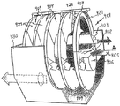
回転しない状態で、流入穴2Baからドラム2に流入した固体分ならびに油分及び/又は油塊を含む液体5が開口2cを通って下方のフィルタ室11に流入し、フィルタセグメント20のフィルタ21により濾過されて、液体分である濾過液5A(図1)はフィルタ21を通過してフィルタ室11から槽80内に移動し、流出口80a(図1、3)から槽80外に流出し、固体分(図示せず)はフィルタ21に捕捉されて下方のフィルタ室11内に留まる。
【0030】
下方のフィルタ室11のフィルタ21に捕捉された前記固体分の量が増大してフィルタ21が目詰まり状態になると、ドラム2を図7において、矢印方向に40度回転させ(すなわちドラム2に固着された環状フィルタ9を40度回転させ)目詰まりした環状フィルタJを矢印方向に移動させ、目詰まりしていない隣接する環状フィルタKを下方(回転させる前に環状フィルタJが存在していた位置)に移動させる。回転と同時に洗浄装置7から流体7Dを噴射して環状フィルタLを洗浄して目詰まりを解消する。前記目詰まり状態を検出し環状フィルタ9を回転させる操作もしくは制御は、人が目視等で検出し、電動機75を駆動するようにしても良いが、例えばレベル計(図示せず)により目詰まり状態にともなうドラム2の液体5の液面上昇を検出して電動機75を駆動するようにしても良い。
【0031】
ところで、この捕捉された固体分に付着した(あるいは含有された)前記油分及び/又は油塊が固まることにより、前記固体分がフィルタ21に強く捕捉され、図12を参照して説明した従来の濾過機では洗浄が十分行われなくなる。そこで本実施形態では、捕捉された固体分に洗浄装置7から噴射する流体7Dを水蒸気とし、前記水蒸気の熱により固まった油分及び/又は油塊を溶解するとともに、水蒸気の噴射圧力により固体分をフィルタ21から剥離して洗浄するようにした。洗浄された固体分及び油分及び/又は油塊ならびに前記水蒸気の凝縮水である洗浄排液5B(図1)は落下し、開口2cを通って樋3に受け止められて排出される。
【0032】
フィルタ21の材料は金属フィルタ、セラミックフィルタあるいは耐熱性樹脂フィルタのいずれでも良く、噴射される水蒸気の熱に耐えられる耐熱性を有する任意の材料とすることができる。合流式下水道の越流水を濾過する濾過機の場合は、フィルタ21の材料として金網あるいはエキスパンドメタルのような比較的目の大きもの(これらは広義の金属膜である)が選択され、前記金網あるいはエキスパンドメタルは、メッキ付鉄製あるいはSUS304、SUS316等のステンレルスチール製とすると、腐食しにくく寿命を長くできるので好ましい。前記目の大きさは濾過しようとする液体の性状に応じて適切に設定される。1台のフィルタ21の材料及び/又は目の大きさが異なるものを組み合わせても良い。そして、合流式下水道の(越流水でなく)合流下水を濾過する濾過機、分流式下水道の雨水又は汚水を濾過する濾過機あるいは下水道以外の排水の侠雑物を濾過する濾過機の場合も同様である。
【0033】
このような濾過装置100が設置された合流式下水道の1例を図10のフロー図を参照して説明する。雨水枡101からの雨水と汚水源102からの汚水は合流下水管103に流入して合流汚水111となり越流堰104Aを具備する雨水吐き室104へ流入する。通常、合流汚水111は越流堰104Aを越えず、処理場流入管105を通って下水処理場106へ流入し、処理後、処理水放流管107を通って下流水域へ放流される。そして処理場流入管105へ流入させ得る水量の上限が越流堰104Aの高さにより設定されていて、大雨等で水量が増大して前記上限を上回ると、上回った分は越流堰104Aを越えて越流水となり下水処理場へ流入せず、放流管108を通って濾過装置100へ流入し、濾過後、濾過液5Aは濾過液放流管112を通って下流水域へ放流され、洗浄排液5Bは洗浄排液流入管109を通って下水処理場106へ流入し、処理後、処理水放流管107を通って下流水域へ放流される。このように越流水を直接下流水域へ放流せず、濾過装置100で濾過後、放流することにより下流水域を汚濁する度合いを軽減できる。
【0034】
なお、分流式下水道でも汚水管において油塊が生じるが、汚水が全量下水処理場で処理されるので放流先の下流水域を汚濁するという問題は無い。分流式下水道の雨水管において油塊が生じる場合があるが、極めて少量であるので放流先の下流水域を著しく汚濁するという問題は無いが、汚水管の途中に濾過装置100を設置して濾過後、放流することにより下流水域の汚濁防止をより高度に行うことができる。
【0035】
【発明の効果】
本発明によれば、油分を含有する液体の濾過機及び濾過装置において、フィルタに捕捉された固体分に付着した(あるいは含有された)油分が固まって、従来の洗浄では剥離困難となった場合でも、洗浄装置7から噴射する流体7Dを水蒸気あるいは熱水のような高温流体とし、前記高温流体の熱により固まった油分を溶解するとともに、高温流体の噴射圧力により固体分をフィルタ21から剥離して洗浄するようにしたことにより、油分を含有する液体の濾過を容易に行える濾過機及び濾過装置を提供することができる。特に、本発明によれば合流式下水道の油塊を含む越流水の濾過を容易に行える濾過機及び濾過装置を提供することができる。
【図面の簡単な説明】
【図1】実施形態の濾過装置の斜視図である。
【図2】濾過装置の正面図である。
【図3】図2のA−A断面図である。
【図4】ドラム2、保持フレーム31、スポーク43、空間9aを示す正面図である。
【図5】図4のB−B断面図である。
【図6】フィルタセグメント20を示す正面図である。
【図7】図4のスポーク43にフィルタセグメント20が取り付けられた状態ならびに樋3及びノズル7Cを示す正面図である。
【図8】図7のC−C断面図である。
【図9】図7のD−D断面図である。
【図10】本発明の濾過装置を用いた合流式下水道の1例を示すフロー図である。
【図11】従来の合流式下水道の1例を示すフロー図である。
【図12】従来の濾過機及び槽の斜視図である。
【図13】従来の濾過機の側断面図であり、図14のF−F断面図である。
【図14】図13のE−E断面図である。
【符号の説明】
1 濾過機
2 ドラム
2A 筒
2B 堰板
2Ba 流入穴
2c 開口
2D 環
2E ドラム用軸
3 樋
3A 堰板
5 液体
5A 濾過液
5B 洗浄排液
7 洗浄装置
7A 元管
7B 枝管
7C ノズル
7D 高温流体
9、J、K、L 環状フィルタ
9a 空間
11 フィルタ室
20 フィルタセグメント
21 フィルタ
22 フィルタフレーム
22a 穴
31 保持フレーム
35 ボルト
43 スポーク
43a ネジ穴
62 開放端支持部
62A 開放端支持板
62B 円筒
62C 円筒用軸
72 閉鎖端支持板
73 閉鎖端支持部
74 従動スプロケット
75 電動機
76 駆動スプロケット
77 チェン
78 駆動部
80 槽
80a 流出口
100 濾過装置
101 雨水枡
102 汚水源
103 合流下水管
104 雨水吐き室
104A 越流堰
105 処理場流入管
106 下水処理場
107 処理水放流管
108 放流管
109 洗浄排液流入管
111 合流汚水
112 濾過液放流管[0001]
TECHNICAL FIELD OF THE INVENTION
The present invention relates to a filter and a filtration device for solid-liquid separation, and more particularly to a filter and a filtration device for solid-liquid separation of overflow water of a combined sewer.
[0002]
The sewer system is roughly divided into a split type and a combined type. In a sewer system, rainwater and sewage flow through separate pipes.Rainwater is discharged through stormwater pipes to downstream water bodies such as rivers, lakes, the sea, etc. After treatment, it is discharged to downstream waters.
[0003]
In the combined sewer system, rainwater and sewage flow through the same pipe. FIG. 11 is a flow chart showing one example of the combined sewer system. One example of the combined sewer system will be described below with reference to FIG. The rainwater from the rainwater basin 101 and the sewage from the sewage source 102 flow into the combined sewer 103 and become the combined sewage 111 and flow into the rainwater discharge chamber 104 having the overflow weir 104A. In fine weather, the combined sewage 111 does not pass through the overflow weir 104A, flows into the sewage treatment plant 106 through the treatment plant inflow pipe 105, and is discharged to the downstream water area through the treated water discharge pipe 107 after treatment. The upper limit of the amount of water that can flow into the treatment plant inflow pipe 105 is set by the height of the overflow weir 104A. When the amount of water increases due to heavy rain or the like and exceeds the upper limit, the excess exceeds the overflow weir 104A. The water becomes overflow water and is discharged directly to the downstream water area through the discharge pipe 110 without passing through the sewage treatment plant. If the overflow water including sewage is discharged into the downstream water area without being treated, it may cause contamination. Recently, a filter (not shown) is provided in the middle of the discharge pipe 110, and the overflow water is provided to the filter. Is often released after removal of intriguing foreign matters.
[0004]
There are various types of the filter. For example, Patent Document 1 discloses a filter in which a liquid containing a solid component is supplied from one end of a drum. The filter will be described with reference to the drawings. I do. FIG. 12 is a perspective view of the filter and the tank, with the tank cut away to make the filter visible. FIG. 13 is a side sectional view of the filter, and is a sectional view taken along line FF of FIG. 14 described later. FIG. 14 is a sectional view taken along line EE of FIG.
[0005]
A filter 901 having a drum 902, an annular filter 909, a gutter 903, and a washing device 907 is installed in a tank 980. The drum 902 and the annular filter 909 are rotatably provided around a horizontal axis A, and the gutter 903 and the cleaning device 907 are fixedly provided. The filter chamber 911 (FIG. 13) of the annular filter 909 has a holding frame 931 (FIG. 14) on the outer periphery, a filter segment 920 (FIG. 14) having a micro filter cloth 921 on both sides, and a drum 902 on the inner periphery. It is enclosed and communicates with the drum 902 through the opening 904 of the drum 902 on the inner periphery.
[0006]
In a state where the drum 902 does not rotate, the liquid 905 containing the solid component flowing into the drum 902 enters the filter chamber 911 through the opening 904 and is filtered by the micro filter cloth 921 of the filter segment 920, and the liquid component passes through the micro filter cloth 921. Then, after being stored in the tank 980, it flows out of the tank 980, and the solid content is captured by the lower portion of the microfilter cloth 921 and stays in the filter chamber 911. Thus, the path through which the liquid 905 passes from the drum 902 through the filter chamber 911 to the micro filter cloth 921 forms the liquid conduit 906.
[0007]
When the amount of solids captured by the micro filter cloth 921 below the annular filter 909 increases and the micro filter cloth 921 becomes clogged, the drum 902 and the annular filter 909 fixed thereto rotate, and the micro filter cloth 921 rotates. The solid matter captured by the filter cloth 921 moves from the lower part to the upper part by the rotation, and is separated by the water jetted from the cleaning device 907 installed at the upper part, so that the clogged state is eliminated. The solids separated from the water are received by the gutter 903 and discharged. Hereinafter, in the present specification, the term “washing” refers to jetting a fluid (for example, water) to the solid content captured by the filter to remove the clogged state. This filter 901 has an advantage that the filtration area can be increased and the washing can be easily performed by the water jetted from the washing device 907.
[0008]
[Patent Document 1]
International Publication WO99 / 30797 [0009]
[Problems to be solved by the invention]
If the wastewater flowing through the sewer contains a large amount of oil, the oil adheres to the inner wall of the sewer pipe. In particular, in a combined sewer system, if a large amount of rainwater flows into the sewer system in rainy weather, the attached oil is separated and forms oil lumps and flows down together with the overflow water to pollute the downstream water area. The oil lumps in the overflow water not treated in the sewage treatment plant flow into the filter 901 and are captured by the microfilter cloth 921. Overflow water occurs in the combined sewer when the amount of water increases due to heavy rain or the like. In such a case, the phenomenon that the oil lumps flow down together with the combined sewage becomes remarkable as described above, and flows into the filter 901. The amount of oil lumps captured by the micro filter cloth 921 also increases. The oil lumps are strongly captured by the microfilter cloth 921, and solids other than the oil lumps captured by the microfilter cloth 921 are more strongly captured when the oil content of the oil lumps adheres. There was a problem that washing was not performed sufficiently.
[0010]
In addition to the sewer, when wastewater containing a large amount of oil flows into the filter 901, the solid matter captured by the microfilter cloth 921 solidifies, and the solid matter is strongly captured by the microfilter cloth 921, There is a problem that the water jetted from the cleaning device 907 does not sufficiently perform the cleaning.
[0011]
The present invention has been made in view of the above problems, and it is an object of the present invention to provide a filter and a filtration device that can easily filter a liquid containing oil, particularly containing oil lumps. An object of the present invention is to provide a filtering device and a filtering device that can easily filter overflow water of a combined sewer.
[0012]
[Means for Solving the Problems]
As a result of various studies, the present inventors have solved the above problems by using the following filter and filter, and have completed the present invention. That is, the present invention is characterized in that, in a filter for filtering a liquid with a rotatably provided filter, a washing device for injecting a high-temperature fluid to the filter is provided, and the material of the filter has heat resistance. It is a filter machine.
[0013]
In the present invention, it is preferable that the cleaning device is movably installed and is capable of injecting a high-temperature fluid over the entire surface of the filter.
[0014]
In the present invention, the high-temperature fluid may be a high-temperature fluid such as steam or hot water of an acidic aqueous solution or an alkaline aqueous solution having an effect of decomposing steam, hot water, or oil, or may be used in combination.
[0015]
The filter is desirably made of a material that does not cause a change such as deterioration or corrosion even when it comes into contact with the high-temperature fluid. For example, a metal filter, a ceramic filter, a heat-resistant resin filter, or the like can be suitably used.
[0016]
INDUSTRIAL APPLICABILITY The filter of the present invention can be particularly suitably used for filtering overflow water of a combined sewer.
[0017]
BEST MODE FOR CARRYING OUT THE INVENTION
Hereinafter, embodiments of the present invention will be described with reference to the drawings. FIG. 1 is a perspective view of a filtration device 100 of the present embodiment. The inflow direction of the liquid 5 is from right to left in the drawing, and a tank 80 is cut away so that the filtration device 1 can be seen. The upper half of the open end (described later), the upper half of the filter segment 20 at the most open end, the spokes 43 therein, the lower part of the branch pipe 7B at the most open end, and the nozzle 7C attached thereto are not shown. The inside of the annular filter 9 is made visible, and the open end support 62, the closed end support 73, and the drive 78 are not shown. FIG. 2 is a front view of the filtration device 100 as viewed from the inflow side of the liquid 5. FIG. 3 is a cross-sectional view taken along line AA of FIG. 2, in which the closed end support portion 73 and the driving portion 78 are not shown in section, and the filter 1 shows only the gutter 3 in section. FIG. 4 is a front view particularly showing the drum 2, the holding frame 31, the spokes 43, and the space 9a. FIG. 5 is a sectional view taken along line BB of FIG. FIG. 6 is a front view showing the filter segment 20. FIG. 7 is a front view showing the filter segment 20 attached to the spokes 43 of FIG. 4 (specifically, the one shown in FIG. 4 rotated by 20 degrees), the gutter 3 and the nozzle 7C, and the ring 2D and the weir. It is the figure which omitted illustration of board 2B. FIG. 8 is a sectional view taken along line CC of FIG. FIG. 9 is a sectional view taken along the line DD of FIG. FIG. 10 is a flowchart showing an example of a combined sewer using the filtration device of the present invention, and the same parts are denoted by the same reference numerals as in FIG.
[0018]
The filtering device 100 has the filtering device 1 and a tank 80 made of concrete. The filter 1 has a drum 2, a gutter 3, a cleaning device 7, an annular filter 9, an open-end support 62, a closed-end support 73, a drive 78, and a frame to which they are attached. In the present embodiment, the skeleton is used in place of the tank 80, so that the skeleton is unnecessary.
[0019]
The drum 2 into which the liquid 5 flows has a cylinder 2A, a dam plate 2B, a ring 2D, and a drum shaft 2E (FIG. 3). Hereinafter, in this specification, the end of the drum 2 on the side where the liquid 5 flows in is described as “open end”, and the end of the drum 2 on the side opposite to the side where the liquid 5 flows in is described as “closed end”. , The longitudinal direction of the cylinder 2A is referred to as “axial direction”. The cylinder 2A is cylindrical and has a closed end closed in a bag shape, and an open end partially closed by a weir plate 2B having an inflow hole 2Ba in the center. A ring 2D is externally provided coaxially at the open end of the cylinder 2A, and a drum shaft 2E is coaxially protruded from the closed end. An opening 2c is provided at a position of a filter chamber 11, which will be described later, of the cylinder 2A.
[0020]
The annular filter 9 has a filter segment 20, a holding frame 31, spokes 43, and bolts 35. The spokes 43 shown in FIG. 4 are not visible in FIG. The plate-like spoke 43 has a screw hole 43a (FIG. 4), and one end in the longitudinal direction is disposed on the outer periphery of the drum 2 in a pair at a distance of L1 dimension (FIGS. 5 and 8) in the axial direction. Is done. The annular holding frame 31 is attached to the other end of the spoke 43 in the longitudinal direction. Thus, a substantially fan-shaped space 9a (FIG. 4) surrounded by the drum 2, the holding frame 31, and the spokes 43 is formed. In the present embodiment, the number of the spaces 9a is nine (at a pitch of 40 degrees in the circumferential direction). A plurality of annular filters 9 including the nine spaces 9a are attached at intervals in the axial direction of the drum 2.
[0021]
The filter segment 20 has a filter 21 and a filter frame 22. The planar shape of the filter 21 is a substantially sector shape (shown by a broken line in FIG. 6) slightly narrower than the space 9a, and does not overlap with a bolt through hole 22a described later when the filter segment 20 is formed. The planar shape of the filter frame 22 is a window shape that becomes the outer frame of the filter 21, and the inner and outer circumferences are set to dimensions that can be loosely inserted into the space 9a. The filter frame 22 has bolt through holes 22a corresponding to the positions of the screw holes 43a. The filter 21 is fixed to the filter frame 22 by a fixing means such as welding, brazing or bonding to form the filter segment 20. The filter segment 20 is attached to the pair of spokes 43 from both sides in the axial direction. A bolt 35 passing through the bolt through hole 22 a is screwed into the screw hole 43 a, and the filter segment 20 is fastened to the spoke 43.
[0022]
The filter chamber 11 is formed by surrounding both sides in the axial direction of the space 9 a with the filter segment 20 having the filter 21. In the present embodiment, it is assumed that there is no partition between the nine filter chambers 11 adjacent to each other in the rotation direction, and the filter chambers 11 are connected. The outer peripheral portion of the filter chamber 11 of the annular filter 9 is surrounded by the holding frame 31, the both side portions are surrounded by the filter segment 20 having the filter 21, and the inner peripheral portion is surrounded by the drum 2. It communicates with the drum 2 through the opening 2c of 2A. It is preferable that the axial dimension L2 (FIG. 9) of the opening 2c is set such that L2 ≦ L1 with respect to the axial dimension L1 of the filter chamber 11, and is as large as possible within a range that does not impair the strength of the drum 2. It is preferable that the circumferential dimension L3 (FIG. 7) of the opening 2c be as large as possible without impairing the strength of the drum 2. If L2 or L3 is small, it will hinder the passage of the solids that fall off and fall due to washing described later through the opening 2c.
[0023]
The gutter 3 is provided at an upper portion inside the drum 2 so as to be inclined so that the open end side becomes lower in the longitudinal direction, and the open end side is located outside the drum 2. A dam plate 3A is provided at the closed end side end of the gutter 3 to prevent overflow of a cleaning drainage 5B described later. The gutter 3 is fixedly attached to the tank 80. However, if the position of the gutter 3 and the inclination angle are made adjustable, it is easy to cope with a change in the properties of the liquid 5, and it is also possible to make adjustments during test operation. Convenient and preferred.
[0024]
The cleaning device 7 has a main pipe 7A, a branch pipe 7B, and a nozzle 7C. The main pipe 7A is disposed substantially horizontally above the annular filter 9. The branch pipe 7B communicates with the lower part of the main pipe 7A, and is disposed substantially vertically in the space between the annular filters 9 adjacent in the axial direction. The nozzle 7C provided in the branch pipe 7B faces the annular filter 9 and injects the high-temperature fluid 7D to the annular filter 9. At this time, by rotating the annular filter 9, the entire surface of the annular filter 9 can be cleaned. To clean the entire surface of the annular filter 9 without leaving it, the nozzles 7C must be densely arranged, and the number of nozzles increases. If the number of nozzles is large, it is necessary to increase the capacity of the supply source of the high-temperature fluid, and the equipment cost increases. To clean the entire surface of the annular filter 9 with a small number of nozzles, the nozzle 7C may be installed so as to be movable in the radial direction of the rotating annular filter 9. For example, the nozzle 7C is swung on a plane parallel to the filtration surface of the annular filter 9. Alternatively, it may be a linear movement. To make the nozzle 7C movable, it is preferable to move the entire cleaning device 7. The cleaning device 7 is fixedly attached to the tank 80. However, if the position of the nozzle 7C is adjustable, it is easy to cope with a change in the properties of the liquid 5, and it is also convenient for adjustment during test operation. preferable. As an example of a method of keeping the position of the nozzle 7C adjustable, a flexible joint or a threaded joint is installed in a part or the middle of the main pipe 7A and / or the branch pipe 7B. The number of nozzles 7C provided in one branch pipe 7B may be a single number or a plurality of numbers, and may be any number that satisfies the function. A screw hole is provided between the nozzles 7C disposed on the branch pipe 7B, above the upper nozzle 7C or below the lower nozzle 7C, and a screw hole is provided. If the liquid 5 can be attached, it is easy to cope with a change in the properties of the liquid 5 as described above, and it is also convenient and preferable for adjustment during test operation.
[0025]
The open end support 62 (FIGS. 2 and 3) has an open end support plate 62A, a cylinder 62B, and a cylindrical shaft 62C. The cylinder shaft 62C passes through the cylinder 62B, and both ends are axially mounted on two open-end support plates 62A. The open end support plate 62A is attached to the tank 80. In this way, the cylinder 62B is provided rotatably with respect to the tank 80. The drum shaft 2E is rotatably mounted on the closed end support plate 72 attached to the tank 80. The drum shaft 2E and the closed end support plate 72 form a closed end support portion 73. The cylinders 62B of the two sets of the open end support portions 62 abut against the lower portions on both sides of the ring 2D, and together with the closed end support portions 73, rotatably support the drum 2 on the tank 80. It is effective to equip the open end support 62 or the closed end support 73 with a bearing device as required for smooth rotation.
[0026]
A driven sprocket 74 is attached to the end of the drum shaft 2E. A drive sprocket 76 is attached to the output shaft of an electric motor 75 which is a drive device attached to the tank 80 so that the axial position of the drive sprocket 76 is aligned with the driven sprocket 74, and the rotation of the drive sprocket 76 is transmitted to the driven sprocket 74 via a chain 77. Since the power can be transmitted, the rotation output of the electric motor 75 can be transmitted to the drum shaft 2E and the drum 2 and the annular filter 9 fixed thereto, and the drum 2 and the annular filter 9 can be rotated. A driving unit 78 is formed by the electric motor 75, the driving sprocket 76, the driven sprocket 74, and the chain 77.
[0027]
The drum 2 and the annular filter 9 attached to the drum 2 are rotatably provided in the tank 80. As described above, in the present embodiment, the skeleton is substituted by the tank 80 and the skeleton is not required. However, when the skeleton is used instead of the tub 80, the open-end support plate 62A, the closed-end support plate 72, and the electric motor 75 Attached to the frame.
[0028]
It is preferable that at least a part of the material of the filter 1 made of iron be plated or made of stainless steel such as SUS304, SUS316, etc., because it is less likely to corrode and the life can be extended.
[0029]
In a non-rotating state, the liquid 5 containing solids and oil and / or oil lumps flowing into the drum 2 from the inflow holes 2Ba flows into the lower filter chamber 11 through the opening 2c, and is filtered by the filter 21 of the filter segment 20. Then, the filtrate 5A (FIG. 1), which is a liquid component, passes through the filter 21 and moves from the filter chamber 11 into the tank 80, flows out of the outlet 80a (FIGS. 1, 3) out of the tank 80, and becomes solid. The minute (not shown) is captured by the filter 21 and remains in the lower filter chamber 11.
[0030]
When the amount of the solids captured by the filter 21 in the lower filter chamber 11 increases and the filter 21 becomes clogged, the drum 2 is rotated by 40 degrees in the direction of the arrow in FIG. The clogged annular filter J is moved in the direction of the arrow to rotate the clogged circular filter 9 in the direction of the arrow, and the adjacent circular filter K which is not clogged is moved downward (the position where the circular filter J was present before being rotated). ). Simultaneously with the rotation, the fluid 7D is ejected from the cleaning device 7 to clean the annular filter L and eliminate clogging. The operation or control of detecting the clogging state and rotating the annular filter 9 may be performed by a person visually detecting and driving the electric motor 75. For example, the clogging state may be detected by a level meter (not shown). The electric motor 75 may be driven by detecting a rise in the liquid level of the liquid 5 of the drum 2 due to this.
[0031]
By the way, when the oil component and / or the oil lumps attached (or contained) to the captured solid component solidify, the solid component is strongly captured by the filter 21, and the conventional solid component described with reference to FIG. Washing is not sufficiently performed in the filter. Therefore, in the present embodiment, the fluid 7D ejected from the cleaning device 7 to the captured solid is steam, and the oil component and / or oil lump solidified by the heat of the steam is dissolved, and the solid component is separated by the injection pressure of the steam. The filter 21 was peeled off and washed. The washed solids and oils and / or oil lumps and the washing wastewater 5B (FIG. 1), which is condensed water of the steam, fall, are received by the gutter 3 through the opening 2c, and are discharged.
[0032]
The material of the filter 21 may be any of a metal filter, a ceramic filter, and a heat-resistant resin filter, and may be any material having heat resistance enough to withstand the heat of the injected steam. In the case of a filter for filtering the overflow water of a combined sewer, a relatively large mesh (such as a metal film in a broad sense) such as a wire mesh or expanded metal is selected as a material for the filter 21, and the wire mesh or The expanded metal is preferably made of plated iron or stainless steel such as SUS304 or SUS316, because it is less likely to corrode and can have a longer life. The size of the eyes is appropriately set according to the properties of the liquid to be filtered. One filter 21 having different materials and / or mesh sizes may be combined. The same applies to a filter for filtering combined sewage (rather than overflow water) of a combined sewer, a filter for filtering rainwater or sewage of a separated sewer, or a filter for filtering wastewater other than sewer. It is.
[0033]
An example of a combined sewer provided with such a filtering device 100 will be described with reference to the flowchart of FIG. The rainwater from the rainwater basin 101 and the sewage from the sewage source 102 flow into the combined sewer 103 and become the combined sewage 111 and flow into the rainwater discharge chamber 104 having the overflow weir 104A. Normally, the combined sewage 111 does not pass through the overflow weir 104A, flows into the sewage treatment plant 106 through the treatment plant inflow pipe 105, and after treatment, is discharged through the treated water discharge pipe 107 to the downstream water area. The upper limit of the amount of water that can flow into the treatment plant inflow pipe 105 is set by the height of the overflow weir 104A, and when the amount of water increases due to heavy rain or the like and exceeds the upper limit, the amount of excess exceeds the overflow weir 104A. Overflowing water does not flow into the sewage treatment plant, but flows into the filtration device 100 through the discharge pipe 108, and after filtration, the filtrate 5A is discharged to the downstream water area through the filtrate discharge pipe 112, and is washed and discharged. 5B flows into the sewage treatment plant 106 through the washing wastewater inflow pipe 109, and after treatment, is discharged through the treated water discharge pipe 107 to the downstream water area. In this way, the degree of polluting the downstream water area can be reduced by discharging the overflow water after filtration by the filtration device 100 without directly discharging the overflow water to the downstream water area.
[0034]
In addition, even in a divided sewer system, oil lumps are formed in the sewage pipe, but since all the sewage is treated in the sewage treatment plant, there is no problem of polluting the downstream water area of the discharge destination. Oil lumps may be generated in the rainwater pipe of the divided sewer system, but there is no problem of extremely polluting the downstream water area of the discharge destination because the amount is extremely small, but after filtration by installing the filtration device 100 in the middle of the wastewater pipe, By discharging the water, the pollution of the downstream water area can be more highly prevented.
[0035]
【The invention's effect】
ADVANTAGE OF THE INVENTION According to this invention, in the filter and filtration apparatus of the liquid containing an oil, when the oil adhering (or contained) to the solid captured by the filter hardens, it becomes difficult to peel off by conventional washing. However, the fluid 7D ejected from the cleaning device 7 is a high-temperature fluid such as steam or hot water, and the oil solidified by the heat of the high-temperature fluid is dissolved, and the solid component is separated from the filter 21 by the injection pressure of the high-temperature fluid. As a result, a filter and a filtration device that can easily filter a liquid containing an oil component can be provided. In particular, according to the present invention, it is possible to provide a filtering device and a filtering device that can easily filter overflow water containing oil lumps in a combined sewer system.
[Brief description of the drawings]
FIG. 1 is a perspective view of a filtration device according to an embodiment.
FIG. 2 is a front view of the filtration device.
FIG. 3 is a sectional view taken along line AA of FIG. 2;
FIG. 4 is a front view showing a drum 2, a holding frame 31, a spoke 43, and a space 9a.
FIG. 5 is a sectional view taken along line BB of FIG. 4;
FIG. 6 is a front view showing the filter segment 20.
FIG. 7 is a front view showing a state where the filter segment 20 is attached to the spokes 43 of FIG. 4, and the gutter 3 and the nozzle 7C.
FIG. 8 is a sectional view taken along line CC of FIG. 7;
FIG. 9 is a sectional view taken along line DD of FIG. 7;
FIG. 10 is a flowchart showing an example of a combined sewer using the filtration device of the present invention.
FIG. 11 is a flowchart showing an example of a conventional combined sewer.
FIG. 12 is a perspective view of a conventional filter and tank.
FIG. 13 is a side sectional view of a conventional filter, and is a sectional view taken along line FF of FIG.
FIG. 14 is a sectional view taken along line EE of FIG. 13;
[Explanation of symbols]
DESCRIPTION OF SYMBOLS 1 Filtration machine 2 Drum 2A Cylinder 2B Weir plate 2Ba Inflow hole 2c Opening 2D Ring 2E Drum shaft 3 Gutter 3A Weir plate 5 Liquid 5A Filtrate 5B Cleaning drainage 7 Cleaning device 7A Main pipe 7B Branch pipe 7C Nozzle 7D Hot fluid 9 , J, K, L Annular filter 9a Space 11 Filter chamber 20 Filter segment 21 Filter 22 Filter frame 22a Hole 31 Holding frame 35 Bolt 43 Spoke 43a Screw hole 62 Open end support 62A Open end support plate 62B Cylindrical 62C Cylindrical shaft 72 Closed end support plate 73 Closed end support portion 74 Driven sprocket 75 Electric motor 76 Drive sprocket 77 Chain 78 Drive unit 80 Tank 80a Outlet 100 Filtration device 101 Rainwater basin 102 Sewage source 103 Combined drain pipe 104 Rainwater discharge chamber 104A Overflow weir 105 Treatment Inflow pipe 106 Sewage treatment plant 107 Treated water discharge pipe 08 discharge pipe 109 washings liquid inlet pipe 111 merges wastewater 112 filtrate discharge pipe