JP2004302279A - Light transmitting module and multiple wavelength light transmitting module - Google Patents
Light transmitting module and multiple wavelength light transmitting module Download PDFInfo
- Publication number
- JP2004302279A JP2004302279A JP2003096935A JP2003096935A JP2004302279A JP 2004302279 A JP2004302279 A JP 2004302279A JP 2003096935 A JP2003096935 A JP 2003096935A JP 2003096935 A JP2003096935 A JP 2003096935A JP 2004302279 A JP2004302279 A JP 2004302279A
- Authority
- JP
- Japan
- Prior art keywords
- optical
- wavelength
- optical transmission
- transmission
- filter
- Prior art date
- Legal status (The legal status is an assumption and is not a legal conclusion. Google has not performed a legal analysis and makes no representation as to the accuracy of the status listed.)
- Withdrawn
Links
Images


Abstract
Description
【0001】
【発明の属する技術分野】
本発明は、光通信において多波長の波長多重信号の波長合波機能を有する光送信モジュール及び多波長光送信モジュールに関する。
【0002】
【従来の技術】
光通信においては、波長多重伝送技術が広く用いられるようになってきている。これは波長の異なる複数の信号光を1本に合波して、光ファイバを用いて伝送し、伝送終端で各信号光を波長ごとに分波するものである。波長の合分波には、回折格子型合分波器や誘電体多層膜フィルタなどが用いられている(下記の特許文献1参照)。
【0003】
【特許文献1】
特開平9−211383号公報(図1、段落0032〜0044)
【0004】
回折格子型合分波器では多重化された信号光を回折格子に当てることにより、それぞれの波長の信号光を異なる角度に出射させて分波することができる。逆にこの回折格子の出射方向からそれぞれの波長の信号光を入射すれば合波器として機能する。この回折格子型合分波器は構造が簡単であり、各ポートのロスがほぼ一定であるという特徴を有し、波長数が10波以上の多波長の場合に有利であるが、コストが高いため、波長が10波以下の場合には、ポート当たりのコストが高くなる。
【0005】
誘電体多層膜フィルタはバンドパスフィルタの機能を有するため、各膜において透過条件、反射条件を満たさない波長の光が反射光、又は透過光として取り出され、分波が行われる。しかし、この方法では、中心波長の異なる多種類の光フィルタが必要である。誘電体多層膜フィルタを用いた多波長の光送信モジュールとして図21に示す構成のものが知られている。これは半導体レーザ素子74〜77から出射される波長λ4〜λ1のレーザ光が、それぞれ光ファイバ78〜81を介してコリメートレンズ82〜85によって平行光にされて光フィルタ90〜93に入射される。これらの光フィルタ90〜93の出射光はコリメートレンズ86〜89によって集光され、順に結合された光ファイバ94〜97にて波長多重されて波長の異なる複数の信号光が伝送される。なお、光の伝送方向を逆にすることによって波長の異なる光信号に分離されるため、図21に示すものは波長多重/分離部を構成している。
【0006】
【発明が解決しようとする課題】
しかしながら、図21に示した構成では、光ファイバ78〜81、94〜97の各出射端で、光ビーム径の広がりを抑えるためにコリメートレンズ82〜89が必要となり、コストがかかるほか、これらのコリメートレンズの各入力ポートに光信号を出射する光半導体素子などを設けた波長多重機能を有する光送信モジュールを考えた場合、モジュールの規模も大きくなるという問題があった。
【0007】
本発明は、上記の課題を解決するためになされたもので、その目的は、光のビーム径の広がりを抑圧し、損失を低減させることのできる光送信モジュール及び多波長光送信モジュールを提供することにある。
本発明の他の目的は、モジュール規模を小さくすることのできる光送信モジュール及び多波長光送信モジュールを提供することにある。
本発明のもう1つ他の目的は、低コスト化を可能にする光送信モジュール及び多波長光送信モジュールを提供することにある。
本発明の他の目的は、波長分離性に優れた、光送信モジュール及び多波長光送信モジュールを提供することにある。
【0008】
【課題を解決するための手段】
上記目的を達成するために、請求項1に係る発明により、光信号を出射する半導体レーザ素子及び前記半導体レーザ素子と光学的に結合された第1の光ファイバを含む光送信部と、
前記光送信部から出射される光信号が有する波長成分を反射し、前記波長成分以外を透過するように薄膜材料上に成膜された反射型光フィルタ、前記光送信部の出力である前記光信号と前記反射型光フィルタにより光学的に反射系で結合された第2の光ファイバ、前記第2の光ファイバと前記反射型光フィルタにより透過系で光学的に結合され、前記光送信部の出力である前記光信号とは異なる波長成分の光信号を入力する第3の光ファイバを含む光結合部と、
前記光送信部及び前記光結合部を固定し保持するベース部とを、
備えた光送信モジュールが提供される。
この構成により、薄膜材料上に成膜された厚さの薄い光フィルタを用いて、光ファイバ間を近接させて実装することで光のビーム径の広がりを抑圧し、損失を低減させることができるほか、モジュール規模を小さくでき、さらに、光学レンズを用いないため低コスト化が可能となる。また、光のビーム径の広がりを抑圧するため、波長分離に用いたときの波長分離特性を向上させることができる。
【0009】
また、請求項2に係る発明により、光信号を出射する半導体レーザ素子及び前記半導体レーザ素子と光学的に結合された第1の光ファイバを含む光送信部と、
前記光送信部から出射される光信号が有する波長成分を透過し、前記波長成分以外を反射するように薄膜材料上に成膜された透過型光フィルタ、前記光送信部の出力と前記透過型光フィルタにより光学的に透過系で結合された第2の光ファイバ、前記第2の光ファイバと前記透過型光フィルタにより反射系で光学的に結合され、前記光送信部の出力光とは異なる波長成分の光信号を入力する第3の光ファイバを含む光結合部と、
前記光送信部及び前記光結合部を固定し保持するベース部とを、
備えた光送信モジュールが提供される。
この構成により、請求項1に係る発明と同様の効果が得られる。
【0010】
また、請求項3に係る発明により、前記光送信部の出力である前記光信号の波長及び前記反射型光フィルタの反射波長帯域をそれぞれ異なるようにした請求項1に記載の光送信モジュールを複数個備え、終段の前記光送信モジュールから光学的に波長多重された光信号が出力されるように、複数個の前記光送信モジュールを光ファイバにより縦列に接続した多波長光送信モジュールが提供される。
この構成により、請求項1に係る発明と同様の効果が得られる。
【0011】
請求項4に係る発明は、前記光送信部の出力である前記光信号の波長及び前記反射型光フィルタの反射波長帯域をそれぞれ異なるようにした請求項1に記載の光送信モジュールを複数個備え、終段の前記光送信モジュールから光学的に波長多重された光信号が出力されるように、複数個の前記光送信モジュールを光導波路により縦列に接続した多波長光送信モジュールである。
この構成により、請求項3に係る発明と同様の効果が得られるほか、光送信モジュール間を光導波路で接続することにより、光ファイバの余長処理などが不要となるという効果も得られる。
【0012】
請求項5に係る発明は、請求項3に記載の多波長光送信モジュールにおいて、複数個の前記光送信モジュールがブロック状の一体化結合部で一体化されたものである。
この構成により、請求項3に係る発明と同様の効果に加えて、モジュールをより小さくすることができるという効果も得られる。
【0013】
請求項6に係る発明は、請求項3から5のいずれか1つに記載の多波長光送信モジュールにおいて、隣り合う波長の間にガードバンドを設けた波長配置になるように前記半導体レーザ素子及び前記反射型光フィルタの波長を設定している。
この構成により、請求項3に係る発明と同様の効果に加えて、各光送信モジュールから出射される光信号が他の光信号の帯域にもれ込むことを防ぐことができるという効果も得られる。
【0014】
請求項7に係る発明は、光信号を出射する第1の半導体レーザ素子、前記第1の半導体レーザ素子と光学的に結合された第1の光ファイバを含む第1の光送信部と、
前記第1の光送信部から出射される光信号が有する波長とは異なる波長帯域の光信号を出射する第2の半導体レーザ素子、前記第2の半導体レーザ素子と光学的に結合された第2の光ファイバを含む第2の光送信部と、
前記第1の光送信部から出射される光信号を反射し、前記第2の光送信部から出射される光信号を透過するように設定された第1の反射型光フィルタ、前記第1及び第2の光送信部出力と前記第1の反射型光フィルタにより光学的に結合された第2の光ファイバを含む第1の光結合部と、
前記第1及び第2の光送信部の出力光を含む2波長以上の光を反射しその他の波長成分を透過するように設定された第2の反射型光フィルタ、前記第2の光ファイバと前記第2の反射型光フィルタにより反射系で光学的に結合された第3の光ファイバ、前記第3の光ファイバと前記第2の反射型光フィルタにより透過系で光学的に結合された第4の光ファイバを含む第2の光結合部と、
前記第1の光送信部、前記第2の光送信部、前記第1の光結合部及び前記第2の光結合部を固定し保持するためのベース部とを、
備えた多波長光送信モジュールである。
この構成により、請求項3に係る発明と同様の効果に加えて、光フィルタ通過に伴う挿入損失を低減させることができるという効果も得られる。
【0015】
請求項8に係る発明は、請求項7に記載の2波長以上の光を反射する反射型光フィルタを備えた多波長光送信モジュールを複数個備え、前記各多波長光送信モジュールの反射波長帯域を変えて、終段の前記多波長光送信モジュールから光学的に波長多重された光信号が出力されるように、複数個の前記多波長光送信モジュールを光ファイバにより縦列に接続した多波長光送信モジュールである。
この構成により、請求項7に係る発明と同様の効果が得られる。
【0016】
請求項9に係る発明は、請求項7に記載の2波長以上の光を反射する反射型光フィルタを備えた多波長光送信モジュールを複数個備え、前記各多波長光送信モジュールの反射波長帯域を変えて、終段の前記多波長光送信モジュールから光学的に波長多重された光信号が出力されるように、複数個の前記多波長光送信モジュールを光導波路により縦列に接続した多波長光送信モジュールである。
この構成により、請求項7に係る発明と同様の効果に加えて、光ファイバの余長処理などが不要となるという効果も得られる。
【0017】
請求項10に係る発明は、光信号を出射する第1の半導体レーザ素子、前記第1の半導体レーザ素子と光学的に結合された第1の光ファイバを含む第1の光送信部と、
前記第1の光送信部から出射される光信号が有する波長とは異なる波長帯域の光信号を出射する第2の半導体レーザ素子、前記第2の半導体レーザ素子と光学的に結合された第2の光ファイバを含む第2の光送信部と、
前記第1の光送信部から出射される光信号を反射し、前記第2の光送信部から出射される光信号を透過するように設定された第1の反射型光フィルタ、前記第1及び第2の光送信部出力と前記第1の反射型光フィルタにより光学的に結合された第2の光ファイバを含む第1の光結合部と、
前記第1及び第2の光送信部の出力光を反射しその他の波長成分を透過するように設定された第2の反射型光フィルタ、前記第2の光ファイバと第2の反射型光フィルタにより反射系で光学的に結合された第3の光ファイバ、前記第3の光ファイバと前記第2の反射型光フィルタにより透過系で光学的に結合された第4の光ファイバを含む第2の光結合部と、
前記第1の光送信部、前記第2の光送信部、前記第1の光結合部及び前記第2の光結合部をブロック状に一体化する一体化結合部とを、
備えた多波長光送信モジュールである。
この構成により、請求項7に係る発明と同様の効果に加えて、モジュール規模をより小さくすることができるという効果も得られる。
【0018】
請求項11に係る発明は、前記光送信部の出力である前記光信号の波長と前記透過型光フィルタの透過波長帯域とを異なるようにした請求項2に記載の光送信モジュールを複数個備え、終段の前記光送信モジュールから光学的に波長多重された光信号が出力されるように、複数個の前記光送信モジュールを光ファイバにより縦列に接続した多波長光送信モジュールである。
この構成により、請求項1に係る発明と同様の効果が得られる。
【0019】
請求項12に係る発明は、前記光送信部の出力である前記光信号の波長と前記透過型光フィルタの透過波長帯域とを異なるようにした請求項2に記載の光送信モジュールを複数個備え、終段の前記光送信モジュールから光学的に波長多重された光信号が出力されるように、複数個の前記光送信モジュールを光導波路により縦列に接続した多波長光送信モジュールである。
この構成により、請求項11に係る発明と同様の効果が得られるほか、光送信モジュール間を光導波路で接続することにより、光ファイバの余長処理などが不要になるという効果も得られる。
【0020】
請求項13に係る発明は、請求項11に記載の多波長光送信モジュールにおいて、複数個の前記光送信モジュールがブロック状の一体化結合部で一体化されたものである。
この構成により、請求項11に係る発明と同様の効果に加えて、モジュールをより小さくすることができるという効果も得られる。
【0021】
請求項14に係る発明は、請求項11から13のいずれか1つに記載の多波長光送信モジュールにおいて、隣り合う波長の間にガードバンドを設けた波長配置になるように前記半導体レーザ素子及び透過型光フィルタの波長を設定している。
この構成により、請求項11に係る発明と同様の効果に加えて、各光送信モジュールから出射される光信号が他の光信号の帯域にもれ込むことを防ぐことができるという効果も得られる。
【0022】
請求項15に係る発明は、光信号を出射する第1の半導体レーザ素子、前記第1の半導体レーザ素子と光学的に結合された第1の光ファイバを含む第1の光送信部と、
前記第1の光送信部から出射される光信号が有する波長とは異なる波長帯域の光信号を出射する第2の半導体レーザ素子、前記第2の半導体レーザ素子と光学的に結合された第2の光ファイバを含む第2の光送信部と、
前記第1の光送信部から出射される光信号を透過し、前記第2の光送信部から出射される光信号を反射するように設定された第1の透過型光フィルタ、前記第1及び第2の光送信部出力と前記第1の透過型光フィルタにより光学的に結合された第2の光ファイバを含む第1の光結合部と、
前記第1及び第2の光送信部の出力光を含む2波長以上の光を透過しその他の波長成分を反射するように設定された第2の透過型光フィルタ、前記第2の光ファイバと第2の反射型光フィルタにより反射系で光学的に結合された第3の光ファイバ、前記第3の光ファイバと前記第2の透過型光フィルタにより透過系で光学的に結合された第4の光ファイバを含む第2の光結合部と、
前記第1の光送信部、前記第2の光送信部、前記第1の光結合部及び前記第2の光結合部を固定し保持するためのベース部とを、
備えた多波長光送信モジュールである。
この構成により、請求項11に係る発明と同様の効果に加えて、光フィルタ通過に伴う挿入損失を低減させることができるという効果も得られる。
【0023】
請求項16に係る発明は、請求項15に記載の2波長以上の光を透過する反射型光フィルタを備えた多波長光送信モジュールを複数個備え、前記各多波長光送信モジュールの透過波長帯域を変えて、終段の前記多波長光送信モジュールから光学的に波長多重された光信号が出力されるように、複数個の前記多波長光送信モジュールを光ファイバにより縦列に接続した多波長光送信モジュールである。
この構成により、請求項11に係る発明と同様の効果が得られる。
【0024】
請求項17に係る発明は、請求項15に記載の2波長以上の光を透過する反射型光フィルタを備えた多波長光送信モジュールを複数個備え、前記各多波長光送信モジュールの反射波長帯域を変えて、終段の前記多波長光送信モジュールから光学的に波長多重された光信号が出力されるように、複数個の前記多波長光送信モジュールを光導波路により縦列に接続した多波長光送信モジュールである。
この構成により、請求項11に係る発明と同様の効果に加えて、光ファイバの余長処理などが不要になるという効果も得られる。
【0025】
請求項18に係る発明は、光信号を出射する第1の半導体レーザ素子、前記第1の半導体レーザ素子と光学的に結合された第1の光ファイバを含む第1の光送信部と、
前記第1の光送信部から出射される光信号が有する波長とは異なる波長帯域の光信号を出射する第2の半導体レーザ素子、前記第2の半導体レーザ素子と光学的に結合された第2の光ファイバを含む第2の光送信部と、
前記第1の光送信部から出射される光信号を透過し、前記第2の光送信部から出射される光信号を反射するように設定された第1の透過型光フィルタ、前記第1及び第2の光送信部出力と前記第1の透過型光フィルタにより光学的に結合された第2の光ファイバを含む第1の光結合部と、
前記第1及び第2の光送信部の出力光を含む2波長以上の光を透過しその他の波長成分を反射するように設定された第2の透過型光フィルタ、前記第2の光ファイバと第2の反射型光フィルタにより反射系で光学的に結合された第3の光ファイバ、前記第3の光ファイバと前記第2の透過型光フィルタにより透過系で光学的に結合された第4の光ファイバを含む第2の光結合部と、
前記第1の光送信部、前記第2の光送信部、前記第1の光結合部及び前記第2の光結合部をブロック状に一体化する一体化結合部とを、
備えた多波長光送信モジュールである。
この構成により、請求項11に係る発明と同様の効果に加えて、モジュール規模をより小さくすることができるという効果も得られる。
【0026】
【発明の実施の形態】
以下、本発明の好適な実施の形態を図面に基づいて詳細に説明する。
<光送信モジュールの第1の実施の形態>
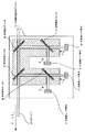
図1(a)、(b)は本発明に係る光送信モジュールの第1の実施の形態の概略構成を部分的に断面で示した平面図及びその側面図である。図1(a)において、光送信モジュール9は、ベース部8に固定された半導体レーザ素子4及び光結合部7とを備えている。光結合部7はガラスなどからなり、第1の光ファイバ1、第2の光ファイバ2、第3の光ファイバ3をそれぞれ埋め込む穴及び反射型光フィルタ5を挿着するためのスリット6が形成されている。この場合、スリット6は直線状に貫通するファイバ埋め込み用の穴と交差するようにして斜めに切り欠かれ、ここに反射型光フィルタ5が装着されている。反射型光フィルタ5はポリイミドなどの薄膜に蒸着が施された厚さの薄いもので構成され、この反射型光フィルタ5の中心部を境にして、第2の光ファイバ2の光入射端及び第3の光ファイバ3の光出射端が光軸を一致させて結合され、その光軸に対して第1の光ファイバ1の光出射端が略直角に結合されている。第1の光ファイバ1の光入射端に半導体レーザ素子4が結合されている。なお、反射型光フィルタ5は、ある中心波長を持つ光信号(波長=λ1)を反射させる一方、この光信号以外の中心波長を持つ光信号(波長≠λ1)を透過する特性のものが用いられている。以下、中心波長が例えばλ1の波長帯域を有する光信号を、単に波長λ1の光信号と略記する場合もある。
【0027】
次に、光送信モジュールの第1の実施の形態の動作について説明する。半導体レーザ素子4により光信号が生成され、第1の光ファイバ1に入射される。半導体レーザ素子4から出力される光信号の波長をλ1とすると、反射型光フィルタ5は、λ1を含む一定の波長範囲の光信号を反射し、それ以外の波長λ2の光信号を透過させる。したがって、半導体レーザ素子4から出射された波長λ1の光信号は、反射型光フィルタ5で反射され、第2の光ファイバ2に入射される。一方、光送信モジュール9に外部から入射される信号は、その波長をλ2とすると、第3の光ファイバ3、反射型光フィルタ5により第2の光ファイバ2に入射され、半導体レーザ素子4から出射される光信号と波長多重される。
【0028】
このように、光送信モジュールの第1の実施の形態によれば、スリットに埋め込まれた反射型光フィルタにより、送信用の光信号と外部から入射された光信号を多重し、また、ファイバとの結合をファイバ埋め込み用貫通穴に光ファイバを実装し、光ファイバ間に挿入する反射型光フィルタをポリイミドなどの薄膜に蒸着が施された厚さの薄い光フィルタを用いて、光ファイバ間を近接させて実装することで光のビーム径の広がりを抑圧し、損失を低減させることができるほか、モジュール規模を小さくすることができる。また、光学レンズを用いないため低コスト化が可能となる。
【0029】
<光送信モジュールの第2の実施の形態>
図2は本発明に係る光送信モジュールの第2の実施の形態の構成を部分的に断面で示した平面図である。図中、図1と同一の要素には同一の符号を付してその説明を省略する。第1の実施の形態が反射型光フィルタ5を用いたのに対して、第2の実施の形態に係る光送信モジュール11は透過型光フィルタ10を用いた点が相違している。この相違に伴って、半導体レーザ素子4が接続される第1の光ファイバ1の延長上に第2の光ファイバ2が装着されるように光結合部7に貫通穴が形成され、この貫通穴に対して直交する方向に第3の光ファイバ3を装着するための穴が形成されている。なお、透過型光フィルタ10は、ある中心波長を持つ光信号(波長=λ1)を透過させる一方、この光信号以外の中心波長を持つ光信号(波長≠λ1)を反射する性質のものが用いられている。
【0030】
次に、光送信モジュールの第2の実施の形態の動作について説明する。半導体レーザ素子4により光信号が生成され、第1の光ファイバ1に入射される。この半導体レーザ素子4から出力される光信号の波長をλ1とすると、透過型光フィルタ10は、λ1を含む一定の波長範囲を透過させ、それ以外の波長λ2を反射させる。よって半導体レーザ素子4から出射された光信号は、透過型光フィルタ10を透過し、第2の光ファイバ2に結合される。一方、光送信モジュール11に外部から入射される信号は、その波長をλ2とすると第3の光ファイバ3、透過型光フィルタ10により第2の光ファイバ2に結合され、半導体レーザ素子4から出射される光信号と波長多重される。
【0031】
このように、光送信モジュールの第2の実施の形態によれば、スリットに埋め込んだ透過型光フィルタにより、送信用の光信号と外部から入射された光信号を多重し、また、光ファイバとの結合をファイバ埋め込み用貫通穴に光ファイバを実装し、光ファイバ間に挿入する透過型光フィルタをポリイミドなどに薄膜が蒸着が施された厚さの薄い光フィルタを用いて、光ファイバ間を近接させて実装することで光のビーム径の広がりを抑圧し、損失を低減させることができるほか、モジュール規模を小さくできる。また、光学レンズを用いないため低コスト化が可能となる。
【0032】
<多波長光送信モジュールの第1の実施の形態>
図3は本発明に係る多波長光送信モジュールの第1の実施の形態の概略構成を部分的に断面で示した平面図である。この実施の形態は、図1に示したものと同一構成の光送信モジュール14及び光送信モジュール17を縦列接続したものである。このうち、光送信モジュール14は半導体レーザ素子12、反射型光フィルタ13及び光ファイバ18を含み、光送信モジュール17は半導体レーザ素子15、反射型光フィルタ16、光ファイバ19、20を含み、光ファイバ19が光送信モジュール17の光信号出力経路を形成するとともに、光送信モジュール14の光信号入力経路を形成している。
【0033】
上記のように構成された多波長光送信モジュールの第1の実施の形態の動作について、図4をも参照して以下に説明する。
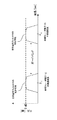
各光送信モジュール14、17の半導体レーザ素子12、15からそれぞれ出射された中心波長がλ1、λ2の光信号は、図4に示すような各光送信モジュール14、17が有する反射特性の異なる反射型光フィルタ13、16により光ファイバ20から入射される波長λ3〜λnと波長多重され、光ファイバ18からは、λ1〜λnの多重信号が出力される。
【0034】
このように、多波長光送信モジュールの第1の実施の形態によれば、光結合部のスリット6A、6Bにそれぞれ埋め込んだ反射型光フィルタ13、16により、半導体レーザ素子12、15、及び光ファイバ20から出射される光信号を波長多重し、また、ファイバ埋め込み用貫通穴に光ファイバ18〜20を実装し、ファイバ間に挿入する反射型光フィルタ13、16をポリイミドなどの薄膜に蒸着が施された厚さの薄い光フィルタを用いて、光ファイバ18〜20間を近接させて実装することによって光のビーム径の広がりを抑圧し、損失を低減させることができるほか、モジュール規模を小さくすることができる。また、光学レンズを用いないため低コストな多波長対応の光送信モジュールを実現することが可能となる。
【0035】
<多波長光送信モジュールの第2の実施の形態>
図5は本発明に係る多波長光送信モジュールの第2の実施の形態の概略構成を部分的に断面で示した平面図である。図中、図3と同一の要素には同一の符号を付してその説明を省略する。前述したように、図3に示した第1の実施の形態では光送信モジュール間が光ファイバで多段接続されていたのに対して、図5に示す第2の実施の形態では、光送信モジュール14及び光送信モジュール17が光導波路ブロック23上に離隔して装着され、光送信モジュール14、17間をPLC(Planer Lightwave Circuit)のような光導波路21で接続し、さらに、光送信モジュール17の光信号入力経路を光導波路22で形成している。
【0036】
上記のように構成された多波長光送信モジュールの第2の実施の形態の動作について以下に説明する。各光送信モジュール14、17の半導体レーザ素子12、15から出射される光信号は、図4に示すような各光送信モジュール14、17が有する反射特性の異なる反射型光フィルタ13、16により波長多重され、光送信モジュール14、17間を光導波路21で結合することで、光ファイバ24から、波長がλ1〜λnの多重信号が出力される。
【0037】
このように、多波長光送信モジュールの第2の実施の形態によれば、光結合部のスリットに埋め込んだ反射型光フィルタ13、16により、各半導体レーザ素子12、15から出射される中心波長がλ1、λ2の光信号が光導波路22から入射される波長λ3〜λnの光信号と波長多重され、光ファイバ24からは、λ1〜λnの多重信号が出力される。この場合、反射型光フィルタ13、16をポリイミドなどの薄膜に蒸着が施された厚さの薄い光フィルタを用いて、光ファイバ間を近接させて実装することにより光のビーム径の広がりを抑圧し、損失を低減させることができるほか、モジュール規模を小さくすることができる。さらに、光送信モジュール間を光導波路で接続することにより、光ファイバの余長処理などが不要となり、モジュールをより小さくすることができる。また、光学レンズを用いないため低コストな多波長対応の光送信モジュールを実現することが可能となる。
【0038】
<多波長光送信モジュールの第3の実施の形態>
図6は本発明に係る多波長光送信モジュールの第3の実施の形態の概略構成を部分的に断面で示した平面図である。図中、図3と同一の要素には同一の符号を付してその説明を省略する。この実施の形態は図3を用いて説明した多波長光送信モジュールの第1の実施の形態の光送信モジュール14、17の各光結合部を単一の光結合部で一体化して一体型光送信モジュール25を形成し、これに出力用の光ファイバ26を結合したものである。
【0039】
上記のように構成された多波長光送信モジュールの第3の実施の形態の動作について以下に説明する。各光送信モジュールの半導体レーザ素子12、15から出射される波長がそれぞれλ1、λ2の光信号は、反射特性の異なる反射型光フィルタ13、16により外部から入射される波長λ3〜λnと波長多重され、光ファイバ26からは、波長λ1〜λnの多重信号が出力される。
【0040】
このように、多波長光送信モジュールの第3の実施の形態によれば、単一の光結合部の2つのスリットにそれぞれ埋め込んだ反射型光フィルタにより、半導体レーザ素子12、15から出射される光信号を波長多重し、また、ファイバ埋め込み用貫通穴に光ファイバを実装し、光ファイバ間に挿入する反射型光フィルタをポリイミドなどの薄膜に蒸着が施された厚さの薄い光フィルタを用いて、光ファイバ間を近接して実装することにより光のビーム径の広がりを抑圧し、損失を低減させることができるほか、モジュール規模を小さくすることができる。さらに、各反射型光フィルタを1つの光結合部に一体化することによってモジュールをより小さくすることができる。また、光学レンズを用いないため、低コストな多波長対応の光送信モジュールを実現することが可能となる。
【0041】
<多波長光送信モジュールの第3の実施の形態の変形例>
図7は本発明に係る多波長光送信モジュールの第3の実施の形態の変形例であり、特に、反射型光フィルタ13、16の反射特性を示したものである。この変形例においては、各反射型光フィルタ13、16の中心波長にガードバンドを設けたものである。このようにガードバンドを設けることによって、各半導体レーザ素子12、15が異常をきたし、波長がずれたとしても、波長が隣接するチャネルに影響を及ぼすことを低減させることができる。
このように、多波長光送信モジュールの第3の実施の形態の変形例によれば、第1から第3の実施の形態の効果に加えて、各反射型光フィルタ13、16の中心波長にガードバンドを設けることにより、半導体レーザ素子12、15が異常をきたし、波長が大きくずれたとしても、隣接する波長のチャネルに影響を及ぼすことを低減させることができるという効果も得られる。
【0042】
<多波長光送信モジュールの第4の実施の形態>
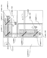
図8は本発明に係る多波長光送信モジュールの第4の実施の形態の部分断面図である。この実施の形態は反射型光フィルタ29によって波長λ1の光信号と波長λ2(>λ1)の光信号とを光多重し、さらに、反射型光フィルタ30を用いて波長λがλ2より大きな光信号を光多重して光ファイバ37より出力する光送信モジュール35と、反射型光フィルタ33によって波長λ3(>λ2)の光信号と波長λ4(>λ3)の光信号とを光多重し、さらに、反射型光フィルタ34を用いて波長λがλ4より大きな光信号を光多重して光ファイバ38より出力する光送信モジュール36とを備え、光ファイバ38を光送信モジュール35の信号入力経路として結合し、光送信モジュール36の外部信号入力経路として光ファイバ39を結合し、波長λ5〜λnの光多重信号を入力する構成になっている。
【0043】
上記のように構成された多波長光送信モジュールの第4の実施の形態の動作について図9をも参照して以下に説明する。反射型光フィルタ29は半導体レーザ素子27が出射する波長λ1を中心波長とする光信号を反射し、反射型光フィルタ30は波長λ1だけでなく波長λ2を中心波長とする連続する波長領域の光信号をも反射する特性を有している。また、反射型光フィルタ33は半導体レーザ素子31が出射する波長λ3を中心波長とする光信号を反射し、反射型光フィルタ34は波長λ3だけでなく波長λ4を中心波長とする連続する波長領域の光信号をも反射する特性を有している。
【0044】
そこで、光送信モジュール35の半導体レーザ素子27、28からそれぞれ出射される光信号のうち、波長λ1の光信号が反射型光フィルタ29で反射し、波長λ2の光信号が反射型光フィルタ29を透過して波長λ1、λ2の多重化光信号が反射型光フィルタ30によって反射して光ファイバ37に向かう。一方、光送信モジュール36の半導体レーザ素子31、32からそれぞれ出射される光信号のうち、波長λ3の光信号が反射型光フィルタ33で反射し、波長λ4の光信号が反射型光フィルタ33を透過して波長λ3、λ4の多重化光信号が反射型光フィルタ34によって反射して光ファイバ38に向かう。また、光ファイバ39を介して、入力される波長λ5〜λnの光信号は反射型光フィルタ34を透過し、光ファイバ38に向かう。したがって、光ファイバ38を通過する波長λ3〜λnの多重化光信号は反射型光フィルタ30を通過して光ファイバ37へ向かう。この結果、光ファイバ37から波長λ1〜λnの多重信号が出力される。よって、波長の異なる一方の信号を反射し、他方の信号を透過する反射型光フィルタと、これら2つの波長の光信号を反射し、より波長の大きい光信号を透過する反射型光フィルタを有する光送信モジュールを多段に接続することにより、多波長信号を多重する光送信モジュールを構成することができる。
【0045】
図3に示す多波長光送信モジュールの第1の実施の形態のように、反射型光フィルタでそれぞれ1波長ずつを合波するのではなく、多重/分離する波長数を2波長にすることにより、例えば8波長の多重を考えた場合、多波長光送信モジュールの第1の実施の形態では最大7個の光フィルタを通過する波長が存在するのに対して、本実施の形態のように2波長分離する構成では、最大5個の光フィルタの通過で済み、光フィルタ通過にともなう損失を低減させることができる。ここでは、2波長を分離する光フィルタで説明したが、これを3波長以上にすれば、更に最大通過光フィルタ数を低減することができ、損失を低減させることができる。
【0046】
このように、多波長光送信モジュールの第4の実施の形態によれば、光結合部に形成したスリットに埋め込んだ反射型光フィルタにより、各半導体レーザ素子から出射される光信号を波長多重し、また、ファイバ埋め込み用貫通穴に光ファイバを実装し、光ファイバ間に挿入する反射型光フィルタをポリイミドなどの薄膜に蒸着が施された厚さの薄い光フィルタを用いて、光ファイバ間を近接させて実装することで光のビーム径の広がりを抑圧し、損失を低減させることができるほか、モジュール規模を小さくすることができる。さらに、光学レンズを用いないため低コストな多波長対応の光送信モジュールが実現可能となるほか、多重分離する波長数を2波長以上となる光フィルタを組み合わせて、各波長が光フィルタを通過する回数を低減させることにより、光フィルタ通過に伴う挿入損失を低減することができる。
【0047】
<多波長光送信モジュールの第5の実施の形態>
図10は本発明に係る多波長光送信モジュールの第5の実施の形態の構成を部分的に断面で示した平面図である。図中、図8と同一の要素には同一の符号を付してその説明を省略する。図8に示す多波長光送信モジュールの第4の実施の形態では、光送信モジュール35、36間が光ファイバ38で多段接続されていたが、図10に示した第5の実施の形態は、各光送信モジュール35、36を光導波路ブロック42に装着し、この光導波路ブロック42上に形成した光送信モジュール35、36間をPLCのような光導波路40で接続し、さらに、光送信モジュール36の光信号入力経路をも光導波路41とし、光送信モジュール35の出力経路に光ファイバ43を結合した構成になっている。
この第5の実施の形態は光送信モジュール35、36間の接続が光ファイバから光導波路40に変更されただけであるため、その動作説明を省略する。
【0048】
このように、図10に示す多波長光送信モジュールの第5の実施の形態によれば、光結合部に形成したスリットに埋め込んだ反射型光フィルタにより、各半導体レーザ素子から出射される光信号を波長多重し、また、ファイバ埋め込み用貫通穴に光ファイバを実装し、ファイバ間に挿入する反射型光フィルタをポリイミドなどの薄膜に蒸着が施された厚さの薄い光フィルタを用いて、光ファイバ間を近接させて実装することで光のビーム径の広がりを抑圧し、損失を低減させることができるほか、モジュール規模を小さくできる。さらに光送信モジュール間を光導波路で接続することにより、光ファイバの余長処理などが不要となり、モジュールをより小さくすることができる。また、光学レンズを用いないため低コストな多波長対応の光送信モジュールが実現可能となるほか、多重分離する波長数を2波長以上となる光フィルタを組み合わせ、各波長が光フィルタを通過する回数を低減することにより、光フィルタ通過に伴う挿入損失を低減させることができる。
【0049】
<多波長光送信モジュールの第6の実施の形態>
図11は本発明に係る多波長光送信モジュールの第6の実施の形態の構成を部分的に断面で示した平面図である。図中、図10と同一の要素には同一の符号を付してその説明を省略する。この実施の形態は図10に示す光送信モジュール35、36を単一の光結合部により一体型光送信モジュール44を構成したもので、光出力経路に光ファイバ45を結合したものである。この実施の形態は図10を用いて説明した多波長光送信モジュールの第5の実施の形態と同一であるので、その動作説明を省略する。
【0050】
このように、図11に示す多波長光送信モジュールの第6の実施の形態によれば、スリットに埋め込んだ反射型光フィルタにより、各半導体レーザ素子から出射される光信号と外部から入射される光信号を波長多重し、また、ファイバ埋め込み用貫通穴に光ファイバを実装し、光ファイバ間に挿入する反射型光フィルタをポリイミドなどの薄膜に蒸着が施された厚さの薄い光フィルタを用いて、光ファイバ同士を近接させて実装することで光のビーム径の広がりを抑圧し、損失を低減させることができるほか、モジュール規模を小さくすることができる。さらに、各反射型光フィルタを1つのガラスブロックに一体化することでモジュールをより小さくすることができる。また、光学レンズを用いないため低コストな多波長対応の光送信モジュールを実現することが可能となるほか、多重分離する波長数が2波長以上となる光フィルタを組み合わせ、各波長が光フィルタを通過する回数を低減することにより、光フィルタ通過に伴う挿入損失を低減させることができる。
【0051】
<多波長光送信モジュールの第7の実施の形態>
図12は本発明に係る多波長光送信モジュールの第7の実施の形態の構成を部分的に断面で示した平面図である。この実施の形態は、波長λ1の光信号を発生する半導体レーザ素子12及び透過型光フィルタ46を含み、光信号出力経路に光ファイバ50が接続されている光送信モジュール47と、波長λ2の光信号を発生する半導体レーザ素子15及び透過型光フィルタ48を含み、光信号出力経路が光ファイバ51によって光送信モジュール47に接続され、波長がλ3〜λnの光信号を入力する入力経路に光ファイバ52が接続された光送信モジュール49とで構成されている。
【0052】
上記のように構成された多波長光送信モジュールの第7の実施の形態の動作について図13をも参照して以下に説明する。光送信モジュール47、49の各半導体レーザ素子12、15から出射される光信号は、図13に示すように、中心波長がλ1、λ2で、透過領域が互いに隣接する透過特性を有する透過型光フィルタ48、46により波長多重され、光ファイバ50からは、λ1〜λnの多重信号が出力される。
【0053】
このように、図12に示す多波長光送信モジュールの第7の実施の形態によれば、スリットに埋め込んだ透過型光フィルタにより、各半導体レーザ素子から出射される光信号と外部から入射される光信号とを波長多重し、また、ファイバ埋め込み用貫通穴に光ファイバを実装し、光ファイバ間に挿入する透過型光フィルタをポリイミドなどの薄膜に蒸着が施された厚さの薄い光フィルタを用いて、光ファイバ間を近接させて実装することにより光のビーム径の広がりを抑圧し、損失を低減させることができるほか、モジュール規模を小さくすることができる。また、光学レンズを用いないため低コストな多波長対応の光送信モジュールを実現することが可能となる。
【0054】
<多波長光送信モジュールの第8の実施の形態>
図14は本発明に係る多波長光送信モジュールの第8の実施の形態の構成を部分的に断面で示した平面図である。図中、図12と同一の要素には同一の符号を付してその説明を省略する。この実施の形態は、図12に示した光送信モジュール47、49を単一の光導波路ブロック55上に装着し、光送信モジュール47、49を、光導波路ブロック55上に形成したPLCのような光導波路53で結合し、さらに、光送信モジュール49に対する外部からの光信号経路を光導波路54で構成し、光送信モジュール47の出力信号経路に光ファイバ56を結合したものである。
【0055】
次に、動作について説明する。各光送信モジュール47、49の半導体レーザ素子12、15から出射される光信号は、図13に示すような各光送信モジュールが有する透過特性の異なる透過型光フィルタ46、48により波長多重され、光送信モジュール47、49間を光導波路53で結合することによって、光ファイバ56からは、λ1〜λnの多重信号が出力される。
【0056】
このように、図14に示す多波長光送信モジュールの第8の実施の形態によれば、スリットに埋め込んだ透過型光フィルタ46、48により、各半導体レーザ素子12、15及び光導波路54から出射される光信号を波長多重し、また、ファイバ埋め込み用貫通穴に光ファイバ56を実装し、光ファイバ間に挿入する透過型光フィルタをポリイミドなどの薄膜に蒸着が施された厚さの薄い光フィルタを用いて、光ファイバ間を近接させて実装することで光のビーム径の広がりを抑圧し、損失を低減させることができるほか、モジュール規模を小さくできる。さらに光送信モジュール間を光導波路で接続することにより、光ファイバの余長処理などが不要となり、光送信モジュールをより小さくすることができる。また、光学レンズを用いないため低コストな多波長対応の光送信モジュールが実現可能となる。
【0057】
<多波長光送信モジュールの第9の実施の形態>
図15は本発明に係る多波長光送信モジュールの第9の実施の形態の構成を部分的に断面で示した平面図である。図6に示す多波長光送信モジュールの第3の実施の形態が反射型光フィルタ13、16を用いて波長を多重/分離しているのに対して、図15に示す第9の実施の形態は透過型光フィルタ46、48を単一の光結合部の2つのスリットに装着して、波長を多重/分離するように構成したものである。ここで、半導体レーザ素子12が出射する中心波長がλ1の光信号に対するファイバ埋め込み用貫通穴と交差するように形成されたスリットに透過型光フィルタ46が挿着され、この透過型光フィルタ46の一方に半導体レーザ素子12の出射光を入力する光ファイバ58が埋め込まれ、この透過型光フィルタ46の光信号出力側に光ファイバ58の一端部が埋め込まれている。また、半導体レーザ素子15が出射する中心波長がλ2の光信号に対するファイバ埋め込み穴が、中心波長がλ1の光信号に対するファイバ埋め込み用貫通穴と直交する方向に形成され、この穴と交差するように形成されたスリットに透過型光フィルタ48が挿着され、この透過型光フィルタ48の一方に半導体レーザ素子15の出射光を入力する光ファイバが埋め込まれ、この透過型光フィルタ48の光信号出力側に光信号出力用の光ファイバ58Aが埋め込まれている。さらに、中心波長がλ2の光信号のためのファイバ埋め込み用の穴と直交する方向に、外部から波長がλ3〜λnの光信号を入力するための光ファイバ58Bが埋め込まれている。
【0058】
上記のように構成された多波長光送信モジュールの第9の実施の形態の動作について説明する。透過型光フィルタ46、48は、図13に示すように、中心波長がλ1、λ2で、透過領域が互いに隣接する透過特性を有している。したがって、半導体レーザ素子12から出射される波長λ1の光信号は透過型光フィルタ46を透過して光ファイバ58からそのまま出力される。また、半導体レーザ素子15から出射される波長λ2の光信号は透過型光フィルタ48を通過し、透過型光フィルタ46で反射されて光ファイバ58から出力される。一方、外部から入射された波長λ3〜λnの光信号は透過型光フィルタ48で反射され、さらに、透過型光フィルタ46で反射されて光ファイバ58から出力される。よって、半導体レーザ素子12、15から出射される送信用光信号は透過型光フィルタ46、48により波長λ3〜λnの光信号と多重化され、光ファイバ58からはλ1〜λnの多重信号が出力される。
【0059】
このように、図15に示す第9の実施の形態によれば、光結合部の2つのスリットにそれぞれ埋め込んだ透過型光フィルタ46、48により、半導体レーザ素子12、15から出射される光信号を波長多重し、また、ファイバ埋め込み用貫通穴に光ファイバを実装し、光ファイバ間に挿入する透過型光フィルタをポリイミドなどの薄膜に蒸着が施された厚さの薄い光フィルタを用いて、光ファイバ間を近接させて実装することで光のビーム径の広がりを抑圧し、損失を低減させることができるほか、モジュール規模を小さくできる。さらに、各透過型光フィルタを1つのガラスブロックに一体化することでモジュールをより小さくすることができる。光学レンズを用いないため低コストな多波長対応の光送信モジュールが実現可能となる。
【0060】
<多波長光送信モジュールの第9の実施の形態の変形例>
図16は本発明に係る多波長光送信モジュールの第9の実施の形態の変形例であり、特に、透過型光フィルタ46、48の透過特性を示したものである。この変形例においては、各透過型光フィルタ46、48の中心波長にガードバンドを設けたものである。このようにガードバンドを設けることによって、各半導体レーザ素子12、15が異常をきたし、波長が大きくずれたとしても、波長が隣接するチャネルに影響を及ぼすことを低減させることができるという効果も得られる。
【0061】
<多波長光送信モジュールの第10の実施の形態>
図17は本発明に係る多波長光送信モジュールの第10の実施の形態の構成を部分的に断面で示した平面図である。この実施の形態は、波長がλ1からλnまでの各光信号を多重して出力する光ファイバ65を有する光送信モジュール63と、外部から波長がλ5〜λnの光信号を、光ファイバ67を介して入力する光送信モジュール64とを光ファイバ66で結合したものである。このうち、光送信モジュール63は、半導体レーザ素子27、28と、半導体レーザ素子27から出射される波長λ1の光信号を通過させ、半導体レーザ素子28から出射される波長λ2の光信号を反射させる透過型光フィルタ59と、波長λ1及びλ2の光信号を透過させ、波長λ3〜λnの光信号を反射させる透過型光フィルタ60とを備えている。一方、光送信モジュール64は、半導体レーザ素子31、32と、半導体レーザ素子32から出射される波長λ3の光信号を通過させ、半導体レーザ素子31から出射される波長λ4の光信号を反射させる透過型光フィルタ61と、波長λ3及びλ4の光信号を透過させ、波長λ5〜λnの光信号を反射させる透過型光フィルタ62とを備えている。
【0062】
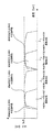
上記のように構成された多波長光送信モジュールの第10の実施の形態の動作について、図18をも参照して、以下に説明する。図18に示すように、透過型光フィルタ59は半導体レーザ素子27が出射する波長λ1を中心波長とする光信号を透過し、透過型光フィルタ60は波長λ1だけでなく波長λ2を中心波長とする連続する波長領域の光信号を透過する特性を有している。また、透過型光フィルタ61は半導体レーザ素子32が出射する波長λ3を中心波長とする光信号を透過し、透過型光フィルタ62は波長λ3だけでなく波長λ4を中心波長とする連続する波長領域の光信号を透過する特性を有している。
【0063】
そこで、光送信モジュール63を構成する透過型光フィルタ59において、半導体レーザ素子27から出射された波長λ1の光信号は透過し、半導体レーザ素子28から出射された波長λ2の光信号は反射される。また、光送信モジュール63を構成する透過型光フィルタ60において、波長λ1及びλ2の光信号は透過し、これ以外の波長の光信号は反射される。一方、光送信モジュール64を構成する透過型光フィルタ61において、半導体レーザ素子32から出射された波長λ3の光信号は透過し、半導体レーザ素子31から出射された波長λ4の光信号は反射する。また、光送信モジュール64を構成する透過型光フィルタ62において、波長λ3及びλ4の光信号は透過し、これ以外の波長の光信号は反射される。このように、それぞれ1段目の透過型光フィルタ59、61で1波長の光信号を透過し、2段目の透過型光フィルタ60、62で2波長分の光信号を透過する光送信モジュール63、64を光ファイバ66で接続することにより、多波長信号を多重する光送信モジュールを構成することができる。
【0064】
このように、図12に示す多波長光送信モジュールの第7の実施の形態のように、各透過型光フィルタで1波長ずつを合波するのではなく、多重/分離する波長数を2波長にすることにより、例えば8波長の多重を考えた場合、第7の実施の形態では最大7個の光フィルタを通過する波長が存在するのに対して、第10の実施の形態のように2波長分離する構成では、最大5個の光フィルタの通過で済み、光フィルタ通過に伴う損失を低減させることができる。今回は2波長を分離する光フィルタで説明したが、これを3波長以上にすれば、更に最大通過光フィルタ数を低減することができ、損失を低減させることができる。
【0065】
このように、図17に示す多波長光送信モジュールの第10の実施の形態によれば、それぞれ光結合部に形成した2箇所のスリットに埋め込んだ透過型光フィルタにより、各半導体レーザ素子及び光ファイバから出射される光信号を波長多重し、また、ファイバ埋め込み用貫通穴に光ファイバを実装し、光ファイバ間に挿入する透過型光フィルタをポリイミドなどの薄膜に蒸着が施された厚さの薄い光フィルタを用いて、光ファイバ間を近接させて実装することで光のビーム径の広がりを抑圧し、損失を低減させることができるほか、モジュール規模を小さくすることができる。さらに、光学レンズを用いないため低コストな多波長対応の光送信モジュールが実現可能となるほか、多重分離する波長数を2波長以上となる光フィルタを組み合わせ、各波長が光フィルタを通過する回数を低減することにより、光フィルタ通過に伴う挿入損失を低減させることができる。
【0066】
<多波長光送信モジュールの第11の実施の形態>
図19は本発明に係る多波長光送信モジュールの第11の実施の形態の構成を部分的に断面で示した平面図である。ここに示した多波長光送信モジュールは、図17に示す多波長光送信モジュールを構成する光送信モジュール63及び64を単一の光導波路ブロック70上に装着し、光送信モジュール63及び64の光結合経路、並びに、光送信モジュール64に対する波長λ5〜λnの多波長光入射経路を、それぞれ光導波路ブロック70上に形成したPLCのような光導波路68で接続し、かつ図17の入射用の光ファイバ67を光導波路69に置換したものである。これ以外は図17に示す多波長光送信モジュールの第10の実施の形態と同様に構成されている。
図19に示す多波長光送信モジュールの第11の実施の形態の動作については、図17に示す第10の実施の形態と同じであるので説明を省略するが、光送信モジュール63及び64を光導波路68で接続したことにより、光ファイバの余長処理などが不要となる。
【0067】
このように、図19に示す多波長光送信モジュールの第11の実施の形態によれば、スリットに埋め込んだ透過型光フィルタにより、各半導体レーザ素子及び光導波路から出射される光信号を波長多重し、また、ファイバ埋め込み用貫通穴に光ファイバを実装し、光ファイバ間に挿入する透過型光フィルタをポリイミドなどの薄膜に蒸着が施された厚さの薄い光フィルタを用いて、光ファイバ間を近接させて実装することで光のビーム径の広がりを抑圧し、損失を低減させることができるほか、モジュール規模を小さくできる。さらに光送信モジュール間を光導波路で接続することにより、光ファイバの余長処理などが不要となり、モジュールをより小さくすることができる。また、光学レンズを用いないため低コストな多波長対応の光送信モジュールが実現可能となるほか、多重分離する波長数を2波長以上となる光フィルタを組み合わせ、各波長が光フィルタを通過する回数を低減することにより、光フィルタ通過に伴う挿入損失を低減させることができる。
【0068】
<多波長光送信モジュールの第12の実施の形態>
図20は本発明に係る多波長光送信モジュールの第12の実施の形態の構成を部分的に断面で示した平面図である。ここに示した多波長光送信モジュールは、図19に示す光送信モジュール63及び64を単一の光結合部で一体化した点が図19に示した多波長光送信モジュールの第11の実施の形態と異なるだけで、これ以外は第11の実施の形態と同一に構成されている。
図20に示す多波長光送信モジュールの第12の実施の形態の動作については、図19に示す第11の実施の形態と同じであるので説明を省略するが、各透過型光フィルタ59〜62を1つのガラスブロックに一体化することでモジュールをより小さくすることができる。
【0069】
このように、図20に示す多波長光送信モジュールの第12の実施の形態によれば、スリットに埋め込んだ透過型光フィルタにより、半導体レーザ素子及び光導波路から出射される光信号を波長多重し、また、ファイバ埋め込み用貫通穴に光ファイバを実装し、光ファイバ間に挿入する透過型光フィルタをポリイミドなどの薄膜に蒸着が施された厚さの薄い光フィルタを用いて、光ファイバ間を近接させて実装することで光のビーム径の広がりを抑圧し、損失を低減させることができるほか、モジュール規模を小さくできる。さらに、各透過型光フィルタを1つのガラスブロックに一体化することでモジュールをより小さくすることができる。また、光学レンズを用いないため低コストな多波長対応の光送信モジュールが実現可能となるほか、多重分離する波長数を2波長以上となる光フィルタを組み合わせ、各波長が光フィルタを通過する回数を低減することにより、光フィルタ通過に伴う挿入損失を低減させることができる。
【0070】
なお、上記の各実施の形態では、波長多重について説明したが、これを波長分離部とすることができ、この場合には波長分離特性に優れた光送信モジュール及び多波長光送信モジュールとすることができる。
なおまた、上記の各実施の形態では、ポリイミドなどの薄膜に蒸着を施して、反射型光フィルタや透過型フィルタを形成したが、蒸着に限らず集積回路の形成などに用いられる他の成膜技術を応用して作成してもよい。
【0071】
【発明の効果】
以上の説明によって明らかなように、本発明によれば、薄膜材料上に成膜された厚さの薄い光フィルタを用いて、光ファイバ間を近接させて実装することで光のビーム径の広がりを抑圧し、損失を低減させることができるほか、モジュール規模を小さくでき、さらに、光学レンズを用いないため低コスト化が可能となる。また、光のビーム径の広がりを抑圧するため、波長分離に用いたときの波長分離特性を向上させることができる。
【図面の簡単な説明】
【図1】本発明に係る光送信モジュールの第1の実施の形態の構成を部分的に断面で示した平面図及びその側面図
【図2】本発明に係る光送信モジュールの第2の実施の形態の構成を部分的に断面で示した平面図
【図3】本発明に係る多波長光送信モジュールの第1の実施の形態の構成を部分的に断面で示した平面図
【図4】図3に示した多波長光送信モジュールの第1の実施の形態を構成する反射型光フィルタの反射特性の一例を示す図
【図5】本発明に係る多波長光送信モジュールの第2の実施の形態の構成を部分的に断面で示した平面図
【図6】本発明に係る多波長光送信モジュールの第3の実施の形態の構成を部分的に断面で示した平面図
【図7】図6に示す多波長光送信モジュールの第3の実施の形態の変形例を構成する要素である、反射型光フィルタの反射特性の一例を示す図
【図8】本発明に係る多波長光送信モジュールの第4の実施の形態の構成を部分的に断面で示した平面図
【図9】図8に示した多波長光送信モジュールの第4の実施の形態を構成する反射型光フィルタの反射特性の一例を示す図
【図10】本発明に係る多波長光送信モジュールの第5の実施の形態の構成を部分的に断面で示した平面図
【図11】本発明に係る多波長光送信モジュールの第6の実施の形態の構成を部分的に断面で示した平面図
【図12】本発明に係る多波長光送信モジュールの第7の実施の形態の構成を部分的に断面で示した平面図
【図13】図12に示した多波長光送信モジュールの第7の実施の形態を構成する透過型光フィルタの透過特性の一例を示す図
【図14】本発明に係る多波長光送信モジュールの第8の実施の形態の構成を部分的に断面で示した平面図
【図15】本発明に係る多波長光送信モジュールの第9の実施の形態の構成を部分的に断面で示した平面図
【図16】図15に示す多波長光送信モジュールの第9の実施の形態の変形例を構成する要素である、透過型光フィルタの透過特性の一例を示す図
【図17】本発明に係る多波長光送信モジュールの第10の実施の形態の構成を部分的に断面で示した平面図
【図18】図17に示す多波長光送信モジュールの第10の実施の形態を構成する要素である透過型光フィルタの透過特性の一例を示す図
【図19】本発明に係る多波長光送信モジュールの第11の実施の形態の構成を部分的に断面で示した平面図
【図20】本発明に係る多波長光送信モジュールの第12の実施の形態の構成を部分的に断面で示した平面図
【図21】従来の多波長光送信モジュールの構成を示す図
【符号の説明】
1 第1の光ファイバ
2 第2の光ファイバ
3 第3の光ファイバ
4、12、15、27、28、31、32、74〜77 半導体レーザ素子
5、13、16、29、30、33、34 反射型光フィルタ
6、6A、6B スリット
7 光結合部
8 ベース部
9、11、14、17、35、36、47、49、63、64 光送信モジュール
10、46、48、59〜62 透過型光フィルタ
18〜20、24、26、37〜39、43、45、50〜52、56、58、65〜67、71、73、78〜81、94〜97 光ファイバ
21、22、40、41、53、54、68、69 光導波路
23、42、55、70 光導波路ブロック
25、44、57、72 一体型光送信モジュール
82〜89 コリメートレンズ
90〜93 光フィルタ[0001]
TECHNICAL FIELD OF THE INVENTION
The present invention relates to an optical transmission module and a multi-wavelength optical transmission module having a wavelength multiplexing function of a multi-wavelength wavelength multiplexed signal in optical communication.
[0002]
[Prior art]
In optical communication, a wavelength division multiplexing transmission technique has been widely used. In this method, a plurality of signal lights having different wavelengths are multiplexed into one, transmitted using an optical fiber, and each signal light is demultiplexed for each wavelength at a transmission end. For wavelength multiplexing / demultiplexing, a diffraction grating type multiplexer / demultiplexer, a dielectric multilayer filter, or the like is used (see
[0003]
[Patent Document 1]
JP-A-9-213383 (FIG. 1, paragraphs 0032 to 0044)
[0004]
In a diffraction grating type multiplexer / demultiplexer, by applying multiplexed signal light to a diffraction grating, signal light of each wavelength can be emitted and demultiplexed at different angles. Conversely, if signal light of each wavelength is incident from the emission direction of this diffraction grating, it functions as a multiplexer. This diffraction grating type multiplexer / demultiplexer has a feature that the structure is simple and the loss of each port is almost constant, and is advantageous when the number of wavelengths is 10 or more, but the cost is high. Therefore, when the wavelength is 10 waves or less, the cost per port increases.
[0005]
Since the dielectric multilayer filter has the function of a bandpass filter, light having a wavelength that does not satisfy the transmission conditions and reflection conditions in each film is extracted as reflected light or transmitted light, and demultiplexed. However, this method requires various types of optical filters having different center wavelengths. A multi-wavelength optical transmission module using a dielectric multilayer filter having a configuration shown in FIG. 21 is known. This is because laser beams of wavelengths λ4 to λ1 emitted from the semiconductor laser elements 74 to 77 are collimated by collimating lenses 82 to 85 via optical fibers 78 to 81, respectively, and are incident on optical filters 90 to 93. . Light emitted from these optical filters 90 to 93 is condensed by collimating lenses 86 to 89, wavelength-multiplexed by optical fibers 94 to 97 coupled in order, and a plurality of signal lights having different wavelengths are transmitted. It should be noted that since the light transmission direction is reversed to separate the optical signals into light signals having different wavelengths, the one shown in FIG. 21 constitutes a wavelength multiplexing / demultiplexing unit.
[0006]
[Problems to be solved by the invention]
However, the configuration shown in FIG. 21 requires collimating lenses 82 to 89 at each emission end of the optical fibers 78 to 81 and 94 to 97 in order to suppress the spread of the light beam diameter. When considering an optical transmission module having a wavelength multiplexing function in which an optical semiconductor element that emits an optical signal is provided at each input port of the collimator lens, there is a problem that the size of the module becomes large.
[0007]
SUMMARY An advantage of some aspects of the invention is to provide an optical transmission module and a multi-wavelength optical transmission module that can suppress a spread of a light beam diameter and reduce a loss. It is in.
Another object of the present invention is to provide an optical transmission module and a multi-wavelength optical transmission module that can reduce the module size.
It is another object of the present invention to provide an optical transmission module and a multi-wavelength optical transmission module that enable cost reduction.
Another object of the present invention is to provide an optical transmission module and a multi-wavelength optical transmission module that have excellent wavelength demultiplexing properties.
[0008]
[Means for Solving the Problems]
To achieve the above object, according to the invention according to
A reflection type optical filter formed on a thin film material so as to reflect a wavelength component of an optical signal emitted from the optical transmission unit and transmit light other than the wavelength component, and the light which is an output of the optical transmission unit. A second optical fiber optically coupled to the signal by the reflection type optical filter by the reflection type optical filter, and a second optical fiber optically coupled to the second optical fiber by the reflection type optical filter by the reflection type optical filter; An optical coupling unit including a third optical fiber for inputting an optical signal having a wavelength component different from the output optical signal;
A base unit for fixing and holding the optical transmission unit and the optical coupling unit,
An optical transmission module comprising the same is provided.
With this configuration, by using a thin optical filter formed on a thin film material and mounting the optical fibers close to each other, it is possible to suppress the spread of the light beam diameter and reduce the loss. In addition, the module size can be reduced, and the cost can be reduced because no optical lens is used. Further, since the spread of the light beam diameter is suppressed, the wavelength separation characteristics when used for wavelength separation can be improved.
[0009]
Further, according to the invention according to
A transmission type optical filter formed on a thin film material so as to transmit a wavelength component included in an optical signal emitted from the optical transmission unit and reflect a wavelength component other than the wavelength component, the output of the optical transmission unit and the transmission type A second optical fiber optically coupled in a transmission system by an optical filter, optically coupled in a reflection system by the second optical fiber and the transmission optical filter, and different from output light of the optical transmission unit; An optical coupling unit including a third optical fiber for inputting an optical signal of a wavelength component;
A base unit for fixing and holding the optical transmission unit and the optical coupling unit,
An optical transmission module comprising the same is provided.
With this configuration, the same effect as the first aspect can be obtained.
[0010]
Further, according to the invention of
With this configuration, the same effect as the first aspect can be obtained.
[0011]
The invention according to
With this configuration, the same effect as that of the invention according to
[0012]
According to a fifth aspect of the present invention, in the multi-wavelength optical transmission module according to the third aspect, a plurality of the optical transmission modules are integrated by a block-shaped integrated coupling portion.
With this configuration, in addition to the same effect as the invention according to
[0013]
According to a sixth aspect of the present invention, in the multi-wavelength optical transmission module according to any one of the third to fifth aspects, the semiconductor laser element and the semiconductor laser element are arranged so as to have a wavelength arrangement in which a guard band is provided between adjacent wavelengths. The wavelength of the reflection type optical filter is set.
According to this configuration, in addition to the same effect as the invention according to
[0014]
The invention according to claim 7 is a first semiconductor laser device that emits an optical signal, a first optical transmission unit including a first optical fiber optically coupled to the first semiconductor laser device,
A second semiconductor laser device for emitting an optical signal in a wavelength band different from the wavelength of the optical signal emitted from the first optical transmitter, and a second semiconductor laser device optically coupled to the second semiconductor laser device A second optical transmission unit including an optical fiber of
A first reflection type optical filter configured to reflect an optical signal emitted from the first optical transmission unit and transmit an optical signal emitted from the second optical transmission unit; A first optical coupling unit including a second optical transmission unit and a second optical fiber optically coupled by the first reflective optical filter;
A second reflection-type optical filter set to reflect light of two or more wavelengths including the output light of the first and second optical transmission units and transmit other wavelength components, and the second optical fiber; A third optical fiber optically coupled by a reflection system by the second reflection type optical filter, and a third optical fiber optically coupled by a transmission system by the third reflection type optical filter to the third optical fiber. A second optical coupling unit including the four optical fibers;
The first optical transmission unit, the second optical transmission unit, a base unit for fixing and holding the first optical coupling unit and the second optical coupling unit,
It is a multi-wavelength optical transmission module provided.
With this configuration, in addition to the same effect as the third aspect of the invention, an effect that the insertion loss due to the passage through the optical filter can be reduced can be obtained.
[0015]
The invention according to
With this configuration, the same effect as the invention according to claim 7 can be obtained.
[0016]
According to a ninth aspect of the present invention, there are provided a plurality of multi-wavelength optical transmission modules each including the reflection type optical filter for reflecting light of two or more wavelengths according to the seventh aspect, and a reflection wavelength band of each of the multi-wavelength optical transmission modules. And a multi-wavelength light in which a plurality of the multi-wavelength optical transmission modules are connected in tandem by an optical waveguide so that an optical signal that is optically wavelength-multiplexed is output from the final multi-wavelength optical transmission module. It is a transmission module.
According to this configuration, in addition to the same effect as the invention according to claim 7, an effect that unnecessary processing of the optical fiber or the like is not required can be obtained.
[0017]
The invention according to claim 10 is a first semiconductor laser device that emits an optical signal, a first optical transmission unit including a first optical fiber optically coupled to the first semiconductor laser device,
A second semiconductor laser device for emitting an optical signal in a wavelength band different from the wavelength of the optical signal emitted from the first optical transmitter, and a second semiconductor laser device optically coupled to the second semiconductor laser device A second optical transmission unit including an optical fiber of
A first reflection type optical filter configured to reflect an optical signal emitted from the first optical transmission unit and transmit an optical signal emitted from the second optical transmission unit; A first optical coupling unit including a second optical transmission unit and a second optical fiber optically coupled by the first reflective optical filter;
A second reflection-type optical filter set to reflect the output light of the first and second optical transmission units and transmit other wavelength components, the second optical fiber, and a second reflection-type optical filter A third optical fiber optically coupled in a reflective system by a second optical fiber, and a fourth optical fiber optically coupled in a transmission system by the third optical fiber and the second reflective optical filter. And an optical coupling portion of
The first optical transmitter, the second optical transmitter, an integrated coupling unit that integrates the first optical coupling unit and the second optical coupling unit in a block shape,
It is a multi-wavelength optical transmission module provided.
According to this configuration, in addition to the same effect as the invention according to claim 7, an effect that the module scale can be further reduced can be obtained.
[0018]
The invention according to
With this configuration, the same effect as the first aspect can be obtained.
[0019]
The invention according to
According to this configuration, the same effect as that of the invention according to claim 11 can be obtained, and further, by connecting the optical transmission modules with the optical waveguide, there is obtained an effect that the extra processing of the optical fiber becomes unnecessary.
[0020]
According to a thirteenth aspect of the present invention, in the multi-wavelength optical transmission module according to the eleventh aspect, the plurality of optical transmission modules are integrated by a block-shaped integrated coupling portion.
With this configuration, in addition to the same effect as the invention according to
[0021]
According to a fourteenth aspect of the present invention, in the multi-wavelength optical transmission module according to any one of the eleventh to thirteenth aspects, the semiconductor laser device and the semiconductor laser element are arranged such that a guard band is provided between adjacent wavelengths. The wavelength of the transmission type optical filter is set.
With this configuration, in addition to the same effect as the invention according to
[0022]
An invention according to
A second semiconductor laser device for emitting an optical signal in a wavelength band different from the wavelength of the optical signal emitted from the first optical transmitter, and a second semiconductor laser device optically coupled to the second semiconductor laser device A second optical transmission unit including an optical fiber of
A first transmission optical filter configured to transmit an optical signal emitted from the first optical transmission unit and reflect an optical signal emitted from the second optical transmission unit; A first optical coupling unit including a second optical transmission unit and a second optical fiber optically coupled by the first transmission type optical filter;
A second transmission type optical filter set to transmit light of two or more wavelengths including the output light of the first and second optical transmission units and reflect other wavelength components, and the second optical fiber; A third optical fiber optically coupled by a reflection system by a second reflection type optical filter, and a fourth optical fiber optically coupled by a transmission system by the third optical fiber and the second transmission type optical filter. A second optical coupling section including an optical fiber of
The first optical transmission unit, the second optical transmission unit, a base unit for fixing and holding the first optical coupling unit and the second optical coupling unit,
It is a multi-wavelength optical transmission module provided.
According to this configuration, in addition to the same effect as the invention according to
[0023]
According to a sixteenth aspect of the present invention, there is provided a multi-wavelength optical transmission module including a reflection type optical filter transmitting two or more wavelengths of light according to the fifteenth aspect, and a transmission wavelength band of each of the multi-wavelength optical transmission modules. And a multi-wavelength light in which a plurality of the multi-wavelength optical transmission modules are connected in tandem by optical fibers so that an optical signal that is optically wavelength-multiplexed is output from the multi-wavelength optical transmission module at the last stage. It is a transmission module.
According to this configuration, the same effect as the invention according to claim 11 can be obtained.
[0024]
According to a seventeenth aspect of the present invention, there are provided a plurality of multi-wavelength optical transmission modules each including the reflection type optical filter transmitting the light of two or more wavelengths according to the fifteenth aspect, and a reflection wavelength band of each of the multi-wavelength optical transmission modules. And a multi-wavelength light in which a plurality of the multi-wavelength optical transmission modules are connected in tandem by an optical waveguide so that an optical signal that is optically wavelength-multiplexed is output from the final multi-wavelength optical transmission module. It is a transmission module.
According to this configuration, in addition to the same effect as the invention according to
[0025]
An invention according to claim 18 is a first semiconductor laser device that emits an optical signal, a first optical transmission unit including a first optical fiber optically coupled to the first semiconductor laser device,
A second semiconductor laser device for emitting an optical signal in a wavelength band different from the wavelength of the optical signal emitted from the first optical transmitter, and a second semiconductor laser device optically coupled to the second semiconductor laser device A second optical transmission unit including an optical fiber of
A first transmission optical filter configured to transmit an optical signal emitted from the first optical transmission unit and reflect an optical signal emitted from the second optical transmission unit; A first optical coupling unit including a second optical transmission unit and a second optical fiber optically coupled by the first transmission type optical filter;
A second transmission type optical filter set to transmit light of two or more wavelengths including the output light of the first and second optical transmission units and reflect other wavelength components, and the second optical fiber; A third optical fiber optically coupled by a reflection system by a second reflection type optical filter, and a fourth optical fiber optically coupled by a transmission system by the third optical fiber and the second transmission type optical filter. A second optical coupling section including an optical fiber of
The first optical transmitter, the second optical transmitter, an integrated coupling unit that integrates the first optical coupling unit and the second optical coupling unit in a block shape,
It is a multi-wavelength optical transmission module provided.
With this configuration, in addition to the same effect as the invention according to
[0026]
BEST MODE FOR CARRYING OUT THE INVENTION
Hereinafter, preferred embodiments of the present invention will be described in detail with reference to the drawings.
<First Embodiment of Optical Transmitting Module>
FIGS. 1A and 1B are a plan view partially showing a schematic configuration of an optical transmission module according to a first embodiment of the present invention and a side view thereof. In FIG. 1A, the optical transmission module 9 includes a
[0027]
Next, the operation of the optical transmission module according to the first embodiment will be described. An optical signal is generated by the
[0028]
As described above, according to the first embodiment of the optical transmission module, the optical signal for transmission and the optical signal input from the outside are multiplexed by the reflective optical filter embedded in the slit, and The optical fiber is mounted in the through hole for embedding the fiber, and the reflective optical filter inserted between the optical fibers is connected between the optical fibers by using a thin optical filter that is deposited on a thin film such as polyimide. By mounting them close to each other, it is possible to suppress the spread of the light beam diameter, reduce the loss, and reduce the module scale. Further, the cost can be reduced because no optical lens is used.
[0029]
<Second embodiment of optical transmission module>
FIG. 2 is a plan view partially showing the configuration of the optical transmission module according to the second embodiment of the present invention in a cross section. In the figure, the same elements as those in FIG. 1 are denoted by the same reference numerals, and description thereof will be omitted. The
[0030]
Next, the operation of the optical transmission module according to the second embodiment will be described. An optical signal is generated by the
[0031]
As described above, according to the second embodiment of the optical transmission module, the transmission optical filter embedded in the slit multiplexes the optical signal for transmission and the optical signal incident from the outside, and An optical fiber is mounted in the through hole for embedding the fiber, and a transmission type optical filter inserted between the optical fibers is connected between the optical fibers by using a thin optical filter in which a thin film is applied to a polyimide or the like. By mounting them in close proximity, it is possible to suppress the spread of the beam diameter of light, reduce loss, and reduce the module scale. Further, the cost can be reduced because no optical lens is used.
[0032]
<First Embodiment of Multi-Wavelength Optical Transmitting Module>
FIG. 3 is a plan view partially showing a schematic configuration of the multi-wavelength optical transmission module according to the first embodiment of the present invention in a cross section. In this embodiment, an
[0033]
The operation of the multi-wavelength optical transmission module according to the first embodiment configured as described above will be described below with reference to FIG.
Optical signals having center wavelengths λ1 and λ2 emitted from the
[0034]
As described above, according to the first embodiment of the multi-wavelength optical transmission module, the
[0035]
<Second embodiment of multi-wavelength optical transmission module>
FIG. 5 is a plan view partially showing a schematic configuration of a multi-wavelength optical transmission module according to a second embodiment of the present invention in a cross section. In the figure, the same elements as those in FIG. 3 are denoted by the same reference numerals, and description thereof will be omitted. As described above, in the first embodiment shown in FIG. 3, the optical transmission modules are connected in multiple stages by optical fibers, whereas in the second embodiment shown in FIG. The optical transmission module 17 and the optical transmission module 17 are separately mounted on the optical waveguide block 23, and the
[0036]
The operation of the multi-wavelength optical transmission module configured as described above according to the second embodiment will be described below. Optical signals emitted from the
[0037]
As described above, according to the second embodiment of the multi-wavelength optical transmission module, the reflection-type
[0038]
<Third Embodiment of Multi-Wavelength Optical Transmitting Module>
FIG. 6 is a plan view partially showing a schematic configuration of a multi-wavelength optical transmission module according to a third embodiment of the present invention in a cross section. In the figure, the same elements as those in FIG. 3 are denoted by the same reference numerals, and description thereof will be omitted. In this embodiment, the optical coupling units of the
[0039]
The operation of the third embodiment of the multi-wavelength optical transmission module configured as described above will be described below. Optical signals having wavelengths of λ1 and λ2 respectively emitted from the
[0040]
As described above, according to the third embodiment of the multi-wavelength optical transmission module, the light is emitted from the
[0041]
<Modification of Third Embodiment of Multi-Wavelength Optical Transmitting Module>
FIG. 7 shows a modification of the third embodiment of the multi-wavelength optical transmission module according to the present invention, and particularly shows the reflection characteristics of the reflection type
As described above, according to the modification of the third embodiment of the multi-wavelength optical transmission module, in addition to the effects of the first to third embodiments, the center wavelength of each of the reflection-type
[0042]
<Fourth embodiment of multi-wavelength optical transmission module>
FIG. 8 is a partial sectional view of a multi-wavelength optical transmission module according to a fourth embodiment of the present invention. In this embodiment, an optical signal having a wavelength λ1 and an optical signal having a wavelength λ2 (> λ1) are optically multiplexed by a reflection type optical filter 29, and further, an optical signal having a wavelength λ larger than λ2 using a reflection type optical filter 30. And a reflection type optical filter 33 optically multiplexes an optical signal having a wavelength λ3 (> λ2) and an optical signal having a wavelength λ4 (> λ3). An optical transmission module 36 for optically multiplexing an optical signal having a wavelength λ greater than λ4 using a reflection type optical filter 34 and outputting the multiplexed optical signal from an optical fiber 38; An optical fiber 39 is connected as an external signal input path of the optical transmission module 36, and an optical multiplexed signal of wavelengths λ5 to λn is input.
[0043]
The operation of the fourth embodiment of the multi-wavelength optical transmission module configured as described above will be described below with reference to FIG. The reflection type optical filter 29 reflects an optical signal having the center wavelength of the wavelength λ1 emitted from the semiconductor laser element 27, and the reflection type optical filter 30 has not only the wavelength λ1 but also a continuous wavelength region light having the wavelength λ2 as the center wavelength. It has the property of also reflecting signals. The reflection type optical filter 33 reflects an optical signal emitted from the semiconductor laser device 31 and having a wavelength of λ3 as a center wavelength, and the reflection type optical filter 34 has a continuous wavelength region having a wavelength of λ4 as a center wavelength as well as the wavelength λ3. Has the characteristic of also reflecting the optical signal of
[0044]
Therefore, of the optical signals emitted from the semiconductor laser elements 27 and 28 of the optical transmission module 35, the optical signal of the wavelength λ1 is reflected by the reflective optical filter 29, and the optical signal of the wavelength λ2 is reflected by the reflective optical filter 29. The multiplexed optical signals having the wavelengths λ1 and λ2 which are transmitted and reflected by the reflective optical filter 30 travel toward the optical fiber 37. On the other hand, of the optical signals emitted from the semiconductor laser elements 31 and 32 of the optical transmission module 36, the optical signal of the wavelength λ3 is reflected by the reflective optical filter 33, and the optical signal of the wavelength λ4 is reflected by the reflective optical filter 33. The multiplexed optical signals having the wavelengths λ3 and λ4 which are transmitted and reflected by the reflection type optical filter 34 travel toward the optical fiber 38. The optical signals of wavelengths λ5 to λn that are input via the optical fiber 39 pass through the reflective optical filter 34 and travel to the optical fiber 38. Therefore, the multiplexed optical signals of wavelengths λ3 to λn that pass through the optical fiber 38 pass through the reflective optical filter 30 and travel to the optical fiber 37. As a result, a multiplexed signal of wavelengths λ1 to λn is output from the optical fiber 37. Therefore, it has a reflection type optical filter that reflects one signal having a different wavelength and transmits the other signal, and a reflection type optical filter that reflects an optical signal having these two wavelengths and transmits an optical signal having a larger wavelength. By connecting the optical transmission modules in multiple stages, an optical transmission module that multiplexes multi-wavelength signals can be configured.
[0045]
As in the first embodiment of the multi-wavelength optical transmission module shown in FIG. 3, instead of multiplexing one wavelength each with a reflection type optical filter, the number of wavelengths to be multiplexed / demultiplexed is set to two wavelengths. For example, when multiplexing of eight wavelengths is considered, in the first embodiment of the multi-wavelength optical transmission module, while there are wavelengths passing through a maximum of seven optical filters, there are two wavelengths as in the present embodiment. In the configuration for wavelength separation, it is sufficient to pass through a maximum of five optical filters, and it is possible to reduce the loss caused by passing through the optical filters. Here, an optical filter that separates two wavelengths has been described. However, if the number of wavelengths is three or more, the number of maximum passing optical filters can be further reduced, and the loss can be reduced.
[0046]
As described above, according to the fourth embodiment of the multi-wavelength optical transmission module, the optical signal emitted from each semiconductor laser element is wavelength-multiplexed by the reflective optical filter embedded in the slit formed in the optical coupling section. In addition, the optical fiber is mounted in the through hole for embedding the fiber, and the reflection type optical filter inserted between the optical fibers is formed between the optical fibers by using a thin optical filter formed by evaporating a thin film of polyimide or the like. By mounting them close to each other, it is possible to suppress the spread of the light beam diameter, reduce the loss, and reduce the module scale. Furthermore, since an optical lens is not used, a low-cost multi-wavelength compatible optical transmission module can be realized, and each wavelength passes through the optical filter by combining an optical filter that demultiplexes two or more wavelengths. By reducing the number of times, it is possible to reduce the insertion loss caused by passing through the optical filter.
[0047]
<Fifth Embodiment of Multi-Wavelength Optical Transmitting Module>
FIG. 10 is a plan view partially showing the configuration of the fifth embodiment of the multi-wavelength optical transmission module according to the present invention in a cross section. In the figure, the same elements as those in FIG. 8 are denoted by the same reference numerals, and description thereof will be omitted. In the fourth embodiment of the multi-wavelength optical transmission module shown in FIG. 8, the optical transmission modules 35 and 36 are connected in multiple stages by the optical fiber 38, but the fifth embodiment shown in FIG. Each of the optical transmission modules 35 and 36 is mounted on an optical waveguide block 42, and the optical transmission modules 35 and 36 formed on the optical waveguide block 42 are connected by an optical waveguide 40 such as a PLC. The optical signal input path is also the optical waveguide 41, and the optical fiber 43 is coupled to the output path of the optical transmission module 35.
In the fifth embodiment, since the connection between the optical transmission modules 35 and 36 is merely changed from an optical fiber to an optical waveguide 40, the description of the operation is omitted.
[0048]
As described above, according to the fifth embodiment of the multi-wavelength optical transmission module shown in FIG. 10, the optical signal emitted from each semiconductor laser element is reflected by the reflective optical filter embedded in the slit formed in the optical coupling portion. The optical fiber is mounted in the through hole for embedding the fiber, and the reflection type optical filter to be inserted between the fibers is formed using a thin optical filter formed by evaporating a thin film of polyimide or the like. By mounting the fibers close to each other, it is possible to suppress the spread of the light beam diameter, reduce the loss, and reduce the module size. Further, by connecting the optical transmission modules with an optical waveguide, the extra processing of the optical fiber is not required, and the module can be made smaller. In addition, since an optical lens is not used, a low-cost multi-wavelength compatible optical transmission module can be realized. In addition, the number of times that each wavelength passes through the optical filter is combined with an optical filter that demultiplexes two or more wavelengths. , It is possible to reduce the insertion loss caused by passing through the optical filter.
[0049]
<Sixth Embodiment of Multi-Wavelength Optical Transmitting Module>
FIG. 11 is a plan view partially showing the configuration of the sixth embodiment of the multi-wavelength optical transmission module according to the present invention in a cross section. In the figure, the same elements as those in FIG. 10 are denoted by the same reference numerals, and description thereof will be omitted. In this embodiment, the optical transmission modules 35 and 36 shown in FIG. 10 are configured as an integrated optical transmission module 44 by a single optical coupling section, and an optical fiber 45 is coupled to an optical output path. This embodiment is the same as the fifth embodiment of the multi-wavelength optical transmission module described with reference to FIG. 10, and a description of the operation will be omitted.
[0050]
As described above, according to the sixth embodiment of the multi-wavelength optical transmission module shown in FIG. 11, the reflection type optical filter embedded in the slit allows the optical signal emitted from each semiconductor laser element and the externally incident optical signal. The optical signal is wavelength multiplexed, and an optical fiber is mounted in the through hole for embedding the fiber, and a reflective optical filter to be inserted between the optical fibers is a thin optical filter formed by vapor deposition on a thin film of polyimide or the like. Therefore, by mounting the optical fibers close to each other, it is possible to suppress the spread of the beam diameter of the light, to reduce the loss, and to reduce the module scale. Further, by integrating each reflection type optical filter into one glass block, the module can be made smaller. In addition, since an optical lens is not used, a low-cost multi-wavelength compatible optical transmission module can be realized. In addition, an optical filter in which the number of wavelengths to be demultiplexed is two or more wavelengths is combined, and each wavelength has an optical filter. By reducing the number of passes, the insertion loss due to passing through the optical filter can be reduced.
[0051]
<Seventh embodiment of multi-wavelength optical transmission module>
FIG. 12 is a plan view partially showing the configuration of the seventh embodiment of the multi-wavelength optical transmission module according to the present invention in a cross section. This embodiment includes an optical transmission module 47 including a
[0052]
The operation of the seventh embodiment of the multi-wavelength optical transmission module configured as described above will be described below with reference to FIG. As shown in FIG. 13, the optical signal emitted from each of the
[0053]
As described above, according to the seventh embodiment of the multi-wavelength optical transmission module shown in FIG. 12, the optical signal emitted from each semiconductor laser element and the external signal are input by the transmission type optical filter embedded in the slit. Wavelength multiplexing with an optical signal, mounting an optical fiber in the through hole for embedding the fiber, and using a thin optical filter with a thin film made of polyimide or the like as a transmission type optical filter inserted between the optical fibers. When the optical fibers are mounted close to each other, the spread of the light beam diameter can be suppressed, the loss can be reduced, and the module size can be reduced. Further, since no optical lens is used, a low-cost multi-wavelength compatible optical transmission module can be realized.
[0054]
<Eighth Embodiment of Multi-Wavelength Optical Transmitting Module>
FIG. 14 is a plan view partially showing the configuration of the eighth embodiment of the multi-wavelength optical transmission module according to the present invention in a cross section. In the figure, the same elements as those in FIG. 12 are denoted by the same reference numerals, and description thereof will be omitted. In this embodiment, the optical transmission modules 47 and 49 shown in FIG. 12 are mounted on a single optical waveguide block 55, and the optical transmission modules 47 and 49 are mounted on a single optical waveguide block 55, such as a PLC. An optical signal path from the outside to the optical transmission module 49 is constituted by an optical waveguide 54, and an optical fiber 56 is coupled to an output signal path of the optical transmission module 47.
[0055]
Next, the operation will be described. Optical signals emitted from the
[0056]
As described above, according to the eighth embodiment of the multi-wavelength optical transmission module shown in FIG. 14, the light is emitted from each of the
[0057]
<Ninth embodiment of multi-wavelength optical transmission module>
FIG. 15 is a plan view partially showing the configuration of the ninth embodiment of the multi-wavelength optical transmission module according to the present invention in a cross section. While the third embodiment of the multi-wavelength optical transmission module shown in FIG. 6 multiplexes / demultiplexes wavelengths using the reflection type
[0058]
The operation of the ninth embodiment of the multi-wavelength optical transmission module configured as described above will be described. As shown in FIG. 13, the transmission optical filters 46 and 48 have transmission characteristics in which the center wavelengths are λ1 and λ2 and the transmission regions are adjacent to each other. Therefore, the optical signal of wavelength λ1 emitted from the
[0059]
As described above, according to the ninth embodiment shown in FIG. 15, the optical signals emitted from the
[0060]
<Modification of Ninth Embodiment of Multi-Wavelength Optical Transmitting Module>
FIG. 16 is a modification of the ninth embodiment of the multi-wavelength optical transmission module according to the present invention, and particularly shows the transmission characteristics of the transmission optical filters 46 and 48. In this modification, a guard band is provided at the center wavelength of each of the transmission optical filters 46 and 48. By providing the guard band in this way, even if each of the
[0061]
<Tenth embodiment of multi-wavelength optical transmission module>
FIG. 17 is a plan view partially showing the configuration of the tenth embodiment of the multi-wavelength optical transmission module according to the present invention in a cross section. In this embodiment, an optical transmission module 63 having an optical fiber 65 for multiplexing and outputting each optical signal having a wavelength of λ1 to λn, and an optical signal having a wavelength of λ5 to λn from the outside via an optical fiber 67 And an optical transmission module 64 to which the input is performed. The optical transmission module 63 passes the semiconductor laser elements 27 and 28 and the optical signal of the wavelength λ1 emitted from the semiconductor laser element 27 and reflects the optical signal of the wavelength λ2 emitted from the semiconductor laser element 28. A transmission optical filter 59 and a transmission optical filter 60 that transmits optical signals of wavelengths λ1 and λ2 and reflects optical signals of wavelengths λ3 to λn are provided. On the other hand, the optical transmitting module 64 transmits the semiconductor laser elements 31 and 32 and the optical signal of the wavelength λ3 emitted from the semiconductor laser element 32 and reflects the optical signal of the wavelength λ4 emitted from the semiconductor laser element 31. A type optical filter 61 and a transmission type optical filter 62 that transmits optical signals of wavelengths λ3 and λ4 and reflects optical signals of wavelengths λ5 to λn are provided.
[0062]
The operation of the multi-wavelength optical transmission module according to the tenth embodiment configured as described above will be described below with reference to FIG. As shown in FIG. 18, the transmission optical filter 59 transmits an optical signal having the center wavelength of the wavelength λ1 emitted from the semiconductor laser device 27, and the transmission optical filter 60 has the center wavelength of the wavelength λ2 as well as the wavelength λ1. It has the property of transmitting an optical signal in a continuous wavelength range. The transmission optical filter 61 transmits an optical signal having a center wavelength of the wavelength λ3 emitted from the semiconductor laser element 32, and the transmission optical filter 62 has a continuous wavelength region having the center wavelength of the wavelength λ4 as well as the wavelength λ3. Has the property of transmitting an optical signal of
[0063]
Then, in the transmission type optical filter 59 constituting the optical transmission module 63, the optical signal of the wavelength λ1 emitted from the semiconductor laser element 27 is transmitted, and the optical signal of the wavelength λ2 emitted from the semiconductor laser element 28 is reflected. . In the transmission type optical filter 60 constituting the optical transmission module 63, optical signals of wavelengths λ1 and λ2 are transmitted, and optical signals of other wavelengths are reflected. On the other hand, in the transmission type optical filter 61 constituting the optical transmission module 64, the optical signal of the wavelength λ3 emitted from the semiconductor laser element 32 is transmitted, and the optical signal of the wavelength λ4 emitted from the semiconductor laser element 31 is reflected. Further, in the transmission type optical filter 62 constituting the optical transmission module 64, optical signals of wavelengths λ3 and λ4 are transmitted, and optical signals of other wavelengths are reflected. As described above, the first-stage transmission optical filters 59 and 61 transmit an optical signal of one wavelength, and the second-stage transmission optical filters 60 and 62 transmit an optical signal of two wavelengths. By connecting 63 and 64 with an optical fiber 66, an optical transmission module that multiplexes multi-wavelength signals can be configured.
[0064]
In this way, instead of combining one wavelength at a time with each transmission type optical filter as in the seventh embodiment of the multi-wavelength optical transmission module shown in FIG. Thus, for example, when multiplexing of eight wavelengths is considered, in the seventh embodiment, there are wavelengths passing through a maximum of seven optical filters, whereas in the tenth embodiment, there are two wavelengths. In the configuration for wavelength separation, it is sufficient to pass through a maximum of five optical filters, and it is possible to reduce the loss caused by passing through the optical filters. This time, an optical filter that separates two wavelengths has been described. However, if the wavelength is set to three or more wavelengths, the number of maximum passing optical filters can be further reduced, and the loss can be reduced.
[0065]
As described above, according to the tenth embodiment of the multi-wavelength optical transmission module shown in FIG. 17, each of the semiconductor laser elements and the optical signal is transmitted by the transmission type optical filter embedded in the two slits formed in the optical coupling section. The optical signal emitted from the fiber is wavelength-division multiplexed, the optical fiber is mounted in the through hole for embedding the fiber, and the transmission type optical filter inserted between the optical fibers has a thickness of vapor-deposited on a thin film such as polyimide. By mounting the optical fibers close to each other using a thin optical filter, it is possible to suppress the spread of the light beam diameter, reduce the loss, and reduce the module scale. In addition, since an optical lens is not used, a low-cost multi-wavelength compatible optical transmission module can be realized. In addition, the number of times each wavelength passes through the optical filter is combined with an optical filter that demultiplexes two or more wavelengths. , It is possible to reduce the insertion loss caused by passing through the optical filter.
[0066]
<Eleventh embodiment of multi-wavelength optical transmission module>
FIG. 19 is a plan view partially showing the configuration of the eleventh embodiment of the multi-wavelength optical transmission module according to the present invention in a cross section. In the multi-wavelength optical transmission module shown here, the optical transmission modules 63 and 64 constituting the multi-wavelength optical transmission module shown in FIG. 17 are mounted on a single optical waveguide block 70, and the optical transmission modules 63 and 64 The coupling path and the multi-wavelength light incidence paths of wavelengths λ5 to λn to the optical transmission module 64 are connected by an optical waveguide 68 such as a PLC formed on the optical waveguide block 70, and the incident light shown in FIG. The fiber 67 is replaced with an optical waveguide 69. Except for this, the configuration is the same as that of the tenth embodiment of the multi-wavelength optical transmission module shown in FIG.
The operation of the eleventh embodiment of the multi-wavelength optical transmission module shown in FIG. 19 is the same as that of the tenth embodiment shown in FIG. The connection by the wave path 68 eliminates the need for extra length processing of the optical fiber.
[0067]
As described above, according to the eleventh embodiment of the multi-wavelength optical transmission module shown in FIG. 19, the optical signal emitted from each semiconductor laser device and the optical waveguide is wavelength-multiplexed by the transmission type optical filter embedded in the slit. In addition, an optical fiber is mounted in the through hole for embedding the fiber, and a transmission type optical filter inserted between the optical fibers is formed between the optical fibers by using a thin optical filter formed by evaporating a thin film of polyimide or the like. By mounting them in close proximity to each other, it is possible to suppress the spread of the light beam diameter, reduce the loss, and reduce the module size. Further, by connecting the optical transmission modules with an optical waveguide, the extra processing of the optical fiber is not required, and the module can be made smaller. In addition, since an optical lens is not used, a low-cost multi-wavelength compatible optical transmission module can be realized. In addition, the number of times that each wavelength passes through the optical filter is combined with an optical filter that demultiplexes two or more wavelengths. , It is possible to reduce the insertion loss caused by passing through the optical filter.
[0068]
<Twelfth embodiment of multi-wavelength optical transmission module>
FIG. 20 is a plan view partially showing the configuration of the twelfth embodiment of the multi-wavelength optical transmission module according to the present invention in a cross section. The multi-wavelength optical transmission module shown here is the eleventh embodiment of the multi-wavelength optical transmission module shown in FIG. 19 in that the optical transmission modules 63 and 64 shown in FIG. 19 are integrated by a single optical coupling unit. The configuration is the same as that of the eleventh embodiment except for the difference.
The operation of the twelfth embodiment of the multi-wavelength optical transmission module shown in FIG. 20 is the same as that of the eleventh embodiment shown in FIG. Is integrated into one glass block, the module can be made smaller.
[0069]
As described above, according to the twelfth embodiment of the multi-wavelength optical transmission module shown in FIG. 20, the optical signal emitted from the semiconductor laser device and the optical waveguide is wavelength-multiplexed by the transmission optical filter embedded in the slit. In addition, an optical fiber is mounted in the through hole for embedding the fiber, and a transmission type optical filter inserted between the optical fibers is formed using a thin optical filter formed by evaporating a thin film of polyimide or the like. By mounting them in close proximity, it is possible to suppress the spread of the beam diameter of light, reduce loss, and reduce the module scale. Furthermore, by integrating each transmission type optical filter into one glass block, the module can be made smaller. In addition, since an optical lens is not used, a low-cost multi-wavelength compatible optical transmission module can be realized. In addition, the number of times that each wavelength passes through the optical filter is combined with an optical filter that demultiplexes two or more wavelengths. , It is possible to reduce the insertion loss caused by passing through the optical filter.
[0070]
In each of the above embodiments, wavelength multiplexing has been described. However, the wavelength multiplexing can be used as a wavelength separation unit. In this case, an optical transmission module and a multi-wavelength optical transmission module having excellent wavelength separation characteristics are used. Can be.
In each of the above embodiments, the reflection type optical filter and the transmission type filter are formed by depositing a thin film of polyimide or the like, but other film formation used for forming an integrated circuit is not limited to deposition. It may be created by applying technology.
[0071]
【The invention's effect】
As is apparent from the above description, according to the present invention, by using a thin optical filter formed on a thin film material and mounting the optical fibers close to each other, the beam diameter of the light is expanded. Can be suppressed, loss can be reduced, the module size can be reduced, and the cost can be reduced because an optical lens is not used. Further, since the spread of the light beam diameter is suppressed, the wavelength separation characteristics when used for wavelength separation can be improved.
[Brief description of the drawings]
FIG. 1 is a plan view partially showing a cross section of a configuration of an optical transmission module according to a first embodiment of the present invention, and a side view thereof.
FIG. 2 is a plan view partially showing a configuration of an optical transmission module according to a second embodiment of the present invention in a cross section;
FIG. 3 is a plan view partially showing the configuration of the first embodiment of the multi-wavelength optical transmission module according to the present invention in a cross section;
FIG. 4 is a diagram showing an example of the reflection characteristics of a reflection type optical filter constituting the first embodiment of the multi-wavelength optical transmission module shown in FIG.
FIG. 5 is a plan view partially showing a configuration of a multi-wavelength optical transmission module according to a second embodiment of the present invention in a cross section.
FIG. 6 is a plan view partially showing the configuration of a third embodiment of the multi-wavelength optical transmission module according to the present invention in a cross section.
FIG. 7 is a diagram showing an example of a reflection characteristic of a reflection type optical filter, which is an element constituting a modification of the third embodiment of the multi-wavelength optical transmission module shown in FIG.
FIG. 8 is a plan view partially showing a configuration of a multi-wavelength optical transmission module according to a fourth embodiment of the present invention in a cross section.
FIG. 9 is a diagram illustrating an example of the reflection characteristics of a reflection type optical filter included in a fourth embodiment of the multi-wavelength optical transmission module illustrated in FIG. 8;
FIG. 10 is a plan view partially showing the configuration of a fifth embodiment of the multi-wavelength optical transmission module according to the present invention in a cross section.
FIG. 11 is a plan view partially showing a configuration of a sixth embodiment of a multi-wavelength optical transmission module according to the present invention in a cross section.
FIG. 12 is a plan view partially showing a configuration of a multi-wavelength optical transmission module according to a seventh embodiment of the present invention in a cross section.
FIG. 13 is a diagram illustrating an example of transmission characteristics of a transmission optical filter included in a multi-wavelength optical transmission module illustrated in FIG. 12 according to a seventh embodiment;
FIG. 14 is a plan view partially showing a configuration of an eighth embodiment of the multi-wavelength optical transmission module according to the present invention in a cross section.
FIG. 15 is a plan view partially showing a configuration of a ninth embodiment of a multi-wavelength optical transmission module according to the present invention in a cross section;
FIG. 16 is a diagram illustrating an example of transmission characteristics of a transmission-type optical filter, which is an element constituting a modification of the ninth embodiment of the multi-wavelength optical transmission module illustrated in FIG.
FIG. 17 is a plan view partially showing a configuration of a tenth embodiment of a multi-wavelength optical transmission module according to the present invention in a cross section.
FIG. 18 is a diagram showing an example of transmission characteristics of a transmission optical filter which is an element constituting the tenth embodiment of the multi-wavelength optical transmission module shown in FIG.
FIG. 19 is a plan view partially showing the configuration of an eleventh embodiment of the multi-wavelength optical transmission module according to the present invention in a cross section.
FIG. 20 is a plan view partially showing a configuration of a twelfth embodiment of a multi-wavelength optical transmission module according to the present invention in a cross section;
FIG. 21 is a diagram showing a configuration of a conventional multi-wavelength optical transmission module.
[Explanation of symbols]
1 First optical fiber
2 Second optical fiber
3 Third optical fiber
4, 12, 15, 27, 28, 31, 32, 74 to 77 Semiconductor laser device
5, 13, 16, 29, 30, 33, 34 Reflective optical filters
6, 6A, 6B slit
7 Optical coupling part
8 Base part
9, 11, 14, 17, 35, 36, 47, 49, 63, 64 Optical transmission module
10, 46, 48, 59-62 Transmission type optical filter
18-20, 24, 26, 37-39, 43, 45, 50-52, 56, 58, 65-67, 71, 73, 78-81, 94-97 Optical fiber
21, 22, 40, 41, 53, 54, 68, 69 Optical waveguide
23, 42, 55, 70 Optical waveguide block
25, 44, 57, 72 Integrated optical transmission module
82-89 Collimating lens
90-93 Optical filter
Claims (18)
前記光送信部から出射される光信号が有する波長成分を反射し、前記波長成分以外を透過するように薄膜材料上に成膜された反射型光フィルタ、前記光送信部の出力である前記光信号と前記反射型光フィルタにより光学的に反射系で結合された第2の光ファイバ、前記第2の光ファイバと前記反射型光フィルタにより透過系で光学的に結合され、前記光送信部の出力である前記光信号とは異なる波長成分の光信号を入力する第3の光ファイバを含む光結合部と、
前記光送信部及び前記光結合部を固定し保持するベース部とを、
備えた光送信モジュール。An optical transmitter that includes a semiconductor laser device that emits an optical signal and a first optical fiber that is optically coupled to the semiconductor laser device;
A reflection type optical filter formed on a thin film material so as to reflect a wavelength component of an optical signal emitted from the optical transmission unit and transmit light other than the wavelength component, and the light which is an output of the optical transmission unit. A second optical fiber optically coupled to the signal by the reflection type optical filter by the reflection type optical filter, and a second optical fiber optically coupled to the second optical fiber by the reflection type optical filter by the reflection type optical filter; An optical coupling unit including a third optical fiber for inputting an optical signal having a wavelength component different from the output optical signal;
A base unit for fixing and holding the optical transmission unit and the optical coupling unit,
Optical transmission module provided.
前記光送信部から出射される光信号が有する波長成分を透過し、前記波長成分以外を反射するように薄膜材料上に成膜された透過型光フィルタ、前記光送信部の出力と前記透過型光フィルタにより光学的に透過系で結合された第2の光ファイバ、前記第2の光ファイバと前記透過型光フィルタにより反射系で光学的に結合され、前記光送信部の出力光とは異なる波長成分の光信号を入力する第3の光ファイバを含む光結合部と、
前記光送信部及び前記光結合部を固定し保持するベース部とを、
備えた光送信モジュール。An optical transmitter that includes a semiconductor laser device that emits an optical signal and a first optical fiber that is optically coupled to the semiconductor laser device;
A transmission type optical filter formed on a thin film material so as to transmit a wavelength component included in an optical signal emitted from the optical transmission unit and reflect a wavelength component other than the wavelength component, the output of the optical transmission unit and the transmission type A second optical fiber optically coupled in a transmission system by an optical filter, optically coupled in a reflection system by the second optical fiber and the transmission optical filter, and different from output light of the optical transmission unit; An optical coupling unit including a third optical fiber for inputting an optical signal of a wavelength component;
A base unit for fixing and holding the optical transmission unit and the optical coupling unit,
Optical transmission module provided.
前記第1の光送信部から出射される光信号が有する波長とは異なる波長帯域の光信号を出射する第2の半導体レーザ素子、前記第2の半導体レーザ素子と光学的に結合された第2の光ファイバを含む第2の光送信部と、
前記第1の光送信部から出射される光信号を反射し、前記第2の光送信部から出射される光信号を透過するように設定された第1の反射型光フィルタ、前記第1及び第2の光送信部出力と前記第1の反射型光フィルタにより光学的に結合された第2の光ファイバを含む第1の光結合部と、
前記第1及び第2の光送信部の出力光を含む2波長以上の光を反射しその他の波長成分を透過するように設定された第2の反射型光フィルタ、前記第2の光ファイバと前記第2の反射型光フィルタにより反射系で光学的に結合された第3の光ファイバ、前記第3の光ファイバと前記第2の反射型光フィルタにより透過系で光学的に結合された第4の光ファイバを含む第2の光結合部と、
前記第1の光送信部、前記第2の光送信部、前記第1の光結合部及び前記第2の光結合部を固定し保持するためのベース部とを、
備えた多波長光送信モジュール。A first semiconductor laser device that emits an optical signal, a first optical transmission unit including a first optical fiber optically coupled to the first semiconductor laser device,
A second semiconductor laser device for emitting an optical signal in a wavelength band different from the wavelength of the optical signal emitted from the first optical transmitter, and a second semiconductor laser device optically coupled to the second semiconductor laser device A second optical transmission unit including an optical fiber of
A first reflection type optical filter configured to reflect an optical signal emitted from the first optical transmission unit and transmit an optical signal emitted from the second optical transmission unit; A first optical coupling unit including a second optical transmission unit and a second optical fiber optically coupled by the first reflective optical filter;
A second reflection-type optical filter set to reflect light of two or more wavelengths including the output light of the first and second optical transmission units and transmit other wavelength components, and the second optical fiber; A third optical fiber optically coupled by a reflection system by the second reflection type optical filter, and a third optical fiber optically coupled by a transmission system by the third reflection type optical filter to the third optical fiber. A second optical coupling unit including the four optical fibers;
The first optical transmission unit, the second optical transmission unit, a base unit for fixing and holding the first optical coupling unit and the second optical coupling unit,
Multi-wavelength optical transmission module provided.
前記第1の光送信部から出射される光信号が有する波長とは異なる波長帯域の光信号を出射する第2の半導体レーザ素子、前記第2の半導体レーザ素子と光学的に結合された第2の光ファイバを含む第2の光送信部と、
前記第1の光送信部から出射される光信号を反射し、前記第2の光送信部から出射される光信号を透過するように設定された第1の反射型光フィルタ、前記第1及び第2の光送信部出力と前記第1の反射型光フィルタにより光学的に結合された第2の光ファイバを含む第1の光結合部と、
前記第1及び第2の光送信部の出力光を反射しその他の波長成分を透過するように設定された第2の反射型光フィルタ、前記第2の光ファイバと第2の反射型光フィルタにより反射系で光学的に結合された第3の光ファイバ、前記第3の光ファイバと前記第2の反射型光フィルタにより透過系で光学的に結合された第4の光ファイバを含む第2の光結合部と、
前記第1の光送信部、前記第2の光送信部、前記第1の光結合部及び前記第2の光結合部をブロック状に一体化する一体化結合部とを、
備えた多波長光送信モジュール。A first semiconductor laser device that emits an optical signal, a first optical transmission unit including a first optical fiber optically coupled to the first semiconductor laser device,
A second semiconductor laser device for emitting an optical signal in a wavelength band different from the wavelength of the optical signal emitted from the first optical transmitter, and a second semiconductor laser device optically coupled to the second semiconductor laser device A second optical transmission unit including an optical fiber of
A first reflection type optical filter configured to reflect an optical signal emitted from the first optical transmission unit and transmit an optical signal emitted from the second optical transmission unit; A first optical coupling unit including a second optical transmission unit and a second optical fiber optically coupled by the first reflective optical filter;
A second reflection-type optical filter set to reflect the output light of the first and second optical transmission units and transmit other wavelength components, the second optical fiber, and a second reflection-type optical filter A third optical fiber optically coupled in a reflective system by a second optical fiber, and a fourth optical fiber optically coupled in a transmission system by the third optical fiber and the second reflective optical filter. And an optical coupling portion of
The first optical transmitter, the second optical transmitter, an integrated coupling unit that integrates the first optical coupling unit and the second optical coupling unit in a block shape,
Multi-wavelength optical transmission module provided.
前記第1の光送信部から出射される光信号が有する波長とは異なる波長帯域の光信号を出射する第2の半導体レーザ素子、前記第2の半導体レーザ素子と光学的に結合された第2の光ファイバを含む第2の光送信部と、
前記第1の光送信部から出射される光信号を透過し、前記第2の光送信部から出射される光信号を反射するように設定された第1の透過型光フィルタ、前記第1及び第2の光送信部出力と前記第1の透過型光フィルタにより光学的に結合された第2の光ファイバを含む第1の光結合部と、
前記第1及び第2の光送信部の出力光を含む2波長以上の光を透過しその他の波長成分を反射するように設定された第2の透過型光フィルタ、前記第2の光ファイバと第2の反射型光フィルタにより反射系で光学的に結合された第3の光ファイバ、前記第3の光ファイバと前記第2の透過型光フィルタにより透過系で光学的に結合された第4の光ファイバを含む第2の光結合部と、
前記第1の光送信部、前記第2の光送信部、前記第1の光結合部及び前記第2の光結合部を固定し保持するためのベース部とを、
備えた多波長光送信モジュール。A first semiconductor laser device that emits an optical signal, a first optical transmission unit including a first optical fiber optically coupled to the first semiconductor laser device,
A second semiconductor laser device for emitting an optical signal in a wavelength band different from the wavelength of the optical signal emitted from the first optical transmitter, and a second semiconductor laser device optically coupled to the second semiconductor laser device A second optical transmission unit including an optical fiber of
A first transmission optical filter configured to transmit an optical signal emitted from the first optical transmission unit and reflect an optical signal emitted from the second optical transmission unit; A first optical coupling unit including a second optical transmission unit and a second optical fiber optically coupled by the first transmission type optical filter;
A second transmission type optical filter set to transmit light of two or more wavelengths including the output light of the first and second optical transmission units and reflect other wavelength components, and the second optical fiber; A third optical fiber optically coupled by a reflection system by a second reflection type optical filter, and a fourth optical fiber optically coupled by a transmission system by the third optical fiber and the second transmission type optical filter. A second optical coupling section including an optical fiber of
The first optical transmission unit, the second optical transmission unit, a base unit for fixing and holding the first optical coupling unit and the second optical coupling unit,
Multi-wavelength optical transmission module provided.
前記第1の光送信部から出射される光信号が有する波長とは異なる波長帯域の光信号を出射する第2の半導体レーザ素子、前記第2の半導体レーザ素子と光学的に結合された第2の光ファイバを含む第2の光送信部と、
前記第1の光送信部から出射される光信号を透過し、前記第2の光送信部から出射される光信号を反射するように設定された第1の透過型光フィルタ、前記第1及び第2の光送信部出力と前記第1の透過型光フィルタにより光学的に結合された第2の光ファイバを含む第1の光結合部と、
前記第1及び第2の光送信部の出力光を含む2波長以上の光を透過しその他の波長成分を反射するように設定された第2の透過型光フィルタ、前記第2の光ファイバと第2の反射型光フィルタにより反射系で光学的に結合された第3の光ファイバ、前記第3の光ファイバと前記第2の透過型光フィルタにより透過系で光学的に結合された第4の光ファイバを含む第2の光結合部と、
前記第1の光送信部、前記第2の光送信部、前記第1の光結合部及び前記第2の光結合部をブロック状に一体化する一体化結合部とを、
備えた多波長光送信モジュール。A first semiconductor laser device that emits an optical signal, a first optical transmission unit including a first optical fiber optically coupled to the first semiconductor laser device,
A second semiconductor laser device for emitting an optical signal in a wavelength band different from the wavelength of the optical signal emitted from the first optical transmitter, and a second semiconductor laser device optically coupled to the second semiconductor laser device A second optical transmission unit including an optical fiber of
A first transmission optical filter configured to transmit an optical signal emitted from the first optical transmission unit and reflect an optical signal emitted from the second optical transmission unit; A first optical coupling unit including a second optical transmission unit and a second optical fiber optically coupled by the first transmission type optical filter;
A second transmission type optical filter set to transmit light of two or more wavelengths including the output light of the first and second optical transmission units and reflect other wavelength components, and the second optical fiber; A third optical fiber optically coupled by a reflection system by a second reflection type optical filter, and a fourth optical fiber optically coupled by a transmission system by the third optical fiber and the second transmission type optical filter. A second optical coupling section including an optical fiber of
The first optical transmitter, the second optical transmitter, an integrated coupling unit that integrates the first optical coupling unit and the second optical coupling unit in a block shape,
Multi-wavelength optical transmission module provided.
Priority Applications (1)
| Application Number | Priority Date | Filing Date | Title |
|---|---|---|---|
| JP2003096935A JP2004302279A (en) | 2003-03-31 | 2003-03-31 | Light transmitting module and multiple wavelength light transmitting module |
Applications Claiming Priority (1)
| Application Number | Priority Date | Filing Date | Title |
|---|---|---|---|
| JP2003096935A JP2004302279A (en) | 2003-03-31 | 2003-03-31 | Light transmitting module and multiple wavelength light transmitting module |
Publications (1)
| Publication Number | Publication Date |
|---|---|
| JP2004302279A true JP2004302279A (en) | 2004-10-28 |
Family
ID=33408852
Family Applications (1)
| Application Number | Title | Priority Date | Filing Date |
|---|---|---|---|
| JP2003096935A Withdrawn JP2004302279A (en) | 2003-03-31 | 2003-03-31 | Light transmitting module and multiple wavelength light transmitting module |
Country Status (1)
| Country | Link |
|---|---|
| JP (1) | JP2004302279A (en) |
Cited By (3)
| Publication number | Priority date | Publication date | Assignee | Title |
|---|---|---|---|---|
| US7792397B2 (en) | 2005-10-07 | 2010-09-07 | Toyota Jidosha Kabushiki Kaisha | Holding member for holding a plurality of circuit boards and module utilizing this holding member |
| WO2017138091A1 (en) * | 2016-02-09 | 2017-08-17 | 三菱電機株式会社 | Optical multiplexer |
| WO2018098858A1 (en) * | 2016-11-30 | 2018-06-07 | 武汉光迅科技股份有限公司 | Optical multiplexer/demultiplexer optical interface device for high-speed optical module |
-
2003
- 2003-03-31 JP JP2003096935A patent/JP2004302279A/en not_active Withdrawn
Cited By (3)
| Publication number | Priority date | Publication date | Assignee | Title |
|---|---|---|---|---|
| US7792397B2 (en) | 2005-10-07 | 2010-09-07 | Toyota Jidosha Kabushiki Kaisha | Holding member for holding a plurality of circuit boards and module utilizing this holding member |
| WO2017138091A1 (en) * | 2016-02-09 | 2017-08-17 | 三菱電機株式会社 | Optical multiplexer |
| WO2018098858A1 (en) * | 2016-11-30 | 2018-06-07 | 武汉光迅科技股份有限公司 | Optical multiplexer/demultiplexer optical interface device for high-speed optical module |
Similar Documents
| Publication | Publication Date | Title |
|---|---|---|
| US6281997B1 (en) | Dense WDM optical multiplexer and demultiplexer | |
| JP4113537B2 (en) | Wavelength division multiplexing optical light source and optical communication system | |
| US6256433B1 (en) | Expandable interleaving optical add/drop filter module | |
| US20160164625A1 (en) | Distributed wave division multiplexing systems | |
| US6348984B1 (en) | Optical add/drop multiplexer | |
| JPH10164021A (en) | Optical circuit for wavelength multiplex communication and optical transmission communication system provided with the same | |
| WO2011120248A1 (en) | Extensible and reconfigurable optical add-drop multiplexer | |
| US20030026529A1 (en) | Optical demultiplexer | |
| US6823106B2 (en) | Optical multiplexer/demultiplexer and adjustment method thereof | |
| JP4278628B2 (en) | Optical transmission system | |
| WO2000048055A9 (en) | Fiber optic dense wavelength division multiplexer having glass blocks and nonlinear interferometer for separating wavelengths | |
| KR100474695B1 (en) | Bidirectoinal optical add/drop multiplexer for wavelength division multiplexing optical networks | |
| JP2003185876A (en) | Wavelength division multiplexer and wavelength division multiplexing system | |
| JP2004302279A (en) | Light transmitting module and multiple wavelength light transmitting module | |
| JPH0918423A (en) | Optical connecting element and optical connector | |
| US7418168B2 (en) | Optical add/drop module | |
| JP2007003812A (en) | Optical multiplexing/demultiplexing device | |
| JPH0990155A (en) | Optical branching filter | |
| JP5498045B2 (en) | Optical multiplexer / demultiplexer | |
| JP2002072008A (en) | Optical branching filter and optical coupler | |
| JP2007155777A (en) | Monitoring circuit | |
| JP2003149490A (en) | Optical multiplexer and demultiplexer | |
| JP3577438B2 (en) | Add-drop optical circuit module | |
| EP1122905A2 (en) | Apparatus and method for wavelength multiplexing/demultiplexing | |
| JP2004072690A (en) | Optical communication system |
Legal Events
| Date | Code | Title | Description |
|---|---|---|---|
| A300 | Withdrawal of application because of no request for examination |
Free format text: JAPANESE INTERMEDIATE CODE: A300 Effective date: 20060606 |