JP2004283209A - Dish dryer - Google Patents
Dish dryer Download PDFInfo
- Publication number
- JP2004283209A JP2004283209A JP2003075563A JP2003075563A JP2004283209A JP 2004283209 A JP2004283209 A JP 2004283209A JP 2003075563 A JP2003075563 A JP 2003075563A JP 2003075563 A JP2003075563 A JP 2003075563A JP 2004283209 A JP2004283209 A JP 2004283209A
- Authority
- JP
- Japan
- Prior art keywords
- tableware
- drying
- arrangement position
- dishes
- air outlet
- Prior art date
- Legal status (The legal status is an assumption and is not a legal conclusion. Google has not performed a legal analysis and makes no representation as to the accuracy of the status listed.)
- Pending
Links
Images


Abstract
Description
【0001】
【発明の属する技術分野】
本発明は、乾燥室内に送風して乾燥室内の食器類を乾燥させる乾燥手段を備えた食器乾燥機に関する。
【0002】
【従来の技術】
従来、例えば食器洗い乾燥機においては、乾燥室を兼ねる洗浄槽内に収容される食器かごに載置される食器類(被洗浄物)の容量(重量)を検知する容量検知手段(例えば重量センサ)を設け、その容量検知手段の検出容量に変化があった場合に、その容量変化に応じて乾燥手段の乾燥時間や、送風手段の送風能力や、ヒータの通電時間などを変化させることで、運転中に食器容量に変化があっても、乾燥を確実に、また、乾燥時間、消費電力を最適にするようにしたものが公知である(例えば、特許文献1参照)。
【0003】
【特許文献1】
特開平11−332814号公報(段落[0032]〜[0061])
【0004】
【発明が解決しようとする課題】
上記した従来構成のものでは、容量検知手段は、食器類の容量(重量)を検出するものであり、食器類の配置位置には関係がない。ところで、食器類を乾燥させる場合、送風手段の送風口に対する食器類の配置位置によって乾燥効率が異なるが、従来のものではこのようなことについては、何ら考慮されていないものであった。
【0005】
本発明は上記事情に鑑みてなされたものであり、その目的は、乾燥手段の送風口に対する食器類の配置位置に応じて乾燥を効率よく行うことができる食器乾燥機を提供するにある。
【0006】
【課題を解決するための手段】
上記した目的を達成するために、請求項1の発明の食器乾燥機は、乾燥室と、この乾燥室内に収容され、食器類が載置される食器載置体と、送風口から前記乾燥室内に送風して前記食器類を乾燥させる乾燥手段と、前記送風口に対する前記食器類の配置位置を検出する配置位置検出手段と、この配置位置検出手段の検出結果に基づき前記乾燥手段を制御する制御手段とを具備したことを特徴とする。
【0007】
配置位置検出手段により検出された食器類の配置位置が、例えば送風口の近くで、風が当たり易い場所のみの場合には、それら食器類は乾燥させ易いため、乾燥手段の送風能力を弱くしたり、乾燥時間を短くしたりすることで、余分なエネルギーを節約することが可能となる。また、配置位置検出手段により検出された食器類の配置位置が、送風口から遠い、または風が当たり難い場所のみの場合には、それら食器類は乾燥し難いため、乾燥手段の送風能力を強くしたり、乾燥時間を長くしたりすることで、乾き残しを防ぎ、確実に乾燥させるようにする。このように制御することで、乾燥手段の送風口に対する食器類の配置位置に応じて乾燥を効率よく行うことができる。
【0008】
上記と同様な目的を達成するために、請求項2の発明の食器乾燥機は、乾燥室と、この乾燥室内に収容され、食器類が載置される食器載置体と、送風口から前記乾燥室内に送風して前記食器類を乾燥させる乾燥手段と、前記送風口に対する前記食器類の配置位置を入力する配置位置入力手段と、この配置位置入力手段の入力情報に基づき前記乾燥手段を制御する制御手段とを具備したことを特徴とする。
【0009】
配置位置入力手段の入力情報により得られた食器類の配置位置が、例えば送風口の近くで、風が当たり易い場所のみの場合には、それら食器類は乾燥させ易いため、乾燥手段の送風能力を弱くしたり、乾燥時間を短くしたりすることで、余分なエネルギーを節約することが可能となる。また、配置位置入力手段の入力情報により得られた食器類の配置位置が、送風口から遠い、または風が当たり難い場所のみの場合には、それら食器類は乾燥し難いため、乾燥手段の送風能力を強くしたり、乾燥時間を長くしたりすることで、乾き残しを防ぎ、確実に乾燥させるようにする。このように制御することで、乾燥手段の送風口に対する食器類の配置位置に応じて乾燥を効率よく行うことができる。
【0010】
【発明の実施の形態】
以下、本発明を、食器洗い乾燥機に適用した第1実施例について図1ないし図3を参照して説明する。
まず、図1には、食器洗い乾燥機を正面側から見た概略的な構成図が示されている。この図1において、食器洗い乾燥機の本体1の内部には、乾燥室を兼ねる洗浄槽2が設けられている。この洗浄槽2の前面開口部は、図示しない扉により開閉されるようになっている。
【0011】
洗浄槽2内の下部には、洗浄手段を構成する洗浄ノズル3が配設されている。この洗浄ノズル3は、洗浄槽2の下方に配設された図示しない洗浄ポンプにより加圧された洗浄水を上方に向けて噴射する構成となっている。洗浄槽2内の底部には、洗浄ノズル3の下方に位置させて加熱手段としてのヒータ4が配設されている。ヒータ4は、印加電圧により発熱量を制御可能なものを用いる。また、洗浄槽2の底部の下面には、洗浄槽2内の温度を検出する温度センサ5が配設されている。洗浄槽2内において、洗浄ノズル3の上方に位置させて、食器載置体を構成する食器かご6が出し入れ可能に収容されている。この食器かご6に、被洗浄物である食器類7,8が載置されるようになっている。
【0012】
洗浄槽2の右側壁の外側には、送風手段を構成するファン装置10が設けられている。このファン装置10は、送風羽根11とこの送風羽根11を回転駆動するファンモータ12とを備えていて、送風口13から洗浄槽2内へ送風する構成となっている。ファンモータ12は、回転速度の制御が可能な、例えばブラシレスDCモータを用いる。この場合、送風口13は、食器かご6の右上方に配置されている。ここで、このファン装置10と、上記ヒータ4とにより、食器類7,8を乾燥させる乾燥手段を構成している。
【0013】
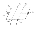
さて、上記食器かご6の周囲には、図2に示すように、複数組、この場合3組の光センサ15,16,17が設けられている。これら各光センサ15〜17は、食器かご6に載置される食器類7,8の配置位置を検出するためのものであり、それぞれ発光素子18a,18b,18cと受光素子19a,19b,19cとを対向配置して構成されている。これらのうち1組の光センサ15の発光素子18aと受光素子19aは、洗浄槽2の左右両側壁に位置させて食器かご6を挟むように配置されている。この光センサ15の発光素子18aと受光素子19aは、洗浄槽2の前後方向のほぼ中央部に配置されている。
【0014】
また、残りの2組の光センサ16,17の各発光素子18b,18cは、図示しない扉の内部に配置され、また、各受光素子19b,19cは、洗浄槽2の後壁に、対応する発光素子18b,18cと対向して食器かご6を挟むように配置されている。2組の光センサ16,17のうち一方の光センサ16は、洗浄槽2の左右方向の中央部よりやや左寄りに配置され、他方の光センサ17は、洗浄槽2の左右方向の中央部よりやや右寄りに配置されている。
【0015】
本体1の下部の前面には操作パネル21が設けられていて、この操作パネル21に、図示はしないが操作スイッチや表示部が設けられている。そして、操作パネル21の裏側には、制御手段を構成する制御装置22が設けられている。この制御装置22は、例えばマイクロコンピュータから構成されていて、食器洗い乾燥機における洗い運転及び乾燥運転の動作全般を制御する制御プログラムを有している。なお、本体1内には、図示はしないが、洗浄槽2内に給水するための給水弁、洗浄槽2内の水位を検出する水位センサ、洗浄槽2内の洗浄水を外部へ排出するための排水ポンプなどが配設されている。
【0016】
次に上記構成の作用を説明する。
まず、使用者は、食器かご6に食器類7,8を載置すると共に、この食器かご6を洗浄槽2内に収容する。そして、洗剤を投入した後、扉を閉め、操作パネル21の操作スイッチを操作する。このとき、使用者は、標準コースを設定したとする。すると、制御装置22は、この標準コースでは、例えば、配置位置検出行程、洗い行程、2回のすすぎ行程、温水すすぎ行程、乾燥行程を順に実行する。
【0017】
まず、配置位置検出行程では、制御装置22は、光センサ15〜17により、食器かご6に載置された食器類7,8の配置位置を検出する。ここでは、説明を簡単にするため、食器類7,8は、図1に示す左右の2箇所のみに配置されるものとする。各光センサ15〜17は、発光素子18a,18b,18cから発せられた光が食器類7,8により遮断されると、受光素子19a,19b,19cによりその光を受けることができなくなるため、これにより食器類7,8の配置位置を検出する。この検出結果は制御装置22に入力される。制御装置22は、これら光センサ15〜17の検出結果に基づき、ファン装置10の送風口13に対する食器類7,8の配置位置を検出する。
【0018】
この場合、左右の光センサ16,17のうち、左側の光センサ16のみが食器類7を検出した場合(受光素子19bが受光しなかった場合)には、制御装置22は、食器類7が「左のみ」に配置されていると判定し、右側の光センサ17のみが食器類8を検出した場合(受光素子19cが受光しなかった場合)には、制御装置22は、食器類8が「右のみ」に配置されていると判定し、左右の両光センサ16,17が食器類7,8を検出した場合(受光素子19b,19cが受光しなかった場合)には、制御装置22は、食器類7,8が「左右両方」に配置されていると判定する。
【0019】
そして、食器類7,8の前後方向の配置位置を検出する光センサ15は、上記同様に、食器類7,8が図2に示すように前後方向の中央に配置されているか否かを検出する。
【0020】
次に、制御装置22は、洗い行程を実行する。洗い行程では、まず給水弁を開放して洗浄槽2内に所定の設定水位まで給水する。そして、ヒータ4を通電して洗浄水を加熱すると共に、洗浄ポンプを駆動して洗浄ノズル3から洗浄水を食器類7,8に向けて噴射する。このとき、洗浄ノズル3は、噴射の反動により回転する。この洗浄水の噴射により、食器かご6内の食器類7,8が洗浄される。そして、所定時間が経過するか、または、温度センサ5の検出温度が予め設定された温度に達したことを検出すると、ヒータ4を断電すると共に、洗浄ポンプの駆動を停止させた後、排水ポンプを駆動して洗浄槽2内の洗浄水を排出する。これにより、洗い行程が終了する。
【0021】
次に、制御装置22は、すすぎ行程を実行する。すすぎ行程では、まず、給水弁を開放して洗浄槽2内に所定の設定水位まで給水した後、洗浄ポンプを駆動して洗浄ノズル3から洗浄水を食器類7,8に向けて噴射することによって行う。所定の設定時間が経過したら、洗浄ポンプの駆動を停止させた後、排水ポンプを駆動して洗浄槽2内の洗浄水を排出する。このようなすすぎ行程を2回行う。
【0022】
次に、制御装置22は、温水すすぎ行程を実行する。温水すすぎ行程では、給水弁を開放して洗浄槽2内に所定の設定水位まで給水した後、ヒータ4を通電して洗浄水を加熱すると共に、洗浄ポンプを駆動して洗浄ノズル3から洗浄水を食器類7,8に向けて噴射することによって行う。所定の設定時間が経過するか、または、温度センサ5の検出温度が予め設定された温度に達したことを検出すると、ヒータ4を断電すると共に、洗浄ポンプの駆動を停止させた後、排水ポンプを駆動して洗浄槽2内の洗浄水を排出する。これにより、温水すすぎ行程が終了する。
【0023】
次に、制御装置22は、乾燥行程を実行する。乾燥行程では、ヒータ4を通電して発熱させると共に、ファン装置10を運転して送風口13から洗浄槽2内に送風する。この発熱と風とにより、食器類7,8が乾燥される。
【0024】
このとき、制御装置22は、配置位置検出行程において検出した結果に基づいて、ファン装置10の運転を制御する。具体的には、図3に示すように、配置位置検出行程において検出した結果が、左側の食器類7のみと判定した場合には、食器類7は送風口13から遠くにのみあるため、ファン装置10を強めの運転に設定する(ファンモータ12の回転速度を通常よりも高くする)。配置位置検出行程において検出した結果が、右側の食器類8のみと判定した場合には、食器類8は送風口13の近くのみにあるため、ファン装置10を弱めの運転に設定する(ファンモータ12の回転速度を通常よりも低くする)。そして、配置位置検出行程において検出した結果が、左右両側の食器類7、8があると判定した場合には、ファン装置10を通常運転に設定する(ファンモータ12を通常の回転速度に設定する)。
【0025】
更に、光センサ16,17により食器類7,8が検出された場合において、光センサ15が食器類7,8を検出した時は上記制御が変わることはないが、検出しなかった時は食器類7,8が前後方向に偏在しており、食器類7,8は送風口13からは更に遠い配置なっている。よって、この場合は、ファン装置10の上記強め・弱めの運転よりファンモータ12の回転速度を少し高く設定するようにファン装置10を制御する。
この乾燥行程の設定時間が経過したら、ヒータ4を断電すると共に、ファン装置10の運転を停止する。これにより、洗い運転と乾燥運転とが完了する。
【0026】
上記した実施例によれば、光センサ15〜17により、送風口13に対する食器類7,8の配置位置を検出し、この検出結果に基づきファン装置10の送風能力を可変制御する構成としたので、余分なエネルギーを節約することが可能となると共に、乾き残しを防ぎ、確実に乾燥させることが可能となる。よって、ファン装置10の送風口13に対する食器類7,8の配置位置に応じて乾燥を効率よく行うことができる。
【0027】
なお、上記した実施例においては、光センサ15〜17を3組使用した例を示したが、もっと多数組使用して、食器類の配置位置をより細かく検出し、それに基づき、より細かい制御を行うことも可能であり、逆に光センサ15は必要に応じて設ければよく、なくてもよいものである。また、食器類7,8の配置位置の検出を、乾燥行程の直前に行うようにしてもよい。
【0028】
図4は本発明の第2実施例を示したものであり、この第2実施例は上記した第1実施例とは次の点が異なっている。
すなわち、食器類の配置位置を検出するための光センサ15〜17は設けず、代わりに、操作パネル21に、配置位置入力手段として配置位置入力用のスイッチ25,26,27を設けると共に、表示部28,29,30を設けている。
【0029】
ここで、上記食器かご6の左右両側に食器類7,8を配置した場合には、使用者は、「通常(両方)」のスイッチ25を押す。すると、制御装置22は、両方の表示部28を点灯する。そして、乾燥行程の際には、制御装置22は、ファン装置10のファンモータ12を通常の回転速度で運転する。
食器かご6の左側のみに食器類7を配置した場合には、使用者は、「左のみ」のスイッチ26を押す。すると、制御装置22は、左の表示部29のみを点灯する。そして、乾燥行程の際には、ファン装置10のファンモータ12を通常よりも高い回転速度で運転する。
【0030】
食器かご6の右側のみに食器類8を配置した場合には、使用者は、「右のみ」のスイッチ27を押す。すると、制御装置22は、右の表示部30のみを点灯する。そして、乾燥行程の際には、ファン装置10のファンモータ12を通常よりも低い回転速度で運転する。
このような第2実施例においても、第1実施例と同様の作用効果を得ることができる。
【0031】
本発明は、上記した両実施例にのみ限定されるものではなく、次のように変形または拡張できる。
第1実施例においては光センサ15〜17による配置位置の検出結果に基づき、また、第2実施例においては配置位置入力用のスイッチ25〜27の入力情報に基づき、ファン装置10の送風能力(ファンモータ12の回転速度)を変更するようにしたが、これに代えて、例えば、乾燥行程の運転時間を変更するようにしたり、ヒータ4の発熱量(ひいては乾燥時の温度)を変更するようにしたりすることも可能である。
【0032】
本発明は、洗浄槽2内に食器かごが上下2段に設置される場合にも適用できる。この場合、ファン装置10も、それら食器かごに対応させて上下2段に設ける。また、このような構成において、洗浄ノズルも食器かごに対応させて上下2段に設け、各食器かごに対応させて、食器類の配置位置検出用の光センサ15〜17を設け、洗い行程やすすぎ行程において、それら光センサ15〜17の検出結果に基づき、使用する洗浄ノズルや噴射圧力を制御したり、乾燥行程において、使用するファン装置10やファン装置10の回転速度を制御したりすることも可能である。
【0033】
本発明は、洗浄手段がない食器乾燥機にも適用できる。
配置位置検出手段としては、透過型の光センサ15〜17に限られず、反射型の光センサ、赤外線センサ、超音波センサなどであってもよい。
【0034】
【発明の効果】
以上の説明から明らかなように、請求項1の発明によれば、乾燥手段の送風口に対する食器類の配置位置を配置位置検出手段により検出し、その検出結果に基づき乾燥手段を制御することにより、乾燥手段の送風口に対する食器類の配置位置に応じて乾燥を効率よく行うことができる。
また、請求項2の発明によれば、乾燥手段の送風口に対する食器類の配置位置を配置位置検出入力手段により入力し、その入力情報に基づき乾燥手段を制御することにより、乾燥手段の送風口に対する食器類の配置位置に応じて乾燥を効率よく行うことができる。
【図面の簡単な説明】
【図1】本発明の第1実施例を示すもので、正面側から見た食器洗い乾燥機の概略構成図
【図2】光センサの配置を示すための図
【図3】配置位置とファン装置の運転内容との関係を示す図
【図4】本発明の第2実施例を示すもので、配置位置入力用のスイッチ及び表示部を示す正面図
【符号の説明】
1は本体、2は洗浄槽(乾燥室)、3は洗浄ノズル、4はヒータ(乾燥手段)、6は食器かご(食器載置体)、7,8は食器類、10はファン装置(乾燥手段)、13は送風口、15,16,17は光センサ(配置位置検出手段)、18a,18b,18cは発光素子、19a,19b,19cは受光素子、21は操作パネル、22は制御装置(制御手段)、25,26,27は配置位置入力用のスイッチ(配置位置入力手段)、28,29,30は表示部を示す。[0001]
TECHNICAL FIELD OF THE INVENTION
The present invention relates to a dish dryer including drying means for blowing air into a drying chamber to dry dishes in the drying chamber.
[0002]
[Prior art]
2. Description of the Related Art Conventionally, for example, in a dishwasher / dryer, a capacity detecting unit (for example, a weight sensor) for detecting the capacity (weight) of tableware (object to be washed) placed in a tableware basket stored in a washing tank also serving as a drying chamber. When the detection capacity of the capacity detection means changes, the operation is performed by changing the drying time of the drying means, the blowing capacity of the blowing means, the energization time of the heater, and the like according to the change in the capacity. It is known that drying is ensured, and drying time and power consumption are optimized even if there is a change in the tableware capacity (for example, see Patent Document 1).
[0003]
[Patent Document 1]
JP-A-11-332814 (paragraphs [0032] to [0061])
[0004]
[Problems to be solved by the invention]
In the above-described conventional configuration, the capacity detecting means detects the capacity (weight) of the tableware, and has no relation to the arrangement position of the tableware. By the way, when drying tableware, the drying efficiency differs depending on the arrangement position of the tableware with respect to the air outlet of the blowing means. However, such a thing has not been taken into consideration in the conventional apparatus.
[0005]
The present invention has been made in view of the above circumstances, and an object of the present invention is to provide a tableware dryer capable of performing drying efficiently according to the arrangement position of tableware with respect to an air outlet of a drying unit.
[0006]
[Means for Solving the Problems]
In order to achieve the above object, a dish dryer according to the first aspect of the present invention includes a drying chamber, a tableware body accommodated in the drying chamber, and a tableware on which tableware is mounted, and a ventilation opening, which is provided in the drying chamber. A drying unit that blows the tableware to dry the dishes, an arrangement position detection unit that detects an arrangement position of the tableware with respect to the air outlet, and a control that controls the drying unit based on a detection result of the arrangement position detection unit. Means.
[0007]
When the arrangement position of the dishes detected by the arrangement position detection means is, for example, only in a place where the wind is easy to hit, such as near the air outlet, the dishes are easy to dry, so that the blowing ability of the drying means is weakened. By shortening the drying time, it is possible to save extra energy. In addition, when the arrangement position of the tableware detected by the arrangement position detection unit is far from the air outlet or only in a place where the wind is difficult to hit, since the tableware is hard to dry, the blowing capacity of the drying unit is strongly increased. Or by extending the drying time, to prevent undried and ensure drying. By performing such control, drying can be efficiently performed in accordance with the arrangement position of the tableware with respect to the air outlet of the drying unit.
[0008]
In order to achieve the same object as described above, the tableware dryer according to the second aspect of the present invention includes a drying chamber, a tableware body accommodated in the drying chamber, and a tableware on which tableware is mounted, and a blower opening. A drying unit that blows air into the drying chamber to dry the dishes, an arrangement position input unit that inputs an arrangement position of the dishes with respect to the air outlet, and controls the drying unit based on input information of the arrangement position input unit. And control means for performing the control.
[0009]
If the tableware obtained from the input information of the arrangement position input means is located only in a place where the wind easily hits, for example, near the air outlet, the dishes are easy to dry, and the blowing capacity of the drying means By reducing the drying time and shortening the drying time, it is possible to save extra energy. Further, when the tableware placement position obtained by the input information of the placement position input means is only a place far from the air outlet or hardly exposed to the wind, since the tableware is hard to dry, the drying means By strengthening the ability and lengthening the drying time, it is possible to prevent the remaining dryness and ensure the drying. By performing such control, drying can be efficiently performed in accordance with the arrangement position of the tableware with respect to the air outlet of the drying unit.
[0010]
BEST MODE FOR CARRYING OUT THE INVENTION
Hereinafter, a first embodiment in which the present invention is applied to a dishwasher will be described with reference to FIGS.
First, FIG. 1 shows a schematic configuration diagram of a dishwasher viewed from the front side. In FIG. 1, a
[0011]
A
[0012]
On the outside of the right side wall of the
[0013]
As shown in FIG. 2, a plurality of sets, in this case, three sets of
[0014]
The light emitting elements 18b and 18c of the remaining two sets of
[0015]
An
[0016]
Next, the operation of the above configuration will be described.
First, the user places the
[0017]
First, in the arrangement position detection process, the
[0018]
In this case, when only the left
[0019]
Then, the
[0020]
Next, the
[0021]
Next,
[0022]
Next,
[0023]
Next, the
[0024]
At this time, the
[0025]
Further, when the
When the set time of the drying process has elapsed, the heater 4 is turned off and the operation of the
[0026]
According to the above-described embodiment, the arrangement position of the
[0027]
In the above-described embodiment, an example in which three sets of the
[0028]
FIG. 4 shows a second embodiment of the present invention. The second embodiment differs from the first embodiment in the following points.
That is, the
[0029]
Here, when the
When the
[0030]
When the tableware 8 is arranged only on the right side of the tableware basket 6, the user presses the “right only” switch 27. Then, the
In the second embodiment, the same operation and effect as those of the first embodiment can be obtained.
[0031]
The present invention is not limited to only the above-described embodiments, but can be modified or expanded as follows.
In the first embodiment, based on the detection result of the arrangement position by the
[0032]
The present invention can also be applied to a case where tableware baskets are installed in the
[0033]
The present invention can be applied to a dish dryer having no washing means.
The arrangement position detecting means is not limited to the transmission type
[0034]
【The invention's effect】
As is clear from the above description, according to the first aspect of the present invention, the arrangement position of the tableware with respect to the air outlet of the drying unit is detected by the arrangement position detection unit, and the drying unit is controlled based on the detection result. In addition, the drying can be efficiently performed according to the arrangement position of the tableware with respect to the blowing port of the drying unit.
According to the second aspect of the present invention, the arrangement position of the tableware with respect to the air outlet of the drying means is input by the arrangement position detection input means, and the drying means is controlled based on the input information, whereby the air outlet of the drying means is controlled. Drying can be performed efficiently according to the arrangement position of the tableware with respect to.
[Brief description of the drawings]
FIG. 1 shows a first embodiment of the present invention, and is a schematic configuration diagram of a dishwasher viewed from the front side. FIG. 2 is a view showing an arrangement of an optical sensor. FIG. 3 is an arrangement position and a fan device. FIG. 4 shows a second embodiment of the present invention, and is a front view showing a switch for inputting an arrangement position and a display unit.
1 is a main body, 2 is a washing tank (drying room), 3 is a washing nozzle, 4 is a heater (drying means), 6 is a tableware basket (tableware placing body), 7, 8 are tableware, and 10 is a fan device (drying). Means, 13 is an air outlet, 15, 16, 17 are optical sensors (arrangement position detecting means), 18a, 18b, 18c are light emitting elements, 19a, 19b, 19c are light receiving elements, 21 is an operation panel, and 22 is a control device. (Control means), 25, 26, and 27 indicate switches for inputting arrangement positions (arrangement position input means), and 28, 29, and 30 indicate display units.
Claims (2)
この乾燥室内に収容され、食器類が載置される食器載置体と、
送風口から前記乾燥室内に送風して前記食器類を乾燥させる乾燥手段と、
前記送風口に対する前記食器類の配置位置を検出する配置位置検出手段と、
この配置位置検出手段の検出結果に基づき前記乾燥手段を制御する制御手段とを具備したことを特徴とする食器乾燥機。Drying room,
A tableware placed in the drying chamber and on which tableware is placed;
Drying means for blowing the tableware by blowing into the drying chamber from an air outlet,
Arrangement position detecting means for detecting an arrangement position of the tableware with respect to the air outlet,
And a control means for controlling the drying means based on the detection result of the arrangement position detecting means.
この乾燥室内に収容され、食器類が載置される食器載置体と、
送風口から前記乾燥室内に送風して前記食器類を乾燥させる乾燥手段と、
前記送風口に対する前記食器類の配置位置を入力する配置位置入力手段と、
この配置位置入力手段の入力情報に基づき前記乾燥手段を制御する制御手段とを具備したことを特徴とする食器乾燥機。Drying room,
A tableware placed in the drying chamber and on which tableware is placed;
Drying means for blowing the tableware by blowing into the drying chamber from an air outlet,
An arrangement position input means for inputting an arrangement position of the tableware with respect to the air outlet,
And a control means for controlling the drying means based on the input information of the arrangement position input means.
Priority Applications (1)
| Application Number | Priority Date | Filing Date | Title |
|---|---|---|---|
| JP2003075563A JP2004283209A (en) | 2003-03-19 | 2003-03-19 | Dish dryer |
Applications Claiming Priority (1)
| Application Number | Priority Date | Filing Date | Title |
|---|---|---|---|
| JP2003075563A JP2004283209A (en) | 2003-03-19 | 2003-03-19 | Dish dryer |
Publications (1)
| Publication Number | Publication Date |
|---|---|
| JP2004283209A true JP2004283209A (en) | 2004-10-14 |
Family
ID=33290849
Family Applications (1)
| Application Number | Title | Priority Date | Filing Date |
|---|---|---|---|
| JP2003075563A Pending JP2004283209A (en) | 2003-03-19 | 2003-03-19 | Dish dryer |
Country Status (1)
| Country | Link |
|---|---|
| JP (1) | JP2004283209A (en) |
Cited By (7)
| Publication number | Priority date | Publication date | Assignee | Title |
|---|---|---|---|---|
| JP2008119152A (en) * | 2006-11-10 | 2008-05-29 | Matsushita Electric Ind Co Ltd | Dishwasher |
| JP2009273755A (en) * | 2008-05-16 | 2009-11-26 | Panasonic Corp | Dishwasher |
| JP2010263942A (en) * | 2009-05-12 | 2010-11-25 | Panasonic Corp | Dishwasher |
| US8696827B2 (en) | 2010-12-01 | 2014-04-15 | Whirlpool Corporation | Dishwasher with imaging device for measuring load characteristics and a method for controlling same |
| JP2018134157A (en) * | 2017-02-20 | 2018-08-30 | ホシザキ株式会社 | Operation method of sterilization storage cabinet |
| WO2019015969A1 (en) * | 2017-07-18 | 2019-01-24 | BSH Hausgeräte GmbH | Dishwasher comprising at least one fan impeller in the dishwashing compartment |
| CN110419992A (en) * | 2019-06-24 | 2019-11-08 | 青岛海尔洗碗机有限公司 | A kind of control method of dish-washing machine |
-
2003
- 2003-03-19 JP JP2003075563A patent/JP2004283209A/en active Pending
Cited By (9)
| Publication number | Priority date | Publication date | Assignee | Title |
|---|---|---|---|---|
| JP2008119152A (en) * | 2006-11-10 | 2008-05-29 | Matsushita Electric Ind Co Ltd | Dishwasher |
| JP2009273755A (en) * | 2008-05-16 | 2009-11-26 | Panasonic Corp | Dishwasher |
| JP2010263942A (en) * | 2009-05-12 | 2010-11-25 | Panasonic Corp | Dishwasher |
| US8696827B2 (en) | 2010-12-01 | 2014-04-15 | Whirlpool Corporation | Dishwasher with imaging device for measuring load characteristics and a method for controlling same |
| JP2018134157A (en) * | 2017-02-20 | 2018-08-30 | ホシザキ株式会社 | Operation method of sterilization storage cabinet |
| WO2019015969A1 (en) * | 2017-07-18 | 2019-01-24 | BSH Hausgeräte GmbH | Dishwasher comprising at least one fan impeller in the dishwashing compartment |
| CN110944561A (en) * | 2017-07-18 | 2020-03-31 | Bsh家用电器有限公司 | Dishwasher with at least one fan wheel in a rinsing container |
| US11399689B2 (en) | 2017-07-18 | 2022-08-02 | BSH Hausgeräte GmbH | Dishwasher comprising at least one fan impeller in the dishwashing compartment |
| CN110419992A (en) * | 2019-06-24 | 2019-11-08 | 青岛海尔洗碗机有限公司 | A kind of control method of dish-washing machine |
Similar Documents
| Publication | Publication Date | Title |
|---|---|---|
| EP1921195A2 (en) | Washing machine | |
| JP2004154565A (en) | Dishwasher equipped with hot air generator | |
| JP2004283209A (en) | Dish dryer | |
| JP3059861B2 (en) | Dishwasher | |
| JP2001112686A (en) | Dishwasher | |
| JP2007202828A (en) | Dishwasher | |
| JP4802212B2 (en) | Tableware dryer | |
| JPH07227374A (en) | Dryer and washer | |
| JP2004283431A (en) | Dish washer/dryer | |
| KR20070002441A (en) | Apparatus for drying dishes of dish washer | |
| JP2004261295A (en) | Dishwasher | |
| JP2000350693A (en) | Dish washer | |
| KR20040040303A (en) | Dish washer having heated air generator | |
| JP2001078948A (en) | Dishwasher | |
| JP5923481B2 (en) | Dishwasher | |
| JP2005130924A (en) | Dishwasher | |
| JP2006110151A (en) | Dish washer/dryer and dish washing/drying control method | |
| JP4354413B2 (en) | Dishwasher | |
| JP4129412B2 (en) | Dishwasher | |
| JP2011200392A (en) | Dish washing and drying machine | |
| JP2003180599A (en) | Dishwasher | |
| JP2007181518A (en) | Dishwasher | |
| JP2006068400A (en) | Dish washer and dryer | |
| JP4457731B2 (en) | Dishwasher | |
| KR100211261B1 (en) | Dishwasher of a dry apparatus and method |