JP2004276900A - Aircraft, transport aircraft, and manufacturing method for aircraft - Google Patents
Aircraft, transport aircraft, and manufacturing method for aircraft Download PDFInfo
- Publication number
- JP2004276900A JP2004276900A JP2003350979A JP2003350979A JP2004276900A JP 2004276900 A JP2004276900 A JP 2004276900A JP 2003350979 A JP2003350979 A JP 2003350979A JP 2003350979 A JP2003350979 A JP 2003350979A JP 2004276900 A JP2004276900 A JP 2004276900A
- Authority
- JP
- Japan
- Prior art keywords
- aircraft
- wing
- fuselage
- torso
- leading edge
- Prior art date
- Legal status (The legal status is an assumption and is not a legal conclusion. Google has not performed a legal analysis and makes no representation as to the accuracy of the status listed.)
- Pending
Links
- 238000004519 manufacturing process Methods 0.000 title claims abstract description 7
- 230000003068 static effect Effects 0.000 claims description 28
- 239000003381 stabilizer Substances 0.000 claims description 26
- 238000000034 method Methods 0.000 claims description 15
- 238000003860 storage Methods 0.000 claims description 10
- 239000002828 fuel tank Substances 0.000 claims description 8
- 238000009826 distribution Methods 0.000 claims description 5
- 230000008901 benefit Effects 0.000 description 10
- 230000009471 action Effects 0.000 description 9
- 239000000446 fuel Substances 0.000 description 7
- 230000032258 transport Effects 0.000 description 6
- 238000012546 transfer Methods 0.000 description 5
- 238000013459 approach Methods 0.000 description 4
- 230000002411 adverse Effects 0.000 description 2
- 238000005452 bending Methods 0.000 description 2
- 238000006073 displacement reaction Methods 0.000 description 2
- 238000005192 partition Methods 0.000 description 2
- 230000009467 reduction Effects 0.000 description 2
- 230000004888 barrier function Effects 0.000 description 1
- 238000013461 design Methods 0.000 description 1
- 230000001066 destructive effect Effects 0.000 description 1
- 238000005516 engineering process Methods 0.000 description 1
- 230000003993 interaction Effects 0.000 description 1
- 230000007246 mechanism Effects 0.000 description 1
- 238000012986 modification Methods 0.000 description 1
- 230000004048 modification Effects 0.000 description 1
- 238000005728 strengthening Methods 0.000 description 1
Images


Classifications
-
- B—PERFORMING OPERATIONS; TRANSPORTING
- B64—AIRCRAFT; AVIATION; COSMONAUTICS
- B64C—AEROPLANES; HELICOPTERS
- B64C1/00—Fuselages; Constructional features common to fuselages, wings, stabilising surfaces or the like
- B64C1/0009—Aerodynamic aspects
-
- B—PERFORMING OPERATIONS; TRANSPORTING
- B64—AIRCRAFT; AVIATION; COSMONAUTICS
- B64C—AEROPLANES; HELICOPTERS
- B64C1/00—Fuselages; Constructional features common to fuselages, wings, stabilising surfaces or the like
- B64C1/26—Attaching the wing or tail units or stabilising surfaces
-
- B—PERFORMING OPERATIONS; TRANSPORTING
- B64—AIRCRAFT; AVIATION; COSMONAUTICS
- B64C—AEROPLANES; HELICOPTERS
- B64C25/00—Alighting gear
- B64C25/02—Undercarriages
- B64C25/04—Arrangement or disposition on aircraft
-
- B—PERFORMING OPERATIONS; TRANSPORTING
- B64—AIRCRAFT; AVIATION; COSMONAUTICS
- B64C—AEROPLANES; HELICOPTERS
- B64C25/00—Alighting gear
- B64C25/02—Undercarriages
- B64C25/08—Undercarriages non-fixed, e.g. jettisonable
- B64C25/10—Undercarriages non-fixed, e.g. jettisonable retractable, foldable, or the like
-
- B—PERFORMING OPERATIONS; TRANSPORTING
- B64—AIRCRAFT; AVIATION; COSMONAUTICS
- B64D—EQUIPMENT FOR FITTING IN OR TO AIRCRAFT; FLIGHT SUITS; PARACHUTES; ARRANGEMENTS OR MOUNTING OF POWER PLANTS OR PROPULSION TRANSMISSIONS IN AIRCRAFT
- B64D11/00—Passenger or crew accommodation; Flight-deck installations not otherwise provided for
-
- B—PERFORMING OPERATIONS; TRANSPORTING
- B64—AIRCRAFT; AVIATION; COSMONAUTICS
- B64D—EQUIPMENT FOR FITTING IN OR TO AIRCRAFT; FLIGHT SUITS; PARACHUTES; ARRANGEMENTS OR MOUNTING OF POWER PLANTS OR PROPULSION TRANSMISSIONS IN AIRCRAFT
- B64D27/00—Arrangement or mounting of power plant in aircraft; Aircraft characterised thereby
- B64D27/02—Aircraft characterised by the type or position of power plant
- B64D27/16—Aircraft characterised by the type or position of power plant of jet type
- B64D27/18—Aircraft characterised by the type or position of power plant of jet type within or attached to wing
-
- B—PERFORMING OPERATIONS; TRANSPORTING
- B64—AIRCRAFT; AVIATION; COSMONAUTICS
- B64D—EQUIPMENT FOR FITTING IN OR TO AIRCRAFT; FLIGHT SUITS; PARACHUTES; ARRANGEMENTS OR MOUNTING OF POWER PLANTS OR PROPULSION TRANSMISSIONS IN AIRCRAFT
- B64D37/00—Arrangements in connection with fuel supply for power plant
- B64D37/02—Tanks
- B64D37/04—Arrangement thereof in or on aircraft
-
- B—PERFORMING OPERATIONS; TRANSPORTING
- B64—AIRCRAFT; AVIATION; COSMONAUTICS
- B64D—EQUIPMENT FOR FITTING IN OR TO AIRCRAFT; FLIGHT SUITS; PARACHUTES; ARRANGEMENTS OR MOUNTING OF POWER PLANTS OR PROPULSION TRANSMISSIONS IN AIRCRAFT
- B64D9/00—Equipment for handling freight; Equipment for facilitating passenger embarkation or the like
- B64D9/003—Devices for retaining pallets or freight containers
-
- B—PERFORMING OPERATIONS; TRANSPORTING
- B64—AIRCRAFT; AVIATION; COSMONAUTICS
- B64C—AEROPLANES; HELICOPTERS
- B64C1/00—Fuselages; Constructional features common to fuselages, wings, stabilising surfaces or the like
- B64C2001/0018—Fuselages; Constructional features common to fuselages, wings, stabilising surfaces or the like comprising two decks adapted for carrying passengers only
- B64C2001/0027—Fuselages; Constructional features common to fuselages, wings, stabilising surfaces or the like comprising two decks adapted for carrying passengers only arranged one above the other
-
- B—PERFORMING OPERATIONS; TRANSPORTING
- B64—AIRCRAFT; AVIATION; COSMONAUTICS
- B64C—AEROPLANES; HELICOPTERS
- B64C1/00—Fuselages; Constructional features common to fuselages, wings, stabilising surfaces or the like
- B64C2001/0045—Fuselages characterised by special shapes
-
- Y—GENERAL TAGGING OF NEW TECHNOLOGICAL DEVELOPMENTS; GENERAL TAGGING OF CROSS-SECTIONAL TECHNOLOGIES SPANNING OVER SEVERAL SECTIONS OF THE IPC; TECHNICAL SUBJECTS COVERED BY FORMER USPC CROSS-REFERENCE ART COLLECTIONS [XRACs] AND DIGESTS
- Y02—TECHNOLOGIES OR APPLICATIONS FOR MITIGATION OR ADAPTATION AGAINST CLIMATE CHANGE
- Y02T—CLIMATE CHANGE MITIGATION TECHNOLOGIES RELATED TO TRANSPORTATION
- Y02T50/00—Aeronautics or air transport
- Y02T50/10—Drag reduction
-
- Y—GENERAL TAGGING OF NEW TECHNOLOGICAL DEVELOPMENTS; GENERAL TAGGING OF CROSS-SECTIONAL TECHNOLOGIES SPANNING OVER SEVERAL SECTIONS OF THE IPC; TECHNICAL SUBJECTS COVERED BY FORMER USPC CROSS-REFERENCE ART COLLECTIONS [XRACs] AND DIGESTS
- Y02—TECHNOLOGIES OR APPLICATIONS FOR MITIGATION OR ADAPTATION AGAINST CLIMATE CHANGE
- Y02T—CLIMATE CHANGE MITIGATION TECHNOLOGIES RELATED TO TRANSPORTATION
- Y02T50/00—Aeronautics or air transport
- Y02T50/40—Weight reduction
Abstract
Description
関連出願の相互参照
この出願は、2002年10月10日に提出された係属中の米国仮特許出願第60/417,885号、2002年10月22日に提出された係属中の米国特許出願第10/278,633号、および2002年10月22日に提出された係属中の米国特許出願第10/278,717号の利益を主張し、これらの各々の全体が、ここで引用により援用される。
CROSS REFERENCE TO RELATED APPLICATIONS This application is a pending U.S. Provisional Patent Application No. 60 / 417,885, filed October 10, 2002, and a pending U.S. Patent Application No. No. 10 / 278,633, and pending US patent application Ser. No. 10 / 278,717, filed Oct. 22, 2002, each of which is incorporated herein by reference in its entirety. Is done.
技術分野
以下の開示は、一般に、高速航空機に関し、より具体的には、一体型高速輸送機に関する。
TECHNICAL FIELD The following disclosure relates generally to high-speed aircraft, and more specifically to integrated high-speed transports.
背景
商業用の輸送機は、通例、約0.85以下の飛行マッハ数で飛行する。遷音速または超音速等のより高い速度で乗客および貨物を輸送することによって、移動時間が短縮され、さらには収益を上げることができるが、このような速度で飛行することにより、より大きな推力が必要とされる。より大きな推力を生成するために、従来の遷音速および超音速航空機は、通例、低バイパス比ターボファンエンジンまたはストレートターボジェットエンジンを用いる。これらのエンジン構成は、一般に、飛行状態では高い燃料消費率を持ち、これは、これらが提供し得るいずれの空力効率の上昇よりも影響力がある。この燃料消費によって、結果として、遷音速および超音速航空機の正味の燃料効率が、同程度の大きさの亜音速航空機のそれよりも著しく低くなる。加えて、この低い燃料効率によって、不利なことには、大気放出が増加され得る。
BACKGROUND Commercial transport aircraft typically fly at flight Mach numbers of about 0.85 or less. Transporting passengers and cargo at higher speeds, such as transonic or supersonic speeds can reduce travel time and even increase revenue, but flying at such speeds results in greater thrust. Needed. To produce greater thrust, conventional transonic and supersonic aircraft typically employ a low bypass ratio turbofan engine or a straight turbojet engine. These engine configurations generally have a high fuel consumption rate in flight, which is more influential than any aerodynamic increase they can provide. This fuel consumption results in significantly lower net fuel efficiency for transonic and supersonic aircraft than for similarly sized subsonic aircraft. In addition, this low fuel efficiency can disadvantageously increase atmospheric emissions.
従来の遷音速および超音速航空機エンジンは、通例、離陸のために推力を生成するとき、非常に高いジェット速度で動作する。これらの速度によって、空港および周辺地域において著しい騒音が発生し得る。この騒音を減じるための1つの手法は、エンジン吸気口およびノズルダクトを長くし、騒音減少要素をダクトと一体化することである。この手法の1つの欠点は、このような要素によって、通例、推進システムの重量が増加し、これにより、翼上の構造的な荷重が増加し、航空機が翼のフラッタを受ける可能性が高まることである。このような追加的な荷重を支えるために翼を強化することによって、結果として、構造的な重量が増加し、これによってさらに、航空機の空力抵抗が増大する傾向がある。このように空力抵抗が増大することによって、燃料消費が上昇し、これにより、航空機が運ばなければならない燃料の量が増加する。しかしながら、燃料能力を上げることは、航空機の構造的な重量をさらに増加させ、設計サイクルが繰返されることになる。 Conventional transonic and supersonic aircraft engines typically operate at very high jet velocities when generating thrust for takeoff. These speeds can generate significant noise at airports and surrounding areas. One approach to reducing this noise is to lengthen the engine inlet and nozzle ducts and integrate noise reduction elements with the ducts. One drawback of this approach is that such elements typically increase the weight of the propulsion system, which increases the structural load on the wing and increases the likelihood that the aircraft will experience wing flutter. It is. Strengthening the wing to support such additional loads results in increased structural weight, which in turn tends to increase the aerodynamic drag of the aircraft. This increase in aerodynamic drag increases fuel consumption, thereby increasing the amount of fuel that the aircraft must carry. However, increasing the fuel capacity further increases the structural weight of the aircraft, and the design cycle will be repeated.
従来の商業用の輸送機は、通例、上部デッキ上に客室、下部デッキ上に貨物室を含む。この構成は、選択されたルートにおいて乗客と貨物との両方を輸送することによって、航空会社が収益を上げることを可能にする。しかしながら、貨物輸送よりも、乗客輸送に対する需要が高いルートもいくつか存在し得る。したがって、このようなルートでは、航空会社は、さらなる乗客用の座席のために下部の貨物用デッキ上のスペースのうちのいくらかを用いることを好むであろう。 Conventional commercial transports typically include a cabin on the upper deck and a cargo hold on the lower deck. This configuration allows the airline to make money by transporting both passengers and cargo on selected routes. However, there may be some routes that have a higher demand for passenger transport than freight transport. Thus, on such routes, the airline would prefer to use some of the space on the lower cargo deck for additional passenger seats.
下部デッキに乗客用の座席および/または他の乗客用の設備を追加することに関する1つの問題点は、下部デッキは、通例、乗客および乗務員にとって十分ではない、立ったときの高さを提供することである。この様態で下部デッキを用いることに関する別の問題点
は、航空機は、通例、不時着等の衝撃が加わるときに乗客を保護するのには十分ではない構造を下部デッキの乗客用座席の下で提供することである。たとえば、現在の規則は、下部デッキが乗客用に用いられる場合、少なくとも30インチの圧縮性の構造を下部デッキの下で必要としている。
One problem with adding passenger seats and / or other passenger equipment to the lower deck is that the lower deck typically provides a standing height that is not sufficient for passengers and crew. That is. Another problem with using the lower deck in this manner is that aircraft typically provide structures below the lower deck passenger seats that are not sufficient to protect passengers in the event of impacts such as crash landings. It is to be. For example, current regulations require a compressible structure of at least 30 inches below the lower deck if the lower deck is to be used for passengers.
多くの航空機は、それらの翼に取付けられる引込式着陸装置を有する。これらの着陸装置は、一般に、航空機を地面上で支えるための静的展開位置と、飛行中の空力抵抗を減じるための静的格納位置との間で移動可能である。高い着陸荷重のために、これらの着陸装置は、通例、実質的な支持構造とともに翼に取付けられる。非常に強いことに加えて、このような支持構造は、静的展開位置と静的格納位置との間で着陸装置が移動することにも対応しなければならない。 Many aircraft have retractable landing gear mounted on their wings. These landing gears are generally movable between a static deployment position to support the aircraft on the ground and a static storage position to reduce aerodynamic drag during flight. For high landing loads, these landing gears are typically mounted on wings with substantial support structures. In addition to being very strong, such a support structure must also accommodate the movement of the landing gear between the static deployment position and the static storage position.
従来のいくつかの、翼に取付けられた着陸装置は、胴体から後方翼桁にまで延びる梁と後翼スパンとの間に、回動可能なように取付けられる。通例、高い着陸荷重を支えるために、梁は、比較的大きくなければならず、したがって、比較的重くなければならない。この手法に関する1つの欠点は、梁の追加的な重量によって、航空機の性能に悪影響が及ぼされ得ることである。 Some conventional wing-mounted landing gears are pivotally mounted between a beam extending from the fuselage to the aft spar and a rear wing span. Typically, to support high landing loads, the beams must be relatively large and, therefore, relatively heavy. One disadvantage with this approach is that the additional weight of the beam can adversely affect aircraft performance.
他の着陸装置が、後方翼桁の後方に延びる片持ち梁を備えて翼に取付けられる。片持ち梁は、通例、梁の中心線から横方向にずれており、かつ着陸装置の後方トラニオンを回動可能なように支持するように構成された後方トラニオン支持部を含む。片持ち梁の手法に付随する1つの欠点は、横方向のずれによって、結果として、着陸中に、かなりの片持ち梁のねじり荷重が生じることである。結果として、壊れることなくねじり荷重を支えるために、片持ち梁は、比較的大きくなければならず、したがって、比較的重くなければならない。上述のように、このような追加的な重量によって、航空機の性能に悪影響が与えられ得る。 Another landing gear is mounted on the wing with a cantilever that extends behind the aft spar. The cantilever typically includes a rear trunnion support that is laterally offset from the centerline of the beam and that is configured to pivotally support the rear trunnion of the landing gear. One disadvantage associated with the cantilever approach is that lateral displacement results in significant cantilever torsion loads during landing. As a result, to support torsional loads without breaking, the cantilever must be relatively large and, therefore, relatively heavy. As noted above, such additional weight can adversely affect aircraft performance.
概要
この発明の局面は、一体型高速輸送機等の航空機および関連の製造方法に関する。1つの局面では、航空機は、胴体、翼、および推進システムを含む。胴体は、第1の胴体部分と、第1の胴体部分の後方に位置付けられた第2の胴体部分と、第2の胴体部分の後方に位置付けられた第3の胴体部分とを含み得る。第1の胴体部分は、第1の断面積を有し得、第2の胴体部分は、第1の断面積よりも小さな第2の断面積を有し得、第3の胴体部分は、第2の断面積よりも大きな第3の断面積を有し得る。翼は、固定されるように胴体に取付けられ、第2の胴体部分に少なくとも隣接した位置から外側に向かって延びる。推進システムは、固定されるように翼に取付けられ、翼の前縁領域の後方に位置付けられる空気入口を含み得る。
SUMMARY Aspects of the present invention relate to aircraft such as integrated high speed transports and related manufacturing methods. In one aspect, an aircraft includes a fuselage, wings, and a propulsion system. The torso may include a first torso portion, a second torso portion located behind the first torso portion, and a third torso portion located behind the second torso portion. The first torso portion may have a first cross-sectional area, the second torso portion may have a second cross-sectional area smaller than the first cross-sectional area, and the third torso portion may have a first cross-sectional area. It may have a third cross-sectional area that is greater than two. The wing is fixedly attached to the fuselage and extends outwardly from a location at least adjacent to the second fuselage portion. The propulsion system may include an air inlet fixedly attached to the wing and positioned behind a leading edge region of the wing.
この発明の別の局面では、航空機を製造するための方法は、第1の断面積を有する第1の胴体部分を提供するステップと、第1の胴体部分の後方で、第2の胴体部分を第1の胴体部分に取付けるステップとを含む。第2の胴体部分は、第1の断面積よりも小さな第2の断面積を有し得る。この方法はさらに、第2の胴体部分の後方で、第3の胴体部分を第2の胴体部分に取付けるステップを含み得る。第3の胴体部分は、第2の断面積よりも大きな第3の断面積を有し得る。この方法はさらに、第2の胴体部分に少なくとも隣接して翼を取付けるステップと、推進システムを翼に取付けるステップとを含み得る。翼は、前縁領域を有し得、推進システムは、翼の前縁領域の後方に位置付けられた空気入口を有し得る。 In another aspect of the invention, a method for manufacturing an aircraft includes providing a first fuselage portion having a first cross-sectional area, and forming a second fuselage portion behind the first fuselage portion. Attaching to the first body part. The second body portion may have a second cross-sectional area smaller than the first cross-sectional area. The method may further include attaching the third torso portion to the second torso portion, behind the second torso portion. The third body portion may have a third cross-sectional area that is greater than the second cross-sectional area. The method may further include attaching the wing at least adjacent the second fuselage portion and attaching the propulsion system to the wing. The wing may have a leading edge region, and the propulsion system may have an air inlet located behind the leading edge region of the wing.
詳細な説明
以下の開示は、一体型高速輸送機等の航空機および関連の製造方法を説明する。特定の具体的な詳細が、以下の説明および図1−9において示されており、この発明のさまざまな実施例の完全な理解を提供する。しかしながら、通例、航空機に関連している周知の構造およびシステムの他の詳細は、この発明のさまざまな実施例を不必要に曖昧なものにしないために、以下の開示において示されていない。さらに、当業者は、以下で説明される詳細のうちのいくつかがなくても、この発明の他の実施例を実施することができることを理解するであろう。
DETAILED DESCRIPTION The following disclosure describes an aircraft, such as an integrated rapid transit aircraft, and associated methods of manufacture. Certain specific details are set forth in the following description and in FIGS. 1-9, which provide a thorough understanding of various embodiments of the invention. However, other details of well-known structures and systems typically associated with aircraft are not shown in the following disclosure in order not to unnecessarily obscure various embodiments of the present invention. Further, those skilled in the art will appreciate that other embodiments of the invention may be practiced without some of the details described below.
図において、同一の参照番号によって、同一の、または少なくとも一般的に類似した要素が識別される。特定のいずれかの要素の考察を容易にするために、いずれの参照番号の最上位の数字も、その要素が最初に紹介された図を指す。たとえば、要素110は、図1で最初に紹介され、論じられている。 In the figures, identical reference numbers identify identical, or at least generally similar, elements. To facilitate discussion of any particular element, the most significant digit of any reference number refers to the figure in which the element is first introduced. For example, element 1 10 is first introduced in Figure 1 and discussed.
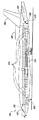
図1は、この発明の実施例に従って構成される航空機100を示す、部分的に図示されていないところのある、上面等角図である。この実施例の1つの局面では、航空機100は、胴体102と、胴体102から外側に向かって延びる翼110とを含む。胴体102は、第1の胴体部分104と、第1の胴体部分104の後方に位置付けられた第2の胴体部分106と、第2の胴体部分106の後方に位置付けられた第3の胴体部分108とを含み得る。翼110は、第2の胴体部分106に少なくとも隣接した胴体102に固定するように取付けられ得、前縁領域112および後縁領域115を含み得る。前縁領域112は、前縁117を含み得る。翼110はさらに、前縁117から胴体102に向かって前方に延びるインボードストレークまたは前縁延在部113を含み得る。
FIG. 1 is an isometric top view, partially unillustrated, illustrating an
この実施例の別の局面では、第1の胴体部分104は、第1の断面積114を有し得、第2の胴体部分106は、第1の断面積114よりも小さな第2の断面積116を有し得、第3の胴体部分108は、第2の断面積116よりも大きな第3の断面積118を有し得る。別の実施例では、胴体102は、他の形状を有し得る。たとえば、別の実施例では、第3の胴体部分108は、第2の胴体部分106の断面積に少なくともほぼ等しいか、またはそれよりも小さな断面積を有し得る。したがって、この別の実施例では、胴体102は、第1の胴体部分104から後方に向かって延びるにつれて細くなるテーパを有し得る。
In another aspect of this embodiment, the
この実施例のさらなる局面では、航空機100は、航空機100を約0.98以下の飛行マッハ数で推進させるように構成された推進システム120を含む。推進システム120は、エンジン124を収容するエンジンナセル122を含み得る。エンジンナセル122は、エンジン124の前方に位置付けられた空気入口126と、エンジン124の後方に位置付けられた排気ガス排出口128とを含み得る。この実施例のさらなる別の局面では、空気入口126は、翼110の前縁領域112の後方に位置付けられ、排気ガス排出口128は、後縁領域115の後方に位置付けられる。例示される実施例では、空気入口126は、翼110の前縁117の後方に位置付けられる。
In a further aspect of this embodiment,
他の実施例では、航空機100は、この発明の思想または範囲から逸脱することなく、他の推進システムを含み得る。たとえば、別の実施例では、航空機100は、翼110の後縁領域115の前方に位置付けられた排気ガス排出口を備えたエンジンナセルを有する推進システムを含み得る。代替的には、さらなる実施例では、航空機100は、翼110の前縁領域112の前方に位置付けられた空気入口を備えたエンジンナセルを有する推進システムを含み得る。さらなる他の実施例では、航空機100は、翼110と一体化され
ているか、または胴体102に取付けられたエンジンナセルを含み得る。
In other embodiments,
この実施例のさらなる別の局面では、胴体102は、機首部分105内に位置付けられたフライトデッキ103を含む。機首部分105は、それほど尖っておらず、たとえば、ほぼ音速または遷音速での飛行のための低い空力抵抗特性を提供しながら、パイロットのための申し分のない視界および効率的なフライトデッキレイアウトを提供し得る。
In yet another aspect of this embodiment,
図1に示されるこの発明の実施例の1つの特徴は、胴体102の形状および推進システム120の相対的な配置により、単調に変化する断面積分布等の、ほぼ平滑で、徐々に変化する断面積分布が航空機100に提供されることである。この特徴の1つの利点は、エリアルールに従うと、航空機100は、ほぼ音速では比較的低い遷音速造波抗力を生成することである。他の実施例では、外部フェアリングおよび/または他の構造的な要素が、胴体圧力容器の外側に取付けられて、単調に変化する断面積分布が航空機100に提供され得る。図1に示されるこの発明の実施例の別の特徴は、インボード前縁延在部113によって、翼の付け根付近の翼110の厚弦比が減じられることである。この特徴の利点は、空力抵抗が減じられ、翼の曲げ荷重がより低くなり、エリアルールが改良されることを含む。
One feature of the embodiment of the invention shown in FIG. 1 is that the shape of the
図2Aから図2Cはそれぞれ、この発明の実施例に従って構成される図1の航空機100の上面図、正面図、および側面図である。まず、図2Aを参照して、この実施例の1つの局面では、航空機100は、回動可能なように胴体102に取付けられるノーズギア232と、回動可能なように翼110に取付けられる(個別に、第1のメインギア230aおよび第2のメインギア230bとして識別される)メインギア230とを含む。メインギア230aおよび230bは、それぞれ、翼桁ボックス210aおよび210bと構造的に一体化され得、それぞれ、ホイールトラック231aおよび231bを含み得る。ホイールトラック231aおよび231bは、それぞれ、地面上で航空機100を支持するための静的展開位置234aおよび234bと、それぞれ、飛行中の空力抵抗を減じるための静的格納位置236aおよび236bとの間で移動可能であり得る。展開された静的位置234では、ホイールトラック231は、エンジン吸気口126の後方に位置付けられて、異物が見通し線(line-of-sight)方向にエンジンナセル124に吸込まれる可能性を少なくし得る。静的格納位置236では、ホイールトラック231aおよび231bはそれぞれ、図1の第2の胴体部分106の下部領域に位置付けられた脚室238aおよび238b内に収容され得る。この特徴の利点は、胴体102のより幅の広い部分を、貨物専用コンテナを運ぶために確保しておくことができることである。
2A-2C are top, front, and side views, respectively, of
次に図2Bを参照して、この実施例の1つの局面では、エンジン吸気口126は、翼110の下面212と一体化される。この特徴の1つの利点は、翼110下の流れ場の静圧が比較的高く、エンジン124に対する気流特性が改良されることである。この特徴のさらなる利点は、ナセル122と翼の下面212との間の空力的な相互作用によって、揚力の増大を含む、さらなる空力的な利益が航空機100に提供され得ることである。
Referring now to FIG. 2B, in one aspect of this embodiment, the
次に図2Cを参照して、この実施例の1つの局面では、胴体102は、(第1の人員用ドア202a、第2の人員用ドア202b、第3の人員用ドア202c、第4の人員用ドア202d、および第5の人員用ドア202eとして図示される)複数の人員用ドア202と、(第1の貨物用ドア204aおよび第2の貨物用ドア204bとして図示される)複数の貨物用ドア204を含む。一実施例では、人員用ドア202aおよび202eは、ギャレーサービスドアであり得、人員用ドア202c−eは、乗客用ドアであり得る。ギャレーサービスドア202aおよび202eは、胴体102の一方側にのみ位置付けられ得、乗客用ドア202b−dは、対になって、胴体102の両側に位置付けられ得る。胴体102の構成によって、翼110の前方、上方、および後方に、さまざまな人員用ドア
202を位置付けることができる。加えて、胴体102の構成によってさらに、翼110の前方および後方の両方での貨物用ドア204の位置付けが可能になる。他の実施例では、航空機100は、他の乗客用、乗務員用、サービス用、および貨物用のドアの位置および構成を含み得る。たとえば、別の実施例では、航空機100は、翼110の前方に追加的なギャレーサービスドアを含んでもよく、および/または、翼110の後方に追加的なギャレーサービスドアを含んでもよい。
Referring now to FIG. 2C, in one aspect of this embodiment, the
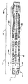
図3は、この発明の実施例に従って構成される胴体102の様子を例示する、航空機100を示す、部分的に図示されていないところのある側面図である。簡素化のため、図3からエンジンナセル122を取除いた。この実施例の1つの局面では、胴体102は、上部デッキ306および下部デッキ308を含む。下部デッキ308は、並べて位置付けられる、LD−2またはLD−3ユニットロードデバイス(ULD)等の複数の貨物専用コンテナ316を保持するように構成され得る。貨物専用コンテナ316は、下部デッキ308上で翼桁ボックス210の前後に長手方向に配置され得る。以下でより詳細に説明されるように、他の実施例では、下部デッキ308は、乗客、または、乗客および貨物を保持するように構成され得る。
FIG. 3 is a side view, partially unillustrated, showing the
この実施例のさらなる局面では、航空機100は、第3の胴体部分108の少なくとも付近から外側に向かって延びる垂直安定板360および水平安定板362を含む。水平安定板362は、垂直安定板360の後方で、長手方向において食い違い得る。この様態で垂直安定板360に対して水平安定板362を長手方向に食い違わせることによって、航空機100にエリアルールを適用してほぼ音速のマッハ数での航空機100の空力抵抗を減じるためのさらなるメカニズムが提供され得る。
In a further aspect of this embodiment,
この実施例の別の局面では、胴体102は、第3の胴体部分108に少なくとも隣接して位置付けられた任意の燃料タンク302を含む。胴体102のこの部分に任意の燃料タンク302を位置付けることによって、垂直安定板360の下で加圧されていない体積が効率的に用いられ得る。さらに、任意の燃料タンク302は、必要とされるC.G.限界を広くするために航空機100のC.G.位置を能動的に管理するための手段を提供し、航空機の空の重量を減じ、空力トリム抵抗を減じることができる。この実施例のさらなる局面では、航空機100は、第3の胴体部分108の少なくともほぼ後方に位置付けられる任意の電子および/または物理的テールスキッド370を含み得る。
In another aspect of this embodiment, the
図4は、この発明の実施例に従って構成される胴体102の上部デッキ306を示す、図3の線4−4に実質的に沿った上部断面図である。この実施例の1つの局面では、上部デッキ306は、第1の胴体部分104内に位置付けられるファーストクラスの座席部分401およびビジネスクラスの座席部分402と、第2の胴体部分106および第3の胴体部分108内に位置付けられるエコノミークラスの座席部分403とを備えた3つのクラスの内部構成を含む。ファーストクラスの座席部分401は、4つのファーストクラス座席404を有する座席列を含み、2席ずつの組が2つ配置され、各々の組が、中央の乗客用通路の両側にあり得る。ファーストクラス座席404は、2つ並んだときには、約57インチ幅であり得る。ビジネスクラスの座席部分402は、6つのビジネスクラス座席405を有する座席列を含み、2席ずつの組が3つ配置され、左側の乗客用通路と右側の乗客用通路とによって分けられ得る。ビジネスクラス座席405は、2つ並んだときには、約53インチ幅であり得る。エコノミークラスの座席部分403は、5つから7つのエコノミークラス座席406を有する座席列を含み、2席ずつの組が2つ外側に、1席から3席ずつの組が中央に、配置され、左右の乗客用通路によって分けられ得る。エコノミークラス座席406は、2つ並べられたときには、約43インチ幅であり得る。他の実施例では、上部デッキ306は、他の乗客用座席構成を有し得る。たとえば、別の実施例では、上部デッキ306は、単一の通路の乗客用座席構成を含み得る。
FIG. 4 is a top cross-sectional view taken substantially along line 4-4 of FIG. 3 showing the
図4に示されるこの発明の実施例の1つの特徴は、ファーストクラス座席部分401およびビジネスクラス座席部分402が、第1の胴体部分104内に位置付けられることである。この特徴の1つの利点は、第1の胴体部分104は、一般に、第2の胴体部分106よりも大きな断面積を有し、したがって、エコノミークラスの乗客よりも高い運賃を支払うファーストクラスの乗客およびビジネスクラスの乗客に対してさらなるスペースおよび快適さを提供することである。加えて、すべての窓側の座席が航空機の側壁に対して等しい大きさのスペースを提供する従来の航空機とは異なり、この発明の上部デッキ306は、湾曲し、さらにはエリアルールされた胴体102の形状を利用することによって、側壁にさらなるスペースを与える多くの窓側の座席を提供する。
One feature of the embodiment of the invention shown in FIG. 4 is that the first
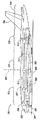
図5は、この発明の別の実施例に従って構成される多目的下部デッキ508を備える胴体502を有する航空機500を示す、部分的に図示されていないところのある、側面図である。この実施例の1つの局面では、胴体502は、第1の胴体部分510と、第1の胴体部分510の後方に位置付けられる第2の胴体部分520と、第2の胴体部分520の後方に位置付けられる第3の胴体部分530とを含む。航空機500はさらに、第2の胴体部分520に少なくとも隣接して位置付けられる翼550と、第3の胴体部分530の後方に位置付けられる尾翼部分540とを含み得る。尾翼部分540は、偏揺れ軸504に対して飛行中の航空機500の動きを制御するための垂直安定板542を含み得る。
FIG. 5 is a side view, partially not shown, showing an
この実施例の別の局面では、胴体502は、遷音速造波抗力を減じるようにエリアルールされる。たとえば、第1の胴体部分510は、偏揺れ軸504に対して少なくともほぼ平行な第1の寸法511を有し得、第2の胴体部分520は、偏揺れ軸504に対して少なくともほぼ平行であり、かつ第1の寸法511よりも小さい第2の寸法512を有し得、第3の胴体部分530は、偏揺れ軸504に対して少なくともほぼ平行であり、かつ第2の寸法512よりも大きな第3の寸法513を有し得る。
In another aspect of this embodiment,
この実施例のさらなる局面では、胴体502は、乗客(図示せず)を収容するように構成された第1の乗客用部分507を有する上部デッキ506を含む。上部デッキ506は、第1の胴体部分510、第2の胴体部分520、および第3の胴体部分530内に延在し得る。多目的下部デッキ508は、上部デッキ506の下で、少なくとも第1の胴体部分510内に延在し、乗客を収容するように構成された第2の乗客用部分509を含み得る。この実施例では、下部デッキ508は、有利なことには、エリアルールによる追加的なスペースを有する胴体502の部分に位置付けられる。
In a further aspect of this embodiment, the
この実施例のさらなる局面では、航空機500は、下部デッキ508の前方部分または下部デッキ508の後方部分に位置付けられる任意の乗務員用休憩エリア580を含み得る。別の実施例では、航空機500は、胴体502の断面積がエリアルールのために最も大きくなる上部デッキ506の前方または後方の客室上の最上部に、または上部デッキ506内に、任意の乗務員用休憩エリアを含み得る。
In a further aspect of this embodiment,
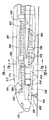
図6は、この発明の実施例に従って構成される下部デッキ508を示す第1の胴体部分510の、部分的に図示されていないところのある拡大側面図である。この実施例の1つの局面では、下部デッキ508は、第2の乗客用部分509の前方に位置付けられる貨物用部分614をさらに含む。貨物用部分614は、LD−2またはLD−3 ULD等の貨物専用コンテナ616および/または他のパレット貨物を保持するように構成され得る。第1の胴体部分510は、貨物専用コンテナ616を貨物用部分614に対して出し入れするための、貨物用部分614の付近に位置付けられる貨物用ドア618を含み得る。
FIG. 6 is an enlarged side view, partially unillustrated, of
この実施例の別の局面では、下部デッキ508は、貨物用部分614と第2の乗客用部
分509との間に延在する区切り620をさらに含む。区切り620は、貨物用部分614と第2の乗客用部分509との間にバリアを提供する、剛性またはやや剛性の構造であり得る。他の実施例では、区切り620は、貨物用ネット等の可撓性のある構造であり得る。この実施例のさらなる局面では、区切り620は、下部デッキ508のさまざまな長手方向の場所で、選択的に配置可能である。このようにして、貨物用部分614および第2の乗客用部分509の相対的なサイズは、貨物および乗客を乗せるさまざまな場面に対応するように調整され得る。他の実施例では、区切り620の長手方向の場所は、少なくともほぼ調整不可能であり得る。
In another aspect of this embodiment,
この実施例のさらなる局面では、第1の胴体部分510は、上部デッキ506付近に位置付けられる第1の乗客用窓列650と、下部デッキ508付近に位置付けられる第2の乗客用窓列652とを含む。第2の乗客用窓列652は、翼550によってブロックされるため、第2の乗客用部分509と比べると、部分的にしか後方に延在しない。第2の乗客用部分509の後方部分に着席する乗客に対して航空機の外の景色を提供するために、第1の胴体部分510は、翼550付近で、第2の乗客用窓列652から後方に向かって延びる、シミュレートされた外の景色の窓列654を含み得る。シミュレートされた外の景色の窓654は、ビデオディスプレイ等の「バーチャルウィンドウ技術」を含み得、これは、従来の外の景色の窓をシミュレートし、さらには翼550付近に着席した乗客に対して、シミュレートされた、第2の乗客用部分509の外の景色を提供する。他の実施例では、シミュレートされた外の景色の窓654は、省略され得る。
In a further aspect of this embodiment, the
この実施例のさらなる局面では、第1の胴体部分510は、上部デッキ506と下部デッキ508との間で延びて、第1の乗客用部分507と第2の乗客用部分509との間での乗客の移動に対応する階段622を含む。他の実施例では、第1の胴体部分510は、上部デッキ506と下部デッキ508との間での乗客の移動のために、別の種類の通路を含み得る。たとえば、別の実施例では、第1の胴体部分510は、エレベータを含み得る。さらなる実施例では、第1の胴体部分は、エスカレータまたは梯子を含み得る。
In a further aspect of this embodiment, the
この実施例のさらなる別の局面では、第1の胴体部分510は、下部デッキ508の前方に位置付けられる脚室666内に収容される後方引込式着陸装置660を含む。離陸後、着陸装置660は、トラニオン662を中心にして後方および上方に回動して、ホイールトラック664を(図6に示される)静的展開位置から脚室666内の静的格納位置に移動させ得る。脚室666の前方部分にトラニオン662を位置付けることによって、着陸装置の折り畳みの際に、着陸装置660が折り畳まれて脚室666内に入ることとなり、したがって、下部デッキ508の損傷が妨げられる。しかしながら、他の実施例では、着陸装置660は、他の方向に引込まれ得る。たとえば、別の実施例では、着陸装置660は、前方に引込まれて、適切に構成された脚室内に入り得る。さらなる実施例では、着陸装置660は、横方向に引込まれて、適切に構成された脚室内に入り得る。
In yet another aspect of this embodiment, the
図5および図6に示されるこの発明の実施例の1つの特徴は、第1の胴体部分510が、第2の乗客用部分509を収容するための追加的な断面スペースを必要とすることである。この特徴の1つの利点は、追加的な断面スペースを利用して、エリアルールに従った遷音速での造波抗力を減じるためのほぼ平滑で、かつ緩やかな断面積分布を航空機500に提供できることである。
One feature of the embodiment of the invention shown in FIGS. 5 and 6 is that the
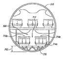
図7Aおよび図7Bはそれぞれ、図6の線7A−7Aおよび7B−7Bに実質的に沿った第1の胴体部分510の拡大断面図である。まず、図7Aを参照して、この実施例の1つの局面では、第2の乗客用部分509は、中央の乗客用通路712の両側に位置付けられる第1の乗客用座席部分710aおよび第2の乗客用座席部分710bを含む。例示される実施例では、各乗客用座席部分710は、3つ並んだ乗客用の座席構成を含む。他の
実施例では、第2の乗客用部分509は、他の乗客用座席構成を含み得る。たとえば、別の実施例では、乗客用通路712は、中央からずれて位置付けられてもよく、第2の乗客用部分509は、乗客用通路712の一方側では、2つ並んだ乗客用の座席を含み、他方側では、4つ並んだ乗客用座席を含み得る。さらなる実施例では、第2の乗客用部分509は、3つの乗客用座席部分を分ける2つの乗客用通路を含み得る。このさらなる実施例では、各乗客用座席部分は、2つ並んだ乗客用座席構成を含み得る。さらに他の実施例では、第2の乗客用部分509は、胴体、通路、および/または座席の幅等の要因に応じて、さらに他の乗客用座席構成を含み得る。
7A and 7B are enlarged cross-sectional views of the
この実施例の別の局面では、第2の乗客用部分509は、エネルギ吸収構造770の上方に位置付けられる第1の床714aを含む。エネルギ吸収構造770は、第1の胴体部分510の底部への衝撃からのエネルギを吸収するように構成され得る。このような衝撃は、たとえば、緊急着陸の最中に起こり得る。第1の床714aは、距離762だけ、第1の胴体部分510の底部から間隔をあけられ得る。この実施例のさらなる局面では、距離762は、約30インチに等しくなり得る。他の実施例では、距離762は、他の値を有し得る。たとえば、別の実施例では、距離762は、約36インチであり得る。さらなる実施例では、距離762は、約24インチであり得る。さらなる他の実施例では、距離762は、エネルギ吸収構造770のエネルギ吸収能力または該当する規則の要件等の要因に応じて、さらに他の値を有し得る。
In another aspect of this embodiment,
次に、図7Bを参照して、この実施例の1つの局面では、貨物用部分614は、LD−3貨物専用コンテナ716aおよび716b等の貨物専用コンテナを並んだ配置で保持するように構成されている。他の実施例では、貨物用部分614は、他の種類のコンテナ貨物を保持するように構成され得る。たとえば、別の実施例では、貨物用部分614は、2つ並んだ、または他の構成で、LD−2またはLD−1貨物専用コンテナを保持するように構成され得る。さらなる実施例では、貨物用部分614は、パレット貨物、または、パレット貨物および標準のULDを保持するように構成され得る。
7B, in one aspect of this embodiment, the
この実施例のさらなる局面では、貨物用部分614は、第1の床714aの上方に位置付けられる第2の床714bを含んで、必要であれば、貨物専用コンテナ716aおよび716bを収容し得る。第2の床714bは、取外し可能なように下部デッキ508中に備え付けられたフロアインサート718を含み得る。したがって、取外し可能なフロアインサート718および移動可能な区切り620(図6)を用いることによって、さまざまな比率で貨物および乗客を、または、貨物、乗客を運べるように、下部デッキ508が選択的に構成され得る。
In a further aspect of this embodiment, the
図8は、この発明の実施例に従って構成される着陸装置支持アセンブリ830を図示した、航空機100の一部を示す、図2Aからの上面切開図である。この実施例の1つの局面では、着陸装置支持アセンブリ830は、後方翼桁806に固定するように取付けられる前方トラニオン支持部838と、前方トラニオン支持部838のアウトボードで後方翼桁806に少なくとも隣接して取付けられる後方トラニオン支持梁832とを含む。後方トラニオン支持梁832は、後方翼桁806から少なくともほぼ後方に延び、軸814に沿って前方トラニオン支持部838と軸方向に整合する後方トラニオン支持部834を含む。他の実施例では、後方トラニオン支持梁832は、前方トラニオン支持部838のインボードで後方翼桁806に取付けられ得る。
FIG. 8 is a top cut-away view from FIG. 2A showing a portion of the
以下でより詳細に説明されるように、着陸装置の主支柱812が、前方トラニオン支持部838と後方トラニオン支持部834とに回動可能なように取付けられて、図8に示されるような静的展開位置と、胴体102に向かって内側に折り畳まれる静的格納位置との間で、軸814を中心として回動するように動き得る。静的展開位置と静的格納位置との
間で着陸装置の主支柱を回動可能なように動かすために通例用いられる周知の構造およびシステムは、簡素化のために、図8では図示されない。静的展開位置では、主支柱812は、ホイールトラック(図示せず)を翼110の下に位置付けて、移動可能なように航空機100を地面上で支持し得る。一旦、飛行が始まると、主支柱812は、軸814を中心にして内側に引込まれて、飛行のために、ホイールトラックを対応する脚室238(図2A)内に収容し得る。
As will be described in more detail below, the landing gear
この実施例の別の局面では、着陸装置支持アセンブリ830は、インボード横支持支柱840と、(第1のアウトボード横支持支柱842aおよび第2のアウトボード横支持支柱842bとして示される)アウトボード横支持支柱842とを含む。アウトボード横支持支柱842は、後方翼桁806から後方トラニオン支持部834の少なくとも付近にまで延び得る。インボード横支持支柱840も同様に、胴体102から後方トラニオン支持部834の少なくとも付近にまで延び得る。
In another aspect of this embodiment, the landing
この実施例のさらなる局面では、インボード横支持支柱840およびアウトボード横支持支柱842はそれぞれ、主支柱812からのサイド荷重を胴体102および後方翼桁806へと移し得る。後方トラニオン支持梁832は、主支柱812からの垂直方向の荷重を後方翼桁806に移し得る。他の実施例では、他の構造的構成が用いられて、主支柱812からの荷重が翼110および/または胴体102に移され得る。たとえば、別の実施例では、インボード横支持支柱840が省かれ得、アウトボード横支持支柱842が、主支柱812からのサイド荷重を後方翼桁806に移し得る。さらに別の実施例では、アウトボード横支持支柱842が省かれ得、インボード横支持支柱840が、主支柱812からのサイド荷重を胴体102に移し得る。
In a further aspect of this embodiment, inboard lateral support struts 840 and outboard lateral support struts 842 can transfer side loads from
図9は、図8の着陸装置支持アセンブリ830を示す、拡大された上面後方等角図である。インボード横支持支柱840(図8)は、簡素化のために取除かれた。この実施例の1つの局面では、後方トラニオン支持梁832は、後方翼桁806の少なくとも付近に取付けられるように構成されたベース部分932と、ベース部分932から後方トラニオン支持部834に向かって延びるねじりの中心軸950とを含む。この用語「ねじりの中心軸」は、後方トラニオン支持梁832の軸であって、そこを通して、外力が、ねじり荷重を後方トラニオン支持梁832に導入することなく、作用することのできる、後方トラニオン支持梁832の軸を表わすためにここで用いられている。つまり、ねじりの中心軸950と交わる作用線を有する外力の結果として、後方トラニオン支持梁832の変位が得られるだけであり、ねじれは生じ得ない。
FIG. 9 is an enlarged top rear isometric view showing the landing
この実施例の別の局面では、後方トラニオン支持部834は、ベース部分932から間隔をあけられており、ピン966を受けて主支柱812の後方回動部分912aを回動可能なように支持するように構成される。主支柱812が、図9に示されるような静的展開位置にある場合、後方回動部分912aは、合力を作用線952に沿って後方トラニオン支持部834に対して及ぼす。後方トラニオン支持部834およびねじりの中心軸950は、作用線952と少なくともほぼ整合され得る。結果として、主支柱812の後方回動部分912aが、合力を作用線952に沿って後方トラニオン支持部834に及ぼすとき、作用線952は、ねじりの中心軸950と少なくともほぼ交わる。作用線952とねじりの中心軸950との間のいずれかのオフセットを減じることによって、または解消することによって、後方トラニオン支持梁832上のねじり荷重が減じられ得るか、または解消され得る。このねじり荷重の減少によって、後方トラニオン支持梁832のサイズおよび重量が同様に減じられ得る。
In another aspect of this embodiment, the
例示される実施例では、ねじりの中心軸950および後方トラニオン支持部834を作用線952と整合させることによって、結果として、後方トラニオン支持部834が、ね
じりの中心軸950と少なくともほぼ垂直に整合される。他の実施例では、この整合を維持することによって、後方トラニオン支持部834が、展開静的位置での主支柱812の角度に応じて、ねじりの中心軸950に対して横方向にオフセットにされ得る。
In the illustrated embodiment, aligning the central axis of
この実施例のさらなる局面では、ベース部分932は、第1のヒューズピン960aおよび第2のヒューズピン960bを用いて後方翼桁806に取付けられ、これらの両方が、互いと垂直方向に整合して位置付けられる。この実施例のさらに別の局面では、主支柱812の前方回動部分912bが、第3のヒューズピン960cによって前方トラニオン支持部838に回動可能なように取付けられ、アウトボード横支持支柱842aおよび842bはそれぞれ、第4のヒューズピン960dおよび第5のヒューズピン960eによって後方翼桁806に取付けられる。したがって、主支柱812が、過度の、または破壊的な着陸力等の予め選択された力を作用線952に沿って後方トラニオン支持部834に及ぼす場合、結果として得られる、後方トラニオン支持梁832上の曲げ荷重は、ヒューズピン960aおよび960b、続いて、ヒューズピン960c−eを破壊させ、それらに、後方トラニオン支持梁832、主支柱812、およびアウトボード横支持支柱842を後方翼桁806から取外させる。この様態でこれらの構成要素を後方翼桁806から取外すことによって、それらが、後方翼桁806を破壊することが妨げられ、さらには、着陸装置支持アセンブリ830付近の後方翼桁806の反対側に位置付けられる燃料タンク907の漏れを引起こすことが妨げられる。
In a further aspect of this embodiment, the
他の実施例では、他の要素を用いて、上述のものと同様の壊して外す能力を着陸装置支持アセンブリ830に提供することができる。たとえば、別の実施例では、(たとえば、ヒューズピンではない)高強度のピンまたはボルトを用いて、後方トラニオン支持梁832および着陸装置支持アセンブリ830の他の構成要素を後方翼桁806に取付けることができる。この実施例では、後方トラニオン支持梁832の一部分および他の構成要素の同様の部分は、後方トラニオン支持梁832が過度の着陸力を経験した場合に壊れるように、標準より小さくされ得るか、または、他の様態で構成され得る。
In other embodiments, other elements can be used to provide the landing
図9に示されるこの発明の実施例の1つの特徴は、主支柱812が静的展開位置にあるとき、作用線952をねじりの中心軸950と少なくともほぼ交わらせるように、後方トラニオン支持部834が位置付けられていることである。この特徴の利点は、後方トラニオン支持梁832が、かなりのねじり荷重を支えるような大きさにされる必要がなく、したがって、その重量が減じられ得ることである。図9に示されるこの発明の実施例の別の特徴は、ヒューズピン960a−eの配置によって、後方トラニオン支持部834が後方トラニオン支持梁832の少なくともほぼ下に位置付けられることが可能となり、同時に、着陸装置支持アセンブリ830に対して上述のような壊れて外す能力が提供されることである。この特徴の利点は、大惨事になり得る着陸状態が、燃料タンクの破裂によってさらに悪化する可能性がなくなることである。
One feature of the embodiment of the present invention shown in FIG. 9 is that the
以上のことから、この発明の具体的な実施例は、例示の目的のためにここで示されており、この発明の思想および範囲から逸脱することなく、さまざまな変形例が作成され得ることが理解されるであろう。したがって、この発明は、添付の請求項によってのみ限定される。 From the foregoing, specific embodiments of the present invention have been presented herein for purposes of illustration, and various modifications may be made without departing from the spirit and scope of the invention. Will be appreciated. Accordingly, the invention is not limited except as by the appended claims.
100、500 航空機、102、502 胴体、104、510 第1の胴体部分、106、520 第2の胴体部分、108、530 第3の胴体部分、114 第1の断面積、116 第2の断面積、118 第3の断面積、110、550 翼、112 前縁領域、115 後縁領域、120 推進システム、126 空気入口、511 第1の寸法、512 第2の寸法、513 第3の寸法、128 排気ガス排出口、710 乗客用座席。 100, 500 aircraft, 102, 502 fuselage, 104, 510 first fuselage part, 106, 520 second fuselage part, 108, 530 third fuselage part, 114 first cross-sectional area, 116 second cross-sectional area , 118 third cross-sectional area, 110, 550 wing, 112 leading edge region, 115 trailing edge region, 120 propulsion system, 126 air inlet, 511 first dimension, 512 second dimension, 513 third dimension, 128 Exhaust exhaust, 710 passenger seat.
Claims (34)
胴体を含み、前記胴体は、
第1の断面積を備えた第1の胴体部分と、
前記第1の胴体部分の後方に位置付けられる第2の胴体部分とを有し、前記第2の胴体部分は、前記第1の断面積よりも小さな第2の断面積を有し、前記胴体はさらに、
前記第2の胴体部分の後方に位置付けられる第3の胴体部分を有し、前記第3の胴体部分は、前記第2の断面積よりも大きな第3の断面積を有し、前記航空機はさらに、
前記胴体に固定して取付けられ、さらには前記第2の胴体部分に少なくとも隣接する位置から外側に向かって延びる翼を含み、前記翼は、前縁領域を有し、前記航空機はさらに、
前記翼に固定して取付けられる推進システムを含み、前記推進システムは、前記翼の前記前縁領域の後方に位置付けられる空気入口を有する、航空機。 An aircraft,
Including a torso, wherein the torso is
A first body portion having a first cross-sectional area;
A second torso portion positioned behind the first torso portion, wherein the second torso portion has a second cross-sectional area smaller than the first cross-sectional area; further,
A third fuselage portion positioned behind the second fuselage portion, wherein the third fuselage portion has a third cross-sectional area that is greater than the second cross-sectional area; ,
The aircraft further includes a wing fixedly attached to the fuselage and extending outwardly from a location at least adjacent to the second fuselage portion, the wing having a leading edge region, the aircraft further comprising:
An aircraft, comprising a propulsion system fixedly attached to the wing, the propulsion system having an air inlet positioned behind the leading edge region of the wing.
前記推進システムは、前記翼の前記後縁領域の後方に位置付けられる排気ガス排出口をさらに含む、請求項1に記載の航空機。 The wing further includes a trailing edge region;
The aircraft of claim 1, wherein the propulsion system further comprises an exhaust outlet located behind the trailing edge region of the wing.
前記ホイールトラックの前記静的展開位置は、前記空気入口の後方にある、請求項1に記載の航空機。 The landing gear further includes a landing gear rotatably mounted on the wing, the landing gear reducing the aerodynamic drag in flight and a static deployment position for supporting the aircraft on the ground so as to be movable. Including a wheel track movable to and from a static storage position for
The aircraft of claim 1, wherein the static deployed position of the wheel track is behind the air inlet.
前記翼は、インボード前縁をさらに含み、前記インボード前縁は、前記アウトボード前縁から前方に延びて前記胴体に対して第2の後退角を少なくともほぼ規定し、前記第2の後退角は、前記第1の後退角よりも高い、請求項1に記載の航空機。 The leading edge region of the wing includes an outboard leading edge defining a first sweepback angle with respect to the fuselage;
The wing further includes an inboard leading edge, the inboard leading edge extending forward from the outboard leading edge to at least approximately define a second retraction angle with respect to the fuselage, The aircraft of claim 1, wherein an angle is higher than the first sweepback angle.
前記推進システムの前記空気入口は、前記翼の前縁の後方に位置付けられる、請求項1に記載の航空機。 The leading edge region of the wing includes a leading edge of the wing;
The aircraft of claim 1, wherein the air inlet of the propulsion system is located behind a leading edge of the wing.
前記第3の胴体部分から外側に向かって延びる水平安定板とをさらに含み、前記水平安
定板は、前記垂直安定板の少なくともほぼ後方に位置付けられる、請求項1に記載の航空機。 A vertical stabilizer extending outwardly from the third body portion;
The aircraft of claim 1, further comprising a horizontal stabilizer extending outwardly from the third fuselage portion, wherein the horizontal stabilizer is positioned at least substantially behind the vertical stabilizer.
前記航空機は、前記翼の後縁領域の後方の前記第3の胴体部分の少なくともほぼ内側に位置付けられる燃料タンク部分をさらに含む、請求項1に記載の航空機。 The wing further includes a trailing edge region;
The aircraft of claim 1, wherein the aircraft further comprises a fuel tank portion located at least substantially inside the third fuselage portion behind the wing trailing edge region.
前記垂直安定板に隣接した前記第3の胴体部分の少なくともほぼ内側に位置付けられる燃料タンク部分とをさらに含む、請求項1に記載の航空機。 A vertical stabilizer extending outwardly from the third body portion;
The aircraft of claim 1, further comprising a fuel tank portion positioned at least substantially inside the third fuselage portion adjacent the vertical stabilizer.
胴体を含み、前記胴体は、
前記航空機の長手方向の軸を横断する第1の最大寸法を有する第1の胴体部分と、
前記第1の胴体部分の後方に位置付けられる第2の胴体部分とを含み、前記第2の胴体部分は、前記航空機の前記長手方向の軸を横断する第2の最大寸法を有し、前記第2の最大寸法は、前記第1の最大寸法よりも小さく、前記胴体はさらに、
前記第2の胴体部分の後方に位置付けられる第3の胴体部分を含み、前記第3の胴体部分は、前記航空機の前記長手方向の軸を横断する第3の最大寸法を有し、前記第3の最大寸法は、前記第2の最大寸法よりも大きく、前記航空機はさらに、
前記胴体に固定して取付けられ、さらには前記第2の胴体部分に少なくとも隣接する位置から外側に向かって延びる翼を含み、前記翼は、前縁領域を有し、前記航空機はさらに、
前記翼に固定して取付けられる推進システムを含み、前記推進システムは、前記翼の前記前縁領域の後方に位置付けられる空気入口を有する、航空機。 An aircraft,
Including a torso, wherein the torso is
A first fuselage portion having a first maximum dimension transverse to a longitudinal axis of the aircraft;
A second fuselage portion positioned aft of the first fuselage portion, the second fuselage portion having a second largest dimension transverse to the longitudinal axis of the aircraft, 2, the maximum dimension is smaller than the first maximum dimension, and the body further comprises:
A third fuselage portion positioned aft of the second fuselage portion, the third fuselage portion having a third largest dimension transverse to the longitudinal axis of the aircraft; Is greater than the second largest dimension, and the aircraft further comprises:
The aircraft further includes a wing fixedly attached to the fuselage and extending outwardly from a location at least adjacent to the second fuselage portion, the wing having a leading edge region, the aircraft further comprising:
An aircraft, comprising a propulsion system fixedly attached to the wing, the propulsion system having an air inlet positioned behind the leading edge region of the wing.
前記第2の胴体部分は、前記第2の胴体部分において横方向に位置付けられる少なくとも5つの乗客用座席を収容することができる、請求項14に記載の航空機。 The first torso portion can accommodate at least six passenger seats positioned laterally in the first torso portion;
15. The aircraft of claim 14, wherein the second fuselage portion can accommodate at least five passenger seats positioned laterally on the second fuselage portion.
前記第1の乗客用デッキの下に位置付けられる第2の乗客用デッキとをさらに含む、請求項14に記載の航空機。 A first passenger deck extending at least inside the first torso portion, the second torso portion, and the third torso portion;
15. The aircraft of claim 14, further comprising a second passenger deck positioned below the first passenger deck.
側に延在する乗客用デッキと、
前記乗客用デッキの下に位置付けられる第2のデッキとをさらに含み、前記第2のデッキは、少なくとも2つのLD−3貨物専用コンテナを保持するように構成される、請求項14に記載の航空機。 A passenger deck extending at least inside the first torso portion, the second torso portion, and the third torso portion;
15. The aircraft of claim 14, further comprising a second deck positioned below the passenger deck, wherein the second deck is configured to hold at least two LD-3 cargo-only containers. .
前記推進システムの前記空気入口は、前記翼の前縁の後方に位置付けられる、請求項14に記載の航空機。 The leading edge region of the wing includes a leading edge of the wing;
15. The aircraft of claim 14, wherein the air inlet of the propulsion system is located behind a leading edge of the wing.
胴体を含み、前記胴体は、
第1の胴体部分において横方向に位置付けられる少なくとも6つの乗客用座席を収容するように構成された第1の断面積を備えた第1の胴体部分と、
前記第1の胴体部分の後方に位置付けられる第2の胴体部分とを有し、前記第2の胴体部分は、前記第2の胴体部分において横方向に位置付けられる少なくとも5つの乗客用座席を収容するように構成され、さらには前記第1の断面積よりも小さい第2の断面積を有し、前記胴体はさらに、
前記第2の胴体部分の後方に位置付けられる第3の胴体部分を有し、前記第3の胴体部分は、前記第3の胴体部分において横方向に位置付けられる少なくとも6つの乗客用座席を収容するように構成され、さらには前記第2の断面積よりも大きな第3の断面積を有し、前記輸送機はさらに、
ほぼ音速の対気速度で効率的に動作するように構成された翼を含み、前記翼は、前記胴体に固定して取付けられ、前記第2の胴体部分に少なくとも隣接する位置から外側に向かって延び、前記翼は、前縁領域および後縁領域を有し、前記輸送機はさらに、
前記翼に固定して取り付けられる推進システムを含み、前記推進システムは、前記翼の前記前縁領域の後方に位置付けられる空気入口を有し、前記推進システムは、前記翼の前記後縁領域の後方に位置付けられる排気ガス排出口をさらに有する、輸送機。 A transport aircraft,
Including a torso, wherein the torso is
A first torso portion having a first cross-sectional area configured to accommodate at least six passenger seats positioned laterally in the first torso portion;
A second torso portion positioned behind the first torso portion, the second torso portion housing at least five passenger seats positioned laterally in the second torso portion. And further having a second cross-sectional area smaller than the first cross-sectional area, the body further comprises:
A third torso portion positioned behind the second torso portion, wherein the third torso portion accommodates at least six passenger seats positioned laterally in the third torso portion; And further having a third cross-sectional area larger than the second cross-sectional area, the transporter further comprises:
Wings configured to operate efficiently at substantially sonic airspeed, wherein the wings are fixedly attached to the fuselage and outwardly from a position at least adjacent to the second fuselage portion. Extending, the wing has a leading edge region and a trailing edge region, and the transport aircraft further comprises:
A propulsion system fixedly attached to the wing, the propulsion system having an air inlet positioned behind the leading edge region of the wing, wherein the propulsion system is positioned behind the trailing edge region of the wing. A transport aircraft further comprising an exhaust gas outlet positioned at:
前記第2の胴体部分は、前記航空機の前記長手方向の軸を横断する第2の最大寸法を有し、前記第2の最大寸法は、前記第1の最大寸法よりも小さく、
前記第3の胴体部分は、前記航空機の前記長手方向の軸を横断する第3の最大寸法を有し、前記第3の最大寸法は、前記第2の最大寸法よりも大きい、請求項23に記載の輸送機。 The first fuselage portion has a first largest dimension transverse to a longitudinal axis of the aircraft;
The second fuselage portion has a second maximum dimension transverse to the longitudinal axis of the aircraft, wherein the second maximum dimension is less than the first maximum dimension;
24. The method of claim 23, wherein the third fuselage portion has a third largest dimension transverse to the longitudinal axis of the aircraft, wherein the third largest dimension is greater than the second largest dimension. Transport aircraft as described.
前記第1の乗客用デッキの下に位置付けられ、さらには前記第1の胴体部分の少なくとも内側に延在する第2の乗客用デッキとをさらに含む、請求項23に記載の輸送機。 A first passenger deck extending at least inside the first torso portion, the second torso portion, and the third torso portion;
24. The transport aircraft of claim 23, further comprising a second passenger deck positioned below the first passenger deck and further extending at least inside the first fuselage portion.
前記翼桁ボックスの少なくともほぼ後方で前記翼に回動可能なように取付けられる着陸
装置をさらに含み、
前記着陸装置は、移動可能なように前記航空機を地面上で支持するための静的展開位置と、飛行中の空力抵抗を減じるための静的格納位置との間で移動できるホイールトラックを含み、
前記ホイールトラックの前記静的展開位置は、前記空気入口の後方にある、請求項23に記載の輸送機。 The wing further includes a spar box,
A landing gear pivotally mounted to the wing at least substantially behind the spar box;
The landing gear includes a wheel track movable between a static deployment position to movably support the aircraft on the ground and a static storage position to reduce aerodynamic drag during flight;
24. The transport aircraft of claim 23, wherein the static deployed position of the wheel truck is behind the air inlet.
前記翼桁ボックスの少なくともほぼ後方で前記翼に回動可能なように取付けられる着陸装置をさらに含み、
前記着陸装置は、移動可能なように前記航空機を地面上で支持するための静的展開位置と、飛行中の空力抵抗を減じるための静的格納位置との間で移動できるホイールトラックを含み、
前記ホイールトラックは、前記ホイールトラックが前記静的格納位置にあるとき、前記第2の胴体部分の少なくともほぼ中に位置付けられる脚室内に格納される、請求項23に記載の輸送機。 The wing further includes a spar box,
A landing gear pivotally mounted to the wing at least substantially behind the spar box;
The landing gear includes a wheel track movable between a static deployment position to movably support the aircraft on the ground and a static storage position to reduce aerodynamic drag during flight;
24. The transport vehicle of claim 23, wherein the wheel track is stored in a legroom located at least approximately within the second fuselage portion when the wheel track is in the static storage position.
第1の断面積を有する第1の胴体部分を提供するステップと、
前記第1の胴体部分の後方で、第2の胴体部分を前記第1の胴体部分に取付けるステップとを含み、前記第2の胴体部分は、前記第1の断面積よりも小さな第2の断面積を有し、前記方法はさらに、
前記第2の胴体部分の後方で、第3の胴体部分を前記第2の胴体部分に取付けるステップを含み、前記第3の胴体部分は、前記第2の断面積よりも大きな第3の断面積を有し、前記方法はさらに、
前記第2の胴体部分に少なくとも隣接して翼を取付けるステップを含み、前記翼は、前縁領域を有し、さらには前記第2の胴体部分から少なくともほぼ外側に向かって延び、前記方法はさらに、
推進システムを前記翼に取付けるステップを含み、前記推進システムは、前記翼の前記前縁領域の後方に位置付けられる空気入口を有する、航空機を製造するための方法。 A method for manufacturing an aircraft, the method comprising:
Providing a first body portion having a first cross-sectional area;
Attaching a second torso portion to the first torso portion behind the first torso portion, wherein the second torso portion has a second cross section smaller than the first cross-sectional area. And the method further comprises:
Attaching a third torso portion to the second torso portion behind the second torso portion, the third torso portion having a third cross-sectional area greater than the second cross-sectional area And the method further comprises:
Mounting the wing at least adjacent to the second fuselage portion, the wing having a leading edge region, and further extending at least approximately outwardly from the second fuselage portion, the method further comprising: ,
A method for manufacturing an aircraft, comprising attaching a propulsion system to the wing, the propulsion system having an air inlet positioned behind the leading edge region of the wing.
推進システムを前記翼に取付けるステップは、前記推進システムの前記空気入口を前記翼の前縁の後方に位置付けるステップを含む、請求項29に記載の方法。 The leading edge region of the wing includes a leading edge of the wing;
30. The method of claim 29, wherein attaching a propulsion system to the wing comprises positioning the air inlet of the propulsion system behind a leading edge of the wing.
推進システムを前記翼に取付けるステップは、前記翼の前記後縁領域の後方に排気ガス排出口を位置付けるステップを含む、請求項29に記載の方法。 The wing further includes a trailing edge region;
30. The method of claim 29, wherein attaching a propulsion system to the wing comprises locating an exhaust outlet behind the trailing edge region of the wing.
前記第3の胴体部分に少なくとも隣接した前記胴体に第2の安定板面を取付けるステップとをさらに含み、前記第1の安定板面は、第1の場所で前記胴体から外側に向かって延び、前記第2の安定板面は、前記第1の場所から長手方向にずれた第2の場所で前記胴体から外側に向かって延びる、請求項29に記載の方法。 Attaching a first stabilizer surface to the body at least adjacent to the third body portion;
Attaching a second stabilizer surface to the body at least adjacent to the third body portion, wherein the first stabilizer surface extends outwardly from the body at a first location; 30. The method of claim 29, wherein the second stabilizer surface extends outwardly from the fuselage at a second location longitudinally offset from the first location.
前記垂直安定板に隣接する前記第3の胴体部分の少なくともほぼ内側に燃料タンク部分を位置付けるステップとをさらに含む、請求項29に記載の方法。 Attaching a vertical stabilizer to the torso at least adjacent to the third torso portion;
Positioning a fuel tank portion at least approximately inside the third fuselage portion adjacent the vertical stabilizer.
Applications Claiming Priority (3)
| Application Number | Priority Date | Filing Date | Title |
|---|---|---|---|
| US41788502P | 2002-10-10 | 2002-10-10 | |
| US10/278,717 US6772977B2 (en) | 2002-10-10 | 2002-10-22 | Aircraft with multipurpose lower decks and associated methods of manufacture |
| US10/278,633 US6679452B1 (en) | 2002-10-10 | 2002-10-22 | Aircraft landing gear support assemblies and associated methods of installation |
Publications (1)
| Publication Number | Publication Date |
|---|---|
| JP2004276900A true JP2004276900A (en) | 2004-10-07 |
Family
ID=50190124
Family Applications (1)
| Application Number | Title | Priority Date | Filing Date |
|---|---|---|---|
| JP2003350979A Pending JP2004276900A (en) | 2002-10-10 | 2003-10-09 | Aircraft, transport aircraft, and manufacturing method for aircraft |
Country Status (3)
| Country | Link |
|---|---|
| EP (1) | EP1407963B2 (en) |
| JP (1) | JP2004276900A (en) |
| DE (1) | DE60311933T3 (en) |
Cited By (7)
| Publication number | Priority date | Publication date | Assignee | Title |
|---|---|---|---|---|
| JP2009012686A (en) * | 2007-07-06 | 2009-01-22 | Japan Aerospace Exploration Agency | Supersonic type aircraft configuration for reduction of rear end sonic boom |
| JP2009509850A (en) * | 2005-09-30 | 2009-03-12 | エアバス フランス | A device for controlling the swirl flow generated by an elliptical element on the bearing surface of an aircraft. |
| JP2010504881A (en) * | 2006-09-29 | 2010-02-18 | エアバス | Aircraft comprising a fuselage having a floor extending in a longitudinal section of the fuselage |
| JP2010514616A (en) * | 2006-12-26 | 2010-05-06 | エアバス | Aircraft fuselage |
| JP2015040039A (en) * | 2013-08-22 | 2015-03-02 | ザ・ボーイング・カンパニーTheBoeing Company | Aircraft with aft split-level multi-deck fuselage |
| KR20160005970A (en) | 2014-07-08 | 2016-01-18 | (주) 한림기연 | Rope for aquaculture and method of manufacturing thereof |
| JP2017516716A (en) * | 2014-05-30 | 2017-06-22 | ゾディアック エアロスペース | Lower deck commercial room |
Families Citing this family (6)
| Publication number | Priority date | Publication date | Assignee | Title |
|---|---|---|---|---|
| DE102006016756A1 (en) * | 2006-04-10 | 2007-10-11 | Airbus Deutschland Gmbh | Aircraft fuselage has two exterior skin regions comprising circular-arc-shaped contour of uniform curvature, along longitudinal direction of aircraft passenger cabin |
| CA2644964A1 (en) * | 2006-04-10 | 2007-10-18 | Airbus Deutschland Gmbh | Aircraft fuselage with circular-arc-shaped exterior contour |
| GB0716675D0 (en) | 2007-08-29 | 2007-10-03 | Airbus Uk Ltd | Aircraft landing gear assembly |
| RU2462395C2 (en) * | 2010-12-09 | 2012-09-27 | Открытое акционерное общество "ОКБ Сухого" | Airframe of multipurpose class vi aircraft |
| US8783617B2 (en) * | 2012-04-12 | 2014-07-22 | Lockheed Martin Corporation | Aircraft fuselage drag reduction blivet |
| US11136112B2 (en) * | 2020-01-02 | 2021-10-05 | The Boeing Company | Aircraft landing gear forward trunnion support assemblies, trunnion housings and related methods |
Family Cites Families (8)
| Publication number | Priority date | Publication date | Assignee | Title |
|---|---|---|---|---|
| DE932410C (en) † | 1944-03-21 | 1955-09-01 | Messerschmitt Boelkow Blohm | Low-resistance design of high-speed aircraft, including those with displacement bodies lying outside the aircraft outline |
| US2874922A (en) † | 1956-08-24 | 1959-02-24 | Richard T Whitcomb | Fuselage shaping to reduce the strength of shock waves about airplanes at transonic and supersonic speeds |
| US4828204A (en) * | 1979-08-13 | 1989-05-09 | The Boeing Company | Supersonic airplane |
| DE3007733A1 (en) † | 1980-02-29 | 1981-09-10 | Aluminium-Walzwerke Singen Gmbh, 7700 Singen | AIRCRAFT, ESPECIALLY AIRPLANE, AND CONTAINER CONTAINER |
| AU6337496A (en) * | 1996-06-21 | 1998-01-07 | Boeing Company, The | Supersonic airplane with subsonic boost engine means and method of operating the same |
| US6152400A (en) * | 1997-09-10 | 2000-11-28 | The Boeing Company | Aircraft lower lobe sleeping compartment |
| US5992797A (en) † | 1998-09-18 | 1999-11-30 | The Boeing Company | Dual upper deck airplane |
| US6575406B2 (en) † | 2001-01-19 | 2003-06-10 | The Boeing Company | Integrated and/or modular high-speed aircraft |
-
2003
- 2003-10-08 DE DE60311933T patent/DE60311933T3/en not_active Expired - Lifetime
- 2003-10-08 EP EP03078180A patent/EP1407963B2/en not_active Expired - Lifetime
- 2003-10-09 JP JP2003350979A patent/JP2004276900A/en active Pending
Cited By (7)
| Publication number | Priority date | Publication date | Assignee | Title |
|---|---|---|---|---|
| JP2009509850A (en) * | 2005-09-30 | 2009-03-12 | エアバス フランス | A device for controlling the swirl flow generated by an elliptical element on the bearing surface of an aircraft. |
| JP2010504881A (en) * | 2006-09-29 | 2010-02-18 | エアバス | Aircraft comprising a fuselage having a floor extending in a longitudinal section of the fuselage |
| JP2010514616A (en) * | 2006-12-26 | 2010-05-06 | エアバス | Aircraft fuselage |
| JP2009012686A (en) * | 2007-07-06 | 2009-01-22 | Japan Aerospace Exploration Agency | Supersonic type aircraft configuration for reduction of rear end sonic boom |
| JP2015040039A (en) * | 2013-08-22 | 2015-03-02 | ザ・ボーイング・カンパニーTheBoeing Company | Aircraft with aft split-level multi-deck fuselage |
| JP2017516716A (en) * | 2014-05-30 | 2017-06-22 | ゾディアック エアロスペース | Lower deck commercial room |
| KR20160005970A (en) | 2014-07-08 | 2016-01-18 | (주) 한림기연 | Rope for aquaculture and method of manufacturing thereof |
Also Published As
| Publication number | Publication date |
|---|---|
| DE60311933T2 (en) | 2007-12-20 |
| EP1407963A2 (en) | 2004-04-14 |
| EP1407963A3 (en) | 2004-05-19 |
| DE60311933D1 (en) | 2007-04-05 |
| DE60311933T3 (en) | 2011-02-10 |
| EP1407963B2 (en) | 2010-08-25 |
| EP1407963B1 (en) | 2007-02-21 |
Similar Documents
| Publication | Publication Date | Title |
|---|---|---|
| US6857598B2 (en) | Integrated high-speed aircraft and associated methods of manufacture | |
| US8899520B2 (en) | Mid-wing airplane | |
| US6851650B2 (en) | Tri-body aircraft and methods for their manufacture | |
| US8746616B2 (en) | Mid-wing multi-deck airplane | |
| US6772977B2 (en) | Aircraft with multipurpose lower decks and associated methods of manufacture | |
| US9108719B2 (en) | Aircraft with AFT split-level multi-deck fusealge | |
| US7644888B2 (en) | High-speed aircraft and methods for their manufacture | |
| US8398022B2 (en) | Wide body aircraft architecture | |
| EP1407963B1 (en) | Integrated high-speed aircraft and associated methods of manufacture | |
| EP2840023B1 (en) | Aircraft with aft split-level multi-deck fusealge | |
| US10589836B2 (en) | Split level forward double deck airliner | |
| WO2013137915A1 (en) | Mid-wing airplane | |
| EP3263457B1 (en) | Split level forward double deck airliner | |
| WO2015016731A1 (en) | Aircraft (variants) | |
| Martinez-Val et al. | Flying wing versus conventional transport airplane: the 300 seat case | |
| RU2335430C1 (en) | High-capacity aircraft | |
| RU2495796C1 (en) | Aircraft | |
| Hwang et al. | Initial Configuration Layout Design for 95-Seat Regional Turboprop Aircraft | |
| CN114715377A (en) | Aircraft configuration with high rear cargo section and rear aisle | |
| Bradley et al. | An analytical study for subsonic oblique wing transport concept | |
| Agosta et al. | The Edge supersonic transport | |
| Swihart et al. | Low direct operating cost transPacific commercial transport family | |
| Antaran et al. | RTJ-303: Variable geometry, oblique wing supersonic aircraft | |
| Debrouwer et al. | JB-300: An advanced medium size transport for 2005 | |
| Baughan et al. | TBD (exp 3) |
Legal Events
| Date | Code | Title | Description |
|---|---|---|---|
| A621 | Written request for application examination |
Free format text: JAPANESE INTERMEDIATE CODE: A621 Effective date: 20060608 |
|
| A131 | Notification of reasons for refusal |
Free format text: JAPANESE INTERMEDIATE CODE: A131 Effective date: 20090120 |
|
| A02 | Decision of refusal |
Free format text: JAPANESE INTERMEDIATE CODE: A02 Effective date: 20090616 |