JP2004271987A - Electronic device, and display apparatus setting method - Google Patents
Electronic device, and display apparatus setting method Download PDFInfo
- Publication number
- JP2004271987A JP2004271987A JP2003063686A JP2003063686A JP2004271987A JP 2004271987 A JP2004271987 A JP 2004271987A JP 2003063686 A JP2003063686 A JP 2003063686A JP 2003063686 A JP2003063686 A JP 2003063686A JP 2004271987 A JP2004271987 A JP 2004271987A
- Authority
- JP
- Japan
- Prior art keywords
- display device
- display
- monitor
- setting
- video signal
- Prior art date
- Legal status (The legal status is an assumption and is not a legal conclusion. Google has not performed a legal analysis and makes no representation as to the accuracy of the status listed.)
- Granted
Links
Images


Classifications
-
- G—PHYSICS
- G09—EDUCATION; CRYPTOGRAPHY; DISPLAY; ADVERTISING; SEALS
- G09G—ARRANGEMENTS OR CIRCUITS FOR CONTROL OF INDICATING DEVICES USING STATIC MEANS TO PRESENT VARIABLE INFORMATION
- G09G5/00—Control arrangements or circuits for visual indicators common to cathode-ray tube indicators and other visual indicators
- G09G5/003—Details of a display terminal, the details relating to the control arrangement of the display terminal and to the interfaces thereto
- G09G5/006—Details of the interface to the display terminal
-
- G—PHYSICS
- G09—EDUCATION; CRYPTOGRAPHY; DISPLAY; ADVERTISING; SEALS
- G09G—ARRANGEMENTS OR CIRCUITS FOR CONTROL OF INDICATING DEVICES USING STATIC MEANS TO PRESENT VARIABLE INFORMATION
- G09G5/00—Control arrangements or circuits for visual indicators common to cathode-ray tube indicators and other visual indicators
- G09G5/36—Control arrangements or circuits for visual indicators common to cathode-ray tube indicators and other visual indicators characterised by the display of a graphic pattern, e.g. using an all-points-addressable [APA] memory
- G09G5/363—Graphics controllers
-
- G—PHYSICS
- G06—COMPUTING; CALCULATING OR COUNTING
- G06F—ELECTRIC DIGITAL DATA PROCESSING
- G06F3/00—Input arrangements for transferring data to be processed into a form capable of being handled by the computer; Output arrangements for transferring data from processing unit to output unit, e.g. interface arrangements
- G06F3/14—Digital output to display device ; Cooperation and interconnection of the display device with other functional units
- G06F3/1423—Digital output to display device ; Cooperation and interconnection of the display device with other functional units controlling a plurality of local displays, e.g. CRT and flat panel display
- G06F3/1431—Digital output to display device ; Cooperation and interconnection of the display device with other functional units controlling a plurality of local displays, e.g. CRT and flat panel display using a single graphics controller
-
- G—PHYSICS
- G09—EDUCATION; CRYPTOGRAPHY; DISPLAY; ADVERTISING; SEALS
- G09G—ARRANGEMENTS OR CIRCUITS FOR CONTROL OF INDICATING DEVICES USING STATIC MEANS TO PRESENT VARIABLE INFORMATION
- G09G2360/00—Aspects of the architecture of display systems
- G09G2360/02—Graphics controller able to handle multiple formats, e.g. input or output formats
-
- G—PHYSICS
- G09—EDUCATION; CRYPTOGRAPHY; DISPLAY; ADVERTISING; SEALS
- G09G—ARRANGEMENTS OR CIRCUITS FOR CONTROL OF INDICATING DEVICES USING STATIC MEANS TO PRESENT VARIABLE INFORMATION
- G09G2370/00—Aspects of data communication
- G09G2370/04—Exchange of auxiliary data, i.e. other than image data, between monitor and graphics controller
Abstract
Description
【0001】
【発明の属する技術分野】
本発明は、一般的には複数種の表示モニタを使用できる電子機器の分野に関し、特に、表示装置として機能させる表示モニタの設定方法に関する。
【0002】
【従来の技術】
一般的には、例えばノート型パーソナルコンピュータや、携帯型ディジタルプレーヤなどの電子機器は、液晶ディスプレイ(LCD)モニタを標準の表示装置として装備している。
【0003】
近年、DVI(Digital Visual Interface)と呼ばれるディジタルディスプレイ規格に準拠するモニタ(以下DVI対応モニタまたはDVIモニタと表記する)が普及している。DVI対応モニタは、ディジタル信号から直接に画像を生成するディスプレイであり、特に映像などを高画質で表示可能である。
【0004】
ところで、ノート型パーソナルコンピュータでは、DVI対応モニタの接続の有無とは無関係に、アナログRGBモニタ(通常では、CRTモニタ)またはLCDモニタが表示装置として選択される。ユーザは、例えばDVDドライブやTVチューナなどから再生した映像などを表示するために、DVI対応モニタを使用する場合には、特別なユーティリティソフトを実行させる必要がある。即ち、ユーザは、表示装置として、意識的に標準装備の例えばLCDモニタから、DVI対応モニタに切り替える操作が要求される。
【0005】
ここで、コンピュータには、DVI対応モニタが専用コネクタに接続された場合には、当該DVI対応モニタの接続を検出する機能を備えているものがある(例えば、特許文献1を参照)。
【0006】
【特許文献1】
特開2002−169532号公報(要約、図1)
【0007】
【発明が解決しようとする課題】
前述したように、ノート型パーソナルコンピュータでは、DVI対応モニタが接続されたことは自動的に検出される。しかしながら、ユーザは、コンピュータに接続されたDVI対応モニタを表示装置として機能させるには、特別なユーティリティソフトを実行させるための操作が要求される。
【0008】
そこで、本発明の目的は、特にディジタルディスプレイ規格のモニタが接続された場合には、当該モニタを自動的に表示装置として設定できる電子機器を提供することにある。
【0009】
【課題を解決するための手段】
本発明の観点は、本体に標準装備(通常使用)の表示モニタを含む複数種類の表示モニタを使用できる電子機器において、DVI規格などのディジタルディスプレイ規格の表示モニタが本体に接続された場合には、当該表示モニタを表示装置として機能させる電子機器に関する。
【0010】
本発明の観点に従った電子機器は、本体に第1の表示装置が組み込まれた携帯型の電子機器において、前記本体に設けられて、デジタル映像信号の出力が可能な接続端子と、前記デジタル映像信号を入力として表示動作の可能な第2の表示装置が、前記接続端子に接続されているか否かを判定する判定手段と、前記判定手段により前記第2の表示装置が接続されていると判定された場合に、前記第2の表示装置に対して、前記デジタル映像信号による表示動作が可能となるように所定の設定処理を行なう設定手段と備えたものである。
【0011】
具体的には、設定手段は、例えばDVI規格の第2の表示装置(表示モニタ)から表示パラメータ情報を取得し、当該表示パラメータ情報を使用して表示装置として機能するように設定処理を行なう。これにより、ユーザは、特に映像などを高画質で再生表示できるDVI規格の表示モニタを電子機器に接続するだけで、自動的に当該表示モニタを起動させることができる。
【0012】
【発明の実施の形態】
以下図面を参照して、本発明の実施の形態を説明する。
【0013】
(システム構成)
図1は、本実施形態に関する電子機器として、例えばノート型パーソナルコンピュータのシステム構成を示すブロック図である。図6は、当該コンピュータの外観を示す図である。
【0014】
コンピュータシステムは、図1に示すように、マイクロプロセッサ(CPU)11と、グラフィック・メモリコントローラハブ12と、メモリ(システムメモリ)13と、グラフィックスコントローラ14と、I/Oハブ15とを有する。
【0015】
グラフィックスコントローラ14は、ビデオメモリ(VRAM)141を使用して、複数種のディスプレイ装置142〜145の表示制御を行なう。ここで、ディスプレイ装置としては、アナログRGBモニタに含まれるCRTモニタ142及びテレビジョン受信機(TVモニタ)144が接続可能である。また、標準装備のディスプレイ装置としては、LCDモニタ143が固定的に接続されている。さらに、高解像度のディジタルディスプレイ規格であるDVI対応モニタ145が、コンピュータの本体10に設けられた専用コネクタを介してディスプレイ装置として接続可能である(図6を参照)。
【0016】
グラフィックスコントローラ14は、通常ではグラフィックス専用バス規格であるAGP(Accelerated Graphics Port)バス30を介してコントローラハブ12に接続されている。グラフィックスコントローラ14は、DVI対応モニタ145が接続されると、デジタル映像信号をDVI対応モニタ145に出力する。
【0017】
I/Oハブ15には、BIOS(Basic Input Output System)が格納されているROM(BIOS−ROM)16及びハードディスクドライブ(HDD)17が接続されている。BIOSは、後述するように、本実施形態の表示装置設定処理を実行する(図2及び図3を参照)。
【0018】
さらに、I/Oハブ15には、PCI(Peripheral Component Interconnect)バス50及びLPC(Low Pin Count)バス60が接続されている。サウンドコントローラ18は、PCIバス50を介してI/Oハブ15に接続されている。また、エンベッデッドコントローラ(Embedded Controller : 以後、ECと称す)19は、LPCバス60を介してI/Oハブ15に接続されている。EC19は、制御用マイクロコンピュータであり、電源制御やキーボード20のキー入力制御などを実行する。さらに、I/Oハブ15には、例えばオプションとして、TVチューナ200やDVD(Digital Video Disc)プレーヤ300が接続可能である。
【0019】
ここで、当該コンピュータは、図6に示すように、本体10と、ディスプレイ部601とが回動可能に接続されている。ディスプレイ部601には、標準装備されたLCDモニタ143が設けられている。通常では、コンピュータの未使用時には、ディスプレイ部601が本体10に組み込まれたキーボード20の上からカバーするように構成されている。なお、本体10には、図1に示すようなCPU11、グラフィック・メモリコントローラハブ12、メモリ13、グラフィックスコントローラ14、及びI/Oハブ15等のメイン要素が組み込まれている。
【0020】
さらに、本実施形態では、本体10には、グラフィックスコントローラ14と接続するためのDVI規格のコネクタが設けられている。当該コネクタに接続されたケーブル600を介して、DVI対応モニタ145とグラフィックスコントローラ14とが接続される。本実施形態は、後述するように、コンピュータに対して、外部ディスプレイとしてDVI対応モニタ145を接続すれば、DVI対応モニタ145を表示装置として設定し、当該モニタ145の画面上に映像を表示させることができる。
【0021】
(表示装置設定処理の手順)
以下図1と共に、図2のフローチャートを参照して、本実施形態のコンピュータシステムでの表示装置設定処理の手順を説明する。
【0022】
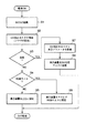
まず、システムの電源が投入されると、BIOSが起動して、各種の初期化処理を実行する(ステップS1)。具体的には、BIOS−ROM16からBIOS(プログラム)が読出されて、メモリ13にセットされることにより、BIOSが起動することになる。
【0023】
BIOSは、グラフィックスコントローラ14を介して、DVI対応モニタ145の接続(DVI対応コネクタの接続)の検出処理を行なう(ステップS2)。BIOSは、DVI対応モニタ145の接続を検出した場合、それを示すフラグ情報をメモリ13にセットする。
【0024】
続いて、BIOSは、メモリ13の値を参照してDVI対応モニタ145が接続されているか否かを判断する(ステップS3)
ここで、BIOSは、メモリ13内のフラグの値を参照し、DVI対応モニタ145が接続されていないと判断した場合には、アナログRGBモニタの接続を判定する(ステップS3のNO,S4)。即ち、CRTモニタ142またはTVモニタ144が接続されているか否かを判定する(ステップS4)。いずれかかが接続されている場合には、BIOSは、システムの表示装置としてCRTモニタ142またはTVモニタ144を機能させるように初期化を行う(ステップS6)。
【0025】
また、アナログRGBモニタが接続されていない場合には(ステップS4のNO)、BIOSは、システムに標準装備されているLCDモニタ143を表示装置として機能させるように初期化を行う(ステップS5)。
【0026】
一方、BIOSは、メモリ13内のフラグを参照し、DVI対応モニタ145が接続されていると判断した場合には(ステップS3のYES)、図1に示すように、DVI対応モニタ145に内蔵されているROM100から表示パラメータ情報を読出して取得する(ステップS7)。表示パラメータ情報は、DVI対応モニタ145を表示制御するための解像度やリフレッシュレートなどの表示パラメータを示す情報であり、メモリ13にセットされる。BIOSは、DVI対応モニタ145を、システムの表示装置として機能させるように取得した表示パラメータ情報に基づき初期化を行う(ステップS8)。
【0027】
以上要するに、システムの電源投入直後に、DVI対応モニタ145が接続されている場合には、BIOSにより自動的にDVI対応モニタ145を表示装置として設定する。従って、ユーザは、特に高解像で映像などを表示させるために、DVI対応モニタ145を使用したい場合に、当該モニタ145をシステムに接続するだけでDVI対応モニタを表示装置として使用できる。具体的には、ユーザは、DVI対応モニタ145をシステムの専用のコネクタに接続し、電源を投入すれば、自動的にDVI対応モニタ145を表示装置として機能させることができる。換言すれば、ユーザは、DVI対応モニタ145を表示装置として使用するための特別の操作を必要としない。
【0028】
図3は、コンピュータシステムにおいて、システムSETUPメニュの表示画面図を示す。
【0029】
図3に示す表示選択画面51は、各表示デバイス名が表示されており、本コンピュータシステムの起動時に優先的に設定したい表示デバイスを設定可能とするものである。
【0030】
例えば、図3で示す例では、DVIモニタの横に表示されている四角が黒く塗りつぶされており、パーソナルコンピュータ起動時に優先的に表示デバイスとして使用するように設定される。DVIモニタ以外にも、パーソナルコンピュータ標準のメインディスプレイであるLCDモニタ、外部のアナログRGBモニタ,、LCDモニタとアナログRGBモニタの同時表示、自動選択といったメニュが表示される。
【0031】
ここで、自動選択とは、パーソナルコンピュータ起動時に、外部接続されている外部モニタを検出し、接続されている外部モニタの中で所定の優先順位で初期化を行うものである。
【0032】
この表示選択画面51で設定された情報は、BIOS−ROM16に記憶される。
【0033】
続いて、図4は上記のシステムSETUPメニュに従って本実施形態の表示装置設定処理を実行するときの手順を示すフローチャートである。
【0034】
まず、システムの電源が投入されると、BIOSが起動して、各種の初期化処理を実行する(ステップS11)。この際に、メモリ13へBIOS−ROM16の一部がコピーされてCPUによる初期化が行われるが、前述の表示画面の設定データもコピーされる。
【0035】
次に、表示装置設定処理に移行すると、BIOSは、グラフィックスコントローラ14を介して、DVI対応モニタ145の接続(DVI対応コネクタの接続)を検出処理を行なう(ステップS12)。BIOSは、DVI対応モニタ145の接続を検出した場合、それを示すフラグ情報をメモリ13にセットする。
【0036】
続いて、BIOSは、表示選択画面51で設定された表示デバイスが何であるかをメモリ13に記憶されている表示画面の設定データを参照する。表示装置としてLCDモニタ143がセットされている場合には(ステップS13のYES)、LCDモニタ143を表示装置として機能させるように初期化を行う(ステップS19)。
【0037】
続いて、表示選択画面51でLCDモニタが設定されていない場合は(ステップS13のNO)、BIOSは、メモリ13に記憶されている表示画面の設定データを参照し、表示装置としてアナログRGBモニタがセットされている場合には(ステップS14のYES)、CRTモニタ142またはTVモニタ144の一方が接続されているか否かを判断する(ステップS20)。ここで、CRTモニタ142またはTVモニタ144の一方が接続されている場合は、実際に接続されているモニタを表示装置として機能させるように初期化を行う(ステップS21)。但し、表示選択画面51でアナログRGBモニタを優先的に表示デバイスとして使用するように設定されている場合でも、CRTモニタ142またはTVモニタ144のいずれもが実際に接続されていない場合には(ステップS20のNO)、BIOSは、標準装備のLCDモニタ143を表示装置として機能させるように初期化を行う(ステップS19)。
【0038】
さらに、表示選択画面51でアナログRGBモニタがセットされていない場合(ステップS14のNO)、BIOSは、メモリ13に記憶されている表示画面の設定データを参照する。表示装置としてDVI対応モニタ145が設定されている場合には(ステップS15のYES)、メモリ13を参照してフラグ情報をチェックする(ステップS16)。BIOSは、フラグ情報がメモリ13にセットされているときには、DVI対応モニタ145が接続されていると判定する(ステップS18のYES)。
【0039】
従って、BIOSは、DVI対応モニタ145に内蔵されているROM100から表示パラメータ情報を読出して取得する(ステップS23)。さらに、BIOSは、DVI対応モニタ145を、システムの表示装置として機能させるように、取得した表示パラメータに基づいて初期化を行う(ステップS24)。
【0040】
一方、フラグ情報がメモリ13にセットされていない場合(ステップS18のNO)、DVI対応モニタ145が実際には接続されていないと判断し、BIOSは、アナログRGBモニタが実際に接続されていか否かを判定する(ステップS20)。即ち、BIOSは、DVI対応モニタ145の代わりに、CRTモニタ142またはTVモニタ144の一方が接続されていれば(ステップS20のYES)、それを表示装置として設定する(ステップS21)。CRTモニタ142またはTVモニタ144のいずれも接続されていない場合には(ステップS20のNO)、BIOSは、標準装備のLCDモニタ143を表示装置として設定する(ステップS19)。
【0041】
また、BIOSは、メモリ13に記憶されている表示画面の設定データを参照し、表示装置としてLCDモニタ143とアナログRGBモニタの両方がセットされている場合には、それらを表示装置として設定する(ステップS16のYES,S22)。但し、アナログRGBモニタとして、CRTモニタ142またはTVモニタ144の一方が実際に接続されている必要がある。どちらも接続されていない場合は、LCDモニタ143のみとなる。
【0042】
なお、表示選択画面51で「自動選択」がセットされている場合には、BIOSは、以下の優先度で表示装置の初期化を行う。DVI対応モニタ145が実際に接続されていれば、当該モニタ145を表示装置として設定する。また、アナログRGBモニタのCRTモニタ142またはTVモニタ144の一方が接続されていれば、それを表示装置として設定する。DVI対応モニタ145及びアナログRGBモニタのいずれも接続されていない場合には、BIOSは、標準装備のLCDモニタ143を表示装置として設定する。
【0043】
以上要するに、DVI対応モニタ145が表示選択画面51でセットされて、かつ実際に接続されている場合には、BIOSは、自動的にDVI対応モニタ145を表示装置として設定する。従って、表示選択画面51ででDVIモニタ145を優先的に使用するようにセットされていれば、ユーザは、DVI対応モニタ145をシステムの所定のコネクタに接続し、電源を投入すれば、自動的にDVI対応モニタ145を表示装置として機能させることができる。
【0044】
(変形例)
図5は、本実施形態の変形例に関するフローチャートである。
【0045】
本変形例は、OS(Operating System)の起動後に、当該OSの制御下で起動するアプリケーションでの表示装置の設定切り替え処理に関する。
【0046】
前述したように、システムの電源投入直後に、BIOSが起動して、表示装置設定処理を含む一連の初期化処理を実行する。ここでは、起動時にLCDモニタ143を優先デバイスとして初期化されて使用可能な状態となった場合を想定している。このBIOSによる初期化処理の終了後に、OSが起動して、各種のアプリケーションの実行が可能となる。
【0047】
ここで、図1に示すように、本変形例は、例えばDVD(Digital Video Disc)プレーヤ300が接続されていることを想定する。システムは、HDD17に格納されている映像再生用アプリケーションを起動し、DVDプレーヤ300にセットされたDVDから映像を再生する処理を開始する(ステップS31,S32のYES)。
【0048】
このとき、OSは、映像再生用アプリケーションを起動したときに、メモリ13のフラグ情報をチェックし、DVI対応モニタ145が接続されているか否かを判定する(ステップS33)。ここで、フラグ情報は、前述したように、システムの電源投入直後に、BIOSによりメモリ13にセットされたものである。
【0049】
OSは、フラグ情報がメモリ13にセットされているときには、DVI対応モニタ145が接続されていると判定する(ステップS33のYES)。OSは、DVI対応モニタ145に内蔵されているROM100から表示パラメータ情報を読出して取得する(ステップS34)。さらに、OSは、現時点でシステムの表示装置として設定されている例えばLCDモニタ143から、DVI対応モニタ145をシステムの表示装置として機能させるように切り替える(ステップS35)。
【0050】
これにより、映像再生用アプリケーションは、DVDプレーヤ300にセットされたDVDから映像を再生し、高解像度のDVI対応モニタ145の画面上に映像を再生表示する(ステップS36)。換言すれば、グラフィックスコントローラ14は、映像再生用アプリケーションにより再生されたデジタル映像信号をDDVI対応モニタ145に出力する。
【0051】
一方、DVI対応モニタ145が接続されていない場合には、OSは、アナログRGBモニタが実際に接続されていか否かを判定する(ステップS33のNO,S37)。即ち、OSは、DVI対応モニタ145の代わりに、CRTモニタ142またはTVモニタ144の一方が接続されていれば、それを表示装置として設定する(ステップS37のYES,S38)。
【0052】
従って、映像再生用アプリケーションは、DVDプレーヤ300にセットされたDVDから映像を再生し、CRTモニタ142またはTVモニタ144の画面上に映像を再生表示する(ステップS36)。
【0053】
なお、DVI対応モニタ145及びアナログRGBモニタのいずれも接続されていない場合には、OSは、標準装備のLCDモニタ143を表示装置としてそのまま維持する(ステップS39)。従って、映像再生用アプリケーションは、DVDプレーヤ300にセットされたDVDから映像を再生し、LCDモニタ143の画面上に映像を再生表示することになる(ステップS36)。
【0054】
以上要するに本変形例によれば、OSは、映像再生用アプリケーションが起動したときには、表示装置として初期設定されたモニタ(例えばLCDモニタ143)からDVI対応モニタ145に設定を切り替える。従って、例えばDVDから映像を再生する場合に、高解像度のDVI対応モニタ145をシステムに接続すれば、自動的にDVI対応モニタ145を表示装置として切り替えて、再生表示することができる。従って、ユーザは、DVI対応モニタ145をシステムに接続するだけで、表示装置の切り替えのための特別の操作を要することなく、高解像度の画面上に映像を再生することができる。
【0055】
なお、本実施形態及び変形例は、LCDモニタ143を標準装備のモニタ(通常使用モニタ)として使用するノート型パーソナルコンピュータを想定している。これに限らず、複数種のモニタを表示装置として使用可能な電子機器であれば、本実施形態及び変形例の表示装置設定方法を適用できる。例えば、携帯型のTVチューナ付きDVDプレーヤのような電子機器において、標準装備のモニタとしてはLCDモニタを想定する。このDVDプレーヤに、オプションとして据え置き型のDVI対応モニタを接続したときに、当該DVDプレーヤは、自動的に表示装置としてDVI対応モニタを設定する。これにより、ユーザは、外出先では本体に内蔵されているLCDモニタを使用し、DVI対応モニタを使用できる場所では当該モニタを接続するだけで使用できる。
【0056】
【発明の効果】
以上詳述したように本発明によれば、ディジタルディスプレイ規格のモニタが接続された場合には、当該モニタを自動的に表示装置として設定できる電子機器を提供できる。
【図面の簡単な説明】
【図1】本発明の実施形態に関するコンピュータシステムの構成を示すブロック図。
【図2】本実施形態に関するコンピュータシステムのBIOSの処理手順を説明するためのフローチャート。
【図3】本実施形態に関するシステムSETUPメニュ画面の一例を示す図。
【図4】本実施形態において、システムセットアップが関与した場合のBIOSの処理手順を説明するためのフローチャート。
【図5】本実施形態の変形例を説明するためのフローチャート。
【図6】本実施形態に関するコンピュータシステムの外観を示す図。
【符号の説明】
10…本体、11…マイクロプロセッサ(CPU)、12…グラフィック・メモリコントローラハブ、13…メモリ(システムメモリ)、
14…グラフィックスコントローラ、15…I/Oハブ、
16…BIOS−ROM、17…ハードディスクドライブ(HDD)、
18…サウンドコントローラ、19…エンベッデッドコントローラ(EC)、
20…キーボード、100…DVI対応モニタの内蔵ROM、
141…ビデオメモリ(VRAM)、142…CRTモニタ、
143…LCDモニタ、144…TVモニタ、145…DVI対応モニタ、
200…TVチューナ、300…DVDプレーヤ。[0001]
TECHNICAL FIELD OF THE INVENTION
The present invention generally relates to the field of electronic devices that can use a plurality of types of display monitors, and more particularly to a method of setting a display monitor to function as a display device.
[0002]
[Prior art]
Generally, electronic devices such as notebook personal computers and portable digital players are equipped with a liquid crystal display (LCD) monitor as a standard display device.
[0003]
2. Description of the Related Art In recent years, monitors (hereinafter, referred to as DVI-compatible monitors or DVI monitors) based on a digital display standard called DVI (Digital Visual Interface) have become widespread. The DVI-compatible monitor is a display that directly generates an image from a digital signal, and is capable of displaying, in particular, a high-quality image or the like.
[0004]
By the way, in a notebook personal computer, an analog RGB monitor (usually a CRT monitor) or an LCD monitor is selected as a display device regardless of whether or not a DVI-compatible monitor is connected. For example, when a user uses a DVI-compatible monitor to display a video reproduced from a DVD drive, a TV tuner, or the like, the user needs to execute special utility software. In other words, the user is required to consciously switch from a standard equipment such as an LCD monitor to a DVI-compatible monitor as a display device.
[0005]
Here, some computers have a function of detecting the connection of the DVI-compatible monitor when the DVI-compatible monitor is connected to the dedicated connector (for example, see Patent Document 1).
[0006]
[Patent Document 1]
JP-A-2002-169532 (abstract, FIG. 1)
[0007]
[Problems to be solved by the invention]
As described above, in the notebook personal computer, the connection of the DVI-compatible monitor is automatically detected. However, a user is required to perform an operation for executing special utility software in order for the DVI-compatible monitor connected to the computer to function as a display device.
[0008]
Therefore, an object of the present invention is to provide an electronic apparatus that can automatically set a monitor of a digital display standard as a display device, particularly when the monitor is connected.
[0009]
[Means for Solving the Problems]
An aspect of the present invention is to provide an electronic apparatus that can use a plurality of types of display monitors including a display monitor that is provided as a standard (usually used) in a main body, when a display monitor of a digital display standard such as the DVI standard is connected to the main body. The present invention also relates to an electronic device that causes the display monitor to function as a display device.
[0010]
An electronic device according to an aspect of the present invention is a portable electronic device in which a first display device is incorporated in a main body, wherein a connection terminal provided on the main body and capable of outputting a digital video signal; A second display device capable of performing a display operation by receiving a video signal as input, a determination unit that determines whether or not the second display device is connected to the connection terminal; and that the second display device is connected by the determination unit. When it is determined, the setting means performs a predetermined setting process so that the second display device can perform a display operation using the digital video signal.
[0011]
Specifically, the setting unit acquires display parameter information from, for example, a second display device (display monitor) of the DVI standard, and performs setting processing to function as a display device using the display parameter information. Thus, the user can automatically activate the display monitor by simply connecting the DVI standard display monitor capable of reproducing and displaying a video or the like with high image quality to the electronic device.
[0012]
BEST MODE FOR CARRYING OUT THE INVENTION
Embodiments of the present invention will be described below with reference to the drawings.
[0013]
(System configuration)
FIG. 1 is a block diagram showing a system configuration of, for example, a notebook personal computer as an electronic apparatus according to the present embodiment. FIG. 6 is a diagram illustrating an appearance of the computer.
[0014]
As shown in FIG. 1, the computer system includes a microprocessor (CPU) 11, a graphic
[0015]
The
[0016]
The
[0017]
The I /
[0018]
Further, a PCI (Peripheral Component Interconnect)
[0019]
Here, in the computer, as shown in FIG. 6, a
[0020]
Further, in the present embodiment, the
[0021]
(Procedure for display device setting process)
Hereinafter, the procedure of the display device setting process in the computer system of the present embodiment will be described with reference to the flowchart of FIG. 2 together with FIG.
[0022]
First, when the power of the system is turned on, the BIOS starts up and executes various initialization processes (step S1). More specifically, the BIOS (program) is read from the BIOS-
[0023]
The BIOS detects the connection of the DVI monitor 145 (connection of the DVI connector) via the graphics controller 14 (step S2). When detecting the connection of the DVI-
[0024]
Subsequently, the BIOS refers to the value in the
Here, when the BIOS refers to the value of the flag in the
[0025]
If the analog RGB monitor is not connected (NO in step S4), the BIOS performs initialization so that the
[0026]
On the other hand, when the BIOS refers to the flag in the
[0027]
In short, if the DVI-
[0028]
FIG. 3 shows a display screen of the system SETUP menu in the computer system.
[0029]
The
[0030]
For example, in the example shown in FIG. 3, the square displayed on the side of the DVI monitor is blacked out, and is set to be preferentially used as a display device when the personal computer is started. In addition to the DVI monitor, menus such as an LCD monitor as a main display of a personal computer, an external analog RGB monitor, simultaneous display of the LCD monitor and the analog RGB monitor, and automatic selection are displayed.
[0031]
Here, the automatic selection means detecting an externally connected external monitor at the time of starting the personal computer, and performing initialization with a predetermined priority among the connected external monitors.
[0032]
The information set on the
[0033]
Subsequently, FIG. 4 is a flowchart showing a procedure when executing the display device setting processing of the present embodiment according to the above-mentioned system SETUP menu.
[0034]
First, when the power of the system is turned on, the BIOS starts up and executes various initialization processes (step S11). At this time, a part of the BIOS-
[0035]
Next, when the process proceeds to the display device setting process, the BIOS detects a connection of the DVI compatible monitor 145 (connection of the DVI compatible connector) via the graphics controller 14 (step S12). When detecting the connection of the DVI-
[0036]
Subsequently, the BIOS refers to the setting data of the display screen stored in the
[0037]
Subsequently, when the LCD monitor is not set on the display selection screen 51 (NO in step S13), the BIOS refers to the setting data of the display screen stored in the
[0038]
Further, when the analog RGB monitor is not set on the display selection screen 51 (NO in step S14), the BIOS refers to the setting data of the display screen stored in the
[0039]
Therefore, the BIOS reads and acquires the display parameter information from the ROM 100 built in the DVI compatible monitor 145 (step S23). Further, the BIOS initializes the DVI-
[0040]
On the other hand, if the flag information is not set in the memory 13 (NO in step S18), it is determined that the
[0041]
In addition, the BIOS refers to the setting data of the display screen stored in the
[0042]
When "automatic selection" is set on the
[0043]
In short, when the DVI-
[0044]
(Modification)
FIG. 5 is a flowchart relating to a modification of the present embodiment.
[0045]
This modification relates to a process of switching settings of a display device by an application started under the control of an OS (Operating System) after the OS is started.
[0046]
As described above, immediately after the system power is turned on, the BIOS starts up and executes a series of initialization processing including the display device setting processing. Here, it is assumed that the
[0047]
Here, as shown in FIG. 1, this modification assumes that a DVD (Digital Video Disc)
[0048]
At this time, when activating the video reproduction application, the OS checks the flag information in the
[0049]
When the flag information is set in the
[0050]
Accordingly, the video reproduction application reproduces the video from the DVD set in the
[0051]
On the other hand, when the
[0052]
Therefore, the video reproduction application reproduces the video from the DVD set in the
[0053]
If neither the DVI-
[0054]
In short, according to the present modification, when the video playback application is started, the OS switches the setting from the monitor (for example, the LCD monitor 143) initially set as the display device to the DVI-
[0055]
Note that the present embodiment and the modified example assume a notebook personal computer that uses the
[0056]
【The invention's effect】
As described above in detail, according to the present invention, when a monitor conforming to the digital display standard is connected, an electronic device that can automatically set the monitor as a display device can be provided.
[Brief description of the drawings]
FIG. 1 is an exemplary block diagram showing the configuration of a computer system according to an embodiment of the present invention.
FIG. 2 is an exemplary flowchart for explaining the processing procedure of the BIOS of the computer system according to the embodiment;
FIG. 3 is a view showing an example of a system SETUP menu screen according to the embodiment;
FIG. 4 is a flowchart for explaining a BIOS processing procedure when a system setup is involved in the embodiment;
FIG. 5 is a flowchart for explaining a modification of the embodiment.
FIG. 6 is an exemplary view showing the appearance of a computer system according to the embodiment.
[Explanation of symbols]
10: body, 11: microprocessor (CPU), 12: graphic / memory controller hub, 13: memory (system memory),
14 ... Graphics controller, 15 ... I / O hub,
16 BIOS-ROM, 17 hard disk drive (HDD),
18 ... Sound controller, 19 ... Embedded controller (EC),
20 ... keyboard, 100 ... built-in ROM of DVI compatible monitor,
141: video memory (VRAM), 142: CRT monitor,
143 ... LCD monitor, 144 ... TV monitor, 145 ... DVI compatible monitor,
200 ... TV tuner, 300 ... DVD player.
Claims (17)
前記本体に設けられて、デジタル映像信号の出力が可能な接続端子と、
前記デジタル映像信号を入力として表示動作の可能な第2の表示装置が、前記接続端子に接続されているか否かを判定する判定手段と、
前記判定手段により前記第2の表示装置が接続されていると判定された場合に、前記第2の表示装置に対して、前記デジタル映像信号による表示動作が可能となるように所定の設定処理を行なう設定手段とを具備したことを特徴とする電子機器。In a portable electronic device in which a first display device is incorporated in a main body,
A connection terminal provided on the main body and capable of outputting a digital video signal;
A second display device capable of performing a display operation by using the digital video signal as input, a determination unit configured to determine whether or not the second display device is connected to the connection terminal;
When the determination unit determines that the second display device is connected, a predetermined setting process is performed on the second display device so that a display operation using the digital video signal is enabled. An electronic device comprising: setting means for performing the setting.
前記判定手段により、前記第2の表示装置が接続されていると判定された場合に、前記第2の表示装置に予め記憶されている前記第2の表示装置の表示に関する表示パラメータ情報を取得し、当該表示パラメータ情報を使用して前記第2の表示装置の設定処理を行うことを特徴とする請求項1に記載の電子機器。The setting means,
When the determination unit determines that the second display device is connected, the display unit obtains display parameter information related to the display of the second display device, which is stored in the second display device in advance. The electronic apparatus according to claim 1, wherein the setting processing of the second display device is performed using the display parameter information.
前記判定手段により、前記第2の表示装置が接続されていると判定されなかった場合、前記第1の表示装置を表示装置として機能させるように設定処理を行なうことを特徴とする請求項1に記載の電子機器。The setting means,
2. The apparatus according to claim 1, wherein, if the determination unit does not determine that the second display device is connected, a setting process is performed to cause the first display device to function as a display device. Electronic device as described.
前記本体に設けられて、デジタル映像信号の出力が可能な接続端子と、
前記本体の電源オン時に、前記デジタル映像信号を入力として表示動作の可能な第2の表示装置が前記接続端子に接続されているか否かを判定する判定手段と、
前記判定手段により前記第2の表示装置が接続されていると判定された場合に、前記第2の表示装置に対して、前記デジタル映像信号によるデータ表示が可能となるように所定の設定処理を行なう設定手段とを具備したことを特徴とする電子機器。In a portable electronic device in which a first display device is incorporated in a main body,
A connection terminal provided on the main body and capable of outputting a digital video signal;
A determination unit configured to determine whether a second display device capable of performing a display operation by using the digital video signal as an input is connected to the connection terminal when the main body is turned on,
When the determination unit determines that the second display device is connected, a predetermined setting process is performed on the second display device so that data display using the digital video signal is enabled. An electronic device comprising: setting means for performing the setting.
前記判定手段により、前記第2の表示装置が接続されていると判定された場合に、前記第2の表示装置に予め記憶されている表示パラメータ情報を取得し、当該表示パラメータ情報を使用して前記第2の表示装置の設定処理を行うことを特徴とする請求項5に記載の電子機器。The setting means,
When it is determined by the determination unit that the second display device is connected, display parameter information stored in advance in the second display device is acquired, and the display parameter information is used. 6. The electronic device according to claim 5, wherein a setting process of the second display device is performed.
前記本体に設けられて、デジタル映像信号の出力が可能な接続端子と、
前記デジタル映像信号を入力として表示動作の可能な第2の表示装置が、前記接続端子に接続されているか否かを判定する判定手段と、
映像再生用アプリケーションを実行する手段と、
前記映像再生用アプリケーションの実行時に、前記判定手段により前記第2の表示装置が接続されていると判定された場合には前記第2の表示装置を表示装置として機能させるように設定処理を行なう設定手段とを具備したことを特徴とする電子機器。In a portable electronic device in which a first display device is incorporated in a main body,
A connection terminal provided on the main body and capable of outputting a digital video signal;
A second display device capable of performing a display operation by using the digital video signal as input, a determination unit configured to determine whether or not the second display device is connected to the connection terminal;
Means for executing a video playback application;
A setting for performing a setting process to cause the second display device to function as a display device when the determination unit determines that the second display device is connected at the time of executing the video reproduction application; An electronic device comprising:
前記設定手段は、前記映像再生用アプリケーションの実行時に、前記接続情報に基づいて、前記第2の表示装置が接続されているか否かを判断し、前記第2の表示装置が接続されている場合は前記第2の表示装置を表示装置として機能させるように設定する請求項7に記載の電子機器。The determination unit has a unit that determines whether or not the second display device is connected immediately after power-on of the electronic device, and stores the determination result as connection information,
The setting means determines whether or not the second display device is connected based on the connection information when the video playback application is executed, and determines whether the second display device is connected. The electronic apparatus according to claim 7, wherein the setting is performed so that the second display device functions as a display device.
前記第1の表示装置は、液晶ディスプレイ装置またはアナログ方式の表示装置であることを特徴とする請求項1から請求項8のいずれか1項に記載の電子機器。The second display device is a display device according to the DVI (Digital Visual Interface) standard,
9. The electronic apparatus according to claim 1, wherein the first display device is a liquid crystal display device or an analog display device.
前記本体に設けられて、デジタル映像信号の出力が可能な接続端子と、
前記デジタル映像信号を入力として表示動作の可能な第2の表示装置が、前記接続端子に接続されているか否かを判定する判定手段と、
前記本体に設けられて、記録メディアからデータを読み出すメディア駆動装置と、
前記メディア駆動装置により前記記録メディアから読み出した映像データを復調し再生する映像再生用アプリケーションを実行する手段と、
前記映像再生用アプリケーションの実行時に、前記判定手段により前記第2の表示装置が接続されていると判定された場合には、前記第2の表示装置へ前記映像データを出力する出力手段とを具備することを特徴とする電子機器。In a portable electronic device in which a first display device is incorporated in a main body,
A connection terminal provided on the main body and capable of outputting a digital video signal;
A second display device capable of performing a display operation by using the digital video signal as input, a determination unit configured to determine whether or not the second display device is connected to the connection terminal;
A medium driving device provided in the main body, for reading data from a recording medium;
Means for executing a video reproduction application for demodulating and reproducing video data read from the recording medium by the media driving device;
Output means for outputting the video data to the second display device when the determination unit determines that the second display device is connected when the video playback application is executed. Electronic equipment characterized by doing.
前記接続端子に前記デジタル映像信号を入力として表示動作の可能な第2の表示装置が接続されているか否かを判定するステップと、
前記判定手段の判定結果に基づいて、前記第2の表示装置が接続されている場合は、前記第2の表示装置に予め記憶されている表示パラメータ情報を取得するステップと、
前記表示パラメータ情報を使用して前記第2の表示装置を表示装置として設定させるステップとを有することを特徴とする表示装置設定方法。A display device setting method applied to an electronic device having a first display device and a connection terminal capable of outputting a digital video signal to an external device,
Determining whether or not a second display device capable of performing a display operation with the digital video signal being input to the connection terminal is connected;
Acquiring the display parameter information stored in advance in the second display device when the second display device is connected, based on a result of the determination by the determination unit;
Using the display parameter information to set the second display device as a display device.
電子機器の電源投入後に、前記接続端子に前記デジタル映像信号を入力として表示動作の可能な第2の表示装置が接続されているか否かを判定するステップと、
所定の指示に応じて映像再生用アプリケーションを実行するステップと、
前記映像再生用アプリケーションの実行時に、前記判定ステップの判定結果に基づいて、前記第2の表示装置が接続されているときには前記第2の表示装置を表示装置として設定させる表示設定ステップとを有することを特徴とする表示装置設定方法。In a display device setting method of an electronic device having a first display device and a connection terminal capable of outputting a digital video signal to the outside,
After turning on the power of the electronic device, a step of determining whether a second display device capable of performing a display operation with the digital video signal being input to the connection terminal is connected,
Executing a video playback application in response to a predetermined instruction;
A display setting step of setting the second display device as a display device when the second display device is connected, based on a result of the determination at the time of execution of the video reproduction application. A display device setting method characterized by the above-mentioned.
前記映像再生用アプリケーションの実行時に、前記判定ステップの判定結果に基づいて、前記第2の表示装置が接続されていないときには前記第1の表示装置を表示装置として機能させることを特徴とする請求項14に記載の表示装置設定方法。The display setting step includes:
The method according to claim 1, wherein the first display device functions as a display device when the second display device is not connected, based on a result of the determination in the execution of the video reproduction application. 15. The display device setting method according to 14.
前記表示設定ステップは、前記映像再生用アプリケーションの実行時に、前記接続情報に基づいて、前記第2の表示装置が接続されているときには前記第2の表示装置を表示装置として機能させるように制御する請求項14に記載の表示装置設定方法。The determining step stores a determination result of determining whether the second display device is connected as connection information,
The display setting step controls the second display device to function as a display device when the second display device is connected, based on the connection information, when the video playback application is executed. The display device setting method according to claim 14.
Priority Applications (7)
| Application Number | Priority Date | Filing Date | Title |
|---|---|---|---|
| JP2003063686A JP3828498B2 (en) | 2003-03-10 | 2003-03-10 | Electronic device and display device setting method |
| EP04004077.6A EP1457964B1 (en) | 2003-03-10 | 2004-02-23 | Method and apparatus for activating a DVI monitor |
| US10/795,345 US7411568B2 (en) | 2003-03-10 | 2004-03-09 | Method and apparatus for controlling display monitors provided on an electronic apparatus |
| CNB2004100282593A CN100341044C (en) | 2003-03-10 | 2004-03-10 | Method and apparatus for controlling displaying monitor of electronic apparatus |
| US12/169,320 US20080272984A1 (en) | 2003-03-10 | 2008-07-08 | Method and apparatus for controlling display monitors provided on an electronic apparatus |
| US12/948,942 US20110063531A1 (en) | 2003-03-10 | 2010-11-18 | Method and apparatus for controlling display monitors provided on an electronic apparatus |
| US12/948,948 US8957832B2 (en) | 2003-03-10 | 2010-11-18 | Method and apparatus for controlling display monitors provided on an electronic apparatus |
Applications Claiming Priority (1)
| Application Number | Priority Date | Filing Date | Title |
|---|---|---|---|
| JP2003063686A JP3828498B2 (en) | 2003-03-10 | 2003-03-10 | Electronic device and display device setting method |
Publications (2)
| Publication Number | Publication Date |
|---|---|
| JP2004271987A true JP2004271987A (en) | 2004-09-30 |
| JP3828498B2 JP3828498B2 (en) | 2006-10-04 |
Family
ID=32767897
Family Applications (1)
| Application Number | Title | Priority Date | Filing Date |
|---|---|---|---|
| JP2003063686A Expired - Lifetime JP3828498B2 (en) | 2003-03-10 | 2003-03-10 | Electronic device and display device setting method |
Country Status (4)
| Country | Link |
|---|---|
| US (4) | US7411568B2 (en) |
| EP (1) | EP1457964B1 (en) |
| JP (1) | JP3828498B2 (en) |
| CN (1) | CN100341044C (en) |
Cited By (9)
| Publication number | Priority date | Publication date | Assignee | Title |
|---|---|---|---|---|
| JP2006323179A (en) * | 2005-05-19 | 2006-11-30 | Casio Comput Co Ltd | Data processor, data processing method and data processing program |
| JP2006338471A (en) * | 2005-06-03 | 2006-12-14 | Matsushita Electric Ind Co Ltd | Connection device automatic controller and device operation switching procedure |
| JP2007280355A (en) * | 2006-04-03 | 2007-10-25 | Aopen Inc | Computer system, computer device to be used for same system, and signal transfer device |
| JP2008104131A (en) * | 2006-09-21 | 2008-05-01 | Sony Computer Entertainment Inc | Information processing apparatus, video display method and os execution method |
| JP4459288B1 (en) * | 2008-12-01 | 2010-04-28 | 株式会社東芝 | Information processing system, information processing apparatus, and information processing method |
| JP2010122538A (en) * | 2008-11-20 | 2010-06-03 | Lenovo Singapore Pte Ltd | Dual-display computer |
| JP2010256392A (en) * | 2009-04-21 | 2010-11-11 | Lenovo Singapore Pte Ltd | Portable-type computer for connecting external display |
| JP2012242883A (en) * | 2011-05-16 | 2012-12-10 | Yamaha Corp | Electronic information processor and program |
| US9459880B2 (en) | 2013-06-28 | 2016-10-04 | Kabushiki Kaisha Toshiba | Information processing apparatus and output control method |
Families Citing this family (13)
| Publication number | Priority date | Publication date | Assignee | Title |
|---|---|---|---|---|
| US7310099B2 (en) * | 2004-05-03 | 2007-12-18 | Dell Products L.P. | Information handling system including detection of inappropriate video connection |
| US20060044314A1 (en) * | 2004-08-24 | 2006-03-02 | Sunil Pandita | System and method for information handling system display selection |
| US7502947B2 (en) * | 2004-12-03 | 2009-03-10 | Hewlett-Packard Development Company, L.P. | System and method of controlling a graphics controller |
| FR2889878B1 (en) * | 2005-08-19 | 2007-10-19 | Roux Julien Le | COMPUTER HOUSING WITH INTEGRATED SCREEN |
| US20070241990A1 (en) * | 2006-04-14 | 2007-10-18 | Smith Douglas L | Method for automatically switching video sources to a display device |
| JP4301262B2 (en) * | 2006-08-08 | 2009-07-22 | セイコーエプソン株式会社 | Multi-display system and display method |
| JP2009151242A (en) * | 2007-12-21 | 2009-07-09 | Toshiba Corp | Information processing device and display control method |
| JP5448576B2 (en) * | 2008-06-03 | 2014-03-19 | キヤノン株式会社 | Display control apparatus, display control method, and program |
| TWI342499B (en) * | 2008-06-18 | 2011-05-21 | Acer Inc | Computer system and a method for indicating a display output device thereof |
| JP4750173B2 (en) * | 2008-11-13 | 2011-08-17 | レノボ・シンガポール・プライベート・リミテッド | Dual display computer |
| KR20110021180A (en) * | 2009-08-25 | 2011-03-04 | 삼성전자주식회사 | Computer system and control method thereof |
| CN103677969B (en) * | 2012-09-20 | 2017-03-15 | 昆达电脑科技(昆山)有限公司 | The display lighting method of many video card systems |
| CN109979411B (en) * | 2019-04-29 | 2021-03-12 | 上海天马有机发光显示技术有限公司 | Display panel, burning method and electrifying method of display panel |
Family Cites Families (24)
| Publication number | Priority date | Publication date | Assignee | Title |
|---|---|---|---|---|
| JPH03226792A (en) * | 1990-01-31 | 1991-10-07 | Nec Corp | Display system of flat panel type display device |
| JPH04225392A (en) * | 1990-12-27 | 1992-08-14 | Toshiba Corp | Display changeover controller |
| JPH0863135A (en) * | 1994-08-26 | 1996-03-08 | Hitachi Ltd | Information processing device |
| JP2552636B2 (en) * | 1995-08-23 | 1996-11-13 | 三洋電機株式会社 | Electronics |
| US5859623A (en) * | 1996-05-14 | 1999-01-12 | Proxima Corporation | Intelligent display system presentation projection arrangement and method of using same |
| JPH11212529A (en) * | 1998-01-21 | 1999-08-06 | Toshiba Corp | Switching controller for display device and switching control method therefor |
| JP3839949B2 (en) | 1998-03-19 | 2006-11-01 | 株式会社東芝 | Computer system |
| TW475140B (en) * | 1998-04-29 | 2002-02-01 | Samsung Electronics Co Ltd | Analog/digital display adapter and a computer system having the same |
| JP4172096B2 (en) * | 1999-06-14 | 2008-10-29 | 三菱電機株式会社 | Image signal generating device, image display device, and control method for image display device |
| JP3504202B2 (en) * | 1999-12-21 | 2004-03-08 | 株式会社ナナオ | Display device |
| JP3408781B2 (en) * | 2000-06-14 | 2003-05-19 | 株式会社ナナオ | Display device distribution device |
| US6721881B1 (en) * | 2000-09-29 | 2004-04-13 | Dell Products L.P. | System and method for determining if a display device configuration has changed by comparing a current indicator with a previously saved indicator |
| KR100349205B1 (en) | 2000-11-17 | 2002-08-21 | 삼성전자 주식회사 | An apparatus for detecting a DVI connector in a digital video signal display system |
| US7123212B2 (en) | 2000-12-22 | 2006-10-17 | Harman International Industries, Inc. | Information transmission and display method and system for a handheld computing device |
| WO2002060179A1 (en) | 2001-01-26 | 2002-08-01 | Fujitsu Limited | Method and apparatus for copy protection, and copy protection program |
| US6784855B2 (en) * | 2001-02-15 | 2004-08-31 | Microsoft Corporation | Methods and systems for a portable, interactive display device for use with a computer |
| JP3754635B2 (en) | 2001-07-17 | 2006-03-15 | Necディスプレイソリューションズ株式会社 | Display monitor input channel switching control device and display monitor input channel switching control method |
| US7327355B2 (en) * | 2001-12-08 | 2008-02-05 | Samsung Electronics Co., Ltd. | LCD monitor with dual interface and control method thereof |
| US7161557B2 (en) * | 2002-04-08 | 2007-01-09 | Clearcube Technology, Inc. | Selectively updating a display in a multi-display system |
| US7123248B1 (en) * | 2002-07-30 | 2006-10-17 | Matrox Electronic Systems Ltd. | Analog multi-display using digital visual interface |
| US8730230B2 (en) * | 2002-10-19 | 2014-05-20 | Via Technologies, Inc. | Continuous graphics display method for multiple display devices during the processor non-responding period |
| US7136042B2 (en) * | 2002-10-29 | 2006-11-14 | Microsoft Corporation | Display controller permitting connection of multiple displays with a single video cable |
| JP2004171131A (en) * | 2002-11-18 | 2004-06-17 | Toshiba Corp | Information processor and display device switching method |
| US7193583B2 (en) * | 2003-12-31 | 2007-03-20 | Zerphy Byron L | Automatic detection of dynamic message sign display panel configuration |
-
2003
- 2003-03-10 JP JP2003063686A patent/JP3828498B2/en not_active Expired - Lifetime
-
2004
- 2004-02-23 EP EP04004077.6A patent/EP1457964B1/en not_active Expired - Lifetime
- 2004-03-09 US US10/795,345 patent/US7411568B2/en active Active
- 2004-03-10 CN CNB2004100282593A patent/CN100341044C/en not_active Expired - Lifetime
-
2008
- 2008-07-08 US US12/169,320 patent/US20080272984A1/en not_active Abandoned
-
2010
- 2010-11-18 US US12/948,942 patent/US20110063531A1/en not_active Abandoned
- 2010-11-18 US US12/948,948 patent/US8957832B2/en active Active
Cited By (11)
| Publication number | Priority date | Publication date | Assignee | Title |
|---|---|---|---|---|
| JP2006323179A (en) * | 2005-05-19 | 2006-11-30 | Casio Comput Co Ltd | Data processor, data processing method and data processing program |
| JP2006338471A (en) * | 2005-06-03 | 2006-12-14 | Matsushita Electric Ind Co Ltd | Connection device automatic controller and device operation switching procedure |
| JP2007280355A (en) * | 2006-04-03 | 2007-10-25 | Aopen Inc | Computer system, computer device to be used for same system, and signal transfer device |
| JP2008104131A (en) * | 2006-09-21 | 2008-05-01 | Sony Computer Entertainment Inc | Information processing apparatus, video display method and os execution method |
| JP2010122538A (en) * | 2008-11-20 | 2010-06-03 | Lenovo Singapore Pte Ltd | Dual-display computer |
| JP4459288B1 (en) * | 2008-12-01 | 2010-04-28 | 株式会社東芝 | Information processing system, information processing apparatus, and information processing method |
| JP2010130660A (en) * | 2008-12-01 | 2010-06-10 | Toshiba Corp | Information processing system, information processing apparatus and information processing method |
| US7907208B2 (en) | 2008-12-01 | 2011-03-15 | Kabushiki Kaisha Toshiba | Information processing system, information processing apparatus, and information processing method for signal conversion |
| JP2010256392A (en) * | 2009-04-21 | 2010-11-11 | Lenovo Singapore Pte Ltd | Portable-type computer for connecting external display |
| JP2012242883A (en) * | 2011-05-16 | 2012-12-10 | Yamaha Corp | Electronic information processor and program |
| US9459880B2 (en) | 2013-06-28 | 2016-10-04 | Kabushiki Kaisha Toshiba | Information processing apparatus and output control method |
Also Published As
| Publication number | Publication date |
|---|---|
| EP1457964B1 (en) | 2017-02-15 |
| US20040178968A1 (en) | 2004-09-16 |
| US20110063531A1 (en) | 2011-03-17 |
| US7411568B2 (en) | 2008-08-12 |
| JP3828498B2 (en) | 2006-10-04 |
| US20110063193A1 (en) | 2011-03-17 |
| CN1530920A (en) | 2004-09-22 |
| EP1457964A3 (en) | 2007-11-14 |
| US20080272984A1 (en) | 2008-11-06 |
| CN100341044C (en) | 2007-10-03 |
| US8957832B2 (en) | 2015-02-17 |
| EP1457964A2 (en) | 2004-09-15 |
Similar Documents
| Publication | Publication Date | Title |
|---|---|---|
| JP3828498B2 (en) | Electronic device and display device setting method | |
| JP2005316176A (en) | Electronic equipment and display control method | |
| JP4834472B2 (en) | Information processing apparatus, moving image reproduction method, and program | |
| US20090219441A1 (en) | Information processing apparatus | |
| US20050168638A1 (en) | Information processing apparatus | |
| JP2009044253A (en) | Information processor and output interlocking control method | |
| JP2005338183A (en) | Information equipment and display control method of the equipment | |
| US20090154550A1 (en) | Information processing apparatus | |
| JP2007212578A (en) | Information processing apparatus and display control method applied to the information processing apparatus | |
| US20090044221A1 (en) | Information Processing Apparatus and Program Startup Control Method | |
| JP5010666B2 (en) | Information processing device | |
| JP2007065758A (en) | Information processing apparatus and system control method | |
| JP4854055B2 (en) | Image display device | |
| JP2005338184A (en) | Information processor and display control method | |
| KR101046586B1 (en) | Display device and display system using same | |
| JP2005338185A (en) | Information processor and display control method | |
| JP2013186707A (en) | Television receiver | |
| JP2005340953A (en) | Information apparatus and display control method of the same | |
| JP5238852B2 (en) | Information processing apparatus, moving image reproduction method, and program | |
| JP4945654B2 (en) | REPRODUCTION DEVICE AND REPRODUCTION DEVICE CONTROL METHOD | |
| JP4956650B2 (en) | Reproduction control device and reproduction control method | |
| JP2011171857A (en) | Reproducing device and method of controlling the same | |
| JP2008276569A (en) | Information processor | |
| JP2002051289A (en) | Image reproducing device | |
| JP2010252018A (en) | Television device with disk device |
Legal Events
| Date | Code | Title | Description |
|---|---|---|---|
| A977 | Report on retrieval |
Free format text: JAPANESE INTERMEDIATE CODE: A971007 Effective date: 20051031 |
|
| A131 | Notification of reasons for refusal |
Free format text: JAPANESE INTERMEDIATE CODE: A131 Effective date: 20051115 |
|
| A521 | Request for written amendment filed |
Free format text: JAPANESE INTERMEDIATE CODE: A523 Effective date: 20060116 |
|
| A131 | Notification of reasons for refusal |
Free format text: JAPANESE INTERMEDIATE CODE: A131 Effective date: 20060404 |
|
| A521 | Request for written amendment filed |
Free format text: JAPANESE INTERMEDIATE CODE: A523 Effective date: 20060501 |
|
| TRDD | Decision of grant or rejection written | ||
| A01 | Written decision to grant a patent or to grant a registration (utility model) |
Free format text: JAPANESE INTERMEDIATE CODE: A01 Effective date: 20060704 |
|
| A61 | First payment of annual fees (during grant procedure) |
Free format text: JAPANESE INTERMEDIATE CODE: A61 Effective date: 20060706 |
|
| R151 | Written notification of patent or utility model registration |
Ref document number: 3828498 Country of ref document: JP Free format text: JAPANESE INTERMEDIATE CODE: R151 |
|
| FPAY | Renewal fee payment (event date is renewal date of database) |
Free format text: PAYMENT UNTIL: 20090714 Year of fee payment: 3 |
|
| FPAY | Renewal fee payment (event date is renewal date of database) |
Free format text: PAYMENT UNTIL: 20100714 Year of fee payment: 4 |
|
| FPAY | Renewal fee payment (event date is renewal date of database) |
Free format text: PAYMENT UNTIL: 20110714 Year of fee payment: 5 |
|
| FPAY | Renewal fee payment (event date is renewal date of database) |
Free format text: PAYMENT UNTIL: 20120714 Year of fee payment: 6 |
|
| FPAY | Renewal fee payment (event date is renewal date of database) |
Free format text: PAYMENT UNTIL: 20130714 Year of fee payment: 7 |
|
| S111 | Request for change of ownership or part of ownership |
Free format text: JAPANESE INTERMEDIATE CODE: R313121 Free format text: JAPANESE INTERMEDIATE CODE: R313117 |
|
| R350 | Written notification of registration of transfer |
Free format text: JAPANESE INTERMEDIATE CODE: R350 |
|
| EXPY | Cancellation because of completion of term |