JP2004249282A - Mixing tube and its manufacturing method - Google Patents
Mixing tube and its manufacturing method Download PDFInfo
- Publication number
- JP2004249282A JP2004249282A JP2003383664A JP2003383664A JP2004249282A JP 2004249282 A JP2004249282 A JP 2004249282A JP 2003383664 A JP2003383664 A JP 2003383664A JP 2003383664 A JP2003383664 A JP 2003383664A JP 2004249282 A JP2004249282 A JP 2004249282A
- Authority
- JP
- Japan
- Prior art keywords
- outer frame
- frame member
- partition
- mixing
- passage
- Prior art date
- Legal status (The legal status is an assumption and is not a legal conclusion. Google has not performed a legal analysis and makes no representation as to the accuracy of the status listed.)
- Pending
Links
Images


Classifications
-
- B—PERFORMING OPERATIONS; TRANSPORTING
- B01—PHYSICAL OR CHEMICAL PROCESSES OR APPARATUS IN GENERAL
- B01F—MIXING, e.g. DISSOLVING, EMULSIFYING OR DISPERSING
- B01F25/00—Flow mixers; Mixers for falling materials, e.g. solid particles
- B01F25/40—Static mixers
- B01F25/42—Static mixers in which the mixing is affected by moving the components jointly in changing directions, e.g. in tubes provided with baffles or obstructions
- B01F25/43—Mixing tubes, e.g. wherein the material is moved in a radial or partly reversed direction
- B01F25/432—Mixing tubes, e.g. wherein the material is moved in a radial or partly reversed direction with means for dividing the material flow into separate sub-flows and for repositioning and recombining these sub-flows; Cross-mixing, e.g. conducting the outer layer of the material nearer to the axis of the tube or vice-versa
- B01F25/4321—Mixing tubes, e.g. wherein the material is moved in a radial or partly reversed direction with means for dividing the material flow into separate sub-flows and for repositioning and recombining these sub-flows; Cross-mixing, e.g. conducting the outer layer of the material nearer to the axis of the tube or vice-versa the subflows consisting of at least two flat layers which are recombined, e.g. using means having restriction or expansion zones
-
- B—PERFORMING OPERATIONS; TRANSPORTING
- B01—PHYSICAL OR CHEMICAL PROCESSES OR APPARATUS IN GENERAL
- B01F—MIXING, e.g. DISSOLVING, EMULSIFYING OR DISPERSING
- B01F33/00—Other mixers; Mixing plants; Combinations of mixers
- B01F33/50—Movable or transportable mixing devices or plants
- B01F33/501—Movable mixing devices, i.e. readily shifted or displaced from one place to another, e.g. portable during use
- B01F33/5011—Movable mixing devices, i.e. readily shifted or displaced from one place to another, e.g. portable during use portable during use, e.g. hand-held
-
- B—PERFORMING OPERATIONS; TRANSPORTING
- B01—PHYSICAL OR CHEMICAL PROCESSES OR APPARATUS IN GENERAL
- B01F—MIXING, e.g. DISSOLVING, EMULSIFYING OR DISPERSING
- B01F35/00—Accessories for mixers; Auxiliary operations or auxiliary devices; Parts or details of general application
- B01F35/56—General build-up of the mixers
- B01F35/562—General build-up of the mixers the mixer or mixing elements being collapsible, i.e. when discharging the products
- B01F35/5621—General build-up of the mixers the mixer or mixing elements being collapsible, i.e. when discharging the products the complete mixer being collapsible, i.e. the housing can be collapsed
-
- B—PERFORMING OPERATIONS; TRANSPORTING
- B01—PHYSICAL OR CHEMICAL PROCESSES OR APPARATUS IN GENERAL
- B01F—MIXING, e.g. DISSOLVING, EMULSIFYING OR DISPERSING
- B01F2101/00—Mixing characterised by the nature of the mixed materials or by the application field
- B01F2101/2305—Mixers of the two-component package type, i.e. where at least two components are separately stored, and are mixed in the moment of application
-
- B—PERFORMING OPERATIONS; TRANSPORTING
- B01—PHYSICAL OR CHEMICAL PROCESSES OR APPARATUS IN GENERAL
- B01F—MIXING, e.g. DISSOLVING, EMULSIFYING OR DISPERSING
- B01F2101/00—Mixing characterised by the nature of the mixed materials or by the application field
- B01F2101/36—Mixing of ingredients for adhesives or glues; Mixing adhesives and gas
Abstract
Description
本発明は、ミキシングチューブ及びその製造方法であって、特に2液性エポキシ系接着剤など2種類の流動体の混合に使用するミキシングチューブに好適に利用できる技術に関する。 The present invention relates to a mixing tube and a method for producing the same, and more particularly to a technique which can be suitably used for a mixing tube used for mixing two kinds of fluids such as a two-part epoxy adhesive.
2液型エポキシ系接着剤は主剤と硬化剤とが別々に容易されており、使用時に両者を混合し使用する。従来、この主剤と硬化剤を混合する際には、ナイフ、へら等を用いて手動で混合する方法、スタティックミキサーを用いたディスペンサー又は専用に設計されたミキサーを使用する方法により混合が行われていた。 In the two-pack type epoxy adhesive, the main agent and the curing agent are easily prepared separately, and both are mixed and used at the time of use. Conventionally, when mixing the main agent and the curing agent, mixing is performed by a method of manually mixing using a knife, a spatula, or the like, a method of using a dispenser using a static mixer, or a method of using a specially designed mixer. Was.
しかしながら、従来の方法で材料の混合を行うと以下のような問題があった。2液型エポキシ系接着剤における主剤と硬化剤の硬化は、硬化剤を混合した時から始まり室温でも硬化する。従って、一度使用すると、ナイフ、へら、スタティックミキサー内部、専用ミキサ内の容器に材料が付着し、混合した全ての材料を本来の接着剤の用途に使用できず、固化して捨ててしまうことがあった。 However, mixing materials by a conventional method has the following problems. The curing of the main agent and the curing agent in the two-part epoxy adhesive starts when the curing agent is mixed and cures even at room temperature. Therefore, once used, the material adheres to the knives, spatula, the inside of the static mixer, and the container in the special mixer, and all the mixed materials cannot be used for the purpose of the original adhesive, and are solidified and discarded. there were.
また、作業者によって混合の度合は、作業者の判断によるため、混合された被混合材料の品質に差が生じるという問題点もあった。 In addition, since the degree of mixing depends on the operator's judgment, there is a problem that the quality of the mixed materials to be mixed may be different.
このような問題を鑑みて、本出願人は、既に、流動性のある複数種類の被混合材料を別々に収容する複数の容器を装着し、前記複数の容器から排出された前記複数種類の被混合材料を混合するためのミキシングチューブを発明した。このミキシングチューブは、被混合材料を収容した容器に装着するための入口と、この入口から注入された複数種類の被混合材料を混合するための混合用通路と、この混合用通路によって混合された前記被混合材料を吐出する出口とを有しており、前記混合用通路を前記入口側から前記吐出口側にかけて連続的に押し潰すことにより、前記入口から注入された前記複数種類の被混合材料が、前記混合用通路を通過して混合され、前記入口から注入された被混合材料が、前記被混合通路を通過して混合され、前記出口から吐出されることを特徴としている(特許文献1参照)。 In view of such a problem, the present applicant has already mounted a plurality of containers separately accommodating a plurality of types of materials to be mixed having fluidity, and provided the plurality of types of materials discharged from the plurality of containers. A mixing tube for mixing the mixed materials has been invented. The mixing tube was mixed by the inlet for mounting to the container containing the materials to be mixed, the mixing passage for mixing a plurality of types of the materials to be injected from the inlet, and the mixing passage. An outlet for discharging the material to be mixed, and by continuously crushing the mixing passage from the inlet side to the discharge port side, the plurality of types of the material to be mixed injected from the inlet. Are mixed through the mixing passage, and the material to be mixed injected from the inlet is mixed through the mixing passage and discharged from the outlet (Patent Document 1). reference).
このミキシングチューブの混合用通路は、例えば、被混合材料と同数の変形通路を有する複数の通路ブロックを直列に接続し、通路ブロックの接続部分における各変形通路の出口と入口の向きを適宜に組み合わせることによって、前段の通路ブロックから排出された被混合材料を後段の通路ブロックの入口で分割し、その出口で集合される作用を繰り返すようにした構成である。このミキシングチューブは、通路ブロックの接続数をNとした場合、被混合材料は2のN乗に分割され、十分に混合できるものであった。
しかし、従来のミキシングチューブの被混合材料を2のN乗の理論で混合する形状は複雑であり、その形状を再現することは難しく製造は困難であった。そのため、ミキシングチューブを大量生産することは不可能であり、高価なものとなっていた。 However, the shape of the conventional mixing tube in which the materials to be mixed are mixed according to the 2N power theory is complicated, and it is difficult to reproduce the shape, and it is difficult to manufacture the mixing tube. Therefore, it was impossible to mass-produce the mixing tube, and it was expensive.
本発明は、このような問題を鑑みて成されたものであり、比較的簡易な構成で被混合材料を分割、集合させ十分に被混合材料を混合することができるミキシングチューブ及びそ
の製造方法を提供することを技術的課題とする。
The present invention has been made in view of such a problem, and a mixing tube capable of dividing and assembling materials to be mixed with a relatively simple configuration and sufficiently mixing the materials to be mixed, and a method of manufacturing the same. Making it a technical issue.
本発明に係るミキシングチューブは、前述の技術的課題を解決するために以下のように構成されている。複数種類の被混合材料を通過させ、通過過程において被混合材料に分割及び集合を繰り返し作用させて、被混合材料を混合する第1及び第2混合用通路を有するミキシングチューブであって、前記第1及び第2混合用通路は、前記ミキシングチューブをその被混合材料の通過方向で縦に分割した第1及び第2外枠部材によりその間に仕切り部材を介して形成されており、前記仕切り部には、前記被混合材料の混合方向の一定間隔毎に穴部が設けられおり、第1混合用通路と第2混合用通路とが分割及び集合を繰り返すことにより、通過する被混合材料に分割及び集合を繰り返し作用させることを特徴とする。 The mixing tube according to the present invention is configured as follows in order to solve the above-described technical problem. A mixing tube having first and second mixing passages through which a plurality of types of materials to be mixed are passed and division and assembly are repeatedly performed on the materials to be mixed in a passing process to mix the materials to be mixed. The first and second mixing passages are formed by first and second outer frame members that vertically divide the mixing tube in the direction of passage of the material to be mixed, with a partition member interposed therebetween, and the partition portion has Are provided with holes at regular intervals in the mixing direction of the material to be mixed, and the first mixing passage and the second mixing passage are repeatedly divided and gathered, so that the first mixing passage and the second mixing passage are divided into passing mixed materials. It is characterized in that a set is repeatedly operated.
前記構成により、第1及び第2混合用通路を通過する被混合材料は、前記仕切り部の穴部を通じて分割、集合を繰り返し、十分に混合される。このミキシングチューブは、第1外枠部材、第2外枠部材、及び、仕切り部材の3部材から構成されており、その構成及び組み立ては簡易である。また、前記第1及び第2外枠部材の断面形状は、矩形、円形、菱形等、その形状は限定されない。すなわち、前記穴部を有する仕切り部材を介して形成される複数の混合用通路が合流、分割を繰り返すミキシングチューブであれば良い。 With the above configuration, the materials to be mixed passing through the first and second mixing passages are repeatedly divided and gathered through the holes of the partition, and are sufficiently mixed. This mixing tube is composed of three members, a first outer frame member, a second outer frame member, and a partition member, and the configuration and assembly are simple. The cross-sectional shape of the first and second outer frame members is not limited, such as a rectangle, a circle, and a rhombus. That is, a mixing tube in which a plurality of mixing passages formed via the partition member having the holes are repeatedly joined and divided may be used.
また、本発明に係るミキシングチューブの前記第1混合用通路と第2混合用通路は、断面形状が連続的に変化する複数のエレメントを直列に接続しており、前記仕切り部材の穴部は、前記被混合材料の混合方向において各エレメントの半分の長さに設けられている。 Further, the first mixing passage and the second mixing passage of the mixing tube according to the present invention are connected in series with a plurality of elements having a continuously changing cross-sectional shape, and the hole of the partition member is It is provided at half the length of each element in the mixing direction of the material to be mixed.
前記構成により、被混合材料は断面形状が連続的に変化する各エレメントを通過することで、連続的に圧縮力及び剪断力が加えられる。また、仕切り部材には各エレメントの半分の長さの穴部が設けられているため、各変形通路を通過する被混合材料は規則的に分割、合流を繰り返す。すなわち、それぞれの混合用通路で連続的に圧縮力及び剪断力をうけると共に、他の混合用通路を通過する被混合材料と規則的に合流及び分割することで、混合用通路を通過する複数の被混合材料は均一に混合される。 According to the configuration, the material to be mixed passes through each element having a continuously changing cross-sectional shape, so that a compressive force and a shear force are continuously applied. Further, since the partition member is provided with a hole having a half length of each element, the material to be mixed passing through each deformation passage repeats regularly dividing and merging. That is, while being continuously subjected to a compressive force and a shearing force in each mixing passage, a plurality of materials passing through the mixing passage are formed by regularly joining and dividing with the materials to be mixed passing through the other mixing passages. The materials to be mixed are uniformly mixed.
また、本発明に係るミキシングチューブの前記第1外枠部材、第2外枠部材、及び、仕切り部材の各々が接合する接合部には、前記第1及び第2混合用通路に沿ってその外側につば部が各々設けられており、前記仕切り部材のつば部が前記第1外枠部材と第2外枠部材のつば部に狭持されていることにより、前記第1外枠部材、第2外枠部材、及び、仕切り部材は一体化され、前記第1及び第2混合用通路を形成していることが望ましい。 In addition, the first outer frame member, the second outer frame member, and the joining portion of each of the partition members of the mixing tube according to the present invention are provided on the outside along the first and second mixing passages. The first outer frame member, the second outer frame member, and the second outer frame member are held by the first outer frame member and the second outer frame member. It is desirable that the outer frame member and the partition member be integrated to form the first and second mixing passages.
前記構成により、第1外枠部材、第2外枠部材、及び仕切り部材の3部材を容易に一体化させることができる。すなわち、比較的簡易な構成で容易に被混合材料を十分に混合することができる第1及び第2混合用通路を形成することが可能となる。 According to the above configuration, the three members of the first outer frame member, the second outer frame member, and the partition member can be easily integrated. That is, it is possible to form the first and second mixing passages that can easily and sufficiently mix the materials to be mixed with a relatively simple configuration.
さらに、本発明に係るミキシングチューブの前記第1外枠部材と第2外枠部材には、第1混合用通路と第2混合用通路をそれぞれ分割する中仕切り部が形成されており、前記仕切り部材の穴部において、第1外枠部材の中仕切り部と第2外枠部材の中仕切り部が溶着していることが望ましい。 Further, the first outer frame member and the second outer frame member of the mixing tube according to the present invention are formed with an intermediate partition portion for dividing the first mixing passage and the second mixing passage, respectively. In the hole of the member, it is desirable that the middle partition portion of the first outer frame member and the middle partition portion of the second outer frame member are welded.
前記中仕切り部を設けることにより、第1混合用通路と第2混合用通路をそれぞれ分割することができ、前エレメントから排出された被混練材料を続くエレメントの入口で分割し、その出口で集合するという作用を繰り返すことができる。このミキシングチューブによれば、エレメントの接続数をNとした場合、被混合材料は2のN乗に分割され、十分に
混合することが可能となる。また、この中仕切り部は、前記第1外枠部材の中仕切り部と第2外枠部材の中仕切り部とを溶着することにより形成されており、第1混合用通路及び第2混合用通路を形成すると同時に中仕切り部を形成することが可能となる。このような中仕切り部の構造としては、第1外枠部材及び第2外枠部材の長手方向の断面を略M字に形成する構成を例示できる。さらに、この中仕切り部は、第1外枠部材と第2外枠部材の間に狭持されている仕切り部材に垂直に形成し、仕切り部材の中心に中仕切り部を配置することが望ましい。このように中仕切り部を形成することにより、第1及び第2混合用通路を確実に2分割することが可能となる。
By providing the intermediate partition portion, the first mixing passage and the second mixing passage can be respectively divided, and the material to be kneaded discharged from the previous element is divided at the entrance of the succeeding element and assembled at the exit. Can be repeated. According to this mixing tube, when the number of connected elements is N, the material to be mixed is divided into 2 to the Nth power and can be sufficiently mixed. The middle partition portion is formed by welding the middle partition portion of the first outer frame member and the middle partition portion of the second outer frame member, and forms a first mixing passage and a second mixing passage. Is formed, and at the same time, a partition part can be formed. As a structure of such a middle partition part, the structure which forms the cross section of the longitudinal direction of a 1st outer frame member and a 2nd outer frame member in substantially M shape can be illustrated. Further, it is desirable that the intermediate partition is formed vertically to the partition member sandwiched between the first outer frame member and the second outer frame member, and the intermediate partition is disposed at the center of the partition member. By forming the intermediate partition in this way, it is possible to reliably divide the first and second mixing passages into two.
また、本発明に係るミキシングチューブは、前記第1外枠部材と第2外枠部材には、第1混合用通路と第2混合用通路をそれぞれ分割する中仕切り部が形成されており、この第1外枠部材の中仕切り部と第2外枠部材の中仕切り部が、それぞれ前記仕切り部材と溶着することを特徴としても良い。 Further, in the mixing tube according to the present invention, the first outer frame member and the second outer frame member are formed with a middle partition part for dividing the first mixing passage and the second mixing passage, respectively. The middle partition part of the first outer frame member and the middle partition part of the second outer frame member may be welded to the partition member, respectively.
前記第1外枠部材の中仕切り部と第2外枠部材の中仕切り部をそれぞれ仕切り部材と溶着することによっても、第1混合用通路と第2混合用通路をそれぞれ分割する状態で中仕切り部を形成することができる。従って、前エレメントから排出された被混練材料を続くエレメントの入口で分割し、その出口で集合するという作用を繰り返すことができ、エレメントの接続数をNとした場合、被混合材料を2のN乗に分割し、十分に混合することが可能となる。 The first partition and the second mixing channel are also divided by welding the first partition and the second partition to each other by welding the middle partition and the second partition to the partition. A part can be formed. Therefore, the operation of dividing the material to be kneaded discharged from the previous element at the entrance of the subsequent element and assembling at the exit can be repeated, and when the number of connected elements is N, the material to be mixed is 2 N It is possible to divide into powers and mix well.
さらに、本発明に係るミキシングチューブの仕切り部材の穴部には、前記第1外枠部材と第2外枠部材の中仕切り部と当接する係合部が形成されており、この係合部は、前記第1外枠部材と第2外枠部材の中仕切り部と溶着していることを特徴とすることが望ましい。 Further, in the hole of the partition member of the mixing tube according to the present invention, there is formed an engaging portion which comes into contact with the intermediate partition portion of the first outer frame member and the second outer frame member. It is desirable that the first outer frame member and the second outer frame member are welded to a partition part.
前記係合部を設けることにより、第1外枠部材及び第2外枠部材のの中仕切り部を確実に仕切り部材に固定し、第1混合用通路と第2混合用通路をそれぞれ分割する状態で中仕切り部を形成することが可能となる。また、第1外枠部材の中仕切り部と第2外枠部材の仕切り部材をそれぞれ係合部に固定することができるため、種々の製造方法が可能となる。 By providing the engaging portion, the middle partition portion of the first outer frame member and the second outer frame member is securely fixed to the partition member, and the first mixing passage and the second mixing passage are divided. It becomes possible to form a middle partition part. Further, since the middle partition portion of the first outer frame member and the partition member of the second outer frame member can be respectively fixed to the engagement portions, various manufacturing methods can be performed.
本発明に係るミキシングチューブの製造方法は、熱可塑性樹脂製の前記第1及び第2外枠部材を各々成型するとともに、熱可塑性樹脂製の前記仕切り部材に穴部を形成した後に、前記仕切り部材のつば部を前記第1及び第2外枠部材のつば部で挟みつつ、このつば部の端部を溶着し、前記第1外枠部材、第2外枠部材、及び、前記仕切り部材を一体化させ、第1及び第2混合用通路を形成することを特徴とする。 The method for manufacturing a mixing tube according to the present invention is characterized in that the first and second outer frame members made of a thermoplastic resin are each molded, and the partition member is made after forming a hole in the partition member made of a thermoplastic resin. While sandwiching the brim portion between the brim portions of the first and second outer frame members, the ends of the brim portion are welded, and the first outer frame member, the second outer frame member, and the partition member are integrated. And forming the first and second mixing passages.
前記構成によれば、前記つば部を溶着することで前記混合用通路を形成することが可能であり、ミキシングチューブを容易に製造することが可能である。また、熱可塑性樹脂とは、加熱すると軟化して溶け、冷却すると硬化する性質を有する物質であり、例えば、スチレン系,アクリル系,セルロース系,ポリエチレン系,ビニル系,ナイロン系,フッ化炭素系の樹脂などが挙げられる。 According to the above configuration, the mixing passage can be formed by welding the collar portion, and the mixing tube can be easily manufactured. The thermoplastic resin is a substance having a property of softening and melting when heated and hardening when cooled. Examples thereof include styrene, acrylic, cellulose, polyethylene, vinyl, nylon, and fluorocarbon. And the like.
ここで熱可塑性樹脂の溶着方法を例示して説明する。熱可塑性樹脂の溶着方法としては、大別すると、数10MHzの高周波エネルギーの電解作用によって原子や電子レベルの電位的な運動により被加熱物自体を発熱させ溶着する高周波溶着、周波数20kHz以上の超音波エネルギーをホーンと呼ばれる共鳴体かた超音波振動を被加熱物に伝え強力な摩擦熱を発生させ溶着する超音波溶着、非加熱物の外部にある熱源から熱伝導によって加圧し溶着する熱溶着が挙げられる。さらに、前記熱溶着は、熱風式溶着、熱板式溶着、イン
パルス式溶着、コテ式溶着が挙げられる。本発明では、第1外枠部材、第2外枠部材、及び、仕切り部材を溶着出来れば良く、いずれの溶着方法により溶着しても良い。
Here, a method of welding a thermoplastic resin will be described as an example. Broadly speaking, the method of welding a thermoplastic resin is high-frequency welding in which an object to be heated is heated and welded by potential motion at an atomic or electronic level by electrolytic action of high-frequency energy of several tens of MHz, and ultrasonic waves having a frequency of 20 kHz or more. Ultrasonic welding, which transmits energy to a heated object by transmitting ultrasonic energy to a resonator called a horn, generates strong frictional heat and welds, and heat welding, which presses and welds by heat conduction from a heat source outside the non-heated object No. Further, the heat welding includes hot air welding, hot plate welding, impulse welding, and ironing welding. In the present invention, the first outer frame member, the second outer frame member, and the partition member only need to be welded, and may be welded by any welding method.
また、本発明に係るミキシングチューブの製造方法は、前記第1混合用通路と第2混合用通路をそれぞれ分割する中仕切り部を設けつつ第1外枠部材と第2外枠部材を各々成型し、中仕切り部と前記仕切り部材あるいは中仕切り部同士を溶着することが望ましい。前記中仕切り部と仕切り部材あるいは中仕切り部同士を溶着することによって、第1混合用通路と第2混合用通路をそれぞれ分割したミキシングチューブを形成することができる。また、この中仕切り部の溶着は、前記第1外枠部材、第2外枠部材及び仕切り部材の溶着と共に行うことができるため、効率よく製造することができる。 Further, in the method of manufacturing a mixing tube according to the present invention, the first outer frame member and the second outer frame member are each molded while providing an intermediate partition for dividing the first mixing passage and the second mixing passage, respectively. It is desirable that the middle partition and the partition member or the middle partition be welded to each other. By welding the intermediate partition portion and the partition member or the intermediate partition portions to each other, a mixing tube in which the first mixing passage and the second mixing passage are respectively divided can be formed. In addition, since the welding of the intermediate partition portion can be performed together with the welding of the first outer frame member, the second outer frame member, and the partition member, it is possible to efficiently manufacture.
さらに、本発明に係るミキシングチューブの製造方法は、前記第1混合用通路と第2混合用通路をそれぞれ分割する中仕切り部を設けつつ熱可塑性樹脂製の前記第1外枠部材と第2外枠部材を各々成型するとともに、熱可塑性樹脂製の前記仕切り部材に前記第1外枠部材と第2外枠部材の中仕切り部と当接する係合部を設けつつ穴部を形成した後に、前記第1外枠部材のつば部と前記仕切り部材のつば部を溶着する第1の工程と、前記第2外枠部材のつば部と前記仕切り部材のつば部を溶着する第2の工程と、前記第1の工程と第2の工程で製造された部材のつば部同士を溶着する第3の工程と、を備えることを特徴としても良い。この製造方法によれば、第1外枠部材と第2外枠部材のそれぞれに仕切り部材を溶着し、これらのつば部を溶着する。すなわち、3部材を一度に溶着する製造方法と比較して、分割して製造することができるため、各製造工程を簡易に行うことが可能となる。 Further, the method for manufacturing a mixing tube according to the present invention is characterized in that the first outer frame member made of a thermoplastic resin and the second outer frame member are provided while providing an intermediate partition for dividing the first mixing passage and the second mixing passage, respectively. After molding each of the frame members, and after forming a hole portion while providing an engaging portion in contact with a middle partition portion of the first outer frame member and the second outer frame member in the partition member made of a thermoplastic resin, A first step of welding the flange of the first outer frame member and the flange of the partition member; a second step of welding the flange of the second outer frame member and the flange of the partition member; The method may include a third step of welding the flange portions of the members manufactured in the first step and the second step to each other. According to this manufacturing method, the partition member is welded to each of the first outer frame member and the second outer frame member, and the flange portions are welded. That is, compared to a manufacturing method in which three members are welded at a time, since the members can be manufactured separately, each manufacturing process can be performed easily.
また、本発明に係るミキシングチューブの製造方法は、前記第1混合用通路と第2混合用通路をそれぞれ分割する中仕切り部を設けつつ熱可塑性樹脂製の前記第1外枠部材と第2外枠部材を各々成型するとともに、熱可塑性樹脂製の前記仕切り部材に前記第1外枠部材と第2外枠部材の中仕切り部と当接する係合部を設けつつ穴部を形成した後に、前記第1外枠部材のつば部と前記仕切り部材のつば部を溶着するとともに、第1外枠部材の中仕切り部と仕切り部材の係合部を溶着する第1の工程と、前記第2外枠部材のつば部と前記仕切り部材のつば部を溶着するとともに、第2外枠部材の中仕切り部と仕切り部材の係合部を溶着する第2の工程と、前記第1の工程と第2の工程で製造された部材のつば部同士を溶着する第3の工程と、を備えることを特徴としても良い。この製造方法によっても、第1外枠部材と第2外枠部材のそれぞれに仕切り部材を溶着し、これらのつば部を溶着する。すなわち、3部材を一度に溶着する製造方法と比較して、分割して製造することができるため、各製造工程を簡易に行うことが可能となる。 Further, the method of manufacturing a mixing tube according to the present invention is characterized in that the first outer frame member made of a thermoplastic resin and the second outer frame member are provided while providing an intermediate partition for dividing the first mixing passage and the second mixing passage. After molding each of the frame members, and after forming a hole portion while providing an engaging portion in contact with a middle partition portion of the first outer frame member and the second outer frame member in the partition member made of a thermoplastic resin, A first step of welding the brim portion of the first outer frame member and the brim portion of the partition member, and welding a middle partition portion of the first outer frame member and an engaging portion of the partition member; A second step of welding the brim portion of the member and the brim portion of the partition member, and welding a middle partition portion of the second outer frame member and an engagement portion of the partition member; A third step of welding the flanges of the members manufactured in the step. Rukoto may be characterized. According to this manufacturing method as well, the partition member is welded to each of the first outer frame member and the second outer frame member, and the flange portions are welded. That is, compared to a manufacturing method in which three members are welded at a time, since the members can be manufactured separately, each manufacturing process can be performed easily.
さらに、本発明は、前記つば部の溶着の際に、被混合材料を収容する容器との接続部材及び注入、吐出する被混合材料の形状を調整するための治具を併せて加工しても良い。例えば、ミキシングチューブの入口部と出口部に、被混合材料を注入し易くするための幅を広げる治具や、適宜の場所に被混合材料を吐出するために被混合材料を絞る治具を設けると、被混合材料の注入及び吐出作業を容易にすることができる。 Further, in the present invention, at the time of welding the collar portion, a connection member for connecting to a container containing the material to be mixed and a jig for adjusting the shape of the material to be mixed to be injected and discharged may also be processed. good. For example, at the inlet and outlet of the mixing tube, a jig for widening the width of the material to be mixed or a jig for squeezing the material to be discharged to an appropriate place is provided. In addition, the work of injecting and discharging the material to be mixed can be facilitated.
以上のように、本発明によれば、比較的簡易な構成で被混合材料を分割、集合させ十分に被混合材料を混合するミキシングチューブを提供することができる。また、その構成が簡易なものであるため、大量製造が困難であったミキシングチューブを容易に大量製造することが可能となる。 As described above, according to the present invention, it is possible to provide a mixing tube that divides and assembles materials to be mixed with a relatively simple configuration and sufficiently mixes the materials to be mixed. In addition, since the configuration is simple, it is possible to easily mass-produce the mixing tubes which have been difficult to mass produce.
以下、本発明に係るミキシングチューブ及びその製造方法の実施の形態について、図面
を参照して詳細に説明する。
Hereinafter, embodiments of a mixing tube and a method of manufacturing the same according to the present invention will be described in detail with reference to the drawings.
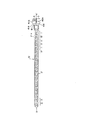
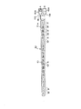
図1は、本実施の形態に係るミキシングチューブ10の平面図であり、図2は、図1に示すミキシングチューブ10のX−X’断面図である。このミキシングチューブ10は、流動性のある2種類の被混合材料A,Bを別々に収容する複数の被混合材料容器40A,40Bを装着し、これらの被混合材料容器40A,40Bから押し出された被混合材料A,Bを混合するためのものである。このミキシングチューブ10は、その全体が所定の力で押し潰すことが可能な軟質の熱可塑性樹脂によって形成されている。
FIG. 1 is a plan view of the mixing
また、このミキシングチューブ10は、2種類の第1通路ブロック11及び第2通路ブロック12が交互に且つ直列的に接続されている。その一端の第1通路ブロック11には、前記被混合材料容器40A,40Bと連結し被混合材料A,Bをミキシングチューブ10の変形通路へ注入する注入口18が設けられており、他端の第2通路ブロック12には、混合された被混合材料A,Bを吐出する吐出口19が設けられている。
The mixing
また、被混合材料容器40A,40Bは、ミキシングチューブ10の注入口18に接続するための接続部41A,41Bが設けられている。
The mixing
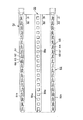
前記第1及び第2通路ブロック11,12の内部には、それぞれ混合用の変形通路13,14、及び、16,17が形成されている。これらの変形通路は、ミキシングチューブ10をその被混合材料の通過方向で縦に分割した第1外枠部材21及び第2外枠部材22により間に仕切り部材15を介して形成されている。図3は、ミキシングチューブ10を前記第1外枠部材21、第2外枠部材22、及び、仕切り部材15各部材に分解した平面図である。
Inside the first and second passage blocks 11 and 12,
第1外枠部材21は、第1通路ブロック11の変形通路13と第2通路ブロック12の変形通路16を形成する中空部を有しており、長手方向の両側端部には、第2外枠部材22及び仕切り部材15と溶着するためのつば部21aが設けられている。また、第2外枠部材22は、第1通路ブロック11の変形通路14と第2通路ブロック12の変形通路17を形成する中空部を有しており、長手方向の両側端部には、第1外枠部材21及び仕切り部材15と溶着するためのつば部22aが設けられている。仕切り部材15は、各通路ブロックの半分の大きさの穴部15cが一定間隔で設けられており、長手方向の両側端部には、第1及び第2外枠部材21,22と溶着するためのつば部15aが設けられている。
The first
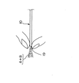
また、図4は、ミキシングチューブの第1及び第2ブロックを各変形通路ごと分解した斜視図である。第1通路ブロック11の変形通路13,14は、各々X方向に長い長方形の入口部13b,14bを有し、これらの入口部13b,14bを重ねて結合することにより、1個の正方形を成している。また、その出口部11bは正方形であり、2つの通路の間の仕切り部材15には穴部15cが設けられており、1個の出口部11bを形成している。
FIG. 4 is an exploded perspective view of the first and second blocks of the mixing tube for each deformed passage. Each of the
これらの変形通路13,14は、その断面形状及び断面積が入口点P1から出口点P5向かって連続的に変化しており、その中間点P3ではそれぞれ小辺の正方形になっている。また、入口点P1から中間点P3までは、変形通路13,14との間には仕切り部材15が介されており2つの変形通路13,14は分割されているが、中間点P3から出口点P5までは、変形通路13,14との間の仕切り部材15には穴部15cが設けられている。また、中間点P3から出口点P5までの間は、変形通路13,14はそれぞれ半分に分割され、一方の変形通路13d,14dは傾斜面を有している。そのため、変形通路13,14の断面積は、P3からP5にかけて徐々に大きくなる。すなわち、中間点P3か
ら出口点P5にかけて2つの変形通路13,14は徐々に合流し、出口部11bでは一個の正方形となる。
The cross-sectional shapes and cross-sectional areas of these
次いで、第2通路ブロックは、変形通路16,17を有しており、前記第1通路ブロックの変形通路13,14を逆に配置したものである。そして、第1通路ブロック11と第2通路ブロック12の接続部分では、上流側の第1通路ブロック11における変形通路13,14の出口部11bが、下流側の第2通路ブロックにおける変形通路16,17の入口部16b,17bに連通している。
Next, the second passage block has deformed
第1通路ロック11において混合された被混合材料A、Bは第2通路ブロック12の変形通路の入口部16b,17bに半分ずつに分割され、入口点Q1から中間点Q3までは各々の変形通路16,17内で被混合材料A,Bは混合される。また、第2通路ブロック12は、第1通路ブロック11と同様に中間点Q3から出口点Q5の間の仕切り部15には穴部15cが設けられているとともに、変形通路16,17は半分に分割され、一方の変形通路16d,17dは傾斜面を有している。そのため、中間点Q3から出口点Q5までの間に各々の変形通路16,17で混合された被混合材料A,Bが合流し混合する。この混合、分割手段を繰り返すことで、被混合材料A,Bは均一に混合される。
The materials A and B mixed in the
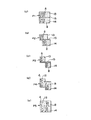
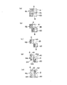
次いで、このように直列に接続された複数の第1及び第2通路ブロック11,12を被混合材料A,Bが通過する際の混合状態を説明する。図5には、第1通路ブロック11を被混合材料が通過する形態が示されている。なお、図5中の符号P1〜P5は、図5における第1通路ブロック11の材料通過位置に対応しており、それぞれの材料通過位置における入口部からみた断面図である。また、符号A,Bは被混合材料を示している。
Next, the mixing state when the materials to be mixed A and B pass through the plurality of first and second passage blocks 11 and 12 thus connected in series will be described. FIG. 5 shows a mode in which the material to be mixed passes through the
被混合材料容器40A,40Bから第1通路ブロック11に注入された被混合材料A,Bは、図5(a)に示すように、その入口点P1ではX方向に長い長方形に2分割される、そして徐々にX方向の長さが小さくなり(b)、中間点P3では、被混合材料A,Bが各々正方形に変化する(c)。その後、上述のように、変形通路13,14の間の仕切り部材15に穴部15cが設けられているため、変形通路13,14が徐々に合流し、被混合材料A,Bは合流する(d)。出口点P5では、変形通路13,14が完全に合流し、被混合材料A,Bは混在している(e)。
As shown in FIG. 5A, the mixed materials A and B injected into the
そして、第1通路ブロック11にて混合された被混合材料A,Bは、第2通路ブロック12の入口部において、X方向に長い長方形に2分割される。このようにして、2種類の被混合材料A,Bが実質的に合流及び分割される。従って、第1及び第2通路ブロック11,12の段数が多くなる程、被混合材料A,Bの分割、合流の回数が多くなるので、その混合度が高くなる。
Then, the materials A and B mixed in the
すなわち、このミキシングチューブ10は、2のN乗の理論で層を形成しているため、被混合材料A,Bを十分に混合することができる。また、被混合材料A,Bに対して強力な壁面抵抗から生ずるプラグ流を発生させることにより撹拌効果を生じさせることが可能である。
That is, since the mixing
次に、このミキシングチューブ10の製造方法を説明する。まず、第1外枠部材21、第2外枠部材22、仕切り部材15をそれぞれ成形する。第1及び第2外枠部材21,22は、各通路ブロック11,12の変形通路13,14,16,17となる中空部を有する形状で真空成形によって成形する。真空成形とは、板状のシート板を加熱された金型に真空吸引させて変形する成形方法である。尚、本実施の形態では、真空成形によって各部材を成形したが、所望の形状等を形成できる成型方法であれば、これに限られず種々の成型方法を用いることができる。仕切り部材15はシート状であり、ミキシングチューブ1
0の各通路ブロック11,12の半分の長さの穴部15cを設ける。このとき、第1外枠部材21、第2外枠部材22、及び、仕切り部材15のそれぞれには、長手方向の両端部につば部21a,22a,15aを設けておく。そして、第1外枠部材21と第2外枠部材22のつば部21a,22aで仕切り部材のつば部15aを挟み、この3部材のつば部21a,22a,15aの端部を溶着する。このようにして、本実施の形態に係るミキシングチューブ10ができる。
Next, a method of manufacturing the mixing
A
次いで、このミキシングチューブ10の使用方法を説明する。ミキシングチューブ10を用いて被混合材料A,Bを混合する場合には、図1に示すように、ミキシングチューブの注入口18に被混合材料容器40A,40Bの接続部41A,41Bを接続する。
Next, a method of using the mixing
次に、容器10A,10Bを後側から前側にかけて連続的に押し潰すことによって、それぞれの内部に収容されている被混合材料A,Bを絞り出す。このとき、被混合材料容器40A,40Bは所定の力が押し潰すことができるビニル又はシリコン等であるため、手で押し潰しても良いし、チューブ絞り器等の治具を用いても良い。この絞り出された被混合材料A,Bは、それぞれミキシングチューブ10の注入口18から1段目の第1通路ブロック11の変形通路13,14に注入される。
Next, the materials A and B to be mixed contained in the respective containers 10A and 10B are squeezed out by continuously crushing the containers 10A and 10B from the rear side to the front side. At this time, since the
このようにして第1通路ブロック11内に注入された被混合材料A,Bは、図6に示すように、ミキシングチューブ10を入口側から出口側にかけて連続的に押し潰すことにより、吐出口19から絞り出される。
The materials A and B to be mixed thus injected into the
このときには、上述のように第1及び第2ブロック11,12の変形通路13,14,16,17によって、被混合材料A,Bの分割と合流が繰り返されると共に、各変形通路13,14,16,17が押し潰されることにより、被混合材料A,Bに局部的に剪断力が作用し、結果として混合が十分に行われる。
At this time, as described above, the dividing and merging of the materials A and B to be mixed are repeated by the
また、図7に示すように、ミキシングチューブ10の吐出口19の先端まで完全に押し潰すことにより、内部の被混合材料A,Bを略完全に絞り出すことができ、ミキシングチューブ10内に残留することはなくなる。
Further, as shown in FIG. 7, by completely crushing the tip of the
このように、本発明のミキシングチューブ10は、所定の力、ここでは手の力で押し潰すことが可能な材料で形成することにより、ミキシングチューブ10を入口側から出口側にかけて連続的に押し潰すことによって、内部の被混合材料A,Bを十分に混合した状態で略完全に絞り出すことができる。
As described above, the mixing
なお、本実施の形態では、ミキシングチューブを手で押し潰したが、例えば、ミキシングチューブを両側面から狭持し連続的に押し潰すことができる治具等を用いると、効率的に被混合材料を混合することが可能となる。 In the present embodiment, the mixing tube is crushed by hand. For example, if a jig or the like that can hold the mixing tube from both sides and crush it continuously is used, the mixing material can be efficiently crushed. Can be mixed.
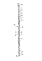
次いで、前記ミキシングチューブ10の各通路ブロック11,12の変形通路13,14,16,17をそれぞれ分割する中仕切り部を備えたミキシングチューブ30の一実施例を図面を基に説明する。図8は、本実施1に係るミキシングチューブ30の平面図である。このミキシングチューブ30は、前記ミキシングチューブと同様に流動性のある2種類の被混合材料A,Bを混合するためのものである。このミキシングチューブ30は、前記ミキシングチューブ10の変形通路13,14,16,17の変形させた実施例であり、その他の構成は同様であるため説明を省略する。
Next, an embodiment of the mixing
このミキシングチューブ30は、2種類の第1通路ブロック31及び第2通路ブロック
32が交互に且つ直列的に接続されている。前記第1及び第2通路ブロック31,32の内部には、それぞれ混合用の変形通路61,62,63,64及び、65,66,67,68が形成されている。これらの変形通路は、ミキシングチューブ30をその被混合材料の通過方向で縦に分割した第1外枠部材51及び第2外枠部材52とその間に介された仕切り部材35及び第1外枠部材51と第2外枠部材52にそれぞれ設けられた中仕切り部51b,51c,52b,52cにより形成されている。図9は、ミキシングチューブ30を前記第1外枠部材51、第2外枠部材52、及び、仕切り部材35の各部材に分解した平面図である。
In this mixing
第1外枠部材51は、第1通路ブロック31の変形通路61,62と第2通路ブロック32の変形通路65,66を形成する中空部を有しており、長手方向の両側端部には、第2外枠部材52及び仕切り部材35と溶着するためのつば部51aが設けられている。第1外枠部材51には、前記第1通路ブロック31を2つの変形通路61,62に分割するように、中仕切り部51bが形成されている。この中仕切り部51bは、第1通路ブロック31を分割するように第1外枠部材51を折り曲げて形成したものであり、中仕切り部51bを形成した部分の第1外枠部材51の断面形状は、略M字形である。また、この中仕切り部51bは、第1通路ブロック31の半分の長さに形成されており、第1通路ブロック31から隣接する第2通路ブロック32へ混合材料を吐出する際に2分割して吐出することができる。さらに、第1外枠部材51には、第2通路ブロック32においても2つの変形通路65,66を分割するように中仕切り部51cが形成されている。
The first
第2外枠部材52は、第1通路ブロック31の変形通路63,64と第2通路ブロック32の変形通路67,68を形成する中空部を有しており、長手方向の両側端部には、第1外枠部材51及び仕切り部材35と溶着するためのつば部52aが設けられている。また、前記第1外枠部材51と同様に、各変形通路を分割するための中仕切り部52b,52cが形成されている。前記仕切り部材35は、各通路ブロックの半分の大きさの穴部35cが一定間隔で設けられており、長手方向の両側端部には、第1及び第2外枠部材51,52と溶着するためのつば部35aが設けられている。
The second
図10は、ミキシングチューブ30の第1及び第2ブロック31,32を各変形通路ごと分解した斜視図である。第1通路ブロック31の入口部31aは正方形であり、X方向に長い長方形の変形通路61,63が重なり合って形成されている。また、第1通路ブロックの出口部31bも正方形であり、4つの変形通路61,62,63,64によって形成されている。この出口部31bにおいて、2つの通路の間の仕切り部材35には穴部35cが設けられており、この4つの変形通路は、Y方向において隣り合う変形通路がそれぞれ連通している。すなわち、変形通路62と変形通路63及び変形通路61と変形通路64が連通しY方向に長い長方形の通路を形成している。
FIG. 10 is an exploded perspective view of the first and
前記入口部31aを形成する変形通路61,63は、その断面形状及び断面積が入口点R1から出口点R5向かって連続的に変化しており、その中間点R3ではそれぞれ小辺の正方形になっており出口部まで同形状である。中間点R3からR5までは、各外枠部材51,52には中仕切り部51b,52bが形成されており、変形通路61,63に隣接して、変形通路62,64が形成されている。この変形通路62,64は傾斜面を有しており、その断面積はR3からR5にかけて徐々に大きくなる。また、R3からR5までは、仕切り部材35に穴部35cが形成されているため、Y方向に隣接する変形通路62と63及び変形通路61と64は出口部で合流する。
The cross-sectional shape and cross-sectional area of the
次いで、第2通路ブロック32は、変形通路65,66,67,68を有しており、第1通路ブロック31の各外枠部材の変形通路をY方向を中心として反転させたものである。そして、第1通路ブロック31と第2通路ブロック32の接続部分では、上流側の第1
通路ブロック31の変形通路61,62が下流側の第2通路ブロック32の変形通路65に連通しており、第1通路ブロック31の変形通路63,64が第2通路ブロック32の変形通路67と連通している。
Next, the
The
このように構成されたミキシングチューブ30によれば、第1通路ブロック31において混合された被混合材料A、Bは第2通路ブロック32の変形通路65,67に半分ずつに分割され、入口点S1から中間点S3までは各々の変形通路65,67内で被混合材料A,Bは混合される。そして、中間点S3から出口点S5では、変形通路65と変形通路68、変形通路67と変形通路66がそれぞれ出口部で合流し、被混合材料A,Bは混合される。この混合、分割手段を繰り返すことで、被混合材料A,Bは均一に混合される。
According to the mixing
次いで、このように直列に接続された複数の第1及び第2通路ブロック31,32を被混合材料A,Bが通過する際の混合状態を説明する。図11には、第1通路ブロック31を被混合材料が通過する形態が示されている。なお、図11中の符号R1〜R5は、図10における第1通路ブロック31の材料通過位置に対応しており、それぞれの材料通過位置における入口部からみた断面図である。また、符号A,Bは被混合材料を示している。
Next, the mixing state when the materials to be mixed A and B pass through the plurality of first and second passage blocks 31 and 32 thus connected in series will be described. FIG. 11 shows a mode in which the material to be mixed passes through the
被混合材料容器40A,40Bから第1通路ブロック31に注入された被混合材料A,Bは、図11(a)に示すように、その入口点R1ではX方向に長い長方形の変形通路61,63に2分割される、そして徐々にX方向の長さが短くなり(b)、中間点P3では、被混合材料A,Bが各々正方形となる(c)。その後、変形通路61と変形通路64、変形通路62と変形通路63とが各々徐々に合流して、被混合材料A,Bが混合される(d)。出口点P5では、変形通路61と変形通路64、変形通路62と変形通路は、それぞれY方向に長い長方形の出口部31bを形成する(e)。
As shown in FIG. 11 (a), the mixed materials A and B injected from the
そして、第1通路ブロック31にて混合された被混合材料A,Bは、第2通路ブロック32の入口部32aにおいて、X方向に長い長方形の変形通路65,67に2分割される。このようにして、2種類の被混合材料A,Bが実質的に合流及び分割される。従って、第1及び第2通路ブロック31,32の段数が多くなる程、被混合材料A,Bの分割、合流の回数が多くなるので、その混合度が高くなる。すなわち、このミキシングチューブ30は、2のN乗の理論で層を形成しているため、被混合材料A,Bを十分に混合することができる。
The materials A and B mixed in the
次に、このミキシングチューブ30の製造方法を説明する。まず、第1外枠部材51、第2外枠部材52、仕切り部材35をそれぞれ成形する。第1及び第2外枠部材51,52は、中仕切り部51b,51c,52b,52cを形成しつつ、各通路ブロック31,32の変形通路を有する形状で成形する。仕切り部材35はシート状であり、ミキシングチューブ30の各通路ブロック31,32の半分の長さの穴部35cを設ける。このとき、第1外枠部材51、第2外枠部材52、及び、仕切り部材35のそれぞれには、長手方向の両端部につば部51a,52a,35aを設けておく。そして、第1外枠部材51と第2外枠部材52のつば部51a,52aで仕切り部材35のつば部35aを挟み、この3部材のつば部51a,52a,35aの端部を溶着するとともに、第1外枠部材51の中仕切り部51b,51cと第2外枠部材52の中仕切り部52b,52cを溶着する。このようにして、本実施例1に係るミキシングチューブ30を製造することができる。
Next, a method of manufacturing the mixing
次いで、前記ミキシングチューブ30の仕切り部材35に第1外枠部材51と第2外枠部材52の中仕切り部51b,51c,52b,52cと当接する係合部35dを設けたミキシングチューブの一実施例を図面を基に説明する。実施例2に係るミキシングチューブは、仕切り部材35の形状と、製造方法のみ実施例1に係るミキシングチューブ30と
異なっており、完成したミキシングチューブの外形及びその他の構成は同様であるため、実施例1と同様の符号を用いて説明を省略する。
Next, one embodiment of the mixing tube in which the
図12は、実施例2に係るミキシングチューブを第1外枠部材51、第2外枠部材52、及び、仕切り部材35の各部材に分解した平面図である。前記実施例1では、仕切り部材35は一枚であるが、本実施例2では仕切り部材35は2枚であり、各々の仕切り部材35の穴部35cには、第1外枠部材51の中仕切り部51b,51cと第2外枠部材52の中仕切り部52b,52cと当接する係合部35dが設けられている。
FIG. 12 is a plan view in which the mixing tube according to the second embodiment is disassembled into a first
次に、このミキシングチューブの製造方法を説明する。まず、第1外枠部材51、第2外枠部材52、2枚の仕切り部材35をそれぞれ成形する。第1及び第2外枠部材51,52は、中仕切り部51b,51c,52b,52cを形成しつつ、各通路ブロック31,32の変形通路を有する形状で成形する。仕切り部材35はシート状であり、前記中仕切り部51b,51c,52b,52cと当接する係合部35dを残しつつ、ミキシングチューブの各通路ブロック31,32の半分の長さの穴部35cを設ける。このとき、第1外枠部材51、第2外枠部材52、及び、仕切り部材35のそれぞれには、長手方向の両端部につば部51a,52a,35aを設けておく。そして、第1外枠部材51のつば部51aと2枚のうちの1枚の仕切り部材35のつば部35aを溶着する。また、もう一枚の仕切り部材35のつば部35aと第2外枠部材52のつば部52aを溶着する。次いで、ぞれぞれ各外枠部材と溶着した2枚の仕切り部材35を溶着する。このようにして、各変形通路を分割する中仕切り部を形成しつつミキシングチューブを製造することができる。尚、本実施例2では、各外枠部材51,52と仕切り部材35のつば部51a,52a,35a同士のみを溶着したが、つば部51a,52a,35a同士のみならず各外枠部材51,52の中仕切り部51b,51c,52b,52cと仕切り部材35の係合部35dとを合わせて溶着しても良い。
Next, a method of manufacturing the mixing tube will be described. First, the first
尚、本実施の形態では、第1及び第2通路ブロックの断面積及び断面形状は、いずれも連続的に変化しているが、本発明に係るミキシングチューブ10,30はこれに限られず、断面形状又は断面積のいずれか一方が連続的に変化し、通過する被混合材料に圧縮及び剪断力を作用させる形状であっても良い。
In the present embodiment, the cross-sectional areas and the cross-sectional shapes of the first and second passage blocks are both continuously changed. However, the mixing
10,30 ミキシングチューブ
11,31 第1通路ブロック
12,32 第2通路ブロック
13,14,16,17,61,62,63,64 変形通路
15,35 仕切り部材
18 注入口
19 吐出口
21,51 第1外枠部材
22,52 第2外枠部材
51b,51c,52b,52c 中仕切り部
40A,40B 被混合材料容器
A,B 被混合材料
10, 30
Claims (9)
前記第1及び第2混合用通路は、前記ミキシングチューブをその被混合材料の通過方向で縦に分割した第1及び第2外枠部材とその間の1枚の仕切り部材を介して形成されており、
前記仕切り部材には、前記被混合材料の混合方向の一定間隔毎に各エレメントの半分の長さの穴部が設けられ、この穴部により第1混合用通路と第2混合用通路とが分割及び集合を繰り返し、通過する被混合材料に分割及び集合を繰り返し作用させることを特徴とするミキシングチューブ。 It has first and second mixing passages in which a plurality of elements having continuously changing cross-sectional shapes are connected in series, and a plurality of types of materials to be mixed are passed through the first and second mixing passages. A mixing tube that divides the material to be mixed in the process and repeatedly acts assembling,
The first and second mixing passages are formed via first and second outer frame members which vertically divide the mixing tube in the direction of passage of the material to be mixed, and one partition member therebetween. ,
The partition member is provided with a hole having a half length of each element at regular intervals in the mixing direction of the materials to be mixed, and the hole divides the first mixing passage and the second mixing passage. A mixing tube, wherein the mixing tube is repeatedly operated to perform the division and the assembly on the material to be mixed that passes.
前記仕切り部材の穴部において、第1外枠部材の中仕切り部と第2外枠部材の中仕切り部が溶着していることを特徴とする請求項1に記載のミキシングチューブ。 The first outer frame member and the second outer frame member are each formed with an intermediate partition that divides the first mixing passage and the second mixing passage, respectively.
2. The mixing tube according to claim 1, wherein a middle partition portion of the first outer frame member and a middle partition portion of the second outer frame member are welded in the hole of the partition member. 3.
この第1外枠部材の中仕切り部と第2外枠部材の中仕切り部は、それぞれ前記仕切り部材と溶着していることを特徴とする請求項1又は請求項2に記載のミキシングチューブ。 The first outer frame member and the second outer frame member are each formed with an intermediate partition that divides the first mixing passage and the second mixing passage, respectively.
The mixing tube according to claim 1, wherein the middle partition portion of the first outer frame member and the middle partition portion of the second outer frame member are welded to the partition member, respectively.
前記仕切り部材のつば部が前記第1外枠部材と第2外枠部材のつば部に狭持されていることにより、前記第1外枠部材、第2外枠部材、及び、仕切り部材は一体化し、前記第1及び第2混合用通路を形成していることを特徴とする請求項1から請求項4のいずれかに記載のミキシングチューブ。 The first outer frame member, the second outer frame member, and a joining portion to which each of the partition members is joined are provided with a flange portion on the outside thereof along the first and second mixing paths, respectively. Yes,
The first outer frame member, the second outer frame member, and the partition member are integrally formed by the flange portion of the partition member being sandwiched between the first outer frame member and the second outer frame member. 5. The mixing tube according to claim 1, wherein the mixing tube is formed to form the first and second mixing passages. 6.
前記第1外枠部材のつば部と前記仕切り部材のつば部を溶着する第1の工程と、
前記第2外枠部材のつば部と前記仕切り部材のつば部を溶着する第2の工程と、
前記第1の工程と第2の工程で製造された部材のつば部同士を溶着する第3の工程と、を備えることを特徴とする請求項5に記載のミキシングチューブの製造方法。 The first outer frame member and the second outer frame member made of a thermoplastic resin are molded while providing an intermediate partition for dividing the first mixing passage and the second mixing passage, respectively, and a thermoplastic resin is formed. After forming a hole portion while providing an engaging portion in the partition member that is in contact with the middle partition portion of the first outer frame member and the second outer frame member,
A first step of welding the flange of the first outer frame member and the flange of the partition member;
A second step of welding the flange of the second outer frame member and the flange of the partition member;
The method for manufacturing a mixing tube according to claim 5, further comprising a third step of welding the flange portions of the members manufactured in the first step and the second step.
前記第1外枠部材のつば部と前記仕切り部材のつば部を溶着するとともに、第1外枠部材の中仕切り部と仕切り部材の係合部を溶着する第1の工程と、
前記第2外枠部材のつば部と前記仕切り部材のつば部を溶着するとともに、第2外枠部材の中仕切り部と仕切り部材の係合部を溶着する第2の工程と、
前記第1の工程と第2の工程で製造された部材のつば部同士を溶着する第3の工程と、を備えることを特徴とする請求項5に記載のミキシングチューブの製造方法。 The first outer frame member and the second outer frame member made of a thermoplastic resin are molded while providing an intermediate partition for dividing the first mixing passage and the second mixing passage, respectively, and a thermoplastic resin is formed. After forming a hole portion while providing an engaging portion in the partition member that is in contact with the middle partition portion of the first outer frame member and the second outer frame member,
A first step of welding the brim portion of the first outer frame member and the brim portion of the partition member, and welding a middle partition portion of the first outer frame member and an engaging portion of the partition member;
Welding a flange portion of the second outer frame member and a flange portion of the partition member, and welding a middle partition portion of the second outer frame member and an engagement portion of the partition member;
The method for manufacturing a mixing tube according to claim 5, further comprising a third step of welding the flange portions of the members manufactured in the first step and the second step.
Priority Applications (2)
| Application Number | Priority Date | Filing Date | Title |
|---|---|---|---|
| JP2003383664A JP2004249282A (en) | 2003-01-30 | 2003-11-13 | Mixing tube and its manufacturing method |
| US10/767,753 US7284902B2 (en) | 2003-01-30 | 2004-01-29 | Mixing tube and method of manufacturing the mixing tube |
Applications Claiming Priority (2)
| Application Number | Priority Date | Filing Date | Title |
|---|---|---|---|
| JP2003022098 | 2003-01-30 | ||
| JP2003383664A JP2004249282A (en) | 2003-01-30 | 2003-11-13 | Mixing tube and its manufacturing method |
Publications (2)
| Publication Number | Publication Date |
|---|---|
| JP2004249282A true JP2004249282A (en) | 2004-09-09 |
| JP2004249282A5 JP2004249282A5 (en) | 2006-09-21 |
Family
ID=33032202
Family Applications (1)
| Application Number | Title | Priority Date | Filing Date |
|---|---|---|---|
| JP2003383664A Pending JP2004249282A (en) | 2003-01-30 | 2003-11-13 | Mixing tube and its manufacturing method |
Country Status (2)
| Country | Link |
|---|---|
| US (1) | US7284902B2 (en) |
| JP (1) | JP2004249282A (en) |
Cited By (1)
| Publication number | Priority date | Publication date | Assignee | Title |
|---|---|---|---|---|
| JP2020528386A (en) * | 2017-06-06 | 2020-09-24 | シンエツ シリコーンズ ヨーロッパ ベスローテン フェンノートシャップShin−Etsu Silicones Europe B.V. | Containers and dispensers for viscous materials |
Families Citing this family (8)
| Publication number | Priority date | Publication date | Assignee | Title |
|---|---|---|---|---|
| EP1745841A1 (en) * | 2004-04-30 | 2007-01-24 | Maeda Corporation | Mixing sheet |
| US7537139B2 (en) * | 2005-05-27 | 2009-05-26 | Henkel Corporation | Dual chamber piston pressure pack dispenser system |
| JP2007090138A (en) * | 2005-09-27 | 2007-04-12 | Yokogawa Electric Corp | Cartridge for chemical treatments, and its using method |
| US20090038701A1 (en) | 2006-01-17 | 2009-02-12 | Baxter International Inc. | Device, system and method for mixing |
| DE102006060589B3 (en) * | 2006-12-21 | 2008-06-12 | Anestis Savidis | Disposable repairing set for formation of gel cushion as optical coupling medium between pane of vehicle and sensor housing, has production body, which contains source substance for coupling medium |
| US7985020B2 (en) * | 2009-09-25 | 2011-07-26 | Nordson Corporation | Cross flow inversion baffle for static mixer |
| CN103492278A (en) * | 2011-04-21 | 2014-01-01 | 高露洁-棕榄公司 | Dispenser with rupture member |
| US9572555B1 (en) * | 2015-09-24 | 2017-02-21 | Ethicon, Inc. | Spray or drip tips having multiple outlet channels |
Family Cites Families (16)
| Publication number | Priority date | Publication date | Assignee | Title |
|---|---|---|---|---|
| NL244295A (en) | 1959-10-13 | |||
| BE754657Q (en) | 1965-11-29 | 1971-01-18 | Kenics Corp | MIXER APPLIANCE |
| US3476521A (en) * | 1967-01-20 | 1969-11-04 | Joseph T Wise | Polymerizing apparatus |
| US3927868A (en) * | 1974-05-28 | 1975-12-23 | Thomas B Moore | Static-type mixer, and receptacle and method of packaging utilizing same |
| US4002289A (en) * | 1974-05-28 | 1977-01-11 | Moore Thomas B | Static-type mixer and receptacle |
| US4130245A (en) * | 1977-09-29 | 1978-12-19 | Will Ross, Inc. | Liquid dispensing package |
| US4538920A (en) | 1983-03-03 | 1985-09-03 | Minnesota Mining And Manufacturing Company | Static mixing device |
| US4952068A (en) * | 1989-03-21 | 1990-08-28 | Flint Theodore R | Static mixing device and container |
| US5154321A (en) * | 1991-01-15 | 1992-10-13 | John Shomer | Dispensing container for multi-component curable compositions |
| US5516209A (en) * | 1994-11-15 | 1996-05-14 | Flint; Theodore R. | Disposable static mixing device with a reusable housing |
| JPH09253467A (en) | 1996-03-20 | 1997-09-30 | Maeda Corp | Kneading and kneading device |
| US5826981A (en) * | 1996-08-26 | 1998-10-27 | Nova Biomedical Corporation | Apparatus for mixing laminar and turbulent flow streams |
| JP2000000452A (en) | 1998-06-17 | 2000-01-07 | Maeda Corp | Vertical kneader |
| JP3171828B2 (en) | 1998-09-02 | 2001-06-04 | 前田建設工業株式会社 | Kneading device |
| US6135632A (en) * | 1999-06-16 | 2000-10-24 | Flint; Theodore R. | Disposable static mixing device having check valve flaps |
| JP3786851B2 (en) | 2001-06-22 | 2006-06-14 | 前田建設工業株式会社 | Mixing tube |
-
2003
- 2003-11-13 JP JP2003383664A patent/JP2004249282A/en active Pending
-
2004
- 2004-01-29 US US10/767,753 patent/US7284902B2/en not_active Expired - Fee Related
Cited By (2)
| Publication number | Priority date | Publication date | Assignee | Title |
|---|---|---|---|---|
| JP2020528386A (en) * | 2017-06-06 | 2020-09-24 | シンエツ シリコーンズ ヨーロッパ ベスローテン フェンノートシャップShin−Etsu Silicones Europe B.V. | Containers and dispensers for viscous materials |
| JP7316944B2 (en) | 2017-06-06 | 2023-07-28 | シンエツ、シリコーンズ、ヨーロッパ、ベスローテン、フェンノートシャップ、ツバイヒニーダーラッスング、ドイチュラント | Containers and dispensers for viscous materials |
Also Published As
| Publication number | Publication date |
|---|---|
| US20040195266A1 (en) | 2004-10-07 |
| US7284902B2 (en) | 2007-10-23 |
Similar Documents
| Publication | Publication Date | Title |
|---|---|---|
| JP3746766B2 (en) | Emulsion production method and apparatus | |
| US6890093B2 (en) | Multi-stream microfludic mixers | |
| JP2004249282A (en) | Mixing tube and its manufacturing method | |
| US6935772B2 (en) | Fluidic mixer in microfluidic system | |
| US6773156B2 (en) | Method and apparatus for reducing fluid streaking in a motionless mixer | |
| JP5889346B2 (en) | Static mixer | |
| JP3634868B2 (en) | Micro mixer | |
| US20030133358A1 (en) | Multi-stream microfluidic aperture mixers | |
| US20090092526A1 (en) | Micro-channels, micro-mixers, and micro-reactors | |
| JPH09506034A (en) | Static micro mixer | |
| JPH1057791A (en) | Static agitator having assembly of plural chamber strings | |
| US20090246086A1 (en) | Microfluidic network and method | |
| CN101678293A (en) | Microfluidic self-sustaining oscillating mixers and devices and methods utilizing same | |
| EP0747195B1 (en) | A method for assembling a control panel of an electronic apparatus | |
| DE10153706A1 (en) | Using ultrasound in injection molding cavities, comprises directing ultrasound at critical cavity points using a system comprising a transducer, booster and a sonotrode | |
| JP2004249282A5 (en) | ||
| JP4284841B2 (en) | Liquid mixer | |
| KR20120025020A (en) | Micro mixer and method for fabricating thereof | |
| JPWO2005105280A1 (en) | Mixing sheet | |
| JP4176683B2 (en) | Microcapsule manufacturing method and apparatus | |
| JP2003001078A (en) | Mixing tube | |
| JP4306243B2 (en) | Particle production method | |
| JP2004351302A (en) | Vessel having built-in mixer and its fabricating method | |
| JP4043666B2 (en) | Kneading nozzle | |
| KR100558830B1 (en) | Microfluidic mixer and manufacturing method thereof |
Legal Events
| Date | Code | Title | Description |
|---|---|---|---|
| A521 | Written amendment |
Free format text: JAPANESE INTERMEDIATE CODE: A523 Effective date: 20060807 |
|
| A621 | Written request for application examination |
Free format text: JAPANESE INTERMEDIATE CODE: A621 Effective date: 20060807 |
|
| A711 | Notification of change in applicant |
Free format text: JAPANESE INTERMEDIATE CODE: A711 Effective date: 20080528 |
|
| A977 | Report on retrieval |
Free format text: JAPANESE INTERMEDIATE CODE: A971007 Effective date: 20081020 |
|
| A131 | Notification of reasons for refusal |
Free format text: JAPANESE INTERMEDIATE CODE: A131 Effective date: 20081028 |
|
| A02 | Decision of refusal |
Free format text: JAPANESE INTERMEDIATE CODE: A02 Effective date: 20090310 |