JP2004245444A - Built-in cooking stove - Google Patents
Built-in cooking stove Download PDFInfo
- Publication number
- JP2004245444A JP2004245444A JP2003033500A JP2003033500A JP2004245444A JP 2004245444 A JP2004245444 A JP 2004245444A JP 2003033500 A JP2003033500 A JP 2003033500A JP 2003033500 A JP2003033500 A JP 2003033500A JP 2004245444 A JP2004245444 A JP 2004245444A
- Authority
- JP
- Japan
- Prior art keywords
- side molding
- molding
- built
- appliance
- stored
- Prior art date
- Legal status (The legal status is an assumption and is not a legal conclusion. Google has not performed a legal analysis and makes no representation as to the accuracy of the status listed.)
- Granted
Links
Images





Landscapes
- Combinations Of Kitchen Furniture (AREA)
Abstract
Description
【0001】
【発明の属する技術分野】
本発明は、キッチンユニットのカウンタトップに形成された上面開口に器具本体を上部から組み込むビルトインこんろに関する。
【0002】
【従来の技術】
従来から、キッチンユニットのカウンタに一体で収納したビルトインこんろが知られている。このようなビルトインこんろ101では、図8,9に示すように、カウンタトップ102に設けた上面開口103より器具を落とし込み左右に張り出した器具の上端109をカウンタトップ102に引っ掛けることにより係止すると共に、器具前面をカウンタ前面104に設けた前面開口105にはめ込む。
この際、器具の横幅と前面開口105の横幅とに寸法差があり、器具を単に落とし込んで収納しただけでは、器具前面の左右と前面開口105との間に隙間Sが生じキッチンユニット素材がむきだしとなってしまうため、収納後さらに左右の隙間Sに正面より化粧板107(以下、サイドモール107と呼ぶ)を取り付ける。尚、前面開口105と上面開口103の横幅は規格で決まっており、前面開口105の方が上面開口103よりも横幅は大きい。このために、器具の横幅は、どうしても前面開口105の横幅よりも小さくなってしまう。
そして、特許文献1や特許文献2には、サイドモールの取り付けや取り外しが確実かつ簡単に行え、更に取り外しの際にサイドモールが変形しにくいビルトインこんろが提案されている。
【0003】
【特許文献1】
特開平9−280574号公報
【特許文献2】
特開平10−110957号公報
【0004】
【発明が解決しようとする課題】
しかしながら、上述したようなビルトインこんろでは、いずれも、サイドモールを後付け部品として、本体梱包に同封しているため、紛失や欠品(未入梱)という問題があった。また、取り付けを容易にしているといっても、差し込みツメ折れ等の施工時の破損も依然として問題であった。更に、サイドモールを隙間内に落としてしまうこともあり、こうした場合では、落としたサイドモールを拾うために、器具本体をわざわざカウンタから取り外さねばならなかった。
本発明のビルトインこんろは上記課題を解決し、サイドモールの紛失や欠品をなくすとともに、施工性を向上させることを目的とする。
【0005】
【課題を解決するための手段】
上記課題を解決する本発明の請求項1記載のビルトインこんろは、
キッチンユニットのカウンタトップに形成された上面開口に器具本体を上部から組み込んでカウンタ前面に形成された前面開口に器具前面をはめ込み、器具前面の左右と該前面開口との間に生じた隙間をサイドモールによって塞ぐビルトインこんろにおいて、
上記サイドモールは、器具本体の前面左右に設けられた収納部に収納されており、器具本体設置後に、該収納部から露出させて上記隙間を塞ぐことを要旨とする。
【0006】
また、本発明の請求項2記載のビルトインこんろは、上記請求項1記載のビルトインこんろにおいて、
上記サイドモールを器具前面の左右と上記前面開口との間に生じた隙間を塞ぐ方向に押圧する弾性体を備えたことを要旨とする。
【0007】
上記構成を有する本発明の請求項1記載のビルトインこんろは、カウンタトップに形成された上面開口に器具全体を上部から組み込んでカウンタ前面に形成された前面開口に器具前面をはめ込み、その後、器具本体の前面左右の収納部に収納されているサイドモールを露出させて、器具前面の左右と前面開口との間を塞いで外観を良くする。
そして、サイドモールは、収納部に収納されて器具本体と一体的に形成されているため、従来のように別部材としている場合と違い、紛失や欠品(未入梱)といった問題は生じない。
【0008】
また、本発明の請求項2記載のビルトインこんろは、弾性体の付勢力によってサイドモールが収納部から器具前面の左右と前面開口との間に生じた隙間を塞ぐ方向に移動する。このため、収納部からサイドモールを露出させることが容易となり、施工性が向上する。更に、サイドモールは常に隙間を塞ぐ方向に押圧されるため、閉成状態が確実に維持される。
【0009】
【発明の実施の形態】
以上説明した本発明の構成・作用を一層明らかにするために、以下本発明のビルトインこんろの好適な実施形態について説明する。
【0010】
図5に示すように、本実施形態のビルトインこんろ1においては、キッチンユニットのカウンタトップ2に形成した四角形の上面開口3に器具本体を落とし込み器具本体の上端9をカウンタトップ2に引っ掛けて係止させると、カウンタ前面4に形成した前面開口5に器具前面がはまり込んで、操作パネル面6が前面開口5から顔を出す。器具本体をカウンタに組み込んだ後に、器具前面の左右に設けられた収納部8に収納されたサイドモール7を取り出して、器具前面の左右と前面開口5との間の隙間を塞ぐ。
【0011】
ここで、サイドモール7の収納部8及び収納部8からの露出方法について説明する。
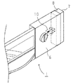
図1,2に示すように、器具前面左右の側面には収納部8が設けられ、この収納部8には、スライド式のサイドモール7が収納される。サイドモール7は、図1に示す収納状態において、横から軽く一回矢印方向に押して手を放すとロックが外れ、反対方向にスライドして図2に示すように、収納部8から飛び出しモール突出状態となり器具前面の左右と前面開口5との間の隙間を塞ぐ。
図2のモール突出状態時に横からサイドモール7を収納部8に押し込むと、サイドモール7はスライドしていって収納部8に入りそこで固定される。
【0012】
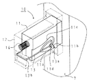
このような押し操作の繰り返しによる収納状態とモール突出状態との繰り返しは、周知のハートカム機構10により達成される。ハートカム機構10は、収納部8内でサイドモール7と一体的に形成される。
ハートカム機構10について図3,4を用いて簡単に説明する。尚、図3はサイドモール7が収納されている時の説明図であり、図4はサイドモール7がモール突出状態の時の説明図である。
ハートカム機構10は、サイドモール7と一体に形成され略ハート形状等の複数の突起を備えたガイド部11と、収納部8内に固定されガイド部11のケーシングとなる箱体12(図3,4中においては、箱体12は点線で描いている)と、先端屈曲部13aをガイド部11との係合部とし基端屈曲部13bが箱体12に支持された係合ピン13と、ガイド部11、すなわちサイドモール7をモール突出状態側に付勢する付勢バネ14とからなる。
ガイド部11は、中央の略ハート形状の第一突起11aと、この第一突起11aと所定の間隔をおいて形成された第二突起11bと、第三突起11cとを備える。第一突起11aには、サイドモール7の収納時において、係合ピン13の先端屈曲部13aを係止させる係止部11dが形成される。
【0013】
係合ピン13の先端屈曲部13aが係止部11dに係止されている状態(サイドモール7の収納時)で、サイドモール7を付勢バネ14の付勢力に反して軽く押すと、先端屈曲部13aと係止部11dとの係止が外れる。この状態で手をはなすと先端屈曲部13aは第二突起11bに導かれて第一突起11aの下側に移動する。ガイド部11は付勢バネ14によって、モール突出方向(図面右側)に付勢されているため、先端屈曲部13aと係止部11dとの係止が外れるとサイドモール7は、モール突出位置に自動的に移動する。この際、係合ピン13の先端屈曲部13aは、第一突起11aの下側を通過する。
一方、サイドモール7をモール突出状態から収納部8へ収納する場合は、モール突出状態のサイドモール7を付勢バネ14の付勢力に逆らって、収納部8に押し込んでいくと、係合ピン13の先端屈曲部13aは第一突起11aと第三突起11cとの間を通過していく。そして、終端位置まで押し込んで手をはなすと先端屈曲部13aが第一突起11aの係止部11dに係止されてサイドモール7は収納状態となる。
【0014】
上述したビルトインこんろ1によれば、サイドモール7を器具前面左右の側面に設けた収納部8に収納して器具本体と一体的に形成しているため、従来のように別部品としている場合と違い、紛失や欠品(未入梱)といった問題は生じない。
更に、サイドモール7は、器具取付時には、収納部8に収納されているため、器具本体の横幅を、上面開口3や前面開口5よりも小さく形成でき、従来と同様に取付作業の邪魔にならない。
【0015】
また、ワンタッチでサイドモール7を収納部8から取り出して、器具前面の左右と前面開口5との間の隙間を塞ぐことができ、施工性能が向上する。しかも、このようなサイドモール7の取り出しは、横から軽く一回押すだけなので、従来のように取り付けの際にサイドモール7を壊してしまったり、隙間に落としてしまうといった不都合も生じない。しかも、ビルトインこんろ1を取り外す場合には、サイドモール7を横から押し込むだけで簡単に収納できる。
更に、サイドモール7は付勢バネ14によって隙間方向に、常に押圧されているため、モール突出状態を確実に維持できる。また、付勢バネ14に押圧されたサイドモール7のスライドストロークを充分確保することにより、サイドモール7の側面が前面開口5の側面に確実に当接し、常に隙間をぴったりと閉じることができ見栄えが良い。
【0016】
以上本発明の実施形態について説明したが、本発明はこうした実施形態に何等限定されるものではなく、本発明の要旨を逸脱しない範囲において、種々なる態様で実施し得ることは勿論である。
例えば、本実施形態では、サイドモール7を収納部8からスライド移動させて露出させるようにしているが、これに限ったものではなく、図6,7に示すように、回転移動によって露出させるように構成しても構わない。
【0017】
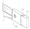
この例のビルトインこんろ201では、器具前面の左右に設けられた軸220にサイドモール207が回動自在に軸支され、このサイドモール207が図示しないトルクバネによって、図6に示すように、隙間閉塞側(矢印方向)に付勢される。サイドモール207の裏面には、図示しないマグネットプレートが取り付けられており、このマグネットプレートの磁石の力でサイドモール207は器具側面(鉄板)にくっついて収納状態となる(図6)。
サイドモール207を取り出す場合は、隙間に指を入れて磁石の力よりも大きな力でサイドモール207を器具側面からはがすと、サイドモール207は、トルクバネの付勢力によって軸220を中心に回転移動する。そして、図示しないストッパにより回転移動が所定の位置(器具前面と同一平面上となる位置)で止められ、図7に示すようなモール突出状態となり器具前面と前面開口5との間の隙間を塞ぐ。
一方、サイドモール207を収納する場合は、トルクバネの付勢力に逆らって、サイドモール207を奥に押し込んでいくと、マグネットプレートの磁石の力によって、サイドモール207は器具側面にくっついて収納される。
また、上述した例では、磁石の力を用いてサイドモール207を器具側面に収納する例を示したが、これに限ったものではなく、例えば、周知のプッシュプッシュ機構を用いてサイドモール207を器具側面に収納するようにしても構わない。
【0018】
【発明の効果】
以上詳述したように、本発明の請求項1記載のビルトインこんろによれば、サイドモールを収納部に収納して器具本体と一体的に形成しているため、従来のように別部材としている場合と違い、紛失や欠品(未入梱)といった問題は生じない。
【0019】
更に、本発明の請求項2記載のビルトインこんろによれば、サイドモールは収納部から弾性体の付勢力によって露出するため、手で器具前面の左右と前面開口との間の隙間にはめ込む必要がなく、施工性が向上する。
しかも、サイドモールは、常に隙間を塞ぐ方向に押圧されるため、閉成状態が確実に維持される。
【図面の簡単な説明】
【図1】本実施形態としてのサイドモールのスライド移動を説明する図である(サイドモール収納時)。
【図2】本実施形態としてのサイドモールのスライド移動を説明する図である(サイドモール突出時)。
【図3】本実施形態としてのハートカム機構を説明する図である(サイドモール収納時)。
【図4】本実施形態としてのハートカム機構を説明する図である(サイドモール突出時)。
【図5】本実施形態としてのビルトインこんろをカウンタに組み込んだ状態を説明する図である。
【図6】別の実施形態としてのサイドモールの回転移動を説明する図である(サイドモール収納時)。
【図7】別の実施形態としてのサイドモールの回転移動を説明する図である(サイドモール突出時)。
【図8】従来例としてのビルトインこんろをカウンタに組み込んだ状態を説明する図である。
【図9】従来例としてのビルトインこんろの概略構成図である。
【符号の説明】
1…ビルトインこんろ、2…カウンタトップ、3…上面開口、4…カウンタ前面、5…前面開口、7…サイドモール、8…収納部、14…付勢バネ。[0001]
TECHNICAL FIELD OF THE INVENTION
TECHNICAL FIELD The present invention relates to a built-in stove in which an appliance main body is incorporated from above into a top opening formed in a countertop of a kitchen unit.
[0002]
[Prior art]
2. Description of the Related Art A built-in stove integrally housed in a counter of a kitchen unit has been known. In such a built-
At this time, there is a dimensional difference between the width of the utensil and the width of the
[0003]
[Patent Document 1]
JP 9-280574 A [Patent Document 2]
JP-A-10-110957
[Problems to be solved by the invention]
However, in any of the built-in stoves described above, since the side molding is enclosed as a retrofit part in the main body packaging, there is a problem that the stove is lost or missing (not packed). In addition, even if the mounting is facilitated, breakage at the time of construction such as breakage of the insertion nail still remains a problem. Further, the side molding may be dropped into the gap. In such a case, the appliance body must be removed from the counter in order to pick up the dropped side molding.
The built-in stove of the present invention solves the above-mentioned problems, and aims to eliminate loss or shortage of the side molding and improve workability.
[0005]
[Means for Solving the Problems]
The built-in stove according to
The appliance main body is assembled from the top into the upper opening formed in the counter top of the kitchen unit, the front of the appliance is fitted into the front opening formed in the front of the counter, and the gap formed between the left and right sides of the front of the appliance and the front opening is sided. In the built-in hob closed by a mall,
The side molding is housed in storage sections provided on the front left and right sides of the appliance main body, and after installation of the appliance main body, is exposed from the storage section to close the gap.
[0006]
Further, the built-in stove according to
The gist of the invention is to provide an elastic body that presses the side molding in a direction to close a gap formed between the left and right sides of the front surface of the device and the front opening.
[0007]
The built-in stove according to
Further, since the side molding is housed in the housing part and formed integrally with the appliance body, unlike the conventional case where the side molding is formed as a separate member, there is no problem such as loss or missing (unpackaged). .
[0008]
Further, in the built-in stove according to the second aspect of the present invention, the side molding moves in a direction of closing the gap created between the left and right sides of the front surface of the appliance and the front opening by the urging force of the elastic body. For this reason, it becomes easy to expose the side molding from the storage portion, and the workability is improved. Further, since the side molding is always pressed in a direction to close the gap, the closed state is reliably maintained.
[0009]
BEST MODE FOR CARRYING OUT THE INVENTION
In order to further clarify the configuration and operation of the present invention described above, a preferred embodiment of a built-in stove of the present invention will be described below.
[0010]
As shown in FIG. 5, in the built-in
[0011]
Here, the storage section 8 of the
As shown in FIGS. 1 and 2, storage portions 8 are provided on the left and right side surfaces of the front of the appliance, and a slide-
When the
[0012]
The repetition of the storage state and the molding protrusion state by the repetition of the pushing operation is achieved by the well-known
The
The
The
[0013]
When the
On the other hand, when the
[0014]
According to the built-in
Furthermore, since the
[0015]
Further, the
Further, since the
[0016]
Although the embodiments of the present invention have been described above, the present invention is not limited to these embodiments at all, and it is needless to say that the present invention can be implemented in various modes without departing from the gist of the present invention.
For example, in the present embodiment, the
[0017]
In the built-in
When taking out the
On the other hand, when the
Further, in the above-described example, the example in which the
[0018]
【The invention's effect】
As described in detail above, according to the built-in stove according to the first aspect of the present invention, since the side molding is housed in the housing portion and formed integrally with the appliance main body, it is used as a separate member as in the related art. Unlike the case where there is no problem, such as loss or missing (not included).
[0019]
Further, according to the built-in stove according to the second aspect of the present invention, since the side molding is exposed from the storage portion by the urging force of the elastic body, it is necessary to manually insert the side molding into the gap between the left and right sides of the front of the appliance and the front opening. And the workability is improved.
In addition, since the side molding is always pressed in a direction to close the gap, the closed state is reliably maintained.
[Brief description of the drawings]
FIG. 1 is a diagram illustrating sliding movement of a side molding according to the present embodiment (when the side molding is stored).
FIG. 2 is a diagram illustrating sliding movement of a side molding according to the present embodiment (when the side molding protrudes).
FIG. 3 is a view for explaining a heart cam mechanism as the embodiment (when the side molding is stored).
FIG. 4 is a view for explaining a heart cam mechanism as the embodiment (when a side molding protrudes).
FIG. 5 is a diagram illustrating a state in which a built-in stove as the present embodiment is incorporated in a counter.
FIG. 6 is a view for explaining rotational movement of a side molding as another embodiment (when the side molding is stored).
FIG. 7 is a view for explaining rotational movement of a side molding as another embodiment (when the side molding protrudes).
FIG. 8 is a diagram illustrating a state in which a built-in stove as a conventional example is incorporated in a counter.
FIG. 9 is a schematic configuration diagram of a built-in stove as a conventional example.
[Explanation of symbols]
DESCRIPTION OF
Claims (2)
上記サイドモールは、器具本体の前面左右に設けられた収納部に収納されており、器具本体設置後に、該収納部から露出させて上記隙間を塞ぐことを特徴とするビルトインこんろ。The appliance main body is assembled from the top into the upper opening formed in the counter top of the kitchen unit, the front of the appliance is fitted into the front opening formed in the front of the counter, and the gap formed between the left and right sides of the front of the appliance and the front opening is sided. In the built-in hob closed by a mall,
The built-in stove is characterized in that the side molding is housed in storage sections provided on the left and right sides of the front surface of the apparatus main body, and is exposed from the storage section to close the gap after the installation of the apparatus main body.
Priority Applications (1)
| Application Number | Priority Date | Filing Date | Title |
|---|---|---|---|
| JP2003033500A JP4040487B2 (en) | 2003-02-12 | 2003-02-12 | Built-in stove |
Applications Claiming Priority (1)
| Application Number | Priority Date | Filing Date | Title |
|---|---|---|---|
| JP2003033500A JP4040487B2 (en) | 2003-02-12 | 2003-02-12 | Built-in stove |
Publications (2)
| Publication Number | Publication Date |
|---|---|
| JP2004245444A true JP2004245444A (en) | 2004-09-02 |
| JP4040487B2 JP4040487B2 (en) | 2008-01-30 |
Family
ID=33019456
Family Applications (1)
| Application Number | Title | Priority Date | Filing Date |
|---|---|---|---|
| JP2003033500A Expired - Fee Related JP4040487B2 (en) | 2003-02-12 | 2003-02-12 | Built-in stove |
Country Status (1)
| Country | Link |
|---|---|
| JP (1) | JP4040487B2 (en) |
Cited By (1)
| Publication number | Priority date | Publication date | Assignee | Title |
|---|---|---|---|---|
| KR101455867B1 (en) * | 2008-07-03 | 2014-11-03 | 엘지전자 주식회사 | Built-in type refrigerator |
Citations (3)
| Publication number | Priority date | Publication date | Assignee | Title |
|---|---|---|---|---|
| JPS6340192Y2 (en) * | 1984-07-25 | 1988-10-20 | ||
| JPH029294Y2 (en) * | 1984-02-06 | 1990-03-07 | ||
| JPH10110957A (en) * | 1996-10-03 | 1998-04-28 | Paloma Ind Ltd | Assembled type cooking device |
-
2003
- 2003-02-12 JP JP2003033500A patent/JP4040487B2/en not_active Expired - Fee Related
Patent Citations (3)
| Publication number | Priority date | Publication date | Assignee | Title |
|---|---|---|---|---|
| JPH029294Y2 (en) * | 1984-02-06 | 1990-03-07 | ||
| JPS6340192Y2 (en) * | 1984-07-25 | 1988-10-20 | ||
| JPH10110957A (en) * | 1996-10-03 | 1998-04-28 | Paloma Ind Ltd | Assembled type cooking device |
Cited By (1)
| Publication number | Priority date | Publication date | Assignee | Title |
|---|---|---|---|---|
| KR101455867B1 (en) * | 2008-07-03 | 2014-11-03 | 엘지전자 주식회사 | Built-in type refrigerator |
Also Published As
| Publication number | Publication date |
|---|---|
| JP4040487B2 (en) | 2008-01-30 |
Similar Documents
| Publication | Publication Date | Title |
|---|---|---|
| JP2004302783A (en) | Card type communication terminal | |
| JP2010225402A (en) | Lid opening/closing mechanism of electronic device | |
| JP2002505799A (en) | Tumbler switch | |
| JP5541470B2 (en) | Tray type drawer structure of electronic equipment | |
| US8995135B2 (en) | Electronic device and a casing used therefor | |
| JP4040487B2 (en) | Built-in stove | |
| JP2012146486A (en) | Card connector with removing function | |
| JP2011052840A (en) | Cooking stove | |
| JP3597424B2 (en) | Door opening and closing mechanism | |
| JP2003336959A (en) | refrigerator | |
| JP3565522B2 (en) | Handle member | |
| JP3729471B2 (en) | Built-in cooker | |
| JP4229179B2 (en) | Rotating door mechanism, electronic equipment | |
| JP2009108649A (en) | Door stopper | |
| JP4564633B2 (en) | Circuit breaker handle position fixing device | |
| JP2003139332A (en) | Cooker | |
| JP2001343693A (en) | Apparatus provided with cover | |
| JPH062210Y2 (en) | Battery lock device | |
| JPH11284364A (en) | Housing lid opening and closing device | |
| JP2002225967A (en) | Disc case | |
| JPH03134473A (en) | Refrigerator | |
| JPH07297565A (en) | Electronic device housing structure | |
| JP2008186639A (en) | Wiring fixture | |
| CN102421343B (en) | Kitchen appliance having tool drawer | |
| JP2547878Y2 (en) | Opening / closing operation panel holder |
Legal Events
| Date | Code | Title | Description |
|---|---|---|---|
| A621 | Written request for application examination |
Free format text: JAPANESE INTERMEDIATE CODE: A621 Effective date: 20060125 |
|
| TRDD | Decision of grant or rejection written | ||
| A01 | Written decision to grant a patent or to grant a registration (utility model) |
Free format text: JAPANESE INTERMEDIATE CODE: A01 Effective date: 20071030 |
|
| A61 | First payment of annual fees (during grant procedure) |
Free format text: JAPANESE INTERMEDIATE CODE: A61 Effective date: 20071107 |
|
| FPAY | Renewal fee payment (event date is renewal date of database) |
Free format text: PAYMENT UNTIL: 20101116 Year of fee payment: 3 |
|
| R150 | Certificate of patent or registration of utility model |
Free format text: JAPANESE INTERMEDIATE CODE: R150 |
|
| FPAY | Renewal fee payment (event date is renewal date of database) |
Free format text: PAYMENT UNTIL: 20101116 Year of fee payment: 3 |
|
| FPAY | Renewal fee payment (event date is renewal date of database) |
Free format text: PAYMENT UNTIL: 20131116 Year of fee payment: 6 |
|
| FPAY | Renewal fee payment (event date is renewal date of database) |
Free format text: PAYMENT UNTIL: 20131116 Year of fee payment: 6 |
|
| S533 | Written request for registration of change of name |
Free format text: JAPANESE INTERMEDIATE CODE: R313533 |
|
| FPAY | Renewal fee payment (event date is renewal date of database) |
Free format text: PAYMENT UNTIL: 20131116 Year of fee payment: 6 |
|
| R350 | Written notification of registration of transfer |
Free format text: JAPANESE INTERMEDIATE CODE: R350 |
|
| R250 | Receipt of annual fees |
Free format text: JAPANESE INTERMEDIATE CODE: R250 |
|
| LAPS | Cancellation because of no payment of annual fees |