【0001】
【発明の属する技術分野】
本発明は、線材を圧造して木ねじなどのねじ材を成形するに用いる圧造金型の入れ子にねじ状溝を研削する研削装置、および該ねじ状溝が成形された入れ子をねじ部形成用金型部材とし、これにねじの頭部を圧造する入れ子とを組み合わせて金型母材に挿入したねじ材圧造用成形金型に関する。。
【0002】
【従来の技術】
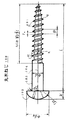
図4に示すJIS B−1112−1995に規格される木ねじのように、頭部とこの下にフラット部とねじ山を長手方向に備えるねじ材は、木工家具の製造、携帯電話、音響製品、電化製品、通信機器等に利用されている。この規格によると木ねじのねじ山の角度は通常45〜55度、ねじ部には適当なテ−パ−を付け、ねじの谷の径と外径との比は、ねじ部のほぼ中央部において0.65〜0.75とし、ねじ山は最先端までなければならないと規定している。
ねじ材の軸線104に対するねじ山のピッチ角度θは、図4では約78度となっている。市販されているねじ材には、ねじ山のピッチ角度が78度とは異なった木ねじもあれば、ねじ山が最先端まではないリ−マ付きドリルねじ、タッピンねじ、止めねじもある。また、頭部の形状も丸状であったり、皿状であったりする。さらに、フラット部が無いねじ材もある。
【0003】
従来、頭部とねじ部を備えるねじ材の製造方法としては、鋼線、銅線、ステンレス線のような金属線材を適切な長さに切断し、圧造金型で線材の端に頭部とフラット部を成形するヘッダ工程と、ついで、頭部が形成された線材の脚部を固定ロ−リングダイと移動ロ−リングダイ間に転がして線材に雄ねじ山を多数形成させるロ−リング(転造)工程を経て製造される(例えば、特許文献1および特許文献2参照)。また、頭部を圧造し、ねじ部を転造した後、リ−マと先端ドリル部を圧造してねじ材を生産することも知られている(例えば、特許文献3参照)
【0004】
【特許文献1】
特開平7−259833号公報(第3欄41行から第5欄17行および図5、図6)。
【特許文献2】
特開2001−9638号公報(第2頁段落0001から段落0004の記載および図5、図6)。
【特許文献3】
特開平10−314882号公報(第4頁段落0013から0015の記載および図1、図6)。
【0005】
【発明が解決しようとする課題】
携帯電話、移動端末の小型化に連れてねじ材も小さく、強度が大きく、寸法制度の精密なものが市場から望まれている。
しかしながら、従来のねじ材のねじ部は転造(ロ−リング)で製造されており、締付強度および寸法精度の向上が望まれている。ドリル刃を用いて圧造金型部材を切削加工することも考えられるが、表面平坦性が悪く、寸法精度が出ない。
【0006】
本発明は、切削加工よりは平坦性がよい研削加工によりワ−クにねじ用溝を加工することができる研削装置の提供および、ねじ部を圧造で生産できる圧造金型の提供を目的とする。
【0007】
【課題を解決するための手段】
請求項1の発明は、ねじ状溝を研削する砥石車を回転自在に軸承する砥石軸、該砥石軸を垂直方向(Y軸方向)に昇降する昇降機構、左右方向(X軸方向)に移動可能なテ−ブル、該テ−ブル上に取り付けられたスイベルのロ−タリ−テ−ブル上に左右方向(V軸方向)に旋回可能に取り付けられた第1スイベル機構と、該第1スイベル機構上に前後方向(V軸方向)に旋回可能に取り付けられた第2スイベル機構、該第2スイベル機構上に固定された電磁チャックとを備える金型部材にねじ状溝を成形する研削装置を提供するものである。
【0008】
砥石車による溝の研削加工であるので、切削加工よりは寸法精度のよいねじ溝を形成できる。ロ−タリ−テ−ブルの回転により加工される金型部材(ワ−ク)をねじ山のピッチ角度θに適した位置に移動できる。第1スイベル機構1と第2スイベル機構の動きを同期させることによりワ−クがねじ山のピッチP分移動する間にねじ部頂上部に適当なテ−パ−を形成することができる。
【0009】
請求項2の発明は、ねじ状溝を研削した金型部材の複数を、ねじ部材の軸線方向に対してその両側面を切り取り断面90度角のセグメント4個または切り取り断面60度角のセグメント6個または切り取り断面45度角のセグメント8個のねじ状溝形成金型部材を製造し、ついでこの4セグメントまたは6セグメントまたは8セグメントのねじ状溝形成金型部材をねじ材の軸線方向に少しづつづらして面合わせしてセグメントが形成したブロック内部に螺旋状の雌ねじ溝を有するねじ部のキャビティを形成した後、このブロックをねじ材の軸線方向に対して垂直に切断し、これら切断されたブロックのセグメント2個づつまたは3個づつまたは4個づつを固定金型母材と移動金型母材内にねじ頭成形金型部材とともに挿入して固定金型と移動金型を調製し、この両金型で線材を圧造してねじ材のねじ部を形成することを可能としたねじ材圧造用成形金型を提供するものである。
【0010】
一対の固定金型と移動金型間に線材を挟み、圧造(冷間鍛造)することによりねじ材のねじ部、金型によっては、頭部、フラット部、リ−マ部を製造できる。固定金型と移動金型は金型母材を面合わせするので、挿入された入れ子のセグメントはセグメントが2個または3個または4個組み合わされた際、雌ねじ状溝の形成された内面側の型合わせ面が180度の平面を成す。
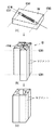
ねじ材のねじ山は螺旋状であるので、各セグメントを組み合わせてブロック化した雌ねじ状溝が連続した螺旋状となるように各セグメントを少しづつづらして面合わせし、ついでこのブロックをねじ部材の軸線方向に対して垂直に切断して入れ子を製造する。
【0011】
【発明の実施の形態】
【実施例】
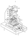
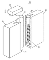
以下、図面を用いて本発明を更に詳細に説明する。図1は本発明のねじ状溝研削装置の斜視図、図2は圧造金型の斜視図、図3はねじ部形成圧造金型の組み立て工程を示す説明図、および図4はJIS B−1112−1995に示される丸木ねじの正面図である。
【0012】
図4に示されるJIS B−1112−1995の丸木ねじ100において、101はねじ山(ねじ山の条数nは12個)、102は頭部、103はフラット部、104は丸木ねじの中心軸線(長手方向軸)、Pはピッチ幅、Pwはねじ山間の谷部の長さ、Kは頭部厚さ、lはフラット部とねじ部を合わせた長さ、Qはねじ山のテ−パ−部、Hは丸木ねじの中心線からねじ山頂部までの垂直高さ、hは丸木ねじの軸線からねじ山のテ−パ−が始まる位置(谷部)までの垂直高さを示す。JIS B1112−1995規格ではねじ材の谷の径と外径との比は、ねじ部のほぼ中央部において0.65〜0.75と規定している。
【0013】
図1に示すねじ状溝研削装置1において、2はベ−ス、3は左右方向(X軸方向)に移動可能なテ−ブル、4はガイドレ−ル、5はボ−ルネジ、6はサ−ボモ−タである。
テ−ブル3下面には、螺合体5aが固定され、サ−ボモ−タ6の駆動回転力を受けて回動するボ−ルネジ5の駆動力を受けて左右に移動できる。
【0014】
7はスイベル、8は基台、9はθステ−ジ機構、10はロ−タリ−テ−ブル、11は第1スイベル機構、12は第2スイベル機構、13は電磁チャック、wはワ−クである金型部材、14は微動クランプ、15はマイクロメ−タヘッド、15aは突出片15aである。
【0015】
スイベル7は、被加工物のワ−クを固定する電磁チャック13を水平方向、垂直方向に旋回可能に取り付ける保持具である。基台8上に設けられたθステ−ジ機構9はロ−タリ−テ−ブル10を中心点を軸に水平方向(R)に旋回可能とするもので、微動クランプ14と、マイクロメ−タヘッド15と、突出片15aと旋回角度目盛と、微動クランプ14が備えられている反対側に備えられた図示されていない粗動クランプを備える。
粗動クランプを緩めると、ロ−タリ−テ−ブル10は基台8に対して自由に旋回可能となるので、粗動クランプを緩め、ロ−タリ−テ−ブルを目標位置(ねじ山のピッチ角度θ)の近傍に旋回し、しかる後、粗動クランプを締結する。
突出片15aは、クランプ14とマイクロメ−タヘッド15に挟み込まれており、マイクロメ−タヘッド15を回すことによりロ−タリ−テ−ブルの接線方向に押されてわずかに旋回し、ロ−タリ−テ−ブル10の旋回角度位置を正確に調整できる。
【0016】
第1スイベル機構11および第2スイベル機構12は、それぞれ垂直方向に旋回可能な旋回ステ−ジ11a,12aと、この旋回ステ−ジを旋回可能に支持する支持台11b,12bと、旋回ステ−ジを支持台側に固定するクランプ11c,12cと、旋回ステ−ジの旋回位置を調整するための図示されていないハンドルを備える。
【0017】
第1スイベル機構11および第2スイベル機構12の支持台11b,12bは、θステ−ジ機構9のロ−タリ−テ−ブル10の上に取り付け固定されている。第1スイベル機構11および第2スイベル機構12の旋回ステ−ジ11a,12aは、θステ−ジ機構9のロ−タリ−テ−ブル10の旋回中心軸線(垂線)とは直交する旋回中心軸線(水平線)の回りに旋回可能となっている。第1スイベル機構11および第2スイベル機構12の旋回ステ−ジ11a,12aを旋回させるとそれぞれの旋回ステ−ジが上下方向に旋回するので、電磁チャックに固定されている金型部材wの傾斜角度を調製できる。すなわち、図1において、V軸方向に平行にワ−クwのねじ材の長手方向軸線104が存在するようにワ−クが置かれると、第1スイベル機構はねじ山のテ−パ−角度を調整し、第2スイベル機構はねじ材の長手方向軸線104に対し垂直面の研削されるワ−ク角度を調整する。
【0018】
具体的には、ねじ山のテ−パ−角度が45度のとき、第1スイベル機構は0度を中心に+22.5度と−22.5度の間の45度を往復旋回する。すなわち、0度から22.5度旋回した後、逆方向に旋回を始め、0度を経て−22.5度まで旋回し、そこから再び、+22.5度まで逆方向に旋回し、以下、この旋回揺動を繰返す。研削終了点では、0度まで戻し、ついで砥石車を上昇させる。
第2スイベル機構は、研削される金型部材8個で1個のねじ材のキャビティを形成するときは、第2スイベル機構は0度を中心に+22.5度と−22.5度の間の45度を往復旋回する。すなわち、0度から22.5度旋回した後、逆方向に旋回を始め、0度を経て−22.5度まで旋回し、そこから再び、+22.5度まで逆方向に旋回し、以下、この旋回揺動を繰返す。
金型部材6個で1個のねじ材ぼキャビティを形成するときは、0度を中心に+30度と−30度の間の60度を往復旋回する。すなわち、0度から+30度旋回した後、逆方向に旋回を始め、0度を経て−30度まで旋回し、そこから再び、+30度まで逆方向に旋回し、以下、この旋回揺動を繰返す。
金型部材4個で1個のねじ材ぼキャビティを形成するときは、0度を中心に+45度と−45度の間の90度を往復旋回する。すなわち、0度から+45度旋回した後、逆方向に旋回を始め、0度を経て−45度まで旋回し、そこから再び、+45度まで逆方向に旋回し、以下、この旋回揺動を繰返す。
研削終了点では、0度まで戻し、ついで砥石車を上昇させる。
【0019】
基台8、θステ−ジ機構9および1個のスイベル機構11を備えたスイベルは、栄精密工業株式会社、株式会社三協精機製作所などから入手できるので、このスイベルの第1スイベル機構11上に更に第2スイベル機構12と電磁チャック13を載せて図1に示すスイベル7を完成させる。第1スイベル機構11の旋回ステ−ジ11aおよび第2スイベル機構12の旋回ステ−ジ12aが直交するように載せ、第1スイベル機構11の旋回ステ−ジ11aおよび第2スイベル機構12の旋回ステ−ジ12aの動きが同期するよう図示されていないウヲ−ム歯車を歯車ボックス内で噛み合わせてある。
【0020】
図1において、16は砥石車、17はフランジで砥石軸に固定された砥石車を締め付ている。18は砥石軸頭で上下方向(Y軸方向)に昇降自在にスライド板19に固定されている。スライド板22は取り付け板20の表面に垂直方向に設けられた案内レ−ル21上を上下方向に移動できる。ボ−ルネジ23を介してサ−ボモ−タ22の駆動を受け、案内レ−ル21上を上下方向に移動できる。
図示されていない砥石軸はモ−タ24の回転駆動力を受け、砥石車16を回転させる。
【0021】
砥石車16としては、ダイヤモンド砥石、CBN砥石が、ワ−ク素材としてはタングステン・カ−ボン合金、タングステン・モリブテン合金、ステンレス鋼、ニッケル・クロム鋼が挙げられる。砥石車16の軸線方向厚さは、ねじ材の谷部の長さPwより薄い厚さ、例えば0.2Pw〜0.85Pwであり、かつ、(P−Pw)に近い厚みである。砥石車16の直径は30〜180mmで充分である。
【0022】
ねじ材のねじ部の入れ子(金型部材)を成形するには、図1に示す研削装置1を用い、先ず、電磁チャック13上に長尺状ワ−クwを載せて固定し、スイベル7のθステ−ジ機構9を利用してロ−タリ−テ−ブル10をねじ山のピッチ角θ回転させる。ピッチ角θが1〜45度のときはそのピッチ角θ分だけ旋回させる。ピッチ角θが45度を越え、90度未満の場合は、(90−θ)度分旋回させる。図4で示す丸木ねじではピッチ角θは78度であるので、12度分ロ−タリ−テ−ブル10を旋回する。
【0023】
この研削装置1では、固定金型、移動金型ともねじ部用の雌ねじ溝を金型部材に一度の研削加工で完成できるものではない。よって、作業者は、先ず、ねじ山のキャビティを形成するのに幾つ(n個)のセグメント(金型部材)を用いるか決める。例えば、断面90度角のセグメント4個、切り取り断面60度角のセグメント6個、あるいは45度角のセグメント8個の中から選択する。
【0024】
次に、作業者はねじ状溝形成金型部材ねじ山101の条数m、ピッチ幅P、ピッチ角度θ、ねじ山の谷部の幅Pw、ねじの中心線からねじ山頂部までの垂直高さH、丸木ねじの中心線からねじ山のテ−パ−が始まる位置(谷部)までの垂直高さh、ねじ材の谷の径と外径との比がねじ部のほぼ中央部において0.65〜0.75をよく記憶し、砥石車の昇降距離、左右テ−ブル3の送り、第1スイベル機構11と第2スイベル機構のスイベル角に注意して加工操作すべきである。
【0025】
作業者は、ねじ山のテ−パ−角度γは、
tan γ=tan 22.5=(P−Pw)/2(Hi−hi)
で近似できることに留意すべきである。なお、iはi番目のねじ山を示し、Hiはねじ材の軸線104からi番目のねじ山の頂部までの垂直高さを、hiはねじ材の軸線104からi番目のねじ山の谷部までの垂直高さを意味する。
【0026】
金型部材に雌溝(木ねじの谷部の幅Pwは2.5mm、ピッチ角78度、テ−パ−角45度)を加工する研削砥石車16として、直径が150mm、厚み1.0mm、先端が0.5Rの丸型平砥石を用い、セグメント数が8個の金型部材を加工する例を以って、1金型部材セグメントに溝加工する例を次に示す。
モ−タ24を駆動することで砥石基準点位置にある砥石車16を回転させ、次いで、モ−タ22を稼動して砥石車を下降させ、前記ねじ山のピッチ角θが78度に対応する角度12度(90−78=12)だけθステ−ジ機構9によりロ−タリ−テ−ブルを旋回させることにより旋回されたワ−クw表面(研削開始点)に触れさせ、そのまま砥石車を下降させつつ、ねじの中心線からねじ山のテ−パ−が始まる位置(谷部)までの垂直高さhiまでシフトプランジ研削を続行し、垂直高さhiの谷部に相当する溝をワ−クに加工する。
【0027】
ついで、第1スイベル機構の旋回を0度から+22.5度へ、ついで逆方向に−22.5度へとこの揺動旋回を繰り返えすとともに、第2スイベル機構の旋回を0度から+22.5度へ、ついで逆方向に−22.5度へとこの揺動旋回を繰り返えし、ねじ山に相当する深さHiの雌ねじ溝をワ−クに研削し、ついで、それぞれのスイベル機構の角度を0度に戻し、砥石車を上昇させてワ−クより遠ざける。この工程では、iが1番目のねじ山の(H1−h1)の深さの雌溝が研削される。
【0028】
ついで、サ−ボモ−タ6を駆動して左右テ−ブル3をねじ山のピッチP幅だけ右方向に移動させ、前記砥石車を下降させつつ、金型部材に接触させ、前記と同様にしてi=2のねじ山の溝加工を行う。
【0029】
以下、同様にしてi=m番目までの溝を研削したら砥石車を上昇させ、回転している砥石車をワ−クより遠ざける。m個のねじ山溝が金型部材wに研削されたら、金型部材wを電磁チャックより取り外す。
ねじ山溝に続いて深さd/2のフラット部103用溝をも金型部材に加工するときは、より幅広の別の砥石車と取り替え、ワ−クをピッチ幅だけ更に移動させ、角度12度(90−78=12)だけθステ−ジ機構9によりロ−タリ−テ−ブルを旋回させた後、砥石車を下降させ旋回されたワ−クw表面に触れさせ、そのまま砥石車を下降させつつ、d/2の長さまで下降させて溝研削を行い、ついで、砥石車を上昇させ、砥石幅よりは若干短くワ−クを右方向に移動させ、以下、砥石車を下降させつつ、d/2の長さまで下降させて溝研削を行い、ついで、砥石車を上昇させ、砥石幅よりは若干短くワ−クを右方向に移動させるシフトプランジ研削を行い、1/3lより若干幅広い半円柱状溝を加工する。
【0030】
このようにして、第1の金型部材セグメントに雌ねじ溝が成形されたら、以下同様にして所望の個数n=8個の金型部材セグメントに雌ねじ溝を、必要によりフラット部用溝を研削加工する。
【0031】
前記金型部材であるこれら分割セグメントwに雌ねじ溝加工した後、各々n個のセグメントを中心角が90度、60度、または45度となるよう旋盤を用いて切断加工(図3a)し、ついでこの4セグメントまたは6セグメントまたは8セグメントのねじ状溝形成金型部材をねじ材の軸線方向104に少しづつ、具体的には(P−Pw)/nづつづらして面合わせしてセグメントが形成したブロックB内部に螺旋状の雌ねじ溝を有するねじ部のキャビティ、必要によりフラット部のキャビテイを形成した後、このブロックをねじ材の軸線方向に対して垂直に切断し(図3b参照。図3ではセグメント数n=8個の例を示す)、これら切断されたブロックのセグメント2個づつまたは3個づつまたは4個づつを固定金型母材(型枠)34と移動金型母材(型枠)35内にねじ頭成形金型部材36とともに挿入して固定金型31と移動金型32を調製する。
【0032】
この両金型31,32で線材40を挟持して圧造することによりねじ材のねじ部を形成することが可能となる。
具体的には、図2に示す固定金型31、移動金型32および頭部成形金型33よりなる圧造金型30を用いて金属線材40より図4に示すねじ材100を製造するには、所望長さの金属線材40を固定金型31側に接触させ、ついで移動金型32を固定金型側に移動して型締めして金属線材40を固定金型31と移動金型32で圧造してねじ部、フラット部および頭部の一部を成形し、ついで上方より頭部成形金型33を下降させ、型締めしている固定金型31と移動金型32の頂部に圧接させ、ねじ材の頭部を完全な形へと鍛造する。
先にねじ材の頭部を圧造し、ついで、固定金型31と移動金型32で頭部が形成された線材を圧造してねじ山、フラット部を成形してもよい。
【0033】
【発明の効果】
本発明の金型部材にねじ状溝を成形する研削装置は、ねじ材圧造用成形金型のねじ山を形成する入れ子を研削加工することができ、この入れ子を挿入したねじ材圧造用成形金型を用いて、線材を圧造してねじ山を成形することができる。圧造で成形されたねじ山は、従来法の転造で成形されたねじ山より寸法精度、表面平滑度、機械強度が良好である。
【図面の簡単な説明】
【図1】本発明の金型部材にねじ状溝を成形する研削装置の斜視図である。
【図2】圧造金型の斜視図である。
【図3】金型部材セグメントより圧造金型を組み立てる工程を示す説明図である。
【図4】丸木ねじの正面図である。
【符号の簡単な説明】
1 研削装置
w ワ−ク
3 左右移動テ−ブル
7 スイベル
10 ロ−タリ−テ−ブル
11 第1スイベル機構
12 第2スイベル機構
13 電磁チャック
16 砥石車
30 圧造金型
31 固定金型
32 移動金型
33 頭部成形金型
100 ねじ材
101 ねじ山
102 頭部
103 フラット部
104 ねじ材の軸線[0001]
TECHNICAL FIELD OF THE INVENTION
The present invention relates to a grinding apparatus for grinding a thread-shaped groove in a nest of a forging die used for forming a thread material such as a wood screw by forging a wire rod, and a nest formed with the thread-shaped groove into a thread-forming metal. The present invention relates to a forming die for screw material forging inserted into a mold base material by combining a mold member with a nest for forging a screw head. .
[0002]
[Prior art]
Like a wood screw standardized in JIS B-1112-1995 shown in FIG. 4, a screw material having a head and a flat portion and a screw thread in a longitudinal direction under the head is used for manufacturing woodwork furniture, a mobile phone, an acoustic product, It is used for electrical appliances, communication equipment, etc. According to this standard, the angle of the screw thread of a wood screw is usually 45 to 55 degrees, an appropriate taper is attached to the screw part, and the ratio of the diameter of the screw root to the outer diameter is approximately at the center of the screw part. It is set to 0.65 to 0.75, and stipulates that the thread must be at the leading edge.
The pitch angle θ of the screw thread with respect to the axis 104 of the screw material is about 78 degrees in FIG. Some commercially available threaded materials include wood screws having a pitch angle of the thread different from 78 degrees, and also include reamed drill screws, tapping screws, and set screws in which the thread is not at the forefront. Also, the head has a round shape or a dish shape. Furthermore, there is a screw material without a flat portion.
[0003]
Conventionally, as a method of manufacturing a screw material having a head and a screw portion, a metal wire such as a steel wire, a copper wire, or a stainless steel wire is cut into an appropriate length, and a head is formed at an end of the wire with a forging die. A header step of forming a flat portion, and then rolling the legs of the wire having the head formed between the fixed rolling die and the moving rolling die to form a large number of external threads on the wire. (Patent Document 1 and Patent Document 2). It is also known to produce a threaded material by forging a head and rolling a screw portion, and then forging a reamer and a tip drill portion (for example, see Patent Document 3).
[0004]
[Patent Document 1]
JP-A-7-259833 (column 3, line 41 to column 5, line 17 and FIGS. 5, 6).
[Patent Document 2]
JP-A-2001-9638 (page 2, paragraphs 0001 to 0004 and FIGS. 5 and 6).
[Patent Document 3]
JP-A-10-314882 (p.4, paragraphs 0013 to 0015 and FIGS. 1, 6).
[0005]
[Problems to be solved by the invention]
With the miniaturization of mobile phones and mobile terminals, smaller screws, higher strength, and precise dimensional accuracy have been demanded from the market.
However, the threaded portion of the conventional threaded material is manufactured by rolling, and it is desired to improve the tightening strength and the dimensional accuracy. It is also conceivable to cut the forging die member using a drill blade, but the surface flatness is poor and dimensional accuracy cannot be obtained.
[0006]
SUMMARY OF THE INVENTION It is an object of the present invention to provide a grinding apparatus capable of forming a thread groove on a work by grinding processing having better flatness than cutting processing, and providing a forging die capable of producing a thread portion by forging. .
[0007]
[Means for Solving the Problems]
According to the first aspect of the present invention, a grinding wheel shaft rotatably supports a grinding wheel for grinding a thread groove, a lifting mechanism for vertically moving the grinding wheel shaft (Y-axis direction), and moving in the left-right direction (X-axis direction). A possible swivel, a first swivel mechanism mounted on the rotary table of a swivel mounted on the table so as to be pivotable in the left-right direction (V-axis direction), and the first swivel A grinding device for forming a thread-like groove in a mold member including a second swivel mechanism rotatably mounted on the mechanism in a front-rear direction (V-axis direction) and an electromagnetic chuck fixed on the second swivel mechanism. To provide.
[0008]
Since the grooves are ground by a grinding wheel, thread grooves having higher dimensional accuracy than cutting can be formed. The die member (work) processed by the rotation of the rotary table can be moved to a position suitable for the pitch angle θ of the thread. By synchronizing the movements of the first swivel mechanism 1 and the second swivel mechanism, an appropriate taper can be formed on the top of the thread while the work moves by the pitch P of the thread.
[0009]
According to a second aspect of the present invention, a plurality of the die members each having the thread-shaped groove ground, four segments each having a cut-away cross section of 90 degrees or a segment 6 each having a cut cross-section of 60 degrees are obtained by cutting both side surfaces of the screw member in the axial direction. A threaded groove forming die member having eight pieces or eight segments each having a cut-off cross section of 45 degrees is manufactured, and then the four-segment, six-segment or eight-segment thread-forming grooved member is gradually moved in the axial direction of the screw material. After forming a threaded cavity having a helical female screw groove inside the block where the segments are formed by face-to-face matching, the block is cut perpendicularly to the axial direction of the threaded material, and the cut block is cut. Insert two or three or four segments of the above together with the screw head forming die member into the fixed die base material and moving die base material and move with the fixed die. Type was prepared, and provides the possibility and the screw member heading for the molding die to form a threaded portion of the screw member by forging a wire rod in the molds.
[0010]
A head, a flat part, and a reamer part can be manufactured depending on a screw part of a screw material and a die by sandwiching a wire between a pair of fixed molds and a movable mold and performing forging (cold forging). Since the fixed mold and the movable mold face the mold base material, the inserted nested segment is formed when the two, three, or four segments are combined with each other on the inner surface side where the female screw groove is formed. The mating surface forms a 180-degree plane.
Since the thread of the screw material is helical, the segments are slightly squeezed so that the female screw grooves formed by combining the segments into a continuous helical shape are surface-matched. The nest is manufactured by cutting perpendicular to the axial direction.
[0011]
BEST MODE FOR CARRYING OUT THE INVENTION
【Example】
Hereinafter, the present invention will be described in more detail with reference to the drawings. FIG. 1 is a perspective view of the thread groove grinder of the present invention, FIG. 2 is a perspective view of a forging die, FIG. 3 is an explanatory view showing an assembling process of a threaded forming die, and FIG. 4 is JIS B-1112. FIG. 19 is a front view of the log screw shown in FIG.
[0012]
In the log wood screw 100 of JIS B-1112-1995 shown in FIG. 4, 101 is a thread (the number of threads n is 12), 102 is a head, 103 is a flat part, and 104 is a central axis of a round wood screw. (longitudinal axis), P is a pitch width, P w is the threads of the valley length of, K is the head thickness, l is the combined length of the flat portion and the threaded portion, Q is the thread of Te - The par portion, H, indicates the vertical height from the center line of the log screw to the top of the screw, and h indicates the vertical height from the axis of the log screw to the position where the taper of the screw starts (valley). According to the JIS B1112-1995 standard, the ratio between the diameter of the root of the threaded material and the outer diameter is specified to be 0.65 to 0.75 at the approximate center of the threaded portion.
[0013]
In the threaded groove grinding apparatus 1 shown in FIG. 1, 2 is a base, 3 is a table movable in the left-right direction (X-axis direction), 4 is a guide rail, 5 is a ball screw, and 6 is a support. -Vomotor.
A screw body 5a is fixed to the lower surface of the table 3, and can move left and right by receiving the driving force of the ball screw 5 which rotates by receiving the driving torque of the servo motor 6.
[0014]
7 is a swivel, 8 is a base, 9 is a θ stage mechanism, 10 is a rotary table, 11 is a first swivel mechanism, 12 is a second swivel mechanism, 13 is an electromagnetic chuck, and w is a wire. A mold member 14 is a fine movement clamp, 15 is a micrometer head, and 15a is a protruding piece 15a.
[0015]
The swivel 7 is a holder for attaching an electromagnetic chuck 13 for fixing a work of a workpiece so as to be able to turn horizontally and vertically. The .theta. Stage mechanism 9 provided on the base 8 allows the rotary table 10 to turn in the horizontal direction (R) about the center point as an axis. The fine movement clamp 14 and the micrometer head 15, a protruding piece 15 a, a turning angle scale, and a coarse movement clamp (not shown) provided on the opposite side where the fine movement clamp 14 is provided.
When the coarse clamp is loosened, the rotary table 10 can freely rotate with respect to the base 8. Therefore, the coarse clamp is loosened, and the rotary table is moved to the target position (thread position). (The pitch angle θ), and then the coarse clamp is fastened.
The protruding piece 15a is sandwiched between the clamp 14 and the micrometer head 15. When the micrometer head 15 is turned, the protruding piece 15a is pushed in the tangential direction of the rotary table and slightly turns to rotate the rotary table. -The turning angle position of the bull 10 can be adjusted accurately.
[0016]
The first swivel mechanism 11 and the second swivel mechanism 12 are respectively provided with turning stages 11a and 12a that can turn in the vertical direction, support tables 11b and 12b that support the turning stages in a turnable manner, and a turning stage. It has clamps 11c and 12c for fixing the stage to the support base side, and a handle (not shown) for adjusting the turning position of the turning stage.
[0017]
The support bases 11b and 12b of the first swivel mechanism 11 and the second swivel mechanism 12 are mounted and fixed on a rotary table 10 of the θ stage mechanism 9. The turning stages 11a and 12a of the first swivel mechanism 11 and the second swivel mechanism 12 have a turning center axis perpendicular to the turning center axis (perpendicular) of the rotary table 10 of the θ stage mechanism 9. (Horizontal line). When the turning stages 11a, 12a of the first swivel mechanism 11 and the second swivel mechanism 12 are turned, the respective turning stages are turned up and down, so that the inclination of the mold member w fixed to the electromagnetic chuck is increased. Angle can be adjusted. That is, in FIG. 1, when the work is placed so that the longitudinal axis 104 of the threaded material of the work w is present in parallel with the V-axis direction, the first swivel mechanism operates the taper angle of the thread. And the second swivel mechanism adjusts the work angle at which the plane perpendicular to the longitudinal axis 104 of the thread is ground.
[0018]
Specifically, when the taper angle of the thread is 45 degrees, the first swivel mechanism reciprocates 45 degrees between +22.5 degrees and -22.5 degrees around 0 degree. That is, after turning from 0 degrees to 22.5 degrees, it starts turning in the opposite direction, turns through 0 degrees to -22.5 degrees, and then turns again to +22.5 degrees, and thereafter, This turning swing is repeated. At the grinding end point, the angle is returned to 0 degrees, and then the grinding wheel is raised.
When the second swivel mechanism forms a single threaded cavity with eight die members to be ground, the second swivel mechanism is between +22.5 degrees and -22.5 degrees centering on 0 degrees. 45 degrees reciprocating. That is, after turning from 0 degrees to 22.5 degrees, it starts turning in the opposite direction, turns through 0 degrees to -22.5 degrees, and then turns again to +22.5 degrees, and thereafter, This turning swing is repeated.
When one screw hole cavity is formed by six mold members, the screw member reciprocates 60 degrees between +30 degrees and -30 degrees around 0 degree. That is, after turning from 0 degrees to +30 degrees, the turning starts in the opposite direction, turns through 0 degrees to -30 degrees, turns again from +30 degrees to +30 degrees, and thereafter repeats the turning swing. .
When one screw hole cavity is formed by four mold members, the screw member is reciprocated by 90 degrees between +45 degrees and -45 degrees around 0 degree. That is, after turning from 0 degree to +45 degree, it starts to turn in the reverse direction, turns through 0 degree to -45 degree, then turns again to +45 degree in the reverse direction, and thereafter repeats this turning swing. .
At the grinding end point, the angle is returned to 0 degrees, and then the grinding wheel is raised.
[0019]
A swivel provided with the base 8, the .theta. Stage mechanism 9, and one swivel mechanism 11 can be obtained from Sakae Seimitsu Kogyo Co., Ltd., Sankyo Seiki Seisakusho Co., Ltd., or the like. Then, the second swivel mechanism 12 and the electromagnetic chuck 13 are further mounted thereon to complete the swivel 7 shown in FIG. The turning stage 11a of the first swivel mechanism 11 and the turning stage 12a of the second swivel mechanism 12 are mounted so as to be orthogonal to each other, and the turning stage 11a of the first swivel mechanism 11 and the turning stage of the second swivel mechanism 12 are mounted. A worm gear (not shown) is meshed in the gear box so that the movement of the jaws 12a is synchronized.
[0020]
In FIG. 1, reference numeral 16 denotes a grinding wheel, and 17 denotes a flange which fastens a grinding wheel fixed to a grinding wheel shaft. Reference numeral 18 denotes a grindstone shaft head, which is fixed to a slide plate 19 so as to be vertically movable (Y-axis direction). The slide plate 22 can move up and down on a guide rail 21 provided vertically on the surface of the mounting plate 20. The drive of the servo motor 22 through the ball screw 23 allows the guide rail 21 to move up and down.
A grinding wheel shaft (not shown) receives the rotational driving force of the motor 24 and rotates the grinding wheel 16.
[0021]
Examples of the grinding wheel 16 include a diamond grinding wheel and a CBN grinding wheel, and examples of the work material include a tungsten-carbon alloy, a tungsten-molybdenum alloy, stainless steel, and nickel-chrome steel. Axial thickness of the wheel 16, valley length P w thinner than the thickness of the screw member, for example, 0.2P w ~0.85P w, and a thickness close to the (P-P w) is there. A diameter of the grinding wheel 16 of 30 to 180 mm is sufficient.
[0022]
In order to form the nest (die member) of the threaded portion of the threaded material, the grinding device 1 shown in FIG. The rotary table 10 is rotated by the pitch angle .theta. Of the thread using the .theta. When the pitch angle θ is 1 to 45 degrees, the vehicle is turned by the pitch angle θ. When the pitch angle θ exceeds 45 degrees and is less than 90 degrees, the vehicle is turned by (90−θ) degrees. 4, the pitch angle θ is 78 degrees, so that the rotary table 10 is turned by 12 degrees.
[0023]
In this grinding apparatus 1, both the fixed mold and the movable mold cannot complete the female thread groove for the screw portion on the mold member by a single grinding process. Therefore, the operator first determines how many (n) segments (mold members) are to be used to form the thread cavity. For example, it is selected from four segments having a 90-degree angle cross section, six segments having a 60-degree angle cut section, or eight segments having a 45-degree angle.
[0024]
Next, the operator can determine the number m of threads of the thread-shaped groove forming mold member thread 101, the pitch width P, the pitch angle θ, the width P w of the thread root, and the vertical direction from the center line of the screw to the thread peak. The height H, the vertical height h from the center line of the log screw to the position where the taper of the thread starts (trough), and the ratio of the diameter of the valley to the outer diameter of the thread material is approximately the center of the thread. In the above, 0.65 to 0.75 should be well stored, and the machining operation should be performed while paying attention to the vertical distance of the grinding wheel, the feed of the left and right tables 3, and the swivel angles of the first swivel mechanism 11 and the second swivel mechanism. .
[0025]
The worker has a taper angle γ of
tan γ = tan 22.5 = (P -P w) / 2 (H i -h i)
Note that can be approximated by Incidentally, i is shown an i-th thread, H i is the vertical height from the axis 104 of the screw member to the top of the i-th thread, h i is the i-th thread from the axis 104 of the screw member It means the vertical height to the valley.
[0026]
Female grooves in the mold member (the width P w of the valley of wood screws 2.5 mm, pitch angle 78 degrees, Te - Pa - angle 45 degrees) as the grinding wheel 16 for processing a, 150 mm in diameter, thickness 1.0mm Next, an example in which a groove is formed in one mold member segment by using a round flat grindstone having a tip of 0.5R and processing a mold member having eight segments will be described.
By driving the motor 24, the grinding wheel 16 at the grinding wheel reference point position is rotated, and then the motor 22 is operated to lower the grinding wheel, and the pitch angle θ of the thread corresponds to 78 degrees. The rotary table is rotated by the θ stage mechanism 9 by an angle of 12 degrees (90-78 = 12) to make contact with the surface of the work w which has been turned (grinding start point), and the grindstone as it is while lowering the car, from the center line of the screw thread Te - Pa - continue the shift plunge grinding until vertical height h i to begin position (valley), corresponding to the valleys of the vertical height h i The groove to be worked into a work.
[0027]
Then, the swing of the first swivel mechanism is repeated from 0 degree to +22.5 degrees, and then the swinging rotation is repeated to -22.5 degrees in the opposite direction, and the rotation of the second swivel mechanism is reduced from 0 degrees to +22 degrees. to .5 degrees, then the opposite direction to -22.5 degrees to Kaee repeated this swinging pivot, the female screw groove depth H i corresponding to the thread word - grinding the click, then the respective Return the angle of the swivel mechanism to 0 degrees, raise the grinding wheel and move it away from the work. In this step, the female groove having the depth of (H 1 -h 1 ) of the first screw thread is ground.
[0028]
Then, the servo motor 6 is driven to move the left and right tables 3 to the right by the pitch P of the thread, and the lowering of the grinding wheel makes contact with the mold member. Then, groove processing of the thread of i = 2 is performed.
[0029]
Thereafter, after grinding the groove up to the i = m-th groove in the same manner, the grinding wheel is raised, and the rotating grinding wheel is moved away from the work. After the m thread grooves are ground on the mold member w, the mold member w is removed from the electromagnetic chuck.
When processing the groove for the flat portion 103 having a depth of d / 2 following the thread groove on the mold member, replace the wheel with another wider wheel and move the work further by the pitch width to obtain an angle of 12 degrees. After rotating the rotary table by the .theta. Stage mechanism 9 by the degree (90-78 = 12), the grinding wheel is lowered and brought into contact with the surface of the work w which has been rotated, and the grinding wheel is directly used. While lowering, the groove grinding is performed by descending to the length of d / 2, then the grinding wheel is raised, and the work is moved to the right slightly shorter than the width of the grinding wheel. , D / 2, to perform groove grinding, then raise the grinding wheel, perform shift plunge grinding to move the work to the right slightly shorter than the width of the grinding wheel, and slightly wider than 1/3 l Process a semi-cylindrical groove.
[0030]
After the female screw groove is formed in the first mold member segment in this manner, the female screw groove is formed in the desired number n = 8 of the mold member segments, and the flat portion groove is ground if necessary. I do.
[0031]
After the female segments are formed in the divided segments w which are the mold members, each of the n segments is cut using a lathe so that the central angle becomes 90 degrees, 60 degrees, or 45 degrees (FIG. 3A), Then, the four-segment, six-segment, or eight-segment thread-forming groove-forming mold members are gradually faced to each other in the axial direction 104 of the threaded material, specifically, by (P−P w ) / n, and the segments are aligned. After forming a cavity of a screw portion having a helical female screw groove inside the formed block B and, if necessary, a cavity of a flat portion, the block is cut perpendicularly to the axial direction of the screw material (see FIG. 3B. 3 shows an example in which the number of segments is n = 8), and every two, three, or four segments of these cut blocks are transferred to a fixed mold base material (mold frame) 34. The mold base material (mold) 35 is inserted together with the screw head forming die member 36 to prepare the fixed mold 31 and movable mold 32.
[0032]
The threaded portion of the threaded material can be formed by sandwiching the wire 40 between the two dies 31 and 32 and forging.
Specifically, to manufacture the screw member 100 shown in FIG. 4 from the metal wire 40 using the forging die 30 including the fixed die 31, the movable die 32, and the head forming die 33 shown in FIG. Then, the metal wire 40 having a desired length is brought into contact with the fixed mold 31 side, and then the movable mold 32 is moved to the fixed mold side and clamped to fix the metal wire 40 with the fixed mold 31 and the movable mold 32. The screw portion, the flat portion, and a part of the head portion are formed by forging, and then the head forming die 33 is lowered from above, and pressed against the fixed die 31 and the top of the movable die 32 which are being clamped. , Forging the head of the screw material to a perfect shape.
The head of the screw member may be forged first, and then the wire having the head formed by the fixed mold 31 and the movable mold 32 may be forged to form a screw thread and a flat portion.
[0033]
【The invention's effect】
The grinding apparatus for forming a thread-like groove in a mold member of the present invention can grind a nest forming a thread of a molding die for screw material forging, and form a molding die for screw material with the inserted nest. The thread can be formed by forging the wire using a mold. Threads formed by forging have better dimensional accuracy, surface smoothness, and mechanical strength than threads formed by conventional rolling.
[Brief description of the drawings]
FIG. 1 is a perspective view of a grinding device for forming a thread groove in a mold member of the present invention.
FIG. 2 is a perspective view of a forging die.
FIG. 3 is an explanatory view showing a step of assembling a forging die from a die member segment.
FIG. 4 is a front view of a log screw.
[Brief description of reference numerals]
DESCRIPTION OF SYMBOLS 1 Grinding device w Work 3 Left and right moving table 7 Swivel 10 Rotary table 11 First swivel mechanism 12 Second swivel mechanism 13 Electromagnetic chuck 16 Grinding wheel 30 Press forming die 31 Fixed die 32 Moving die Mold 33 Head forming die 100 Screw material 101 Thread 102 Head 103 Flat part 104 Axis of screw material