JP2004233040A - Superheated steam generator - Google Patents
Superheated steam generator Download PDFInfo
- Publication number
- JP2004233040A JP2004233040A JP2004022189A JP2004022189A JP2004233040A JP 2004233040 A JP2004233040 A JP 2004233040A JP 2004022189 A JP2004022189 A JP 2004022189A JP 2004022189 A JP2004022189 A JP 2004022189A JP 2004233040 A JP2004233040 A JP 2004233040A
- Authority
- JP
- Japan
- Prior art keywords
- superheated steam
- cylindrical body
- loaded
- conductive material
- water
- Prior art date
- Legal status (The legal status is an assumption and is not a legal conclusion. Google has not performed a legal analysis and makes no representation as to the accuracy of the status listed.)
- Pending
Links
Images

Classifications
-
- H—ELECTRICITY
- H05—ELECTRIC TECHNIQUES NOT OTHERWISE PROVIDED FOR
- H05B—ELECTRIC HEATING; ELECTRIC LIGHT SOURCES NOT OTHERWISE PROVIDED FOR; CIRCUIT ARRANGEMENTS FOR ELECTRIC LIGHT SOURCES, IN GENERAL
- H05B6/00—Heating by electric, magnetic or electromagnetic fields
- H05B6/02—Induction heating
- H05B6/10—Induction heating apparatus, other than furnaces, for specific applications
- H05B6/105—Induction heating apparatus, other than furnaces, for specific applications using a susceptor
- H05B6/108—Induction heating apparatus, other than furnaces, for specific applications using a susceptor for heating a fluid
-
- B—PERFORMING OPERATIONS; TRANSPORTING
- B24—GRINDING; POLISHING
- B24B—MACHINES, DEVICES, OR PROCESSES FOR GRINDING OR POLISHING; DRESSING OR CONDITIONING OF ABRADING SURFACES; FEEDING OF GRINDING, POLISHING, OR LAPPING AGENTS
- B24B49/00—Measuring or gauging equipment for controlling the feed movement of the grinding tool or work; Arrangements of indicating or measuring equipment, e.g. for indicating the start of the grinding operation
- B24B49/10—Measuring or gauging equipment for controlling the feed movement of the grinding tool or work; Arrangements of indicating or measuring equipment, e.g. for indicating the start of the grinding operation involving electrical means
- B24B49/105—Measuring or gauging equipment for controlling the feed movement of the grinding tool or work; Arrangements of indicating or measuring equipment, e.g. for indicating the start of the grinding operation involving electrical means using eddy currents
-
- F—MECHANICAL ENGINEERING; LIGHTING; HEATING; WEAPONS; BLASTING
- F22—STEAM GENERATION
- F22B—METHODS OF STEAM GENERATION; STEAM BOILERS
- F22B1/00—Methods of steam generation characterised by form of heating method
- F22B1/28—Methods of steam generation characterised by form of heating method in boilers heated electrically
- F22B1/281—Methods of steam generation characterised by form of heating method in boilers heated electrically other than by electrical resistances or electrodes
-
- F—MECHANICAL ENGINEERING; LIGHTING; HEATING; WEAPONS; BLASTING
- F22—STEAM GENERATION
- F22B—METHODS OF STEAM GENERATION; STEAM BOILERS
- F22B1/00—Methods of steam generation characterised by form of heating method
- F22B1/28—Methods of steam generation characterised by form of heating method in boilers heated electrically
- F22B1/287—Methods of steam generation characterised by form of heating method in boilers heated electrically with water in sprays or in films
Abstract
Description
本発明は、過熱水蒸気の生成技術に関し、特に大量の過熱水蒸気を容易に生成させる技術の提供に関する。 The present invention relates to a technique for generating superheated steam, and more particularly to a technique for easily generating a large amount of superheated steam.
過熱水蒸気は有害成分を含まない高温蒸気であるため食品の殺菌・滅菌用等に好適に用いられている。
過熱水蒸気を発生させる技術としては、例えば特開平8−135903号公報に開示されるものがあり、コイルに交流電流を流して金属体を電磁誘導で発熱させ、水蒸気をその発熱体表面に接触流通させることで100℃以上の水蒸気(過熱水蒸気)を発生、その他の技術としては例えば特開平9−241734号公報に示されるごとく、蒸気ボイラーで水を蒸発させ、さらにその蒸発した水蒸気を燃料の燃焼で高温に加熱するものである。
Superheated steam is a high-temperature steam containing no harmful components, and is suitably used for sterilizing and sterilizing foods.
As a technique for generating superheated steam, for example, there is a technique disclosed in Japanese Patent Application Laid-Open No. Hei 8-135903, in which an alternating current is applied to a coil to cause a metal body to generate heat by electromagnetic induction, and the steam is flowed in contact with the surface of the heating element. As a result, water is evaporated by a steam boiler, and the evaporated steam is burned as fuel, as shown in Japanese Patent Application Laid-Open No. 9-241732. To heat to a high temperature.
しかしながら、従来の電磁誘導加熱の技術では、高温の過熱水蒸気を大量に生成させることが容易でなく、また高圧の過熱水蒸気を生成させることも難しかった。 However, in the conventional electromagnetic induction heating technique, it is not easy to generate a large amount of high-temperature superheated steam, and it is also difficult to generate high-pressure superheated steam.
本願発明は前記従来の技術の課題を解決するもので、下記構成の過熱水蒸気生成装置及び高圧の過熱水蒸気を生成させる方法である。
(1) 一方端に噴射水の導入孔を備え、他方端に過熱水蒸気の噴出口を備えた非磁性体材料製の筒状体と、同筒状体の外周に巻回された励磁コイルと、同筒状体内に装填された導電体材料製の通気性被加熱体とを具備してなることを特徴とする過熱水蒸気生成装置。
(2)一方端に噴射水の導入孔と水蒸気の導入孔を備え、他方端に過熱水蒸気の噴出口を備えた非磁性体材料製の筒状体と、同筒状体の外周に巻回された励磁コイルと、同筒状体内に装填された導電体材料製の通気性被加熱体とを具備してなることを特徴とする過熱水蒸気生成装置。
The present invention solves the above-mentioned problems of the prior art, and is a superheated steam generator and a method of generating high-pressure superheated steam having the following configurations.
(1) A cylindrical body made of a non-magnetic material having an injection hole at one end and a jet port of superheated steam at the other end, and an exciting coil wound around the outer periphery of the cylindrical body. A superheated steam generating apparatus, comprising: a gas-permeable, heated body made of a conductive material loaded in the cylindrical body.
(2) A cylindrical body made of a non-magnetic material having an injection hole for injection water and an introduction hole for water vapor at one end and an injection port for superheated steam at the other end, and wound around the outer periphery of the cylindrical body A superheated steam generator, comprising: an excitation coil provided therein; and an air-permeable heated body made of a conductive material loaded in the cylindrical body.
(3)一方端から噴射水が導入され、他方端から過熱水蒸気が噴出される非磁性体材料製の筒状体と、同筒状体内に装填された噴射水を加熱するための電磁誘導で発熱する導電体材料製の通気性発熱体を備えた電磁誘導加熱手段とを具備してなることを特徴とする過熱水蒸気生成装置。
(4) 一方端に噴射水の導入孔を備え、他方端に過熱水蒸気の噴出口を備えた導電体材料製の筒状体と、同筒状体の外周面に被覆された非磁性体材料製の耐火材と、同耐火材の外周に巻回された励磁コイルと、同筒状体内に装填された導電体材料製の通気性被加熱体とを具備してなることを特徴とする過熱水蒸気生成装置。
(5)非磁性体材料がセラミックスであり、導電体材料が金属であることを特徴とする前記(1)〜(4)のいずれか1項に記載の過熱水蒸気生成装置。
(6)筒状体の一方端に水以外の液体の噴射液体の導入孔を備えてなることを特徴とする前記(1)〜(5)のいずれか1項に記載の過熱水蒸気生成装置。
(3) A cylindrical body made of a non-magnetic material, into which the jet water is introduced from one end and the superheated steam is jetted from the other end, and electromagnetic induction for heating the jet water loaded in the cylindrical body. A superheated steam generator comprising: an electromagnetic induction heating means having a gas-permeable heat-generating body made of a conductive material that generates heat.
(4) A tubular body made of a conductive material having an injection hole for injection water at one end and a jet port of superheated steam at the other end, and a non-magnetic material coated on the outer peripheral surface of the tubular body Overheating characterized by comprising a refractory material made of stainless steel, an exciting coil wound around the outer periphery of the refractory material, and a permeable heated body made of a conductive material loaded in the cylindrical body. Steam generator.
(5) The superheated steam generator according to any one of (1) to (4), wherein the non-magnetic material is ceramics and the conductive material is metal.
(6) The superheated steam generator according to any one of (1) to (5), further including an injection hole for ejecting a liquid other than water at one end of the cylindrical body.
(7)筒状体の一方端に水と他の液体との噴射液の導入孔を備えてなることを特徴とする前記(1)〜(5)のいずれか1項に記載の過熱水蒸気生成装置。
(8)筒状体の一方端に水蒸気と他の気体との導入孔を備えてなることを特徴とする前記(2)〜(7)のいずれか1項に記載の過熱水蒸気生成装置。
(9)水以外の液体又は気体が有機系塩素化合物を含むものであることを特徴とする前記(6)〜(8)のいずれか1項に記載の過熱水蒸気生成装置。
(10) 非磁性体材料製の筒状体の他方端の噴出口から噴出する過熱蒸気の温度が120〜800℃であることを特徴とする前記(1)〜(9)のいずれか1項に記載の過熱蒸気生成装置。
(7) The superheated steam generation according to any one of the above (1) to (5), wherein the cylindrical body is provided at one end with a hole for introducing a jet of water and another liquid. apparatus.
(8) The superheated steam generator according to any one of (2) to (7), further including an introduction hole for steam and another gas at one end of the cylindrical body.
(9) The superheated steam generator according to any one of the above (6) to (8), wherein the liquid or gas other than water contains an organic chlorine compound.
(10) The temperature of the superheated steam spouted from the spout at the other end of the cylindrical body made of a nonmagnetic material is 120 to 800 ° C, any one of the above (1) to (9). A superheated steam generator according to item 1.
(11)筒状体内に装填された導電体材料製の発熱体が、棒体、線材、板材、ハニカム材、網体、球体、中空球体又は不定形塊状体から選ばれる1種又は2種以上であることを特徴とする前記(1)〜(10)のいずれか1項に記載の過熱蒸気発生装置。
(12)筒状体内に装填された導電体材料製の発熱体が、磁性体であることを特徴とする前記(1)〜(11)のいずれか1項に記載の過熱蒸気発生装置。
(13) 導電体材料製の通気性被加熱体が装填された筒状体の一方端から筒内に水を噴射し、次いで同筒状体内に装填された前記通気性被加熱体を高周波誘導加熱することにより、筒状体の他方端から高温の過熱水蒸気を噴出せしめることを特徴とする高圧の過熱水蒸気を生成させる方法。
(14) 導電体材料製の通気性被加熱体が装填された筒状体の一方端から筒内に水と水蒸気を噴射し、次いで同筒状体内に装填された前記通気性被加熱体を高周波誘導加熱することにより、筒状体の他方端から高温の過熱水蒸気を噴出せしめることを特徴とする高圧の過熱水蒸気を生成させる方法。
(11) The heating element made of a conductive material loaded in the cylindrical body is at least one selected from a rod, a wire, a plate, a honeycomb, a net, a sphere, a hollow sphere, and an irregular mass. The superheated steam generator according to any one of the above (1) to (10), wherein
(12) The superheated steam generator according to any one of (1) to (11), wherein the heating element made of a conductive material loaded in the cylindrical body is a magnetic substance.
(13) Water is injected into the cylinder from one end of the cylindrical body loaded with the air-permeable heated body made of a conductive material, and then the high-frequency induction is applied to the air-permeable heated body loaded in the cylindrical body. A method for generating high-pressure superheated steam, wherein high-temperature superheated steam is ejected from the other end of the cylindrical body by heating.
(14) Water and steam are injected into the cylinder from one end of the tubular body loaded with the air-permeable heated body made of a conductive material, and then the air-permeable heated body loaded in the tubular body is removed. A method for generating high-pressure superheated steam, characterized in that high-temperature superheated steam is ejected from the other end of the cylindrical body by high-frequency induction heating.
本願発明によれば、 導電体材料製の通気性被加熱体が装填された筒状体の一方端から筒内に水又は水及び水蒸気を噴射し、次いで同筒状体内に装填された前記通気性被加熱体を高周波誘導加熱するために、筒状体内に水蒸気を導入して加熱する場合に比べて、数10倍〜1000倍量程度の過熱水蒸気、よって高圧の過熱水蒸気を筒状体の他方端から容易に噴出せしめることができる。 According to the invention of the present application, water or water and water vapor are injected into the cylinder from one end of the tubular body loaded with the air-permeable heated body made of a conductive material, and then the vent loaded in the tubular body is injected. In order to perform high-frequency induction heating of the heating target, compared to the case where steam is introduced into the cylindrical body and heated, the superheated steam of several tens to 1000 times the amount, and thus the superheated steam of high pressure It can be easily ejected from the other end.
次に本願発明の実施の形態を図面に基づいて説明する。
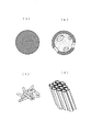
図1は、本願発明実施例の過熱蒸気発生装置の概略説明図を示すものであり、図2は通気性非加熱体の実施例を示す図である。
図中、1は筒状体、1aは筒状体の一方端、1bは筒状体の他方端、2は噴射水の導入ノズル、3は過熱蒸気の噴出口である。また、4は通気性被加熱体、5は励磁コイル、6は被覆材、7は導管、8は加圧水蒸気発生装置、40はパンチングメタル板である。なお、HVは過熱蒸気、V1、V2は開閉弁、V3、V4は逆止弁である。
図1において、導電体材料製の筒状体1の一方端1aには噴射水の導入ノズル2を備え、他方端1bには過熱蒸気の噴出口3を備えている。
筒状体1は外周面がキャスタブル耐火物セラミックス製の被覆材6で覆われ、断熱されている。そして、そのセラミックス被覆材6の外周面に高周波電流を通電する励磁コイル5が巻回され、図示しない高周波電流電源に接続されている。
また、筒状体1内には導電体材料製の通気性被加熱体4(図1においてはステンレススチール製の球体(図2(a)参照))が装填されており、励磁コイル5による電磁誘導で発熱加熱され、そこを通過する水又は水蒸気が高温加熱されて過熱蒸気HVとなって、他方端1bの噴出口3から噴出する。40はパンチングメタル板である。
なお、筒状体1の一方端1aに設けられている噴射水の導入ノズル2は、導管7を経由して送水ポンプPに接続され、また、加圧水蒸気発生装置8に接続されている。
噴射水の導入ノズル2から筒状体1内へ噴射水を噴射するには、加圧水蒸気発生装置8からの導管の途中に設けられた開閉弁V2を閉じ、開閉弁V1を開く。また、筒状体1内へ噴射水と加圧水蒸気を噴射するには、開閉弁V2を開き、開閉弁V1も開く。なお、V3及びV4は逆止弁である。
Next, an embodiment of the present invention will be described with reference to the drawings.
FIG. 1 is a schematic explanatory diagram of a superheated steam generator according to an embodiment of the present invention, and FIG. 2 is a diagram illustrating an embodiment of a gas-permeable non-heated body.
In the figure, 1 is a cylindrical body, 1a is one end of the cylindrical body, 1b is the other end of the cylindrical body, 2 is a nozzle for introducing jet water, and 3 is an outlet for superheated steam.
In FIG. 1, one
The outer peripheral surface of the cylindrical body 1 is covered with a
A
In addition, the
In order to inject the jet water from the
本願発明においては、導電体材料製の通気性被加熱体4が装填された筒状体1の一方端1aから筒状体1内に水又は水及び水蒸気を噴射し、次いで同筒状体1内に装填された前記通気性被加熱体4を水又は水蒸気が通過する。その際、前記通気性被加熱体4が励磁コイル5による電磁誘導で発熱加熱されているので、そこを通過する水又は水蒸気は高温加熱されて、筒状体1の他方端1bの噴出口3から過熱蒸気HVとなって噴出する。
なお、40はパンチングメタル板である。前記パンチングメタル40は、筒状体1内に装填された前記通気性被加熱体4が筒状体1の外に流出するのを防止している。
In the present invention, water or water and water vapor are injected into the tubular body 1 from one
水を噴射して同筒状体1内に装填された前記通気性被加熱体4を高周波誘導加熱すると、筒状体内に水蒸気を導入して加熱する場合に比べて、数10倍〜1000倍量程度の過熱水蒸気を発生することができる。よって高圧の過熱水蒸気を筒状体の他方端から容易に噴出せしめることができる。
すなわち、22.4リットルの水蒸気は18gであるが、18mlの水は18gであるため、理論的には18mlの水を筒状体1内に噴射すれば、22,400mlの水蒸気が生成することとなり、結局22,400ml÷18ml≒1240、よって水を噴射加熱する場合は水蒸気を導入加熱する場合に比して約1200倍もの大量の加圧水蒸気が生成することとなる。したがって、生成する加圧水蒸気の圧力も非常に高いものとなる。
When high-frequency induction heating is performed on the air-permeable heated
That is, 22.4 liters of water vapor is 18 g, but 18 ml of water is 18 g. Therefore, if 18 ml of water is theoretically injected into the cylindrical body 1, 22,400 ml of water vapor is generated. As a result, 22,400 ml ≒ 18 ml ≒ 1240, so that when water is injected and heated, a large amount of pressurized steam is generated which is about 1200 times larger than when steam is introduced and heated. Therefore, the pressure of the generated pressurized steam becomes very high.
なお、水又は水蒸気は、筒状体1内を通過する際に、加熱された通気性被加熱体4に接触し、さらに加熱されて過熱蒸気となり、徐々に膨張させられながら筒状体1の排出側へ臨ませられることになる。
筒状体1内の温度が上昇して励磁コイル5の電源を切っても、通気性被加熱体4が高温状態にあり、これが冷えることによって筒状体1内の温度が下がるため、冷却にも時間を要することになる。
When passing through the inside of the cylindrical body 1, the water or the steam comes into contact with the heated air-permeable heated
Even if the temperature in the tubular body 1 rises and the power of the
導電体材料としては、鉄などの強い磁性の金属、ステンレススチール430・403・304、ニッケル、チタン等の弱い磁性の金属の他、カーボンセラミックを使用することができる。磁性部材は、タンク内において蒸気を円滑に通過させる必要があり、棒体、線材、板材、ハニカム材、網体、球体、中空球体又は不定形塊状体等を使用することができる。それらには透孔を穿設しておいてもよい。 As the conductive material, carbon ceramic can be used in addition to strong magnetic metal such as iron, stainless steel 430, 403, 304, weak magnetic metal such as nickel and titanium. The magnetic member needs to allow steam to smoothly pass through the tank, and may be a rod, a wire, a plate, a honeycomb, a net, a sphere, a hollow sphere, an irregular mass, or the like. They may be perforated.
1 筒状体
1a 筒状体1の一方端
1b 筒状体1の他方端
2 噴射水の導入ノズル
3 過熱蒸気の噴出口
4 通気性被加熱体
5 励磁コイル
6 被覆材
7 導管
8 加圧水蒸気発生装置
40 パンチングメタル板
HV 過熱蒸気
V1、V2 開閉弁
V3、V4 逆止弁
DESCRIPTION OF SYMBOLS 1
Claims (10)
Water and steam are injected into the cylinder from one end of the tubular body loaded with the air-permeable heated body made of a conductive material, and then the high-frequency induction heating of the air-permeable heated body loaded in the tubular body is performed. A method of generating high-pressure superheated steam by causing high-temperature superheated steam to be ejected from the other end of the cylindrical body.
Applications Claiming Priority (1)
| Application Number | Priority Date | Filing Date | Title |
|---|---|---|---|
| JP2003019574 | 2003-01-28 |
Related Parent Applications (1)
| Application Number | Title | Priority Date | Filing Date |
|---|---|---|---|
| JP2003019574 Division | 2003-01-28 | 2003-01-28 |
Publications (1)
| Publication Number | Publication Date |
|---|---|
| JP2004233040A true JP2004233040A (en) | 2004-08-19 |
Family
ID=32820611
Family Applications (2)
| Application Number | Title | Priority Date | Filing Date |
|---|---|---|---|
| JP2005504721A Pending JPWO2004068033A1 (en) | 2003-01-28 | 2004-01-28 | Superheated steam generator |
| JP2004022189A Pending JP2004233040A (en) | 2003-01-28 | 2004-01-29 | Superheated steam generator |
Family Applications Before (1)
| Application Number | Title | Priority Date | Filing Date |
|---|---|---|---|
| JP2005504721A Pending JPWO2004068033A1 (en) | 2003-01-28 | 2004-01-28 | Superheated steam generator |
Country Status (5)
| Country | Link |
|---|---|
| US (1) | US20060236957A1 (en) |
| EP (1) | EP1591719A4 (en) |
| JP (2) | JPWO2004068033A1 (en) |
| CN (1) | CN1745279A (en) |
| WO (1) | WO2004068033A1 (en) |
Cited By (6)
| Publication number | Priority date | Publication date | Assignee | Title |
|---|---|---|---|---|
| JP2007101087A (en) * | 2005-10-05 | 2007-04-19 | Japan Fine Ceramics Center | Superheated steam generator, and superheated steam utilizing device |
| WO2007069855A1 (en) * | 2005-12-14 | 2007-06-21 | Jaeyoung Solutec Co., Ltd | Device for generating the superheated steam |
| CN101881480A (en) * | 2010-07-16 | 2010-11-10 | 辛海云 | Pipeline electromagnetic heating furnace |
| CN102829464A (en) * | 2012-09-27 | 2012-12-19 | 段伟 | Overheat vapor generator |
| JPWO2011043434A1 (en) * | 2009-10-07 | 2013-03-04 | 日本碍子株式会社 | Honeycomb structure |
| JP2014515873A (en) * | 2011-04-30 | 2014-07-03 | ハリー・ディーン・カッセル | Electric induction heating assembly |
Families Citing this family (6)
| Publication number | Priority date | Publication date | Assignee | Title |
|---|---|---|---|---|
| US8343422B2 (en) | 2008-08-08 | 2013-01-01 | Chokichi Sato | Water vapor plasma generating apparatus, sterilization and disinfection method, and method for antioxidative treatment using water vapor plasma |
| CN102785302A (en) * | 2012-08-23 | 2012-11-21 | 段伟 | Superheated steam plastic recycling device |
| US20160205727A1 (en) * | 2014-11-26 | 2016-07-14 | Numerical Design, Inc. | Microfluidic-based apparatus and method vaporization of liquids using magnetic induction |
| FR3037618B1 (en) * | 2015-06-18 | 2017-07-07 | Snecma | ERGOL FEEDING SYSTEM OF AN IGNITER |
| KR101757756B1 (en) | 2016-11-25 | 2017-07-17 | 유동연 | Electromagnetic induction heating boiler using electrode plate and transformer |
| DE102017125666A1 (en) * | 2017-11-02 | 2019-05-02 | Elwema Automotive Gmbh | Apparatus and method for cleaning workpieces by means of a steam jet and steam generator therefor |
Family Cites Families (6)
| Publication number | Priority date | Publication date | Assignee | Title |
|---|---|---|---|---|
| JPS52109001A (en) * | 1976-03-09 | 1977-09-12 | Masahiko Kiyotani | Furnace water pipe boiler |
| WO1998029685A1 (en) * | 1996-12-26 | 1998-07-09 | Kabushiki Kaisha Seta Giken | Superheated steam generator |
| JP3684758B2 (en) * | 1997-06-06 | 2005-08-17 | 松下電器産業株式会社 | Steam generator |
| JP3894649B2 (en) * | 1998-02-09 | 2007-03-22 | 大旺建設株式会社 | Degradation treatment method for persistent substances |
| JP4236369B2 (en) * | 2000-07-04 | 2009-03-11 | 株式会社かんでんエンジニアリング | Superheated steam generator, heating device using the device, carbonization carbonization device, superheated steam injection device, and cooker |
| US6734405B2 (en) * | 2002-06-12 | 2004-05-11 | Steris Inc. | Vaporizer using electrical induction to produce heat |
-
2004
- 2004-01-28 EP EP04705930A patent/EP1591719A4/en not_active Withdrawn
- 2004-01-28 JP JP2005504721A patent/JPWO2004068033A1/en active Pending
- 2004-01-28 CN CN200480002988.XA patent/CN1745279A/en active Pending
- 2004-01-28 US US10/543,788 patent/US20060236957A1/en not_active Abandoned
- 2004-01-28 WO PCT/JP2004/000738 patent/WO2004068033A1/en not_active Application Discontinuation
- 2004-01-29 JP JP2004022189A patent/JP2004233040A/en active Pending
Cited By (8)
| Publication number | Priority date | Publication date | Assignee | Title |
|---|---|---|---|---|
| JP2007101087A (en) * | 2005-10-05 | 2007-04-19 | Japan Fine Ceramics Center | Superheated steam generator, and superheated steam utilizing device |
| WO2007069855A1 (en) * | 2005-12-14 | 2007-06-21 | Jaeyoung Solutec Co., Ltd | Device for generating the superheated steam |
| US8028664B2 (en) | 2005-12-14 | 2011-10-04 | Jaeyoung Solutec Co., Ltd. | Device for generating the superheated steam |
| JPWO2011043434A1 (en) * | 2009-10-07 | 2013-03-04 | 日本碍子株式会社 | Honeycomb structure |
| JP5654999B2 (en) * | 2009-10-07 | 2015-01-14 | 日本碍子株式会社 | Honeycomb structure |
| CN101881480A (en) * | 2010-07-16 | 2010-11-10 | 辛海云 | Pipeline electromagnetic heating furnace |
| JP2014515873A (en) * | 2011-04-30 | 2014-07-03 | ハリー・ディーン・カッセル | Electric induction heating assembly |
| CN102829464A (en) * | 2012-09-27 | 2012-12-19 | 段伟 | Overheat vapor generator |
Also Published As
| Publication number | Publication date |
|---|---|
| US20060236957A1 (en) | 2006-10-26 |
| CN1745279A (en) | 2006-03-08 |
| EP1591719A1 (en) | 2005-11-02 |
| EP1591719A4 (en) | 2006-04-26 |
| JPWO2004068033A1 (en) | 2006-05-18 |
| WO2004068033A1 (en) | 2004-08-12 |
Similar Documents
| Publication | Publication Date | Title |
|---|---|---|
| JP5240987B2 (en) | Superheated steam generator, superheated steam generator, and superheated steam generation method | |
| JP2004233040A (en) | Superheated steam generator | |
| CA2561118A1 (en) | Heating apparatus for vaporizer | |
| KR950015637A (en) | Oxidation treatment device and oxidation treatment method | |
| TW201739312A (en) | A method for start-up heating of an ammonia synthesis converter | |
| CN103229601B (en) | Method and apparatus for forming non-isothermal plasma jet | |
| KR102380593B1 (en) | A Magnetic Induction Type of an Evaporating Apparatus and a Humidifier Using the Same | |
| JP2007236878A (en) | Heating method of tank, pan and pot | |
| JP4399582B2 (en) | Gas heating device | |
| JP3390788B2 (en) | Method of generating high-frequency induction thermal plasma and method of decomposing organic halogen compound | |
| JP2002106801A (en) | Steam generator | |
| JP2009174768A (en) | Superheated steam generator | |
| US20110233061A1 (en) | Amplification of energetic reactions | |
| JP2007173253A (en) | Heat-treatment device | |
| USRE37800E1 (en) | Induction heated steam generating system | |
| JP2003100427A (en) | Steam generator | |
| JP3933493B2 (en) | Heat treatment device | |
| JP2008298408A (en) | Cooker | |
| KR101226520B1 (en) | Sterillization apparatus | |
| JP2006260955A (en) | Supercritical fluid plasma generating device and supercritical fluid plasma generating method | |
| JP6150175B2 (en) | Superheated steam treatment method and apparatus | |
| JP2004333089A (en) | Heating device | |
| EA200702681A1 (en) | METHOD AND INSTALLATION FOR INCREASING THE ENERGY OF COMBUSTION OF NATURAL GAS | |
| JP3465029B2 (en) | Decomposition equipment for organic halogen compounds using high frequency induction thermal plasma equipment | |
| JP2008307215A (en) | Smoke generator |
Legal Events
| Date | Code | Title | Description |
|---|---|---|---|
| A621 | Written request for application examination |
Free format text: JAPANESE INTERMEDIATE CODE: A621 Effective date: 20060124 |
|
| A131 | Notification of reasons for refusal |
Free format text: JAPANESE INTERMEDIATE CODE: A131 Effective date: 20070926 |
|
| A521 | Request for written amendment filed |
Free format text: JAPANESE INTERMEDIATE CODE: A523 Effective date: 20071126 |
|
| A521 | Request for written amendment filed |
Free format text: JAPANESE INTERMEDIATE CODE: A523 Effective date: 20071206 |
|
| A02 | Decision of refusal |
Free format text: JAPANESE INTERMEDIATE CODE: A02 Effective date: 20080116 |
|
| A521 | Request for written amendment filed |
Free format text: JAPANESE INTERMEDIATE CODE: A523 Effective date: 20080502 |
|
| A521 | Request for written amendment filed |
Free format text: JAPANESE INTERMEDIATE CODE: A523 Effective date: 20080502 |
|
| A521 | Request for written amendment filed |
Free format text: JAPANESE INTERMEDIATE CODE: A523 Effective date: 20080611 |