JP2004229062A - Three-dimensional image display device and method for manufacturing same - Google Patents
Three-dimensional image display device and method for manufacturing same Download PDFInfo
- Publication number
- JP2004229062A JP2004229062A JP2003015933A JP2003015933A JP2004229062A JP 2004229062 A JP2004229062 A JP 2004229062A JP 2003015933 A JP2003015933 A JP 2003015933A JP 2003015933 A JP2003015933 A JP 2003015933A JP 2004229062 A JP2004229062 A JP 2004229062A
- Authority
- JP
- Japan
- Prior art keywords
- display
- spacer
- display device
- dimensional image
- display screen
- Prior art date
- Legal status (The legal status is an assumption and is not a legal conclusion. Google has not performed a legal analysis and makes no representation as to the accuracy of the status listed.)
- Pending
Links
- 238000004519 manufacturing process Methods 0.000 title claims description 12
- 238000000034 method Methods 0.000 title claims description 7
- 125000006850 spacer group Chemical group 0.000 claims abstract description 44
- 238000007789 sealing Methods 0.000 claims description 34
- 239000002346 layers by function Substances 0.000 claims description 20
- 238000005401 electroluminescence Methods 0.000 claims description 8
- 239000010410 layer Substances 0.000 claims description 6
- 239000012780 transparent material Substances 0.000 claims description 4
- 238000002347 injection Methods 0.000 claims description 3
- 239000007924 injection Substances 0.000 claims description 3
- 239000000758 substrate Substances 0.000 description 8
- 239000007789 gas Substances 0.000 description 4
- 239000000853 adhesive Substances 0.000 description 3
- 230000001070 adhesive effect Effects 0.000 description 3
- 239000000463 material Substances 0.000 description 3
- 230000004048 modification Effects 0.000 description 3
- 238000012986 modification Methods 0.000 description 3
- QVGXLLKOCUKJST-UHFFFAOYSA-N atomic oxygen Chemical compound [O] QVGXLLKOCUKJST-UHFFFAOYSA-N 0.000 description 2
- 150000002894 organic compounds Chemical class 0.000 description 2
- 239000001301 oxygen Substances 0.000 description 2
- 229910052760 oxygen Inorganic materials 0.000 description 2
- 239000011347 resin Substances 0.000 description 2
- 229920005989 resin Polymers 0.000 description 2
- IJGRMHOSHXDMSA-UHFFFAOYSA-N Atomic nitrogen Chemical compound N#N IJGRMHOSHXDMSA-UHFFFAOYSA-N 0.000 description 1
- 230000002542 deteriorative effect Effects 0.000 description 1
- 229910001873 dinitrogen Inorganic materials 0.000 description 1
- 230000001747 exhibiting effect Effects 0.000 description 1
- 239000011521 glass Substances 0.000 description 1
- 230000005525 hole transport Effects 0.000 description 1
- 239000011261 inert gas Substances 0.000 description 1
- 150000002484 inorganic compounds Chemical class 0.000 description 1
- 229910010272 inorganic material Inorganic materials 0.000 description 1
- 239000004973 liquid crystal related substance Substances 0.000 description 1
- 239000011159 matrix material Substances 0.000 description 1
- 239000002184 metal Substances 0.000 description 1
- 239000012466 permeate Substances 0.000 description 1
Images


Classifications
-
- H—ELECTRICITY
- H04—ELECTRIC COMMUNICATION TECHNIQUE
- H04N—PICTORIAL COMMUNICATION, e.g. TELEVISION
- H04N13/00—Stereoscopic video systems; Multi-view video systems; Details thereof
- H04N13/30—Image reproducers
- H04N13/388—Volumetric displays, i.e. systems where the image is built up from picture elements distributed through a volume
- H04N13/395—Volumetric displays, i.e. systems where the image is built up from picture elements distributed through a volume with depth sampling, i.e. the volume being constructed from a stack or sequence of 2D image planes
Abstract
Description
【0001】
【発明の属する技術分野】
本発明は、立体映像表示装置及びその製造方法に関する。
【0002】
【従来技術】
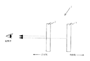
立体的な映像を表示する手段として、様々な方法を用いた装置が提起されている。例えば、図1に示す如く、明るさが異なる同一の平面像を重ねて表示するという立体映像装置1がある(例えば特許文献1参照。)。
立体映像表示装置1は、前面表示部2と背面表示部3とを有し、且つ背面表示部3の法線方向に前面表示部2が配置されている。前面表示部2は、背面表示部3の画像からの光を透過できる透明な表示パネル(以下透過型表示パネルと称する)である。前面表示部2と背面表示部3は、同一の画像であり且つ表示対象物の奥行き位置に応じて輝度が異なる対象物像からなる画像を各々表示する。前面表示部2に表示された画像からの光は前方方向に進行し、背面表示部3に表示された画像からの光は前面表示部2を介して前方方向に進行する。
【0003】
前方方向の観察者は、前面表示部2の画像と背面表示部3の画像が、奥行きの異なる2つの像として見えるのではなく、2つの像が融合した1つの像として見える。当該融合像を観察した観察者は、融合像を2つの像の輝度の比に応じて奥行きある立体映像として認識する。
かかる立体映像表示装置は、従来の表示装置に比べて自然な立体表示ができる故、観察者へ疲労感を与えることが少ない。
【0004】
【特許文献1】
特開2000−115812号公報
【0005】
【発明が解決しようとする課題】
上記の如き立体映像表示装置に衝撃が加えられた場合、表示部同士の相対的な位置が変動する。かかる表示部の変動によって、観察者に対する前後の像の表示位置が異なり、2つの像が融合しなくなる。その結果、観察者は立体的な映像を観察できなくなってしまうという問題がある。
【0006】
本発明が解決しようとする課題には、前述した問題が1例として挙げられる。
【0007】
【課題を解決するための手段】
請求項1に記載の立体映像表示装置は、少なくとも1つの透明な前方表示スクリーンを有する前方表示器と、前記前方表示スクリーンの後方に配置された後方表示スクリーンを有する後方表示器と、からなる立体映像表示装置であって、前記前方スクリーンが有機エレクトロルミネセンス素子を含み、前記前方表示器と前記後方表示器との間がスペーサによって充填されていることを特徴とする。
【0008】
請求項7に記載の立体映像表示装置の製造方法は、透明な前方表示スクリーンを少なくとも1つ有する前方表示器と、前記前方表示スクリーンの後方に配置された後方表示スクリーンを有する後方表示器と、からなる立体映像表示装置の製造方法であって、前記前方表示器を形成する前方表示器形成工程と、前記後方表示器を形成する後方表示器形成工程と、前記後方表示スクリーンの法線方向に沿って前方表示スクリーンを配し且つ前記前方表示器と前記後方表示器の間をスペーサによって充填するスペーサ充填工程と、を含み、前記前方表示器形成工程は有機エレクトロルミネセンス素子からなる有機エレクトロルミネセンス表示スクリーン形成工程を含むことを特徴とする。
【0009】
【発明の実施の形態】
本発明の立体映像表示装置の実施例を、添付図面を参照しつつ詳細に説明する。なお、立体映像表示装置の説明を簡単にするべく、外部回路、電極等を省略して記載する。
図2に示す如く、本発明による立体映像表示装置4は、透過型表示パネルである前方表示器5を有する。前方表示器5は、有機エレクトロルミネッセンス(以下有機ELと称する)素子を有する有機EL表示スクリーンを含む。有機EL表示スクリーンは、例えばパッシブマトリクス駆動方式による複数の有機EL素子からなる有機EL表示パネルである。
【0010】
前方表示器5は、透明材料からなる基板6を有する。基板6上には、エレクトロルミネセンスを呈する発光層を含む有機機能層7が設けられている。有機機能層7は、低分子系有機化合物及び高分子系有機化合物を含む。有機機能層7は、電子注入層、電子輸送層、正孔輸送層、正孔注入層等の複数の機能層を含んでも良い。
【0011】
有機機能層7は、透明材料からなる封止缶8によって覆われている。封止缶8は、外部から水分や酸素等の気体が透過しない材料からなる。有機機能層7が水分によって劣化し、非発光領域(いわゆるダークスポット)が発生することを防止するように、封止缶8によって外気が入らない封止構造を形成している。
前方表示器5の背面側には筒状のスペーサ9が設けられている。スペーサ9は、接着剤等の固定手段によって前方表示器5を固定している。スペーサ9は、樹脂、金属、ガラス等の材料からなる。
【0012】
スペーサ9を介して前方表示器5と対向する位置に、有機EL表示パネルである後方表示器10が配されている。後方表示器10は、固定手段によってスペーサ9に固定されている。後方表示器10も、前方表示器5と同様に基板11と有機機能層12と封止缶13とが設けられている。
上記の如き構造の立体映像表示装置4において、前方表示器5に表示された画像からの光は前面方向に出射し、後方表示器10に表示された画像からの光は、前方表示器5を介して前面方向に出射する。観察者は、前方表示器5に表示された画像からの光と後方表示器10に表示された画像からの光とが重ね合わされた融合光を見ることができる。
【0013】
かかる構成の立体映像表示装置は、表示器間にスペーサ9を配置して表示器同士を固定することによって、衝撃が与えられたとしても各表示器が相互に移動しない故、表示される立体映像を安定して表示することができる。
スペーサ9の高さは、任意に設定することができる。すなわち、立体映像表示装置4の表示器間の間隔が、所定の高さのスペーサ9で調整することができる。
【0014】
なお、スペーサの形状は、上記の如き筒状に限定されず、前方表示器と後方表示器の間隔を決定するものであれば良い。例えば、複数本数の柱状物でもよい。また、前方表示器5と後方表示器10の間に空洞14を設けなくても良い。例えば前方表示器と後方表示器の間に透明材料からなる板状部材が挟持されていても良い。更に、立体映像表示装置を組立てた後に、立体映像の表示状態を調整できるように、スペーサは、自身の高さを変更できる伸縮機構等の調整機構を備えても良い。
【0015】
スペーサ9は、反射抑制構造を有することが好ましい。例えば、スペーサ9の内壁面15に反射防止膜を設けても良い。スペーサ9が反射抑制構造を有することによって、表示スクリーン間で発生した散乱光がスペーサにて反射され且つ前面方向へ出射することを抑制できる。その結果、立体映像をより鮮明に表示することができる。
【0016】
スペーサ9は気体不透過特性を有する材料からなっても良い。スペーサが気体不透過特性を有することによって、スペーサと後方表示器の基板とが封止構造を形成することができる。該封止構造を設けることによって、図3に示す如く、立体映像表示装置4Aは、前方表示器5Aの封止缶を設けなくても良い。かかる構造において、スペーサ9Aと前方表示器の基板6Aと後方表示器の基板11Aとは、機密性を保つ接着剤等で接着されている。また、前方表示器5Aと後方表示器10Aとの間の空洞14Aは、窒素ガス等の不活性ガスが充填され且つ乾燥状態にあることが好ましい。上記変形例は、封止缶による封止代を考慮しなくても良いことから、両表示器間の間隔を小とすることができる。
【0017】
また、封止缶を設けないことによって封止缶の表面における光の反射が発生しなくなり、当該反射光によって像がぼやけることが防止できる故、表示対象物の輪郭が明瞭な立体映像が観察できる。
図4に示す如く、後方表示器10Bの有機機能層12Bを空洞14B内に配しても良い。かかる構成によれば、スペーサ9Bと前方表示器5Bと後方表示器10Bとによって有機機能層を封止することができる。すなわち、封止缶を使用することなく立体映像表示装置を形成することができる。
【0018】
次に、上記実施例の立体映像表示装置の製造方法について説明する。立体映像表示装置の製造工程は、前方表示器形成工程と前記後方表示器を形成する後方表示器形成工程を含む。前方表示器形成工程は有機EL素子からなる有機EL表示スクリーン形成工程を含む。有機EL表示スクリーン形成工程は、基板に有機機能層を形成する有機機能層形成工程を少なくとも含む。また、封止缶によって有機機能層を封止する有機機能層封止工程を含んでも良い。
【0019】
前方及び後方の表示器を形成した後、後方表示器の後方表示スクリーンの法線方向に沿って前方表示器の前方表示スクリーンを配し且つ前方表示器と後方表示器の間にスペーサを充填するスペーサ充填工程を行う。スペーサ充填工程は、スペーサと表示器を接着剤等の固定部材を用いて固定する工程を含む。上記工程によって立体映像表示装置が完成する。
【0020】
上記の如き製造方法によれば、表示器同士をスペーサで固定して一体とすることができる故、安定して立体映像を表示できる立体映像表示装置が形成できる。有機EL表示パネルの有機機能層形成工程を行った後に、表示パネルとスペーサが形成する封止構造内に当該有機機能層を封止する封止工程を行うことで、図3及び図4に示す如き立体映像表示装置が形成できる。封止工程で形成される封止構造は、水分や酸素等のガスの出入りを遮断する構造である。すなわち、封止構造内に有機機能層を配すれば、有機機能層を覆う封止缶を設けることなく立体映像表示装置を形成することができる故、製造工程の削減を図ることができる。
【0021】
なお、上記した全ての実施例において、封止缶の代わりに樹脂等からなる封止フィルムやSiN等の無機化合物からなる封止膜を含む封止部材を用いても良い。かかる封止部材を用いることによって、表示パネルの軽量化及び薄型化を図ることができる。
前方表示器及び後方表示器の表示スクリーンは、液晶パネル等の他の画像表示手段を用いても良い。また、前方表示器は、前方表示スクリーンを2枚以上含んでも良い。
【0022】
少なくとも1つの透明な前方表示スクリーンを有する前方表示器と、前記前方表示スクリーンの後方に配置された後方表示スクリーンを有する後方表示器と、からなる立体映像表示装置であって、前記前方スクリーンが有機エレクトロルミネセンス素子を含み、前記前方表示器と前記後方表示器との間がスペーサによって充填されていることを特徴とする立体映像表示装置によれば、スペーサの高さが表示器間の間隔となる故、任意の高さのスペーサを用いることによって表示器間の間隔を調整することができる。
【0023】
透明な前方表示スクリーンを少なくとも1つ有する前方表示器と、前記前方表示スクリーンの後方に配置された後方表示スクリーンを有する後方表示器と、からなる立体映像表示装置の製造方法であって、前記前方表示器を形成する前方表示器形成工程と、前記後方表示器を形成する後方表示器形成工程と、前記後方表示スクリーンの法線方向に沿って前方表示スクリーンを配し且つ前記前方表示器と前記後方表示器の間をスペーサによって充填するスペーサ充填工程と、を含み、前記前方表示器形成工程は有機エレクトロルミネセンス素子からなる有機エレクトロルミネセンス表示スクリーン形成工程を含むことを特徴とする立体映像表示装置の製造方法によれば、表示器同士がスペーサを介して固定される故、安定して明瞭な立体映像を表示できる立体映像表示装置を提供できる。
【図面の簡単な説明】
【図1】従来の立体映像表示装置の構造を示す断面図である。
【図2】本発明による立体映像表示装置の構造を示す断面図である。
【図3】本発明による立体映像表示装置の変形例を示す断面図である。
【図4】本発明による立体映像表示装置の変形例を示す断面図である。
【符号の説明】
1、4 立体映像表示装置
5 前方表示器
6、11 基板
7、12 有機機能層
8、13 封止缶
9 スペーサ
10 後方表示器
14 空洞
15 内壁面[0001]
TECHNICAL FIELD OF THE INVENTION
The present invention relates to a three-dimensional image display device and a method for manufacturing the same.
[0002]
[Prior art]
Devices using various methods have been proposed as means for displaying a stereoscopic video. For example, as shown in FIG. 1, there is a
The stereoscopic
[0003]
A viewer in the forward direction sees the image on the
Such a three-dimensional image display device can provide a natural three-dimensional display as compared with a conventional display device, and therefore does not give the viewer a feeling of fatigue.
[0004]
[Patent Document 1]
JP 2000-115812 A
[Problems to be solved by the invention]
When an impact is applied to the three-dimensional image display device as described above, the relative positions of the display units change. Due to such a change in the display unit, the display positions of the front and rear images for the observer differ, and the two images do not fuse. As a result, there is a problem that a viewer cannot observe a stereoscopic image.
[0006]
The problem to be solved by the present invention includes the above-mentioned problem as an example.
[0007]
[Means for Solving the Problems]
The three-dimensional image display device according to
[0008]
The method of manufacturing a stereoscopic image display device according to
[0009]
BEST MODE FOR CARRYING OUT THE INVENTION
Embodiments of the stereoscopic video display device of the present invention will be described in detail with reference to the accompanying drawings. Note that, in order to simplify the description of the three-dimensional image display device, an external circuit, electrodes, and the like are omitted.
As shown in FIG. 2, the stereoscopic
[0010]
The
[0011]
The organic
A
[0012]
A
In the three-dimensional
[0013]
In the three-dimensional image display device having such a configuration, the three-dimensional image to be displayed is displayed by disposing the
The height of the
[0014]
The shape of the spacer is not limited to the cylindrical shape as described above, and may be any as long as it determines the distance between the front display and the rear display. For example, a plurality of columnar objects may be used. Further, the
[0015]
The
[0016]
The
[0017]
In addition, by not providing the sealing can, reflection of light on the surface of the sealing can does not occur, and an image can be prevented from being blurred by the reflected light, so that a stereoscopic image with a clear outline of the display object can be observed. .
As shown in FIG. 4, the organic functional layer 12B of the rear display 10B may be disposed in the cavity 14B. According to such a configuration, the organic functional layer can be sealed by the spacer 9B, the front display 5B, and the rear display 10B. That is, a three-dimensional image display device can be formed without using a sealing can.
[0018]
Next, a method of manufacturing the stereoscopic video display device of the above embodiment will be described. The manufacturing process of the stereoscopic image display device includes a front display forming step and a rear display forming step of forming the rear display. The front display forming step includes an organic EL display screen forming step made up of organic EL elements. The organic EL display screen forming step includes at least an organic functional layer forming step of forming an organic functional layer on the substrate. Further, an organic functional layer sealing step of sealing the organic functional layer with a sealing can may be included.
[0019]
After forming the front and rear indicators, the front display screen of the front indicator is arranged along the normal direction of the rear display screen of the rear indicator, and a spacer is filled between the front indicator and the rear indicator. A spacer filling step is performed. The spacer filling step includes a step of fixing the spacer and the display using a fixing member such as an adhesive. Through the above steps, a stereoscopic video display device is completed.
[0020]
According to the manufacturing method as described above, the displays can be fixed to each other by the spacers and integrated, so that a stereoscopic video display device capable of stably displaying a stereoscopic video can be formed. After performing the organic functional layer forming step of the organic EL display panel, a sealing step of sealing the organic functional layer in a sealing structure formed by the display panel and the spacer is performed, as shown in FIGS. 3 and 4. Such a three-dimensional image display device can be formed. The sealing structure formed in the sealing step is a structure that blocks entry and exit of a gas such as moisture or oxygen. That is, if the organic functional layer is provided in the sealing structure, the three-dimensional image display device can be formed without providing a sealing can that covers the organic functional layer, so that the number of manufacturing steps can be reduced.
[0021]
In all the above-described embodiments, a sealing member including a sealing film made of a resin or the like or a sealing film made of an inorganic compound such as SiN may be used instead of the sealing can. By using such a sealing member, the weight and thickness of the display panel can be reduced.
The display screens of the front display and the rear display may use other image display means such as a liquid crystal panel. Further, the front display may include two or more front display screens.
[0022]
A stereoscopic image display device comprising: a front display having at least one transparent front display screen; and a rear display having a rear display screen disposed behind the front display screen, wherein the front screen is an organic display. According to the stereoscopic image display device including an electroluminescence element, wherein the space between the front display and the rear display is filled with a spacer, the height of the spacer is equal to the distance between the displays. Therefore, the spacing between the displays can be adjusted by using a spacer having an arbitrary height.
[0023]
A method of manufacturing a three-dimensional image display device, comprising: a front display having at least one transparent front display screen; and a rear display having a rear display screen disposed behind the front display screen, wherein the front display is provided. A front display forming step of forming a display, a rear display forming step of forming the rear display, a front display screen arranged along a normal direction of the rear display screen, and the front display and the front display; A space filling step of filling a space between the rear displays with a spacer, wherein the front display forming step includes an organic electroluminescence display screen forming step including an organic electroluminescence element. According to the manufacturing method of the device, since the displays are fixed to each other via the spacer, a stable and clear stereoscopic image is obtained. It can provide a stereoscopic image display device capable shown.
[Brief description of the drawings]
FIG. 1 is a cross-sectional view illustrating a structure of a conventional stereoscopic image display device.
FIG. 2 is a cross-sectional view illustrating a structure of a stereoscopic image display device according to the present invention.
FIG. 3 is a sectional view showing a modification of the stereoscopic video display device according to the present invention.
FIG. 4 is a sectional view showing a modification of the stereoscopic video display device according to the present invention.
[Explanation of symbols]
1, 4 stereoscopic
Claims (8)
前記前方スクリーンが有機エレクトロルミネセンス素子を含み、
前記前方表示器と前記後方表示器との間がスペーサによって充填されていることを特徴とする立体映像表示装置。A stereoscopic video display device comprising: a front display having at least one transparent front display screen; and a rear display having a rear display screen disposed behind the front display screen,
The front screen includes an organic electroluminescent element,
A three-dimensional image display device, wherein a space between the front display and the rear display is filled with a spacer.
前記前方表示器を形成する前方表示器形成工程と、
前記後方表示器を形成する後方表示器形成工程と、
前記後方表示スクリーンの法線方向に沿って前方表示スクリーンを配し且つ前記前方表示器と前記後方表示器の間をスペーサによって充填するスペーサ充填工程と、を含み、
前記前方表示器形成工程は有機エレクトロルミネセンス素子からなる有機エレクトロルミネセンス表示スクリーン形成工程を含むことを特徴とする立体映像表示装置の製造方法。A method for manufacturing a stereoscopic image display device, comprising: a front display having at least one transparent front display screen; and a rear display having a rear display screen disposed behind the front display screen,
A front display forming step of forming the front display;
A rear display forming step of forming the rear display;
A spacer filling step of arranging a front display screen along a normal direction of the rear display screen and filling a space between the front display and the rear display with a spacer.
The method of manufacturing a three-dimensional image display device according to claim 1, wherein the step of forming a front display includes a step of forming an organic electroluminescence display screen comprising an organic electroluminescence element.
前記スペーサ配置工程は前記前方表示器と前記後方表示器と前記スペーサとによって外部から気体が入らない封止構造を形成する封止工程を含み、
前記封止工程は前記有機機能層を前記封止構造内に封止する工程であることを特徴とする請求項7記載の立体映像表示装置の製造方法。The organic electroluminescence display screen forming step includes an organic functional layer forming step having a light emitting layer that emits light by current injection,
The spacer disposing step includes a sealing step of forming a sealing structure in which gas does not enter from the outside by the front display, the rear display, and the spacer,
8. The method according to claim 7, wherein the sealing step is a step of sealing the organic functional layer in the sealing structure.
Priority Applications (2)
| Application Number | Priority Date | Filing Date | Title |
|---|---|---|---|
| JP2003015933A JP2004229062A (en) | 2003-01-24 | 2003-01-24 | Three-dimensional image display device and method for manufacturing same |
| US10/758,531 US20040145537A1 (en) | 2003-01-24 | 2004-01-16 | Apparatus for displaying a three-dimensional image and process of making the same |
Applications Claiming Priority (1)
| Application Number | Priority Date | Filing Date | Title |
|---|---|---|---|
| JP2003015933A JP2004229062A (en) | 2003-01-24 | 2003-01-24 | Three-dimensional image display device and method for manufacturing same |
Publications (1)
| Publication Number | Publication Date |
|---|---|
| JP2004229062A true JP2004229062A (en) | 2004-08-12 |
Family
ID=32732813
Family Applications (1)
| Application Number | Title | Priority Date | Filing Date |
|---|---|---|---|
| JP2003015933A Pending JP2004229062A (en) | 2003-01-24 | 2003-01-24 | Three-dimensional image display device and method for manufacturing same |
Country Status (2)
| Country | Link |
|---|---|
| US (1) | US20040145537A1 (en) |
| JP (1) | JP2004229062A (en) |
Cited By (1)
| Publication number | Priority date | Publication date | Assignee | Title |
|---|---|---|---|---|
| JP2008233317A (en) * | 2007-03-19 | 2008-10-02 | Seiko Epson Corp | Display and electronic device |
Families Citing this family (2)
| Publication number | Priority date | Publication date | Assignee | Title |
|---|---|---|---|---|
| KR101622307B1 (en) * | 2009-07-02 | 2016-05-18 | 삼성전자주식회사 | Three-dimensional image display apparatus and method |
| CN105100777B (en) * | 2015-08-26 | 2017-04-19 | 南京中科神光科技有限公司 | Three-dimensional multi-content display method and apparatuses |
Family Cites Families (11)
| Publication number | Priority date | Publication date | Assignee | Title |
|---|---|---|---|---|
| FI60333C (en) * | 1980-04-24 | 1981-12-10 | Lohja Ab Oy | Electro-luminescent-AOTERGIVNINGSKOMPONENT |
| US4719385A (en) * | 1985-04-26 | 1988-01-12 | Barrow William A | Multi-colored thin-film electroluminescent display |
| FR2602606B1 (en) * | 1986-08-11 | 1988-11-10 | Pecile Dario | ELECTROLUMINESCENT FLAT SCREEN |
| JPS63224190A (en) * | 1987-03-12 | 1988-09-19 | 株式会社日立製作所 | El device and method of emitting light |
| US5220317A (en) * | 1990-12-11 | 1993-06-15 | Donnelly Corporation | Electrochromic device capable of prolonged coloration |
| US5757127A (en) * | 1994-06-10 | 1998-05-26 | Nippondenso Co., Ltd. | Transparent thin-film EL display apparatus with ambient light adaptation means |
| GB9507862D0 (en) * | 1995-04-18 | 1995-05-31 | Cambridge Display Tech Ltd | Fabrication of organic light-emitting devices |
| US5973831A (en) * | 1996-01-22 | 1999-10-26 | Kleinberger; Paul | Systems for three-dimensional viewing using light polarizing layers |
| JP3577821B2 (en) * | 1996-02-13 | 2004-10-20 | 株式会社デンソー | EL display device |
| US6525699B1 (en) * | 1998-05-21 | 2003-02-25 | Nippon Telegraph And Telephone Corporation | Three-dimensional representation method and an apparatus thereof |
| JP2003234186A (en) * | 2001-12-06 | 2003-08-22 | Sony Corp | Display device, and manufacturing method of the same |
-
2003
- 2003-01-24 JP JP2003015933A patent/JP2004229062A/en active Pending
-
2004
- 2004-01-16 US US10/758,531 patent/US20040145537A1/en not_active Abandoned
Cited By (1)
| Publication number | Priority date | Publication date | Assignee | Title |
|---|---|---|---|---|
| JP2008233317A (en) * | 2007-03-19 | 2008-10-02 | Seiko Epson Corp | Display and electronic device |
Also Published As
| Publication number | Publication date |
|---|---|
| US20040145537A1 (en) | 2004-07-29 |
Similar Documents
| Publication | Publication Date | Title |
|---|---|---|
| KR101170798B1 (en) | Volumetric 3D display system using multi-layer organic light emitting device | |
| JP5063296B2 (en) | Electronic video equipment | |
| EP2755251B1 (en) | Organic light-emitting diode (OLED) display panel | |
| WO2003063512A3 (en) | Multi-layer display | |
| KR101394059B1 (en) | Transparent display panel for stereographic image | |
| US20070047058A1 (en) | Barrier and image display device with the same | |
| US11088213B1 (en) | Display substrate, display apparatus, method of controlling display substrate, and method of fabricating display substrate | |
| US20020075566A1 (en) | 3D or multiview light emitting display | |
| US20140232757A1 (en) | Display device and electronic apparatus | |
| KR101837325B1 (en) | 3d display panel with effect of depth of field, and display method therefor | |
| JP5021937B2 (en) | 3D display device | |
| JP2011107712A (en) | Stereoscopic image display device, electronic device and driving method of stereoscopic image display device | |
| KR102463582B1 (en) | Multi-view display device | |
| JP2001005414A (en) | Multidisplay device | |
| JP2004226856A (en) | Display device | |
| JP2005093223A (en) | Display panel, manufacturing method of same, and display device | |
| US20070236619A1 (en) | Image display device | |
| US7355563B2 (en) | Display apparatus and display device | |
| JP2004229062A (en) | Three-dimensional image display device and method for manufacturing same | |
| JP2009086024A (en) | Image display device and electronic device | |
| JP4864142B2 (en) | Surface emitting device | |
| JP2004127657A (en) | Image display device and its manufacturing method | |
| US20040160177A1 (en) | Electroluminescence display panel and three-dimensional display apparatus | |
| JPH07261677A (en) | Stereoscopic display device | |
| JP2010015077A (en) | Display device |
Legal Events
| Date | Code | Title | Description |
|---|---|---|---|
| A621 | Written request for application examination |
Free format text: JAPANESE INTERMEDIATE CODE: A621 Effective date: 20051219 |
|
| A977 | Report on retrieval |
Free format text: JAPANESE INTERMEDIATE CODE: A971007 Effective date: 20080819 |
|
| A131 | Notification of reasons for refusal |
Free format text: JAPANESE INTERMEDIATE CODE: A131 Effective date: 20080826 |
|
| A02 | Decision of refusal |
Free format text: JAPANESE INTERMEDIATE CODE: A02 Effective date: 20081224 |