JP2004209080A - Lock for game machine - Google Patents
Lock for game machine Download PDFInfo
- Publication number
- JP2004209080A JP2004209080A JP2003001249A JP2003001249A JP2004209080A JP 2004209080 A JP2004209080 A JP 2004209080A JP 2003001249 A JP2003001249 A JP 2003001249A JP 2003001249 A JP2003001249 A JP 2003001249A JP 2004209080 A JP2004209080 A JP 2004209080A
- Authority
- JP
- Japan
- Prior art keywords
- claw
- front panel
- slide plate
- swing
- swinging
- Prior art date
- Legal status (The legal status is an assumption and is not a legal conclusion. Google has not performed a legal analysis and makes no representation as to the accuracy of the status listed.)
- Granted
Links
- 230000001105 regulatory effect Effects 0.000 claims abstract description 33
- 210000000078 claw Anatomy 0.000 claims description 139
- 230000010355 oscillation Effects 0.000 abstract 6
- 230000000903 blocking effect Effects 0.000 abstract 1
- 238000010586 diagram Methods 0.000 description 8
- 230000003028 elevating effect Effects 0.000 description 2
- 230000007246 mechanism Effects 0.000 description 2
- 230000000149 penetrating effect Effects 0.000 description 2
- 230000000452 restraining effect Effects 0.000 description 2
- 230000006835 compression Effects 0.000 description 1
- 238000007906 compression Methods 0.000 description 1
- 230000001276 controlling effect Effects 0.000 description 1
- 230000000694 effects Effects 0.000 description 1
- 238000000034 method Methods 0.000 description 1
Images






Landscapes
- Pinball Game Machines (AREA)
- Slot Machines And Peripheral Devices (AREA)
Abstract
Description
【0001】
【発明の属する技術分野】
本発明は、例えば回胴式遊技機(所謂、パチスロ)に用いて好適な遊技機用施錠装置に関し、特に、扉と筐体との隙間から挿入される針金等による不正行為を防止する改良技術に関する。
【0002】
【従来の技術】
従来、遊技機の施錠装置として、例えば以下に示す特許文献1に開示されているものがある。これは、図14に示すように、前面枠100の開放側裏面にシリンダ錠101と、該シリンダ錠101の錠軸102に取付けられたカム板103と、上下一対の鉤片104,104を有する昇降杆105とを基枠体106を介して取り付けるとともに、外枠107の開放側内側面の上下位置に前記鉤片104,104が係脱する係止金具108,108を固着し、シリンダ錠101の回動操作によりカム板103を回動して昇降杆105を上下方向へ摺動させるとともに、係止金具108,108と鉤片104,104との係合を解除して前面枠100を解錠するように構成されたものである。
【0003】
【特許文献1】
実公昭58−4538号公報
【0004】
【発明が解決しようとする課題】
しかしながら、上記した遊技機用施錠装置は、前面枠100の開閉端側の裏面に、昇降杆105,カム板103とを配設し、これらの機構部が前面枠100の開閉端側の木口側に露出する状態となっていて、昇降杆105がカム板103だけによって上下摺動して、係止金具108に係脱する機構であったため、前面枠100を閉鎖した場合であっても、前面枠100と外枠107との隙間から針金等を挿入すれば、昇降杆105や鉤片104を係合解除する方向に直接移動させることも可能で、前面枠100が開放されてしまい、容易に内部装置(遊技用制御基板等)に触れて不正な行為、悪戯ができ、高い施錠信頼性を得ることができなかった。
【0005】
本発明は上記状況に鑑みてなされたもので、隙間から挿入される針金等によっても扉が開放できず、遊技用制御基板等への不正な行為を防止することのできる遊技機用施錠装置を提供し、施錠信頼性の向上を図ることを目的とする。
【0006】
【課題を解決するための手段】
次に、上記の課題を解決するための手段を、実施の形態に対応する図面を参照して説明する。
この発明の請求項1記載の遊技機用施錠装置7は、筺体3にヒンジを介して開閉動自在となったフロントパネル5に設けられ遊技機前後方向の回動中心21で回動し、かつ回動軸11aに固定されて連動するクランク軸9を有したシリンダー錠11と、
前記フロントパネル5に固定され前記筐体3側へ突出する先端L形の押圧爪13と、
前記筐体3に揺動自在に設けられ前記フロントパネル5の閉動に伴う該押圧爪13の押圧により揺動する一方、該揺動が規制されることで該押圧爪13をロックして前記フロントパネル5の開動を規制する揺動爪15と、
前記筐体3にスライド自在に設けられバネ31によって一方向へ付勢されるとともに、前記クランク軸9の先端が角部33aに進入する係合穴33を有したスライド板17と、
該スライド板17に固着され該スライド板17の前記一方向のスライド位置で前記揺動爪15に係合して該揺動爪15の揺動を規制する一方、前記スライド板17の他方向のスライド位置で前記揺動爪15の回転規制を解除し、かつ揺動位置の該揺動爪15に係止して前記スライド板17を他方のスライド位置に保持する揺動規制爪19と、
を具備したことを特徴とする。
【0007】
この遊技機用施錠装置7では、押圧爪13に係止した揺動爪15が揺動規制爪19によってロックされ、この揺動規制爪19を固着したスライド板17が係合穴33を介してクランク軸9にロックされる。すなわち、スライド板17は、クランク軸9が係合穴33の角部33aに進入しているので、シリンダー錠11が解錠回転されなければ、スライドが不能となる。従って、筺体3とフロントパネル5との隙間から針金等を挿入しても、揺動爪15は揺動規制爪19に揺動が規制され、スライド板17は係合穴33を介してクランク軸9にスライドが規制されるので、押圧爪13と揺動爪15との係止を直接に動かして解除することができず、このような不正行為によるフロントパネル5の解錠が阻止される。また、フロントパネル5を閉動することにより、揺動爪15が押圧爪13に押圧されてロック方向に回転するので、フロントパネル5を閉動するのみでフロントパネル5を施錠することが可能となる。
【0008】
請求項2記載の遊技機用施錠装置7は、請求項1記載の遊技機用施錠装置7において、
前記スライド板17のスライド方向両端部に、前記揺動規制爪19を固着し、一対の該揺動規制爪19に対応させて一対の前記揺動爪15を前記筐体3に設け、
一対の該揺動爪15に対応させて一対の前記押圧爪13を前記フロントパネル5に固定したことを特徴とする。
【0009】
この遊技機用施錠装置7では、スライド板17のスライド方向両端部に揺動規制爪19が固着され、この一対の揺動規制爪19に対応させて一対の揺動爪15が筐体3に設けられ、この一対の揺動爪15に対応させて一対の押圧爪13がフロントパネル5に固定されているので、フロントパネル5を閉鎖すると、一対の押圧爪13が、一対の揺動爪15にロックされることとなる。従って、一つのスライド板17を用いて、二つの揺動爪15が作動され、フロントパネル5と筺体3とが、二組の押圧爪13及び揺動爪15で施錠可能となって、フロントパネル5の施錠信頼性が高められる。
【0010】
【発明の実施の形態】
以下、本発明に係る遊技機用施錠装置の好適な実施の形態を図面を参照して詳細に説明する。
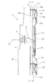
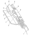
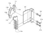
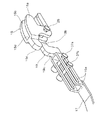
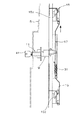
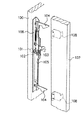
図1は本発明に係る遊技機用施錠装置の側面図、図2は図1のA−A線断面図、図3は図1に示した遊技機用施錠装置の斜視図、図4はシリンダ錠の側面図を(a)に、一部裁断底面図を(b)に、背面図を(c)に示した構成図、図5は揺動爪及び揺動規制爪の側面図を(a)に、正面図を(b)に、底面図を(c)に示した構成図、図6は揺動爪及び揺動規制爪の斜視図、図7は図6の分解斜視図、図8は図6の固定板を省略した斜視図、図9は揺動状態の揺動爪を表す斜視図、図10は図9の固定板を省略した斜視図である。
【0011】
図1,図2に示すように、例えば回胴式遊技機である所謂、パチスロ等の遊技機1は、ヒンジ(図示せず)によって筐体3に対して開閉自在となった扉であるフロントパネル5を有している。フロントパネル5は、図示しないが、複数の操作スイッチや、筺体3に設けた回胴を目視可能とする窓部等を有している。遊技機1は、上記の回胴を回転する回転制御装置(図示せず)、操作スイッチ、遊技媒体払出し装置(図示せず)や、これらと電気的に接続され、回胴の回転や遊技媒体払出し数等を制御する遊技用制御基板等(図示せず)を筺体3に備えている。遊技機1は、これらの内部装置が、フロントパネル5を筺体3に対して閉鎖することにより外部から覆われている。
【0012】
本実施の形態による遊技機用施錠装置7は、筺体3に対してフロントパネル5を施解錠するためのものである。図3に示すように、遊技機用施錠装置7は、クランク軸9を有したシリンダー錠11と、押圧爪13(図1参照)と、揺動爪15と、スライド板17と、揺動規制爪19とを主要な構成要素として有している。
【0013】
フロントパネル5は、図示しないヒンジを介して左右方向の一端側が筐体3に回動自在に支持され、左右方向の他端側が筐体3に対して開閉動される。シリンダー錠11は、このフロントパネル5の開閉動される他端側に取付けられ、鍵穴11aをフロントパネル5の前面に表出させている。つまり、シリンダー錠11は、遊技機1の前後方向の回動中心21(図1参照)で回動する。クランク軸9は、図4に示すシリンダー錠11の回動軸11aに基端軸9aが固定され、クランク状に折り曲げられた先端軸9bが基端軸9aに対して偏芯している。クランク軸9は、先端軸9bが筐体3に向かって突出している。
【0014】
押圧爪13は、フロントパネル5の背面の上下に位置し固定される。押圧爪13は、先端が例えば下方へ折れ曲がるL形となり、筐体3側へ向かって突出する。この押圧爪13は、後に詳述するようにL形先端13aで揺動爪15を押圧するとともに、このL形先端13aで揺動爪15に係止するようになっている。
【0015】
揺動爪15は、各押圧爪13に対応して、筐体3に一対のものが配設される。筐体3には略L形の固定板23が固定され、揺動爪15はこの固定板23の側板を貫通した支持ピン25によって揺動自在に取付けられている。この支持ピン25は、図1に示すように、軸線が遊技機1の左右方向となる。
【0016】
揺動爪15は、図5,図6に示すように、爪部15aが間隙15bを有して離間されている。この爪部15aの反対側には突起15cが突設されている。また、突起15cの背面部は、離間した爪部15aを連結して形成した掛止部15d(図6参照)となっている。さらに、爪部15aの延出方向と略同方向となって当接部15eが凹状の間隙部分を備えて突設されている。揺動爪15は、図5(a)に示すように、爪部15aで押圧爪13と係止する。そして、当接部15eとの間に凹状の間隙部分に嵌入される。
【0017】
筐体3には図3に示すベース板27が固定される。スライド板17は、このベース板27に立設された一対の規制ピン29a,29bに、長穴17a,17bを係合することで、遊技機1の上下方向にスライド自在となっている。ベース板27とスライド板17とにはバネ31が張架され、バネ31はスライド板17を一方向である図1の下方向へ付勢している。また、スライド板17には図2に示す角部33aを有する係合穴33が穿設されている。この係合穴33には、クランク軸9の先端軸9bが進入する。係合穴33に進入した先端軸9bは角部33aに配置されることで、スライド板17の上下方向のスライドを規制する。
【0018】
なお、クランク軸9の先端軸9bは、図4(b)に示すように、クランク軸9に対して抜脱を阻止し、かつ進退自在に嵌入してあり、圧縮バネ35によって先端軸9bを突出方向に付勢している。これにより、フロントパネル5の閉動時、仮にスライド不良によって先端軸9bが係合穴33以外に当接した場合であっても、先端軸9bが圧縮バネ35を圧縮してクランク軸9内に後退し、クランク軸9或いはスライド板17が破損しないようになっている。
【0019】
揺動規制爪19は、図1,図3に示すように、スライド板17の上下端に固着されている。また、揺動規制爪19は、図7に示すように、固定板23の側板を貫通した一対の支持ピン37a,37bによって、長穴19aを介してスライド方向にガイドされている。揺動規制爪19は、略L形に形成され、図8に示すように、先端部19bを揺動爪15の突起15cに当接して、揺動爪15の回転を規制する。また、揺動規制爪19は、スライド板17のスライドにより、図9,図10に示すように、揺動爪15の間隙15bに進入可能となっている。これにより、揺動爪15は、突起15cが揺動規制爪19に当接しなくなり、図9,図10に示すように図中反時計回りに回動可能となる。
【0020】
さらに、揺動規制爪19は、間隙15bに進入した状態で、揺動爪15が回転すると、別言するとフロントパネル5が開動されることにより押圧爪13に連れ回りして回転すると、図8に示す肩部19cが揺動爪15の掛止部15dに係止するようになっている(図9の状態)。これにより、揺動規制爪19は、揺動状態の揺動爪15に係止して、スライド板17の一方向(図12中下方向)へのスライドを規制するようになっている。つまり、スライド板17は、上方向にスライドされたまま保持される。この保持は、揺動爪15が押圧爪13に押圧されて回転されることにより解除される。肩部19cが掛止部15dから外れると、スライド板17は、再びバネ31の付勢力によって図中下側へスライドされることになる(図1の状態)。
【0021】
従って、揺動爪15は、フロントパネル5の閉動に伴う押圧爪13の押圧により揺動する一方、フロントパネル5の閉鎖時には、突起15cが揺動規制爪19の先端部19bに当接して揺動が規制されることで、押圧爪13をロック、すなわち揺動爪15に保持し、フロントパネル5の開動を規制するようになっている。
【0022】
次に、上記の構成を有する遊技機用施錠装置の作用を説明する。
図11はスライド板の上方スライド状態の動作説明図、図12はフロントパネル開動時の動作説明図、図13はフロントパネル閉動時の動作説明図である。
【0023】
図1に示すように、フロントパネル5の閉鎖状態では、スライド板17がバネ31の付勢力により、下方に配置され、揺動規制爪19の先端部19bが揺動爪15の突起15cに当接して(図6参照)、揺動爪15の回転を阻止している。従って、揺動爪15に押圧爪13を係止したフロントパネル5は、筐体3からの開放が不能となって施錠状態となる。
【0024】
一方、フロントパネル5を開放するのに、図11に示すように、シリンダー錠11に合鍵41を挿入し、合鍵41を回すと、クランク軸9が回転する。すると、スライド板17が係合穴33を介してクランク軸9によって、バネ31の付勢力に抗して上方へ押し上げられる。スライド板17が上方へスライドすると、揺動規制爪19の先端部19bと、揺動爪15の突起15cとの当接が解除され、同時に揺動規制爪19が揺動爪15の間隙15b内へと進入する。これにより、揺動爪15は、規制が解除され、揺動可能状態となる。
【0025】
この状態で図12に示すように、フロントパネル5が手で開けられると、離反する押圧爪13に連れ回りして、揺動爪15が回転する。揺動爪15は、回転することにより、掛止部15dが揺動規制爪19の肩部19cに掛止する(図9参照)。これにより、スライド板17は、揺動爪15に掛止して上方のスライド位置に保持される。なお、クランク軸9は、フロントパネル5が開放されることにより、係合穴33から抜脱される。合鍵41は、フロントパネル5を開放した後、再び逆回りに回してシリンダー錠11から抜く。これにより、クランク軸9は、回転されて、元の位置、すなわち下側にスライドされたスライド板17の係合穴33に進入可能な位置に復帰される。
【0026】
次に、図13に示すように、開放状態のフロントパネル5を閉めると、その閉動に伴って、押圧爪13が揺動爪15の当接部15eを押圧する。揺動爪15は、揺動することにより、掛止部15dと肩部19cとの掛止を解除する。この結果、スライド板17は、バネ31の付勢力により再び下方にスライドされる。さらに、フロントパネル5が閉動されると、下側にスライドされたスライド板17の係合穴33に、クランク軸9が進入する。
【0027】
スライド板17が下方にスライドすることにより、揺動規制爪19が再び揺動爪15の突起15cに当接し、揺動爪15は、押圧爪13に係止した状態で揺動不能となる。この結果、再びフロントパネル5の押圧爪13は、図1に示したように、揺動不能となった揺動爪15に係止して、フロントパネル5を筐体3側へ施錠することとなる。
【0028】
この遊技機用施錠装置7によれば、押圧爪13に係止した揺動爪15が揺動規制爪19によってロックされ、この揺動規制爪19を固着したスライド板17が係合穴33を介してクランク軸9にロックされる。すなわち、スライド板17は、クランク軸9が係合穴33の角部33aに進入しているので、シリンダー錠11が解錠回転されなければ、スライドが不能となる。
従って、筐体3とフロントパネル5との隙間から針金等を挿入しても、揺動爪15は揺動規制爪19に揺動が規制され、スライド板17は係合穴33を介してクランク軸9にスライドが規制されるので、押圧爪13と揺動爪15との係止を直接に動かして解除することができず、このような不正行為によるフロントパネル5の解錠が阻止される。また、フロントパネル5を閉動することにより、揺動爪15が押圧爪13に押圧されてロック方向に回転するので、フロントパネル5を閉動するのみでフロントパネル5を施錠することが可能となる。
【0029】
そして、この実施の形態による遊技機用施錠装置7では、スライド板17のスライド方向両端部に揺動規制爪19が固着され、この一対の揺動規制爪19に対応させて一対の揺動爪15が筐体3に設けられ、この一対の揺動爪15に対応させて一対の押圧爪13がフロントパネル5に固定されているので、フロントパネル5を閉鎖すると、一対の押圧爪13が、一対の揺動爪15にロックされることになる。従って、一つのスライド板17を用いて、二つの揺動爪15が作動され、フロントパネル5と筐体3とが、二組の押圧爪13及び揺動爪15で施錠可能となって、フロントパネル5の施錠信頼性が高められる。
【0030】
なお、上記の実施の形態では、押圧爪13,揺動爪15及び揺動規制爪19からなる施錠係止部を、スライド板17の上下二箇所に配設する場合を例に説明したが、本発明に係る遊技機用施錠装置は、当該施錠係止部を一箇所としてもよく、また、二箇所以上配設するものであってもよい。
【0031】
また、シリンダー錠11は、解錠方向と反対方向に回転することで、内部装置である遊技用制御基板等のリセット操作を実行するように構成されている。
【0032】
さらに、上記の遊技機用施錠装置7は、フロントパネル5のみを筐体3に対して開閉する遊技機1の場合を例に説明したが、本発明に係る遊技機用施錠装置は、この他、例えばフロントパネル5の前面に、さらに開閉自在な前面扉を有する構造の遊技機に用いられるものであってもよい。この場合、シリンダー錠11は、別途の前面扉用施錠機構を付加することで、一方の回転でフロントパネル5を解錠し、他方の回転で前面扉を解錠する構成とすることが可能となる。
【0033】
【発明の効果】
以上説明したように、本発明に係る請求項1記載の遊技機用施錠装置によれば、フロントパネルに押圧爪を固定し、この押圧爪をロックする揺動爪を筺体に設け、この揺動爪の揺動を規制するスライド板を筺体に設け、さらにスライド板のスライドをシリンダー錠のクランク軸によってスライド規制可能としたので、例えば、筺体とフロントパネルとの隙間から針金等を挿入しても、揺動爪は揺動規制爪に揺動が規制され、スライド板は係合穴を介してクランク軸にスライドが規制され、押圧爪と揺動爪との係止を直接に動かして解除することができず、このような不正行為によるフロントパネルの解錠を阻止することができる。また、フロントパネルを閉動することにより、揺動爪が押圧爪に押圧されてロック方向に回転するので、フロントパネルを閉動するのみでフロントパネルを施錠することができる。この結果、操作性を低下させることなく、施錠信頼性を向上させることができる。
【0034】
請求項2記載の遊技機用施錠装置によれば、スライド板のスライド方向両端部に揺動規制爪を固着し、この一対の揺動規制爪に対応させて揺動爪を筐体に設け、この一対の揺動爪に対応させて押圧爪をフロントパネルに固定したので、一つのスライド板を用いて、二つの揺動爪を作動させることができ、フロントパネルと筺体とを、二組の押圧爪及び揺動爪で施錠でき、フロントパネルの施錠信頼性を向上させることができる。
【図面の簡単な説明】
【図1】本発明に係る遊技機用施錠装置の側面図である。
【図2】図1のA−A線断面図である。
【図3】図1に示した遊技機用施錠装置の斜視図である。
【図4】シリンダ錠の側面図を(a)に、一部裁断底面図を(b)に、背面図を(c)に示した構成図である。
【図5】揺動爪及び揺動規制爪の側面図を(a)に、正面図を(b)に、底面図を(c)に示した構成図である。
【図6】揺動爪及び揺動規制爪の斜視図である。
【図7】図6の分解斜視図である。
【図8】図6の固定板を省略した斜視図である。
【図9】揺動状態の揺動爪を表す斜視図である。
【図10】図9の固定板を省略した斜視図である。
【図11】スライド板の上方スライド状態の動作説明図である。
【図12】フロントパネル開動時の動作説明図である。
【図13】フロントパネル閉動時の動作説明図である。
【図14】従来の遊技機用施錠装置の斜視図である。
【符号の説明】
1…遊技機
3…筺体
5…フロントパネル
7…遊技機用施錠装置
9…クランク軸
11…シリンダー錠
11a…回動軸
13…押圧爪
15…揺動爪
17…スライド板
19…揺動規制爪
21…回動中心
31…バネ
33…係合穴
33a…角部[0001]
TECHNICAL FIELD OF THE INVENTION
The present invention relates to a locking device for a gaming machine suitable for use in, for example, a spinning-type gaming machine (so-called pachislot), and in particular, an improved technique for preventing improper operation by a wire or the like inserted through a gap between a door and a housing. About.
[0002]
[Prior art]
DESCRIPTION OF RELATED ART Conventionally, as a locking device of a game machine, there exists a thing disclosed by
[0003]
[Patent Document 1]
Japanese Utility Model Publication No. 58-4538
[Problems to be solved by the invention]
However, in the above-described locking device for a gaming machine, the
[0005]
The present invention has been made in view of the above circumstances, and a locking device for a gaming machine that can prevent the door from being opened even by a wire or the like inserted from a gap and preventing an unauthorized act on a game control board or the like. The purpose is to improve locking reliability.
[0006]
[Means for Solving the Problems]
Next, means for solving the above problems will be described with reference to the drawings corresponding to the embodiments.
The game
An L-shaped
The housing 3 is provided so as to be swingable and swings by the pressing of the
A
The
It is characterized by having.
[0007]
In the
[0008]
The locking device for a gaming machine according to claim 2 is the same as the locking device for a gaming machine according to
The
The pair of
[0009]
In the
[0010]
BEST MODE FOR CARRYING OUT THE INVENTION
Hereinafter, a preferred embodiment of a gaming machine locking device according to the present invention will be described in detail with reference to the drawings.
1 is a side view of a locking device for a game machine according to the present invention, FIG. 2 is a sectional view taken along line AA of FIG. 1, FIG. 3 is a perspective view of the locking device for a game machine shown in FIG. A side view of the lock is shown in (a), a partially cut bottom view is shown in (b), and a rear view is shown in (c). FIG. 5 is a side view of the rocking claw and the rocking control claw. ), A front view is shown in (b), a bottom view is shown in (c), FIG. 6 is a perspective view of the swinging pawl and the swing regulating pawl, FIG. 7 is an exploded perspective view of FIG. 6, and FIG. FIG. 9 is a perspective view of the swinging claw in a swinging state, with the fixing plate of FIG. 6 omitted, and FIG. 10 is a perspective view of the swinging claw of FIG. 9 with the fixing plate omitted.
[0011]
As shown in FIGS. 1 and 2, a
[0012]
The gaming
[0013]
The
[0014]
The
[0015]
A pair of rocking
[0016]
As shown in FIGS. 5 and 6, the
[0017]
The
[0018]
As shown in FIG. 4B, the
[0019]
The
[0020]
Further, when the
[0021]
Accordingly, the swinging
[0022]
Next, the operation of the gaming machine locking device having the above configuration will be described.
11 is an operation explanatory diagram when the slide plate is slid upward, FIG. 12 is an operation explanatory diagram when the front panel is opened, and FIG. 13 is an operational explanatory diagram when the front panel is closed.
[0023]
As shown in FIG. 1, when the
[0024]
On the other hand, when opening the
[0025]
In this state, as shown in FIG. 12, when the
[0026]
Next, as shown in FIG. 13, when the
[0027]
When the
[0028]
According to the
Therefore, even if a wire or the like is inserted from the gap between the housing 3 and the
[0029]
In the
[0030]
In the above-described embodiment, a case has been described as an example in which the locking and locking portion including the
[0031]
Further, the
[0032]
Furthermore, the above-described gaming
[0033]
【The invention's effect】
As described above, according to the gaming machine locking apparatus of the first aspect of the present invention, the pressing claw is fixed to the front panel, and the rocking claw for locking the pressing claw is provided on the housing. A slide plate that regulates the swing of the claw is provided in the housing, and the slide of the slide plate can be restricted by the crankshaft of the cylinder lock.For example, even if a wire or the like is inserted through a gap between the housing and the front panel. The swing pawl is regulated by the swing regulating pawl, and the slide plate is restricted from sliding by the crankshaft via the engaging hole, and the locking between the pressing pawl and the swing pawl is directly moved to release. Therefore, it is possible to prevent the front panel from being unlocked due to such misconduct. Further, when the front panel is closed, the swinging pawl is pressed by the pressing pawl and rotates in the locking direction. Therefore, the front panel can be locked only by closing the front panel. As a result, locking reliability can be improved without lowering operability.
[0034]
According to the locking device for a game machine according to the second aspect, the swing control claws are fixed to both ends in the sliding direction of the slide plate, and the swing claws are provided on the housing in correspondence with the pair of swing control claws, Since the pressing claw is fixed to the front panel in correspondence with the pair of rocking claws, two rocking claws can be operated using one slide plate, and the front panel and the housing are divided into two sets. Locking can be performed with the pressing claw and the swinging claw, and the locking reliability of the front panel can be improved.
[Brief description of the drawings]
FIG. 1 is a side view of a gaming machine locking device according to the present invention.
FIG. 2 is a sectional view taken along line AA of FIG.
FIG. 3 is a perspective view of the gaming machine locking device shown in FIG. 1;
FIG. 4 is a configuration diagram showing a side view of the cylinder lock in (a), a partially cut bottom view in (b), and a rear view in (c).
5A and 5B are configuration diagrams showing a side view, a front view, and a bottom view of the swing claw and the swing regulating claw, respectively.
FIG. 6 is a perspective view of a swing claw and a swing regulating claw.
FIG. 7 is an exploded perspective view of FIG.
FIG. 8 is a perspective view of FIG. 6 from which a fixing plate is omitted.
FIG. 9 is a perspective view illustrating a swinging pawl in a swinging state.
FIG. 10 is a perspective view of FIG. 9 from which a fixing plate is omitted.
FIG. 11 is an explanatory diagram of an operation in a state where the slide plate is slid upward.
FIG. 12 is an operation explanatory diagram when the front panel is opened.
FIG. 13 is an explanatory diagram of the operation when the front panel is closed.
FIG. 14 is a perspective view of a conventional game machine locking device.
[Explanation of symbols]
DESCRIPTION OF
Claims (2)
前記フロントパネルに固定され前記筐体側へ突出する先端L形の押圧爪と、
前記筐体に揺動自在に設けられ前記フロントパネルの閉動に伴う該押圧爪の押圧により揺動する一方、該揺動が規制されることで該押圧爪をロックして前記フロントパネルの開動を規制する揺動爪と、
前記筐体にスライド自在に設けられバネによって一方向へ付勢されるとともに、前記クランク軸の先端が角部に進入する係合穴を有したスライド板と、
該スライド板に固着され該スライド板の前記一方向のスライド位置で前記揺動爪に係合して該揺動爪の揺動を規制する一方、前記スライド板の他方向のスライド位置で前記揺動爪の回転規制を解除し、かつ揺動位置の該揺動爪に係止して前記スライド板を他方のスライド位置に保持する揺動規制爪と、
を具備したことを特徴とする遊技機用施錠装置。A cylinder lock having a crankshaft that is provided on a front panel that can be freely opened and closed via a hinge in a housing and that rotates around a center of rotation in the front-rear direction of the gaming machine, and that is fixed to and interlocked with a rotation shaft;
An L-shaped pressing claw fixed to the front panel and protruding toward the housing;
The front panel is opened by swinging by the pressing of the pressing claw accompanying the closing movement of the front panel, while being rockably provided on the housing, and by restricting the swing, the pressing claw is locked to open the front panel. Rocking claw that regulates
A sliding plate provided slidably in the housing and biased in one direction by a spring, and having an engagement hole into which a tip of the crankshaft enters a corner;
The slide plate is fixed to the slide plate and engages with the swinging pawl at the one-way sliding position of the slide plate to restrict swinging of the swinging pawl, while the swinging plate moves at another sliding position of the slide plate in the other direction. A swing regulating claw that releases the rotation regulation of the moving claw and locks the swing plate at the swing position to hold the slide plate at the other sliding position;
A locking device for a game machine, comprising:
前記スライド板のスライド方向両端部に、前記揺動規制爪を固着し、
一対の該揺動規制爪に対応させて一対の前記揺動爪を前記筐体に設け、
一対の該揺動爪に対応させて一対の前記押圧爪を前記フロントパネルに固定したことを特徴とする遊技機用施錠装置。The locking device for a game machine according to claim 1,
The swing regulating claw is fixed to both ends in the sliding direction of the slide plate,
A pair of the swinging claws are provided on the housing corresponding to the pair of the swing regulating claws,
A locking device for a gaming machine, wherein a pair of said pressing claws are fixed to said front panel so as to correspond to said pair of swinging claws.
Priority Applications (1)
| Application Number | Priority Date | Filing Date | Title |
|---|---|---|---|
| JP2003001249A JP4384856B2 (en) | 2003-01-07 | 2003-01-07 | Locking device for gaming machines |
Applications Claiming Priority (1)
| Application Number | Priority Date | Filing Date | Title |
|---|---|---|---|
| JP2003001249A JP4384856B2 (en) | 2003-01-07 | 2003-01-07 | Locking device for gaming machines |
Publications (2)
| Publication Number | Publication Date |
|---|---|
| JP2004209080A true JP2004209080A (en) | 2004-07-29 |
| JP4384856B2 JP4384856B2 (en) | 2009-12-16 |
Family
ID=32819324
Family Applications (1)
| Application Number | Title | Priority Date | Filing Date |
|---|---|---|---|
| JP2003001249A Expired - Fee Related JP4384856B2 (en) | 2003-01-07 | 2003-01-07 | Locking device for gaming machines |
Country Status (1)
| Country | Link |
|---|---|
| JP (1) | JP4384856B2 (en) |
-
2003
- 2003-01-07 JP JP2003001249A patent/JP4384856B2/en not_active Expired - Fee Related
Also Published As
| Publication number | Publication date |
|---|---|
| JP4384856B2 (en) | 2009-12-16 |
Similar Documents
| Publication | Publication Date | Title |
|---|---|---|
| US6637785B2 (en) | Handle device | |
| JP4171089B2 (en) | Locking device | |
| JP4384856B2 (en) | Locking device for gaming machines | |
| JPH05338500A (en) | Lock device of glove box | |
| JP4169974B2 (en) | Locking device | |
| JP2004238890A (en) | Locking device for game machine | |
| JP2007289264A (en) | Locking device and housing | |
| JP2004016546A (en) | Locking device in game machine | |
| JP6505924B1 (en) | Gaming machine | |
| JP2004209081A (en) | Lock for game machine | |
| JPH045116B2 (en) | ||
| JP4369081B2 (en) | Locking device for gaming machine | |
| JP2009160223A (en) | Locking device for game machine | |
| JPH11141207A (en) | Latch lock | |
| JP3989700B2 (en) | Pachinko machine locking device | |
| JP2004236807A (en) | Locking device for game machine | |
| JP2002348069A (en) | Elevator car operation panel | |
| JP2012219562A (en) | Locking device | |
| JPH04126582U (en) | Locking device for game machines | |
| JPH10174762A (en) | Amusement platform lock mechanism | |
| JP2003161068A (en) | Vending machine door lock device | |
| JP2002331133A (en) | Pachinko machine | |
| JP2004232269A (en) | Door stop | |
| JPH07317399A (en) | Door locking device for vending machines | |
| JP2007205056A (en) | Door opening/closing device |
Legal Events
| Date | Code | Title | Description |
|---|---|---|---|
| A621 | Written request for application examination |
Free format text: JAPANESE INTERMEDIATE CODE: A621 Effective date: 20051214 |
|
| A977 | Report on retrieval |
Free format text: JAPANESE INTERMEDIATE CODE: A971007 Effective date: 20090318 |
|
| A131 | Notification of reasons for refusal |
Free format text: JAPANESE INTERMEDIATE CODE: A131 Effective date: 20090324 |
|
| A521 | Request for written amendment filed |
Free format text: JAPANESE INTERMEDIATE CODE: A523 Effective date: 20090519 |
|
| TRDD | Decision of grant or rejection written | ||
| A01 | Written decision to grant a patent or to grant a registration (utility model) |
Free format text: JAPANESE INTERMEDIATE CODE: A01 Effective date: 20090915 |
|
| A01 | Written decision to grant a patent or to grant a registration (utility model) |
Free format text: JAPANESE INTERMEDIATE CODE: A01 |
|
| A61 | First payment of annual fees (during grant procedure) |
Free format text: JAPANESE INTERMEDIATE CODE: A61 Effective date: 20090928 |
|
| FPAY | Renewal fee payment (event date is renewal date of database) |
Free format text: PAYMENT UNTIL: 20121002 Year of fee payment: 3 |
|
| R150 | Certificate of patent or registration of utility model |
Ref document number: 4384856 Country of ref document: JP Free format text: JAPANESE INTERMEDIATE CODE: R150 Free format text: JAPANESE INTERMEDIATE CODE: R150 |
|
| FPAY | Renewal fee payment (event date is renewal date of database) |
Free format text: PAYMENT UNTIL: 20151002 Year of fee payment: 6 |
|
| R250 | Receipt of annual fees |
Free format text: JAPANESE INTERMEDIATE CODE: R250 |
|
| S111 | Request for change of ownership or part of ownership |
Free format text: JAPANESE INTERMEDIATE CODE: R313117 |
|
| FPAY | Renewal fee payment (event date is renewal date of database) |
Free format text: PAYMENT UNTIL: 20151002 Year of fee payment: 6 |
|
| R350 | Written notification of registration of transfer |
Free format text: JAPANESE INTERMEDIATE CODE: R350 |
|
| R250 | Receipt of annual fees |
Free format text: JAPANESE INTERMEDIATE CODE: R250 |
|
| S531 | Written request for registration of change of domicile |
Free format text: JAPANESE INTERMEDIATE CODE: R313531 |
|
| R350 | Written notification of registration of transfer |
Free format text: JAPANESE INTERMEDIATE CODE: R350 |
|
| R250 | Receipt of annual fees |
Free format text: JAPANESE INTERMEDIATE CODE: R250 |
|
| LAPS | Cancellation because of no payment of annual fees |