JP2004207707A - Spin injection device and magnetic device using the same - Google Patents
Spin injection device and magnetic device using the same Download PDFInfo
- Publication number
- JP2004207707A JP2004207707A JP2003410966A JP2003410966A JP2004207707A JP 2004207707 A JP2004207707 A JP 2004207707A JP 2003410966 A JP2003410966 A JP 2003410966A JP 2003410966 A JP2003410966 A JP 2003410966A JP 2004207707 A JP2004207707 A JP 2004207707A
- Authority
- JP
- Japan
- Prior art keywords
- layer
- spin
- spin injection
- magnetic
- ferromagnetic
- Prior art date
- Legal status (The legal status is an assumption and is not a legal conclusion. Google has not performed a legal analysis and makes no representation as to the accuracy of the status listed.)
- Granted
Links
Images


Abstract
Description
この発明は電子のスピンを制御した機能デバイス、特に超ギガビット大容量・高速・不揮発性磁気メモリに利用し、より小さな電流密度でスピン注入磁化反転可能にするためのスピン注入デバイスと、これを用いたスピン注入磁気装置並びにスピン注入磁気メモリ装置に関する。 INDUSTRIAL APPLICABILITY The present invention relates to a spin-injection device which is used for a functional device in which electron spin is controlled, in particular, a super-gigabit large-capacity, high-speed, non-volatile magnetic memory and which enables spin-injection magnetization reversal with a smaller current density, and The present invention relates to a spin injection magnetic device and a spin injection magnetic memory device.
近年、強磁性層/非磁性金属層/強磁性層からなる巨大磁気抵抗(GMR)効果素子および強磁性層/絶縁体層/強磁性層からなる強磁性スピントンネル接合(MTJ)素子が開発され、新しい磁界センサーや磁気メモリ(MRAM)への応用が期待されている。
GMRは、外部磁場によって2つの強磁性層の磁化を互いに平行あるいは反平行に制御することにより、界面でのスピン依存散乱によって抵抗が互いに異なることに起因して巨大磁気抵抗効果が得られている。一方、MTJでは、外部磁場によって2つの強磁性層の磁化を互いに平行あるいは反平行に制御することにより,膜面垂直方向のトンネル電流の大きさが互いに異なる、いわゆるトンネル磁気抵抗(TMR)効果が得られる(例えば、非特許文献1参照)。
In recent years, a giant magnetoresistance (GMR) effect element composed of a ferromagnetic layer / a nonmagnetic metal layer / a ferromagnetic layer and a ferromagnetic spin tunnel junction (MTJ) element composed of a ferromagnetic layer / an insulator layer / a ferromagnetic layer have been developed. Applications to new magnetic field sensors and magnetic memories (MRAM) are expected.
The GMR controls the magnetization of the two ferromagnetic layers to be parallel or antiparallel to each other by an external magnetic field, and has a giant magnetoresistance effect due to the fact that the resistances are different from each other due to spin-dependent scattering at the interface. . On the other hand, in the MTJ, by controlling the magnetization of the two ferromagnetic layers to be parallel or antiparallel to each other by an external magnetic field, the so-called tunnel magnetoresistance (TMR) effect in which the magnitudes of the tunnel currents in the direction perpendicular to the film surface are different from each other. (For example, see Non-Patent Document 1).
トンネル磁気抵抗率TMRは、用いる強磁性体と絶縁体との界面におけるスピン分極率Pに依存し、二つの強磁性体のスピン分極率をそれぞれP1,P2とすると、一般に次の式(1)で与えられることが知られている。 The tunnel magnetic resistivity TMR depends on the spin polarizability P at the interface between the ferromagnetic material and the insulator to be used. If the spin polarizabilities of the two ferromagnetic materials are P1 and P2, respectively, the following formula (1) is generally used. Is known to be given by
TMR =2P1 P2 /(1−P1 P2 ) (1)
ここで、強磁性体のスピン分極率Pは0<P≦1の値をとる。
TMR = 2P 1 P 2 / ( 1-P 1 P 2) (1)
Here, the spin polarizability P of the ferromagnetic material takes a value of 0 <P ≦ 1.
現在、得られている室温における最大のトンネル磁気抵抗率TMRはP〜0.5のCoFe合金を用いた場合の約50パーセントである。
GMR素子はすでにハードデイスク用磁気ヘッドに実用化されている。MTJ素子は現在、ハードデイスク用磁気ヘッドおよび不揮発性磁気メモリ(MRAM)への応用が期待されている。
MRAMではMTJ素子をマトリックス状に配置し、別に設けた配線に電流を流して磁界を印加することで、各MTJ素子を構成する二つの磁性層を互いに平行、反平行に制御することにより、“1”、“0”を記録させる。読み出しはTMR効果を利用して行う。しかし、MRAMでは大容量化のために素子サイズを小さくすると、反磁界の増大により磁化反転に必要な電流が増し、消費電力が増大するという解決すべき課題を抱えている。
Currently, the maximum tunneling magneto-resistivity TMR at room temperature is about 50 percent when using a P-0.5 CoFe alloy.
GMR elements have already been put to practical use in magnetic heads for hard disks. At present, the MTJ element is expected to be applied to a magnetic head for a hard disk and a nonvolatile magnetic memory (MRAM).
In an MRAM, the MTJ elements are arranged in a matrix, and a current is applied to a separately provided wiring to apply a magnetic field, thereby controlling the two magnetic layers constituting each MTJ element to be parallel and antiparallel to each other. 1 ”and“ 0 ”are recorded. Reading is performed using the TMR effect. However, the MRAM has a problem to be solved in that, when the element size is reduced to increase the capacity, the current required for the magnetization reversal increases due to the increase in the demagnetizing field, and the power consumption increases.
このような課題を解決する方法としては、非磁性金属層を介して二つの磁性層が互いに反平行に結合している三層構造(人工反強磁性膜、Synthetic Antiferromagnetit 、以下「SyAF」と記載する。)が提案されている(例えば、特許文献1参照)。 As a method for solving such a problem, a three-layer structure (artificial antiferromagnetic film, hereinafter referred to as “SyAF”) in which two magnetic layers are coupled to each other antiparallel via a nonmagnetic metal layer is described. Has been proposed (for example, see Patent Document 1).
このようなSyAF構造を用いると反磁界が軽減するため、素子サイズを小さくしても磁化反転に必要な磁場が低減される。
一方、最近、電流磁場を用いない新しいスピン反転法が理論的に提案され(例えば、非特許文献2参照)、実験的にも実現されている(例えば、非特許文献3参照)。
When such a SyAF structure is used, the demagnetizing field is reduced, so that the magnetic field required for magnetization reversal is reduced even if the element size is reduced.
On the other hand, recently, a new spin inversion method that does not use a current magnetic field has been theoretically proposed (for example, see Non-Patent Document 2) and experimentally realized (for example, see Non-Patent Document 3).
このスピン反転法は、図15にその原理を示すように、第1の強磁性層61/非磁性金属層63/第2の強磁性層65からなる三層構造において、第2の強磁性層63から第1の強磁性層61に電流を流すと、第1の強磁性層61から非磁性金属層63を介して第2の強磁性層65にスピン偏極電子が注入され、第2の強磁性層65のスピンが反転するというものであり、スピン注入による磁化反転と呼ばれている。
As shown in FIG. 15, the spin inversion method has a three-layer structure including a first
このスピン注入磁化反転は三層構造において、第1の強磁性層61のスピンが固定されているとすると、第1の強磁性層61から非磁性金属層63を経てスピン注入すると、注入した上向きスピン(多数スピン)が第2の強磁性層65のスピンにトルクを与え、そのスピンを同じ向きにそろえる。したがって、第1の強磁性層61と第2の強磁性層65のスピンが平行になる。
If the spin of the first
一方、電流の向きを逆に与え、第2の強磁性層65から第1の強磁性層61にスピン注入すると、第1の強磁性層61と非磁性金属層63との界面で下向きスピン(少数スピン)が反射し、反射したスピンが第2の強磁性層65のスピンにトルクを与え、そのスピンを同じ向き、つまり下向きにそろえようとする。その結果、第1の強磁性層61と第2の強磁性層65のスピンは反平行になる。
したがって、この三層構造のスピン注入磁化反転では、電流の向きを変えることによって第1の強磁性層と第2の強磁性層のスピンを平行にしたり反平行にしたりできる。
On the other hand, when the direction of the current is reversed and spin is injected from the second
Therefore, in the spin injection magnetization reversal of the three-layer structure, the spins of the first ferromagnetic layer and the second ferromagnetic layer can be made parallel or antiparallel by changing the direction of the current.
しかしながら、このようなスピン注入法は将来のナノ構造磁性体のスピン反転法として有望であるが、スピン注入による磁化反転に必要な電流密度が107 A/cm2 以上と非常に大きく、これが実用上の解決すべき課題となっていた。 However, such a spin injection method is promising as a spin inversion method for a nanostructured magnetic material in the future. However, the current density required for magnetization reversal by spin injection is extremely large at 10 7 A / cm 2 or more. This was a problem to be solved.
ところが、本発明者らは、非磁性金属層を介して二つの強磁性層が互いに反平行に結合している三層構造に、別に設けた非磁性金属層あるいは絶縁層を介して強磁性層から電流を流すと、より小さな電流密度でスピン注入による磁化反転を起こすことができることを見出した。
さらに、上記三層構造の代りに強磁性自由層及び非磁性層からなる二層構造及び強磁性自由層、非磁性層、強磁性層からなる三層構造を用いても、上記と同様な作用効果が得られることを見出した。
However, the present inventors have developed a three-layer structure in which two ferromagnetic layers are coupled antiparallel to each other via a non-magnetic metal layer, and a ferromagnetic layer via a separately provided non-magnetic metal layer or an insulating layer. It has been found that when a current is supplied from the magnetic field, magnetization reversal by spin injection can be caused at a smaller current density.
Furthermore, the same effect as described above can be obtained by using a two-layer structure composed of a ferromagnetic free layer and a nonmagnetic layer and a three-layer structure composed of a ferromagnetic free layer, a nonmagnetic layer, and a ferromagnetic layer instead of the three-layer structure. It has been found that an effect can be obtained.
そこで、本発明は、より小さな電流密度でスピン注入磁化反転することができる、スピン注入デバイスと、このスピン注入デバイスを用いた磁気装置並びに磁気メモリ装置を提供することを目的とするものである。 Accordingly, it is an object of the present invention to provide a spin injection device capable of performing spin injection magnetization reversal with a smaller current density, and a magnetic device and a magnetic memory device using the spin injection device.
上記目的を達成するために、本発明のスピン注入デバイスのうち、請求項1記載の発明は、スピン偏極部と注入接合部とを有するスピン注入部と、非磁性層を介して磁気的に反平行に結合した磁化の大きさが異なる第1の磁性層及び第2の磁性層を有するSyAFとを備え、SyAFと注入接合部とが接合しており、スピン注入部からスピン偏極電子を注入し第1の磁性層及び上記第2の磁性層の磁化が反平行状態を維持したまま磁化反転する構成とした。
In order to achieve the above object, among the spin injection devices of the present invention, the invention according to
請求項2記載の発明は、上記構成に加え、スピン注入部の注入接合部が、非磁性導電層及び非磁性絶縁層のいずれかであることを特徴とする。
請求項3記載の発明は、スピン注入部の注入接合部が、スピン偏極電子についてスピン保存伝導可能及びトンネル接合可能のいずれかであることを特徴とするものである。
請求項4記載の発明は、スピン注入部のスピン偏極部が、強磁性層であることを特徴とする。
請求項5記載の発明は、スピン注入部のスピン偏極部が、強磁性層のスピンを固定する反強磁性層を接して設けたことを特徴とする。
請求項6記載の発明は、スピン注入部の注入接合部と接合したSyAFの第1の磁性層及び第2の磁性層のアスペクト比が2以下であることを特徴とする。
According to a second aspect of the present invention, in addition to the above-described configuration, the injection junction of the spin injection part is one of a nonmagnetic conductive layer and a nonmagnetic insulating layer.
The invention according to
The invention according to
The invention according to
According to a sixth aspect of the present invention, the aspect ratio of the first magnetic layer and the second magnetic layer of SyAF joined to the injection junction of the spin injection part is 2 or less.
このような構成のスピン注入デバイスでは、スピン偏極部から注入接合部を介してスピン注入すると、SyAFのスピンが反平行状態を維持したまま磁化反転する。したがって、本発明のスピン注入デバイスはより小さな電流密度で磁化反転を起こすことができる。 In the spin injection device having such a configuration, when spin injection is performed from the spin polarization section through the injection junction, the spin of the SyAF is reversed while maintaining the antiparallel state. Therefore, the spin injection device of the present invention can cause the magnetization reversal with a smaller current density.
本発明のスピン注入磁気装置のうち、請求項7記載の発明は、非磁性層を介して磁気的に反平行に結合した磁化の大きさが異なる第1の磁性層及び第2の磁性層とを有するとともに、第1の磁性層と第2の磁性層の磁化が反平行状態を維持したまま磁化反転可能なフリー層と、フリー層と絶縁層を介してトンネル接合した強磁性固定層とを備え、強磁性固定層とフリー層とが強磁性スピントンネル接合した構成としたものである。
また請求項8記載の発明は、上記構成に加え、フリー層に接合する注入接合部とスピン偏極部とを有するスピン注入部を備えたことを特徴とする。
In the spin injection magnetic device of the present invention, the invention according to
According to an eighth aspect of the present invention, in addition to the above configuration, a spin injection unit having an injection junction and a spin polarization unit joined to the free layer is provided.
請求項9記載の発明は、スピン注入部の注入接合部が、非磁性導電層及び非磁性絶縁層のいずれかであることを特徴とする。
請求項10記載の発明は、スピン注入部の注入接合部が、スピン偏極電子についてスピン保存伝導可能及びトンネル接合可能のいずれかであることを特徴とする。
請求項11記載の発明は、スピン注入部のスピン偏極部が強磁性層であることを特徴とする。
請求項12記載の発明は、スピン注入部のスピン偏極部が、強磁性層のスピンを固定する反強磁性層を接して設けたことを特徴とする。
請求項13記載の発明は、スピン注入部の注入接合部と接合したフリー層の第1の磁性層及び第2の磁性層のアスペクト比が2以下であることを特徴とするものである。
請求項14記載の発明は、スピン注入部の注入接合部をワード線としたことを特徴とする。
According to a ninth aspect of the present invention, the injection junction of the spin injection part is one of a non-magnetic conductive layer and a non-magnetic insulating layer.
According to a tenth aspect of the present invention, the injection junction of the spin injection part is capable of performing either spin preservation conduction or tunnel junction for spin-polarized electrons.
An eleventh aspect of the present invention is characterized in that the spin polarization part of the spin injection part is a ferromagnetic layer.
A twelfth aspect of the present invention is characterized in that the spin polarization part of the spin injection part is provided in contact with the antiferromagnetic layer for fixing the spin of the ferromagnetic layer.
According to a thirteenth aspect of the present invention, the aspect ratio of the first magnetic layer and the second magnetic layer of the free layer joined to the injection junction of the spin injection part is 2 or less.
The invention according to
この構成のスピン注入磁気装置では、スピン注入するとフリー層の磁化反転が起き、固定層の磁化と平行又は反平行となることによりトンネル磁気抵抗効果が出現する。したがって、本発明のスピン注入磁気装置は、より小さな電流密度でスピン注入によるフリー層の磁化反転を起こすことができる。 In the spin injection magnetic device having this configuration, when the spin is injected, the magnetization reversal of the free layer occurs and becomes parallel or anti-parallel to the magnetization of the fixed layer, so that a tunnel magnetoresistance effect appears. Therefore, the spin injection magnetic device of the present invention can cause the magnetization reversal of the free layer by spin injection at a smaller current density.
本発明のスピン注入デバイスのうち、請求項15記載の発明は、強磁性固定層を含むスピン偏極部と非磁性層の注入接合部とからなるスピン注入部と、スピン注入部に接して設けられる強磁性フリー層と、を含むスピン注入デバイスにおいて、非磁性層が絶縁体または導電体からなり、強磁性フリー層の表面に非磁性層が設けられ、スピン注入デバイスの膜面垂直方向に電流を流し、強磁性フリー層の磁化を反転させることを特徴とする。
請求項16記載の発明は、強磁性フリー層はCoまたはCo合金であり、強磁性フリー層の表面に設けられる非磁性層はRu層であり、その膜厚が0.1〜20nmであることを特徴とする。
また、本発明のスピン注入デバイスのうち、請求項17記載の発明は、強磁性固定層を含むスピン偏極部と非磁性層の注入接合部とからなるスピン注入部と、スピン注入部に接して設けられる強磁性フリー層と、を含むスピン注入デバイスにおいて、非磁性層が絶縁体または導電体からなり、強磁性フリー層の表面に非磁性層と強磁性層とが設けられ、スピン注入デバイスの膜面垂直方向に電流を流し、強磁性フリー層の磁化を反転させることを特徴とする。
請求項18記載の発明は、強磁性フリー層及び強磁性層はCoまたはCo合金であり、強磁性フリー層の表面に設けられる非磁性層はRu層であり、その膜厚が2〜20nmであることを特徴とする。
In the spin injection device of the present invention, the invention according to
According to a sixteenth aspect of the present invention, the ferromagnetic free layer is Co or a Co alloy, the nonmagnetic layer provided on the surface of the ferromagnetic free layer is a Ru layer, and has a thickness of 0.1 to 20 nm. It is characterized by.
Further, in the spin injection device of the present invention, the invention according to
In the invention according to
この構成のスピン注入デバイスでは、スピン偏極部から注入接合部を介してスピン注入すると、強磁性フリー層が磁化反転する。したがって、本発明のスピン注入デバイスはより小さな電流密度で磁化反転を起こすことができる。 In the spin injection device having this configuration, when spin injection is performed from the spin polarization section via the injection junction, the magnetization of the ferromagnetic free layer is reversed. Therefore, the spin injection device of the present invention can cause the magnetization reversal with a smaller current density.
また、本発明のスピン注入磁気装置である請求項19記載の発明は、請求項15〜18のいずれかに記載のスピン注入デバイスを用いたことを特徴とする。この構成のスピン注入磁気装置では、スピン注入すると強磁性フリー層の磁化反転が起き、強磁性固定層の磁化と平行又は反平行となることにより、巨大磁気抵抗効果またはトンネル磁気抵抗効果が出現する。したがって、本発明のスピン注入磁気装置は、より小さな電流密度でスピン注入による強磁性フリー層の磁化反転を起こすことができる。 According to a nineteenth aspect of the present invention, which is a spin injection magnetic device of the present invention, the spin injection device according to any one of the fifteenth to eighteenth aspects is used. In the spin injection magnetic device of this configuration, when spin injection is performed, the magnetization reversal of the ferromagnetic free layer occurs and becomes parallel or antiparallel to the magnetization of the ferromagnetic fixed layer, so that a giant magnetoresistance effect or a tunnel magnetoresistance effect appears. . Therefore, the spin injection magnetic device of the present invention can cause the magnetization reversal of the ferromagnetic free layer by spin injection at a smaller current density.
また、本発明のスピン注入磁気メモリ装置である請求項25記載の発明は、請求項15〜18のいずれかに記載のスピン注入デバイスを用いたことを特徴とする。この構成のスピン注入磁気メモリ装置では、スピン注入すると強磁性フリー層の磁化反転が起き、強磁性固定層の磁化と平行又は反平行となることにより、巨大磁気抵抗効果またはトンネル磁気抵抗効果が出現する。したがって、本発明のスピン注入磁気メモリ装置装置は、より小さな電流密度でスピン注入による強磁性フリー層の磁化反転によるメモリ装置を提供することができる。 According to a twenty-fifth aspect of the present invention, which is a spin injection magnetic memory device of the present invention, the spin injection device according to any one of the fifteenth to eighteenth aspects is used. In the spin injection magnetic memory device having this configuration, when the spin injection is performed, the magnetization reversal of the ferromagnetic free layer occurs and becomes parallel or anti-parallel to the magnetization of the ferromagnetic fixed layer, so that a giant magnetoresistance effect or a tunnel magnetoresistance effect appears. I do. Therefore, the spin-injection magnetic memory device of the present invention can provide a memory device by reversing the magnetization of the ferromagnetic free layer by spin injection at a smaller current density.
本発明のスピン注入デバイスによれば、小さな電流密度で磁化反転を起こすことができるという効果を有する。また本発明のスピン注入磁気装置は、より小さな電流密度でスピン注入によるMTJのフリー層の磁化反転を起こすことができる。
したがって、超ギガビット大容量・高速・不揮発のMRAMをはじめ種々の磁気装置や磁気メモリ装置に利用可能になる。
According to the spin injection device of the present invention, there is an effect that magnetization reversal can be caused with a small current density. Further, the spin injection magnetic device of the present invention can cause the magnetization reversal of the free layer of the MTJ by spin injection at a smaller current density.
Therefore, the present invention can be used for various magnetic devices and magnetic memory devices, including super-gigabit large-capacity, high-speed, nonvolatile MRAM.
以下、図面に示した実施形態に基づいて本発明を詳細に説明する。各図において同一又は対応する部材には同一符号を用いる。
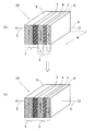
図1は本発明のスピン注入デバイスの概念図であり、(a)はSyAFのスピンが下向きの状態、(b)はスピン注入によりSyAFのスピンが上向きになった状態を示す概念図である。
Hereinafter, the present invention will be described in detail based on embodiments shown in the drawings. The same reference numerals are used for the same or corresponding members in each drawing.
1A and 1B are conceptual diagrams of a spin injection device of the present invention, in which FIG. 1A is a conceptual diagram showing a state in which the spin of SyAF is directed downward, and FIG. 1B is a conceptual diagram showing a state in which the spin of SyAF is directed upward by spin injection.
図1に示すように、本発明のスピン注入デバイス10は、スピン偏極部9と注入接合部7とを有するスピン注入部1と、反強磁性結合する非磁性層2を介して第1の磁性層4と第2の磁性層6とが三層構造を形成するSyAF3とを備え、これらが積層構造を形成する。
まず、本発明に係るSyAF3について説明する。
強磁性体が単層膜の磁化反転に必要な磁場Hswは、一軸磁気異方性Ku、飽和磁化Ms,膜厚t、幅wを用いて一般に次の式(2)で与えられる。
As shown in FIG. 1, a
First, SyAF3 according to the present invention will be described.
The magnetic field Hsw required for the magnetization reversal of the ferromagnetic single layer film is generally given by the following equation (2) using the uniaxial magnetic anisotropy Ku, the saturation magnetization Ms, the film thickness t, and the width w.
Hsw=2Ku/Ms+C(k)tMs/w (2)
ここで、第1項は磁気異方性による項、第2項は反磁界による項である。
Hsw = 2Ku / Ms + C (k) tMs / w (2)
Here, the first term is a term due to magnetic anisotropy, and the second term is a term due to a demagnetizing field.
一方、同様に単磁区構造をとる場合、二つの強磁性層の膜厚t1 、t2 、飽和磁化M1 、M2 をもつSyAFの磁化反転磁場は次式(3)で与えられる。 On the other hand, when a single magnetic domain structure is similarly formed, the magnetization reversal magnetic field of SyAF having the thicknesses t 1 and t 2 of the two ferromagnetic layers and the saturation magnetizations M 1 and M 2 is given by the following equation (3).
Hsw=2Ku/ΔM+C(k)(t1 +t2 )ΔM/w (3)
ここで、ΔM=(t1 +t2 )/(M1 t1 −M2 t2 )、wはSyAFの幅である。
Hsw = 2Ku / ΔM + C (k) (t 1 + t 2 ) ΔM / w (3)
Here, ΔM = (t 1 + t 2 ) / (M 1 t 1 −M 2 t 2 ), and w is the width of SyAF.
上記式(2)及び式(3)において、C(k)はアスペクト比kに依存する反磁界係数であり、kが1に近づくほど小さくなり、k=1ではC(k)=0である。ここで、アスペクト比kは、t/wである。したがって、第1の磁性層4の場合にはt1 /wであり、第2の磁性層6の場合には、t2 /wである(図1(a)参照)。
微小な素子の場合、一般に式(2)、式(3)ともに第2項の方が第1項を上回るので、またΔM<Msであるから、wが同じときSyAFの方が磁化反転磁場が小さくなる。一方、C(k)はk=1のときゼロとなるので、磁化反転磁場は式(2)、式(3)の第1項、すなわち磁気異方性によって決定され、素子サイズに依存しなくなる。
しかし、単層膜の場合にはkが少なくとも2以下では多磁区構造となるため、磁化反転磁場は式(2)では与えられず、その値は、より大きくなるとともに素子サイズに依存する。したがって、単層膜の場合にはk≦2の素子は現実的でない。
In the above equations (2) and (3), C (k) is a demagnetizing factor dependent on the aspect ratio k, and decreases as k approaches 1, and C (k) = 0 when k = 1. . Here, the aspect ratio k is t / w. Therefore, in the case of the first
In the case of a small element, since the second term generally exceeds the first term in both Equations (2) and (3), and ΔM <Ms, the magnetization reversal magnetic field of SyAF is smaller than that of SyAF when w is the same. Become smaller. On the other hand, since C (k) becomes zero when k = 1, the magnetization reversal magnetic field is determined by the first term of Expressions (2) and (3), that is, the magnetic anisotropy, and does not depend on the element size. .
However, in the case of a single-layer film, when k is at least 2 or less, a multi-domain structure is formed. Therefore, the magnetization reversal magnetic field is not given by Expression (2), and its value becomes larger and depends on the element size. Therefore, in the case of a single-layer film, an element with k ≦ 2 is not realistic.
ところが本発明者らは、本発明に係るSyAFの場合にはk≦2、特にk=1でも単磁区構造になることを見出した。その結果、本発明に係るSyAFは、より小さな磁化反転磁場を得ることができ、特にk=1の素子では磁化反転磁場は素子サイズに依存しない。本発明はこの発見に基づいており、SyAFにスピン偏極電子を注入することで、より小さな電流密度で磁化反転を実現することができる。特に、k=1の場合にはC(k)がゼロになるため、磁化反転磁場が著しく小さくなる。 However, the present inventors have found that in the case of the SyAF according to the present invention, a single magnetic domain structure is obtained even when k ≦ 2, especially k = 1. As a result, the SyAF according to the present invention can obtain a smaller magnetization reversal magnetic field. In particular, in a device with k = 1, the magnetization reversal magnetic field does not depend on the device size. The present invention is based on this finding, and by injecting spin-polarized electrons into SyAF, magnetization reversal can be realized with a smaller current density. In particular, when k = 1, C (k) becomes zero, so that the magnetization reversal magnetic field becomes extremely small.
このような本発明に係るSyAF3は、図1(a)及び(b)を参照して、非磁性層2を介して第1の磁性層4と第2の磁性層6との二つの磁性層が互いに反平行に磁気結合している三層構造であり、それぞれの膜厚はナノメーターサイズで形成されている。このSyAF3にスピン注入部1の非磁性金属層の注入接合部7を介して強磁性層のスピン偏極部9からスピン注入することで、SyAF3の磁化反転を実現する。
Referring to FIGS. 1A and 1B, the
非磁性層2はこれを介した両磁性層の磁化を反強磁性結合させる物質であり、この反強非磁性層として、ルテニウム(Ru)、イリジウム(Ir)、ロジウム(Rh)が利用可能である。なお、図1(a)中、5及び8は電流を流すための端子を示している。強磁性層及び磁性層は導電体であるので電極との兼用ができるが、電極を別に設けて電流を流してもよい。
The
図1(b)に示すように、本発明に係るSyAF3においては、第1の磁性層4のスピンと第2の磁性層6のスピンとが反平行状態を維持したまま磁気的に結合している。すなわち、第1の磁性層4の磁化と第2の磁性層6の磁化とは、大きさの異なる反平行状態の磁化、つまり大きさの異なる反平行状態のスピンを有している。
第1の磁性層4の厚さをt1 、磁化をM1 とし、第2の磁性層6の厚さをt2 、磁化をM2 とすると、磁化の大きい方の向き(t1 M1 −t2 M2 )を図1中の強磁性層9のスピンを示す矢印に対してSyAFのスピンの向き↑又は↓とすることができる。SyAF3の磁性層4及び磁性層6の反平行磁化の大きさに差異を設けるには、t1 M1 とt2 M2 とが異なるようにすればよい。
As shown in FIG. 1B, in the
Assuming that the thickness of the first
スピン注入部1は強磁性層からなるスピン偏極部9と非磁性導電層からなる注入接合部7とを積層した構造であり、非磁性導電層の注入接合部7はナノメーターサイズである。ここで、ナノメーターサイズとは電子がその運動量とスピンを保存したまま伝導可能な大きさを意味する。つまり、この注入接合部7はスピン保存伝導可能な大きさである。
金属の場合、電子の平均自由行程は1μm以下であり、この1μm以下のサイズの素子では、注入されたスピンは緩和することなく他方に流れ込むことができる。
スピン注入部1の注入接合部7は図2に示すように非磁性絶縁層12であってもよい。この非磁性絶縁層12はトンネル電流が流れるトンネル接合可能な大きさのナノメーターサイズであり、数nmである。
The
In the case of metal, the mean free path of electrons is 1 μm or less, and in an element having a size of 1 μm or less, the injected spin can flow into the other without relaxation.
The
強磁性層からなるスピン偏極部9は強磁性体であるが、伝導を担うフェルミ面でのアップスピン電子とダウンスピン電子の数が異なっており、この強磁性層のスピン偏極部9からスピン偏極した電子が非磁性金属層の注入接合部7に流れ込むようになっている。
Although the spin-
このような本発明に係るスピン注入デバイスでは、1ミリアンペア(mA)以下の非常に小さな電流を流して、膜面内垂直方向に強磁性層のスピン偏極部9から非磁性金属層(又は非磁性絶縁層12)の注入接合部7を介してスピン注入すると、SyAF3の磁性層4のスピンと磁性層6のスピンとが反平行状態を維持したまま磁化反転する。したがって、本発明のスピン注入デバイスでは、より小さな電流密度でスピン注入による磁化反転ができる。これにより電流を流して磁界を印加することなく、微小な電流を流すだけでスピン注入磁化反転ができるので、ロジック、メモリ及びストレージを備えたスピン注入デバイスが実現可能となる。
In such a spin injection device according to the present invention, a very small current of 1 mA or less is passed from the spin-
次に、第2の実施の形態を説明する。図3は本発明のスピン注入デバイスに係る第2の実施形態を示す概略図である。図3を参照すると、この実施形態のものは、スピン偏極部9が反強磁性層21と強磁性層23とを有する構造であり、強磁性層23に反強磁性層21を近接させることで強磁性層23のスピンを固定している。また、注入接合部はスピン保存伝導可能な非磁性金属層25であり、これに代えてトンネル接合可能な絶縁層を用いてもよい。このような構成ではスピン偏極部のスピンを固定してスピン注入し、SyAFの磁化反転ができる。
Next, a second embodiment will be described. FIG. 3 is a schematic view showing a second embodiment according to the spin injection device of the present invention. Referring to FIG. 3, this embodiment has a structure in which the
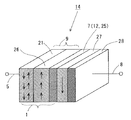
次に、第3の実施の形態を説明する。図4は第3の実施形態のスピン注入デバイスを示す概略図である。図4を参照すると、このスピン注入デバイス14は、反強磁性層21と強磁性固定層26とからなるスピン偏極部9と、強磁性固定層に接して設けられる注入接合部となる非磁性層7と、非磁性層7上に強磁性フリー層27及び非磁性層28からなる二層構造を備えている。
スピン注入部1は、スピン偏極部9と注入接合部7とからなっていて、スピン偏極部9において、強磁性固定層26に反強磁性層21を近接させることで強磁性固定層26のスピンを固定している。
また、注入接合部7はスピン保存伝導可能なCuなどの非磁性金属層25であり、これに代えてトンネル接合可能な絶縁層12を用いてもよい。
Next, a third embodiment will be described. FIG. 4 is a schematic view showing a spin injection device according to the third embodiment. Referring to FIG. 4, the
The
The
第3実施形態のスピン注入デバイス14が図3に示したスピン注入デバイスと異なるのは、SyAF3の代りに強磁性フリー層27及び非磁性層28を備えていることである。非磁性層28は強磁性フリー層27との界面において、多数(マジョリティ)スピンを反射させ、少数(マイノリティ)スピンを透過させるために設けている。したがって、非磁性層28の膜厚は、少数スピンがスピンを保存したまま動ける距離、すなわちスピン拡散長以内にしておけばよい。
ここで、強磁性フリー層27としてはCoまたはCo合金を用いることができる。非磁性層28としては、Ru、Ir、Rhが利用可能であり、特にRuを用いるのが好適である。また、Ruのスピン拡散長は14nmであることが知られており、Ruの膜厚は0.1nm〜20nmとすればよい。以下、強磁性フリー層27にCoまたはCo合金を用い、非磁性層28にRuを用いるとして説明する。
The
Here, as the ferromagnetic
図5は上記第3の実施形態のスピン注入デバイス14の磁化反転を説明する模式図である。図5において、強磁性固定層26から強磁性フリー層27へ電子が注入されると、多数スピン電子17が強磁性フリー層27の磁化を強磁性固定層26の磁化に揃うようにトルク18を与える。この際、CoまたはCo合金27とRu28の界面においては、多数スピン電子が強く散乱(反射)され、少数スピン電子はあまり散乱を受けない(透過)ことが知られている。
したがって、図5に示すように、CoまたはCo合金27とRu28の界面において反射された多数スピン電子19は、CoまたはCo合金27の膜厚がスピン伝導が保存される程度に薄ければ、この反射された多数スピン電子19も強磁性フリー層27に同様のトルク18’を与える。これにより、実質的に強磁性フリー層27のトルクが増大し、強磁性固定層26の磁化と同じ向きになる。
FIG. 5 is a schematic diagram illustrating the magnetization reversal of the
Therefore, as shown in FIG. 5, the majority spin electrons 19 reflected at the interface between the Co or
一方、電流の向きを逆に与え、Ru層28からCoまたはCo合金27側に電子を注入すると、多数スピン電子はCoまたはCo合金27とRu28の界面で反射され、少数スピン電子だけがCoまたはCo合金からなる強磁性フリー層27に注入され、この少数スピン電子が強磁性フリー層27のスピンにトルクを与え、そのスピンを同じ向き、つまり下向きにそろえようとする。これにより、強磁性フリー層27の少数スピン電子によるトルクが増大し、強磁性フリー層27のスピンは強磁性固定層26の磁化と反平行になる。 このように本発明のスピン注入デバイス14によれば、非磁性層28の挿入により、スピン偏極部9のスピンを固定してスピン注入し、強磁性フリー層27の磁化反転を従来のスピン注入磁化反転よりも低い電流密度で行うことができる。
On the other hand, when the direction of the current is reversed and electrons are injected from the
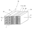
さらに、第4の実施の形態のスピン注入デバイスを図6を参照して説明する。この実施形態のスピン注入デバイス16が図4に示したスピン注入デバイス14と異なるのは、非磁性層28上にさらに強磁性固定層29を備えている点にある。他の構成は図4に示すスピン注入デバイス14と同じであるので説明は省略する。
ここで、強磁性フリー層27及び強磁性固定層29は、SyAF3のようにそれらの磁化が反平行とならないように、かつ、スピン保存伝導が生起するように非磁性層28の膜厚を決めればよい。したがって、強磁性フリー層27及び強磁性固定層29としてCoまたはCo合金を、非磁性層28としてRuを用いた場合には、Ruの厚さは、SyAF3とならないように、2〜20nm程度とすればよい。
Further, a spin injection device according to a fourth embodiment will be described with reference to FIG. The
Here, the thickness of the
次に、上記第4の実施形態のスピン注入デバイス16の動作について説明する。
図6において、強磁性固定層26から強磁性フリー層27へ電子が注入された場合には、第3実施形態のスピン注入デバイス14と同様に、CoまたはCo合金からなる強磁性フリー層27の磁化は、強磁性固定層26の磁化と同じ向きになる。
Next, the operation of the
In FIG. 6, when electrons are injected from the ferromagnetic fixed
一方、電流の向きを逆に与えた場合を、図7を参照して説明する。
図7は、第4実施形態のスピン注入デバイス16の磁化反転を説明する模式図である。図7において、強磁性固定層29から強磁性フリー層27へ電子が注入されると、多数スピン電子37が強磁性固定層29とRu層28の界面で強く反射され、強磁性フリー層27へは到達しない。この際、CoまたはCo合金27の膜厚がスピン伝導が保存される程度に薄ければ、少数スピン電子39は散乱を受けないので強磁性フリー層27に到達し、強磁性フリー層27のスピンを揃えるようにトルク38を与える。したがって、強磁性フリー層27の磁化は、強磁性固定層26とは反平行となる。これにより、Ru層28がない場合よりも、多数スピン電子37が強磁性フリー層27に到達しなくなり、より小さい電流密度で磁化反転ができる。
このように、本実施形態のスピン注入デバイス16によれば、スピン偏極部9のスピンを固定してスピン注入し、SyAF3の代りに用いる強磁性フリー層27、非磁性層28,強磁性固定層29において、強磁性フリー層27の磁化反転を低電流密度で行うことができる。
On the other hand, a case where the direction of the current is given in reverse will be described with reference to FIG.
FIG. 7 is a schematic diagram illustrating the magnetization reversal of the
As described above, according to the
上記スピン注入デバイスにおいて、強磁性フリー層27の磁化反転が起こるとき、強磁性固定層26の磁化と平行又は反平行となることにより、反強磁性層21と強磁性固定層26とCuなどの非磁性金属層25からなる注入接合部7と強磁性フリー層27とを含む層構造は、CPP型の巨大磁気抵抗効果素子と同じように、巨大磁気抵抗効果が生じる。 また、非磁性層7がトンネル接合可能な絶縁層12である場合に強磁性フリー層27の磁化反転が起こると、反強磁性層21と強磁性固定層26とトンネル接合可能な絶縁層12と強磁性フリー層27とを含む層構造は、CPP型のトンネル磁気抵抗効果素子と同じように、トンネル磁気抵抗効果が生じる。
In the spin injection device, when the magnetization reversal of the ferromagnetic
次に、本発明のスピン注入磁気装置について説明する。図8は本発明のスピン注入磁気装置の概略図である。スピン注入磁気装置30は、フリー層としたSyAF3と、強磁性層32及び反強磁性層34からなる固定層31とが、絶縁層33でトンネル接合した強磁性スピントンネル接合(MTJ)素子36であって、このMTJ素子36に強磁性層であるフリー層を磁化反転させるためのスピン注入部1を備えている。スピン注入部1は注入接合部をトンネル接合可能な絶縁層12にしたものである。
Next, the spin injection magnetic device of the present invention will be described. FIG. 8 is a schematic view of the spin injection magnetic device of the present invention. The spin injection
このようなスピン注入磁気装置では、強磁性層23から絶縁層12を介してSyAF3にスピン注入すると、このSyAF3の磁化が反転する。このSyAF3であるフリー層の磁化が↑又は↓に反転して固定層31の磁化と平行又は反平行となることにより、トンネル磁気抵抗(TMR)効果が出現する。したがって、このスピン注入磁気装置30は、より小さな電流密度でスピン注入によるフリー層の磁化反転を起こすことができる。
In such a spin injection magnetic device, when spin injection is performed from the
上記スピン注入磁気装置において、SyAF3を、図4に示した第3実施形態のスピン注入デバイス14の強磁性フリー層27及び強磁性自由層上に設ける非磁性層28からなる二層構造に代えた構成としてもよい。
また、上記スピン注入磁気装置において、SyAF3を、図6に示した第4実施形態のスピン注入デバイス16の強磁性フリー層27、非磁性層28、非磁性層上に設ける強磁性層29からなる三層構造に代えた構成としてもよい。
In the spin injection magnetic device, SyAF3 is replaced with a two-layer structure including the ferromagnetic
In the spin injection magnetic device, the
このように本発明のスピン注入磁気装置は、超ギガビット大容量・高速・不揮発メモリに利用可能になる。 Thus, the spin injection magnetic device of the present invention can be used for a super-gigabit large-capacity, high-speed, nonvolatile memory.
このようなスピン注入磁気装置では、フリー層のSyAFをトンネル接合可能な絶縁膜で挟み又は覆って、このSyAFに対応する部分のスピン注入部でワード線として結合して微細加工し、固定層側の強磁性層にビット線を連結して微細加工することにより、MRAMやスピン注入磁気メモリ装置の基本構造とすることができる。
ここで、フリー層はSyAFの他には、強磁性フリー層27及び非磁性層28からなる二層構造または強磁性フリー層27、非磁性層28、非磁性層上に設ける強磁性層29からなる三層構造を用いることができる。
In such a spin injection magnetic device, the free layer SyAF is sandwiched or covered with an insulating film capable of tunnel junction, and the spin injection portion corresponding to the SyAF is coupled as a word line and finely processed to form a fixed layer side. By connecting a bit line to the ferromagnetic layer and performing fine processing, a basic structure of an MRAM or a spin injection magnetic memory device can be obtained.
Here, the free layer is formed of a two-layer structure including a ferromagnetic
次に、本発明のスピン注入デバイスやスピン注入磁気装置に用いることができる磁性薄膜について説明する。
図9は、本発明に用いることができる磁性薄膜の断面図である。図9に示すように、磁性薄膜41は、基板42上に、室温においてCo2 Fex Cr1-x Al薄膜43を配設している。ここで、0≦x≦1である。
Co2 Fex Cr1-x Al薄膜43は、室温で強磁性であり、電気抵抗率が190μΩ・cm程度であり、かつ、基板を加熱することなくL21 ,B2,A2構造の何れか一つの構造を有している。
さらに、上記Co2 Fex Cr1-x Al薄膜43を配設した基板を加熱することで、スピン分極率の大きいL21 構造のCo2 Fex Cr1-x Al薄膜43が得られやすい。ここで、基板42上のCo2 Fex Cr1-x Al薄膜43の膜厚は、1nm以上1μm以下であればよい。
Next, a magnetic thin film that can be used in the spin injection device and the spin injection magnetic device of the present invention will be described.
FIG. 9 is a sectional view of a magnetic thin film that can be used in the present invention. As shown in FIG. 9, a magnetic
The Co 2 Fe x Cr 1-x Al
Further, by heating the substrate on which the Co 2 Fe x Cr 1-x Al
図10は、本発明に用い得る磁性薄膜の変形例の断面図である。本発明に用いる磁性薄膜45は、図9の磁性薄膜41の構造において、さらに基板42とCo2 Fex Cr1-x Al(ここで、0≦x≦1)薄膜43との間にバッファー層44が挿入されている。バッファー層44を挿入することで、基板41上のCo2 Fex Cr1-x Al(ここで、0≦x≦1)薄膜43の結晶性をさらによくすることができる。
FIG. 10 is a sectional view of a modification of the magnetic thin film that can be used in the present invention. The magnetic
上記磁性薄膜41,45に用いる基板42は、熱酸化Si、ガラスなどの多結晶、MgO、Al2 O3 、GaAsなどの単結晶を用いることができる。また、バッファー層44としては、Al,Cu,Cr,Fe,Nb,Ni,Ta,NiFeなどを用いることができる。
上記Co2 Fex Cr1-x Al(ここで、0≦x≦1)薄膜43の膜厚は、1nm以上で1μm以下であればよい。この膜厚が1nm未満では実質的に後述するL21 ,B2,A2構造の何れか一つの構造を得るのが困難になり、そして、この膜厚が1μmを超えるとスピン注入デバイスとしての応用が困難になり好ましくない。
As the
The thickness of the Co 2 Fe x Cr 1-x Al (here, 0 ≦ x ≦ 1)
次に、上記構成の磁性薄膜の作用を説明する。
図11は、磁性薄膜に用いるCo2 Fex Cr1-x Al(ここで、0≦x≦1)の構造を模式的に説明する図である。図に示す構造は、bcc(体心立方格子)の慣用的単位胞の8倍(格子定数で2倍)の構造を示している。
Co2 Fex Cr1-x AlのL21 構造においては、図9のIの位置にFeとCrが組成比としてFex Cr1-x (ここで、0≦x≦1)となるように配置され、IIの位置にAl、III とIVの位置にCoが配置される。
また、Co2 Fex Cr1-x AlのB2構造においては、図9のIの位置とIIの位置に、FeとCrとAlが不規則に配列される構造となる。この際、FeとCrの組成比は、Fex Cr1-x (ここで、0≦x≦1)となるように配置される。
さらに、Co2 Fex Cr1-x AlのA2構造においては、Co,Fe,CrおよびAlが不規則に置換した構造となる。この際、FeとCrの組成比は、Fex Cr1-x (ここで、0≦x≦1)となるように配置される。
Next, the operation of the magnetic thin film having the above configuration will be described.
FIG. 11 is a diagram schematically illustrating the structure of Co 2 F x Cr 1-x Al (here, 0 ≦ x ≦ 1) used for the magnetic thin film. The structure shown in the figure shows a structure that is eight times (double the lattice constant) the conventional unit cell of bcc (body-centered cubic lattice).
In the L2 1 structure of Co 2 Fe x Cr 1-x Al, the composition ratio of Fe and Cr is F x Cr 1-x (where 0 ≦ x ≦ 1) at the position I in FIG. Al is placed at the position II, and Co is placed at the positions III and IV.
Further, the B2 structure of Co 2 Fe x Cr 1-x Al has a structure in which Fe, Cr and Al are irregularly arranged at positions I and II in FIG. In this case, the composition ratio of Fe and Cr is set so as to satisfy FexCr1 -x (where 0≤x≤1).
Further, the A2 structure of Co 2 Fe x Cr 1-x Al has a structure in which Co, Fe, Cr and Al are irregularly substituted. In this case, the composition ratio of Fe and Cr is set so as to satisfy FexCr1 -x (where 0≤x≤1).
次に、上記構成の磁性薄膜41,45の磁気的性質を説明する。
上記構成のCo2 Fex Cr1-x Al(ここで、0≦x≦1)薄膜43は、室温で強磁性であり、かつ、基板を加熱することなくL21 ,B2,A2構造の何れか一つの構造のCo2 Fex Cr1-x Al薄膜が得られる。
さらに、上記構成のCo2 Fex Cr1-x Al薄膜43(ここで、0≦x≦1)は膜厚が数nm程度の非常に薄い膜においてもL21 ,B2,A2構造の何れか一つの構造が得られる。
ここで、Co2 Fex Cr1-x Al(ここで、0≦x≦1)薄膜のB2構造は、従来得られていない特異な物質である。B2構造は、L21 構造と類似しているが、異なるのはL21 構造では、Cr(Fe)とAl原子が規則的に配置しているのに対し、B2構造は、不規則に配列していることである。また、A2構造は、Co,Fe,CrおよびAlが不規則に置換した構造となる。これらの違いはX線回折で測定することができる。
上記Co2 Fex Cr1-x Al薄膜43の組成xにおいて、0≦x≦0.8の範囲内では、特に、基板を加熱することなくL21 ,B2の何れか一つの構造を得ることができる。また、0.8≦x≦1.0では、A2構造が得られる。
また、組成xにおいて、0≦x≦1の範囲内で、加熱した基板上のCo2 Fex Cr1-x Al薄膜の成膜や、基板を加熱することなく成膜した後の熱処理などにより、L21 またはB2構造が得られる。
Next, the magnetic properties of the magnetic
The Co 2 Fe x Cr 1-x Al (here, 0 ≦ x ≦ 1)
Further, the Co 2 Fe x Cr 1-x Al thin film 43 (here, 0 ≦ x ≦ 1) having any one of the L2 1 , B2, and A2 structures even in a very thin film having a thickness of about several nm. One structure is obtained.
Here, the B2 structure of the Co 2 Fe x Cr 1-x Al (here, 0 ≦ x ≦ 1) thin film is a unique substance that has not been obtained conventionally. The B2 structure is similar to the L2 1 structure, except that in the L2 1 structure, Cr (Fe) and Al atoms are regularly arranged, whereas the B2 structure is irregularly arranged. That is. The A2 structure is a structure in which Co, Fe, Cr and Al are irregularly substituted. These differences can be measured by X-ray diffraction.
In composition x of the Co 2 Fe x Cr 1-x Al
Further, in the composition x, within a range of 0 ≦ x ≦ 1, a Co 2 Fe x Cr 1-x Al thin film is formed on a heated substrate, or a heat treatment is performed after forming the film without heating the substrate. , L2 1 or B2 structures are obtained.
上記構成の磁性薄膜41,45がハーフメタルであることを実験的に明らかにすることは難しいが、定性的にはトンネル接合を有するトンネル磁気抵抗効果素子を作製し、それが100%を超えるような非常に大きなTMRを示す場合にはハーフメタル的と考えることができる。
絶縁膜の片側にCo2 Fex Cr1-x Al(0≦x≦1)薄膜43を強磁性層として用い、絶縁膜の他方の強磁性層にスピン分極率が0.5のCoFe合金を用いてトンネル磁気抵抗効果素子を作製した結果、100%を超える大きなTMRを得た。
It is difficult to experimentally clarify that the magnetic
A Co 2 Fe x Cr 1-x Al (0 ≦ x ≦ 1)
これは(1)式から考えて、Co2 Fex Cr1-x Al(0≦x≦1)薄膜43が、P=0.7以上のスピン分極率をもつことを示している。このような大きなTMRを得ることができたのは、Co2 Fex Cr1-x Al(0≦x≦1)薄膜3が大きなスピン分極率を有していることのほかに、室温でL21 ,B2,A2構造の何れか一つの構造が得られるという発見に基づく。
これにより、磁性薄膜41,45によれば、基板を加熱する必要がなく、Co2 Fex Cr1-x Al(0≦x≦1)薄膜43が1nm以上の厚みで強磁性特性を得ることができる。これは、表面が酸化したり表面粗さが増大したりすることがなく、トンネル接合の界面をクリーンでかつシャープに作製することができたことにより、大きなスピン分極率とトンネル磁気抵抗効果素子において大きなTMRを得ることができるものと推察される。
This indicates that the Co 2 F x Cr 1-x Al (0 ≦ x ≦ 1)
Thus, according to the magnetic
上記磁性薄膜41,45は、本発明のスピン注入デバイスに用いるSyAF3の第1及び第2の磁性層、あるいは、スピン注入部の強磁性層9などに用いることができる。また、磁性薄膜41,45は、本発明のスピン注入デバイス14,16に用いる反強磁性層21と強磁性固定層26とCuなどの非磁性金属層25と強磁性フリー層28とからなる層構造であるCPP型巨大磁気抵抗効果素子構造や、反強磁性層21と強磁性固定層26とトンネル接合可能な絶縁層12と強磁性フリー層28とからなる層構造であるトンネル磁気抵抗効果素子構造に用いることができる。さらに、本発明のスピン注入磁気装置に用いるMTJ素子あるいはトンネル磁気抵抗効果素子の強磁性層に用いることができる。
The magnetic
次に、実施例1について説明する。実施例1は、図4に示すスピン注入デバイス14の構造に相当するものである。
マグネトロンスパッタ法を用いて、熱酸化Si基板上にTa(2nm)/Cu(20nm)/IrMn(10nm)/Co90Fe10(5nm)/Cu(6nm)/Co90Fe10(2.5nm)/Ru(0.45nm)/Cu(5nm)/Ta(2nm)を順にスパッタした。
ここで、熱酸化Si基板上及びその最上層のTaとCuからなる層は電極となる層である。IrMn層及びCo90Fe10層は、それぞれ、反強磁性層21及び強磁性固定層26からなるスピン偏極部9である。Cuは注入接合部7である。Co合金のCo90Fe10及びRuは非磁性層7のCu上に配設した強磁性フリー層27及び非磁性層28である。
次に、この膜を電子ビームリソグラフィとArイオンミリングを用いて微細加工し、図4に示すようなスピン注入デバイス14を作製した。素子サイズは300×100nm2 である。
Next, a first embodiment will be described. Example 1 corresponds to the structure of the
Using a magnetron sputtering method, Ta (2 nm) / Cu (20 nm) / IrMn (10 nm) / Co 90 Fe 10 (5 nm) / Cu (6 nm) / Co 90 Fe 10 (2.5 nm) are formed on a thermally oxidized Si substrate. / Ru (0.45 nm) / Cu (5 nm) / Ta (2 nm) were sequentially sputtered.
Here, the layer made of Ta and Cu on the thermally oxidized Si substrate and the uppermost layer is a layer to be an electrode. The IrMn layer and the Co 90 Fe 10 layer are the spin-
Next, this film was finely processed by using electron beam lithography and Ar ion milling to produce a
図12は室温における実施例1のスピン注入デバイス14のスピン注入磁化反転を示す図である。図において、横軸は、強磁性フリー層27から強磁性固定層26への電流を正方向としたときのスピン注入デバイス電流(mA)を示し、縦軸はそのときの抵抗(Ω)を示している。最初に、スピン注入デバイス14に外部磁界Hを印加して、反平行状態、すなわち高抵抗の初期状態とした。このときの外部磁界Hは、50Oe(エルステッド)である(図12のA参照)。
図から明らかなように、Aに示す微小電流の高抵抗状態から、正の向きにBで示す約5mAまで電流を流していくと抵抗が急激に減少し、磁化反転していることが分かる。さらに、電流を20mAまで増加してもこの低抵抗状態が保持されていることが分かる(図12のB〜C参照)。
次に、電流を減少し、さらに負の方向に印加すると、約−7.5mAまでは低抵抗を保持する(図12のC〜D参照)。それ以上の負電流を印加すると再び高抵抗状態になり、磁化反転することが分かる(図12のE〜F参照)。この磁化反転に要する電流密度は、2.4×10⁷ A/cm2 であり、後述する比較例に比べ約1/10となった。また、磁気抵抗(MR)は図示するように0.97%であり、後述する比較例のスピン反転構造における磁気抵抗と同じ値が得られた。
これにより、実施例1のスピン注入デバイス14においては、それに流す電流の向きを変えて、強磁性フリー層27の磁化反転を発現させることで、その抵抗を変化させることができる。
FIG. 12 is a diagram showing the spin injection magnetization reversal of the
As is clear from the figure, when a current is passed from the high resistance state of the small current indicated by A to about 5 mA indicated by B in the positive direction, the resistance sharply decreases and the magnetization is reversed. Further, it can be seen that this low resistance state is maintained even when the current is increased to 20 mA (see BC in FIG. 12).
Next, when the current is reduced and further applied in the negative direction, the resistance is kept low until about -7.5 mA (see C to D in FIG. 12). It can be seen that when a negative current larger than that is applied, the state again becomes a high resistance state and the magnetization is reversed (see EF in FIG. 12). The current density required for this magnetization reversal was 2.4 × 10 7 A / cm 2 , which was about 1/10 as compared with a comparative example described later. The magnetoresistance (MR) was 0.97% as shown in the drawing, and the same value as the magnetoresistance in the spin inversion structure of the comparative example described later was obtained.
Thus, in the
次に、実施例2について説明する。実施例2は、図6に示すスピン注入デバイス16の構造に相当するものである。
マグネトロンスパッタ法を用いて、熱酸化Si基板上にTa(2nm)/Cu(20nm)/IrMn(10nm)/Co90Fe10(5nm)/Cu(6nm)/Co90Fe10(2.5nm)/Ru(6nm)/Co90Fe10(5nm)/Cu(5nm)/Ta(2nm)を順にスパッタした。
ここで、熱酸化Si基板上及びその最上層のTaとCuからなる層は電極となる層である。IrMn層及びCo90Fe10層は、それぞれ、反強磁性層21と強磁性固定層26とからなるスピン偏極部9である。Cuは注入接合部7である。Co合金のCo90Fe10,Ru,Co90Fe10は、それぞれ、非磁性層7のCu上に配設した強磁性フリー層27,非磁性層28,強磁性層29である。
Next, a second embodiment will be described. The second embodiment corresponds to the structure of the
Using a magnetron sputtering method, Ta (2 nm) / Cu (20 nm) / IrMn (10 nm) / Co 90 Fe 10 (5 nm) / Cu (6 nm) / Co 90 Fe 10 (2.5 nm) are formed on a thermally oxidized Si substrate. / Ru (6 nm) / Co 90 Fe 10 (5 nm) / Cu (5 nm) / Ta (2 nm) were sequentially sputtered.
Here, the layer made of Ta and Cu on the thermally oxidized Si substrate and the uppermost layer is a layer to be an electrode. The IrMn layer and the Co 90 Fe 10 layer are the
実施例2のスピン注入デバイス16が実施例1のスピン注入デバイス14と異なるのは、Co90Fe1027上のRu28の膜厚を0.45nmから6nmと厚くしたことと、強磁性層29として膜厚5nmのCo90Fe10層29を設けたことである。
次に、実施例1と同じ方法で、素子サイズが100×100nm2 のスピン注入デバイス16を作製した。
The
Next, a
図13は、室温における実施例2のスピン注入デバイス16のスピン注入磁化反転を示す図である。図において、横軸は、強磁性フリー層27から強磁性固定層26への電流を正方向としたときのスピン注入デバイス電流(mA)を示し、縦軸はそのときの抵抗(Ω)を示している。高抵抗の初期状態とするために印加した外部磁界Hは、150Oeである。
図から明らかなように、実施例2のスピン注入デバイス16は、実施例1のスピン注入デバイス14と同様に電流が±約0.2mAで抵抗が変化し、磁化反転が発現することが分かる。この磁化反転に要する電流密度は1×10⁶ A/cm2 となった。この値は、実施例1の約1/24となり、後述する比較例の約1/200である。また、磁気抵抗は約1%であり、後述する比較例の磁気抵抗(MR)と同じ値が得られた。このように、非磁性層28であるRuの膜厚を6nmとすることにより、磁化反転に要する電流密度を低くすることができた。
FIG. 13 is a diagram illustrating the spin transfer magnetization reversal of the
As is clear from the drawing, the resistance of the
次に、実施例3について説明する。実施例3は、図8に相当する構造に対するものである。
マグネトロンスパッタ法を用いて、熱酸化Si基板上にCu(100nm)/NiFe(3nm)/IrMn(10nm)/Co90Fe10(3nm)をまず作製した。次にこの膜の上に厚さ3nmのSiO2 をスパッタし、さらにその上にCo90Fe10(1nm)/Ru(0.45nm)/Co90Fe10(1.5nm)/SiO2 (3nm)をスパッタした。次に、上部磁性層として、Co90Fe10(10nm)/IrMn(10nm)/Ta(5nm)を成膜した。
Next, a third embodiment will be described. Example 3 is directed to a structure corresponding to FIG.
First, Cu (100 nm) / NiFe (3 nm) / IrMn (10 nm) / Co 90 Fe 10 (3 nm) were first formed on a thermally oxidized Si substrate using a magnetron sputtering method. Next, a SiO 2 film having a thickness of 3 nm is sputtered on the film, and Co 90 Fe 10 (1 nm) / Ru (0.45 nm) / Co 90 Fe 10 (1.5 nm) / SiO 2 (3 nm ) Was sputtered. Next, a film of Co 90 Fe 10 (10 nm) / IrMn (10 nm) / Ta (5 nm) was formed as an upper magnetic layer.
この膜の断面を透過型電子顕微鏡を用いて調べた結果、Co90Fe10(1nm)/Ru(0.45nm)/Co90Fe10(1.5nm)はSiO2 中に一層だけ層状に分散した粒子状をしており、SiO2 を絶縁マトリックスとする二重トンネル構造であることがわかった。この構造に対して、上下のCuとTa膜間に電圧を印加して電流を流し、そのときの抵抗を電流を変化させて室温で測定した結果、約0.1mAで抵抗の飛びを観測した。これはCo90Fe10(1nm)/Ru(0.45nm)/Co90Fe10(1.5nm)SyAFの磁化反転に伴うTMRの発現によるものであり、スピン注入によって磁化反転したことを意味している。 As a result of examining the cross section of this film using a transmission electron microscope, it was found that Co 90 Fe 10 (1 nm) / Ru (0.45 nm) / Co 90 Fe 10 (1.5 nm) was dispersed in a single layer in SiO 2. It was found that the particles had a double tunnel structure using SiO 2 as an insulating matrix. With respect to this structure, a voltage was applied between the upper and lower Cu and Ta films to flow a current, and the resistance at that time was measured at room temperature while changing the current. As a result, a jump in resistance was observed at about 0.1 mA. . This is due to the appearance of TMR accompanying the magnetization reversal of Co 90 Fe 10 (1 nm) / Ru (0.45 nm) / Co 90 Fe 10 (1.5 nm) SyAF, which means that the magnetization was reversed by spin injection. ing.
(比較例)
次に、比較例について説明する。
比較例は、図15に示す従来のスピン反転法に用いる三層構造の第1の強磁性層61上にさらに反強磁性層を設けた構造である。すなわち、実施例1のスピン注入デバイス14においてRu層のない構造として、熱酸化Si基板上にTa(2nm)/Cu(20nm)/IrMn(10nm)/Co90Fe10(5nm)/Cu(6nm)/Co90Fe10(2.5nm)/Cu(5nm)/Ta(2nm)を順にスパッタした。次に、実施例1と同じ方法で、素子サイズを300×100nm2 とした。
(Comparative example)
Next, a comparative example will be described.
The comparative example has a structure in which an antiferromagnetic layer is further provided on the first
図14は、室温における比較例の(a)磁気抵抗曲線と、(b)スピン注入磁化反転を示す図である。図14(a)において、横軸は印加する磁界(Oe)であり、縦軸は抵抗(Ω)である。素子電流は1mAである。磁気抵抗は、外部磁界が0(図14(a)のG参照)からスイープして測定した。
図14(a)から明らかなように、比較例の磁気抵抗(MR)は1.1%と、従来報告された値と同じ値であることが分かる。また、図14(b)において、横軸は、第2の強磁性層63から第1の強磁性層61へ電流を流した場合を正方向とした電流(mA)を示し、縦軸はそのときの抵抗(Ω)を示している。図14(b)から明らかなように、電流がほぼ0から矢印の方向に電流を正から負にすることで、実施例1と同様に磁化反転が発現した(図14(b)のK〜L参照)。磁気抵抗は0.98%で、磁化反転に要する電流密度は2.4×10⁸ A/cm2 であった。
FIG. 14 is a diagram showing (a) a magnetoresistance curve and (b) spin transfer magnetization reversal of a comparative example at room temperature. In FIG. 14A, the horizontal axis is the applied magnetic field (Oe), and the vertical axis is the resistance (Ω). The device current is 1 mA. The magnetic resistance was measured by sweeping from an external magnetic field of 0 (see G in FIG. 14A).
As is apparent from FIG. 14A, the magnetoresistance (MR) of the comparative example is 1.1%, which is the same value as the value reported conventionally. In FIG. 14B, the horizontal axis represents the current (mA) when the current flows from the second
次に、実施例及び比較例の比較について説明する。
実施例においては、磁化反転に要する電流密度が、比較例よりも低下した。特に、実施例2のようにRu層28の膜厚を2〜20nmの範囲内とすれば、磁化反転に要する電流密度が1×10⁶ A/cm2 となり、従来例の1/10の値に低減化できることが分かった。
Next, comparison between the example and the comparative example will be described.
In the example, the current density required for the magnetization reversal was lower than in the comparative example. In particular, when the thickness of the
本発明はこれら実施例に限定されるものではなく、特許請求の範囲に記載した発明の範囲内で種々の変形が可能であり、それらも本発明の範囲内に含まれることはいうまでもない。 The present invention is not limited to these examples, and various modifications are possible within the scope of the invention described in the claims, and it goes without saying that they are also included in the scope of the present invention. .
1: スピン注入部
2: 非磁性層
3: SyAF
4: 第1の磁性層
6: 第2の磁性層
7: 注入接合部
9: スピン偏極部
10,14,16: スピン注入デバイス
12: 非磁性絶縁層
17,37: 多数スピン電子
18,18’,38: トルク
19: CoまたはCo合金とRuの界面において反射された多数スピン電子
21: 反強磁性層
23: 強磁性層
25: 非磁性金属層
27: 強磁性自由層
28: 強磁性自由層上に設ける非磁性層
29: 非磁性層上に設ける強磁性層
30: スピン注入磁気装置
31: 固定層
32: 強磁性層
33: 絶縁層
36: MTJ素子
39: 少数スピン電子
41,45: 磁性薄膜
42: 基板
43: Co2 Fex Cr1-x Al薄膜
44: バッファー層
1: spin injection part 2: non-magnetic layer 3: SyAF
4: First magnetic layer 6: Second magnetic layer 7: Injection junction 9:
Claims (20)
非磁性層を介して磁気的に反平行に結合した磁化の大きさが異なる第1の磁性層及び第2の磁性層を有するSyAFと、を備え、
上記SyAFと上記注入接合部とが接合しており、
上記スピン注入部からスピン偏極電子を注入し上記第1の磁性層及び上記第2の磁性層の磁化が反平行状態を維持したまま磁化反転する、スピン注入デバイス。 A spin injection unit having a spin polarization unit and an injection junction,
A SyAF having a first magnetic layer and a second magnetic layer having different magnitudes of magnetization magnetically coupled antiparallel via a nonmagnetic layer,
The SyAF and the injection joint are joined,
A spin injection device in which spin-polarized electrons are injected from the spin injection section and the magnetization of the first magnetic layer and the second magnetic layer is reversed while maintaining the antiparallel state.
上記フリー層と絶縁層を介してトンネル接合した強磁性固定層と、を備え、
上記強磁性固定層と上記フリー層とが強磁性スピントンネル接合した、スピン注入磁気装置。 A first magnetic layer and a second magnetic layer having different magnetization magnitudes that are magnetically coupled antiparallel via a nonmagnetic layer, and the magnetizations of the first magnetic layer and the second magnetic layer are A free layer capable of reversing magnetization while maintaining an antiparallel state,
A ferromagnetic fixed layer tunnel-joined via the free layer and an insulating layer,
A spin injection magnetic device, wherein the ferromagnetic pinned layer and the free layer have a ferromagnetic spin tunnel junction.
上記非磁性層が絶縁体または導電体からなり、上記強磁性フリー層の表面に非磁性層が設けられ、上記スピン注入デバイスの膜面垂直方向に電流を流し、上記強磁性フリー層の磁化を反転させることを特徴とする、スピン注入デバイス。 In a spin injection device including a spin injection portion including a spin polarization portion including a ferromagnetic fixed layer and an injection junction of a nonmagnetic layer, and a ferromagnetic free layer provided in contact with the spin injection portion,
The non-magnetic layer is made of an insulator or a conductor, a non-magnetic layer is provided on the surface of the ferromagnetic free layer, and a current flows in a direction perpendicular to the film surface of the spin injection device to change the magnetization of the ferromagnetic free layer. A spin injection device characterized by being inverted.
上記非磁性層が絶縁体または導電体からなり、
上記強磁性フリー層の表面に非磁性層と強磁性層とが設けられ、
上記スピン注入デバイスの膜面垂直方向に電流を流し、上記強磁性フリー層の磁化を反転させることを特徴とする、スピン注入デバイス。 A spin injection device including: a spin injection unit including a spin polarization unit including a ferromagnetic fixed layer and an injection junction of a nonmagnetic layer; and a ferromagnetic free layer provided in contact with the spin injection unit.
The non-magnetic layer is made of an insulator or a conductor,
A nonmagnetic layer and a ferromagnetic layer are provided on the surface of the ferromagnetic free layer,
A spin injection device, characterized in that a current flows in a direction perpendicular to the film surface of the spin injection device to reverse the magnetization of the ferromagnetic free layer.
Priority Applications (8)
| Application Number | Priority Date | Filing Date | Title |
|---|---|---|---|
| JP2003410966A JP4873338B2 (en) | 2002-12-13 | 2003-12-09 | Spin injection device and magnetic apparatus using the same |
| EP03778828A EP1571713A4 (en) | 2002-12-13 | 2003-12-11 | Spin injection device, magnetic device using the same, magnetic thin film used in the same |
| PCT/JP2003/015888 WO2004055906A1 (en) | 2002-12-13 | 2003-12-11 | Spin injection device, magnetic device using the same, magnetic thin film used in the same |
| US10/538,689 US7675129B2 (en) | 2002-12-13 | 2003-12-11 | Spin injection device, magnetic device using the same, magnetic thin film used in the same |
| KR1020057010827A KR100663857B1 (en) | 2002-12-13 | 2003-12-11 | Spin injection device, magnetic device using the same, magnetic thin film used in the same |
| EP10008650A EP2249356A1 (en) | 2002-12-13 | 2003-12-11 | Spin injection device, magnetic apparatus using the same, and magnetic thin film used for them |
| EP10008651.1A EP2264725B1 (en) | 2002-12-13 | 2003-12-11 | Magnetic apparatus with magnetic thin film |
| US12/320,677 US7989223B2 (en) | 2002-12-13 | 2009-02-02 | Method of using spin injection device |
Applications Claiming Priority (3)
| Application Number | Priority Date | Filing Date | Title |
|---|---|---|---|
| JP2002363127 | 2002-12-13 | ||
| JP2002363127 | 2002-12-13 | ||
| JP2003410966A JP4873338B2 (en) | 2002-12-13 | 2003-12-09 | Spin injection device and magnetic apparatus using the same |
Related Child Applications (2)
| Application Number | Title | Priority Date | Filing Date |
|---|---|---|---|
| JP2011092365A Division JP2011171756A (en) | 2002-12-13 | 2011-04-18 | Spin injection device and magnetic device using the same |
| JP2011223518A Division JP5424178B2 (en) | 2002-12-13 | 2011-10-08 | Spin injection device and magnetic apparatus using the same |
Publications (2)
| Publication Number | Publication Date |
|---|---|
| JP2004207707A true JP2004207707A (en) | 2004-07-22 |
| JP4873338B2 JP4873338B2 (en) | 2012-02-08 |
Family
ID=32828663
Family Applications (1)
| Application Number | Title | Priority Date | Filing Date |
|---|---|---|---|
| JP2003410966A Expired - Fee Related JP4873338B2 (en) | 2002-12-13 | 2003-12-09 | Spin injection device and magnetic apparatus using the same |
Country Status (1)
| Country | Link |
|---|---|
| JP (1) | JP4873338B2 (en) |
Cited By (38)
| Publication number | Priority date | Publication date | Assignee | Title |
|---|---|---|---|---|
| JP2006093320A (en) * | 2004-09-22 | 2006-04-06 | Sony Corp | Memory element |
| JP2006100667A (en) * | 2004-09-30 | 2006-04-13 | Toshiba Corp | Magnetoresistive element and magnetic memory |
| JP2006108515A (en) * | 2004-10-08 | 2006-04-20 | Sony Corp | Storage device |
| JP2006196687A (en) * | 2005-01-13 | 2006-07-27 | Tdk Corp | Magnetic memory |
| JP2006269530A (en) * | 2005-03-22 | 2006-10-05 | Toshiba Corp | Magneto-resistance effect element and magnetic memory |
| JP2007027196A (en) * | 2005-07-12 | 2007-02-01 | Sony Corp | Storage element |
| JP2007027197A (en) * | 2005-07-12 | 2007-02-01 | Sony Corp | Storage element |
| KR100678471B1 (en) | 2005-01-25 | 2007-02-02 | 삼성전자주식회사 | Method of operating a magnetic random access memory device |
| WO2007135817A1 (en) * | 2006-05-24 | 2007-11-29 | Japan Science And Technology Agency | Multiferroic element |
| JP2008160031A (en) * | 2006-12-26 | 2008-07-10 | Sony Corp | Storage element and memory |
| US7492629B2 (en) | 2006-01-06 | 2009-02-17 | Nec Corporation | Magnetic random access memory and operating method of the same |
| US7501688B2 (en) | 2005-06-27 | 2009-03-10 | Fuji Electric Holdings Co., Ltd. | Spin injection magnetization reversal element |
| JP2009070439A (en) * | 2007-09-11 | 2009-04-02 | Toshiba Corp | Magnetic recording head and magnetic recording device |
| US7532502B2 (en) | 2005-04-04 | 2009-05-12 | Fuji Electric Holdings Co., Ltd. | Spin injection magnetic domain wall displacement device and element thereof |
| US7532504B2 (en) | 2005-04-20 | 2009-05-12 | Fuji Electric Holdings Co., Ltd. | Spin injection magnetic domain wall displacement device and element thereof |
| JP2009521807A (en) * | 2005-12-23 | 2009-06-04 | グランディス,インコーポレーテッド | Magnetic element that writes current by spin transfer method and reduces write current density by spin transfer torque |
| US7602636B2 (en) | 2006-09-08 | 2009-10-13 | Kabushiki Kaisha Toshiba | Spin MOSFET |
| JP2009253303A (en) * | 2008-04-09 | 2009-10-29 | Magic Technologies Inc | Mtj element and forming method thereof, and method for manufacturing stt-ram |
| US7684233B2 (en) | 2005-02-05 | 2010-03-23 | Samsung Electronics Co., Ltd. | Multi-bit magnetic memory device using spin-polarized current and methods of manufacturing and operating the same |
| JP2010093280A (en) * | 2009-12-03 | 2010-04-22 | Toshiba Corp | Magneto-resistance effect element and magnetic memory |
| US7746601B2 (en) | 2004-03-03 | 2010-06-29 | Kabushiki Kaisha Toshiba | Magneto-resistance effect element with a surface contacting with a side face of electrode having a magnetization direction |
| US7929342B2 (en) | 2005-08-15 | 2011-04-19 | Nec Corporation | Magnetic memory cell, magnetic random access memory, and data read/write method for magnetic random access memory |
| US8238060B2 (en) | 2007-08-22 | 2012-08-07 | Kabushiki Kaisha Toshiba | Magnetic recording head and magnetic recording apparatus |
| US8238058B2 (en) | 2008-08-06 | 2012-08-07 | Kabushiki Kaisha Toshiba | Magnetic recording head, magnetic head assembly, and magnetic recording apparatus |
| US8264799B2 (en) | 2007-04-27 | 2012-09-11 | Kabushiki Kaisha Toshiba | Magnetic recording head |
| US8270112B2 (en) | 2007-09-25 | 2012-09-18 | Kabushiki Kaisha Toshiba | Magnetic head with spin oscillation device(s) and magnetic recording device |
| US8295009B2 (en) | 2007-08-22 | 2012-10-23 | Kabushiki Kaisha Toshiba | Magnetic recording head and magnetic recording apparatus |
| US8320079B2 (en) | 2008-06-19 | 2012-11-27 | Kabushiki Kaisha Toshiba | Magnetic head assembly and magnetic recording/reproducing apparatus |
| US8325442B2 (en) | 2008-11-06 | 2012-12-04 | Kabushiki Kaisha Toshiba | Spin torque oscillator, magnetic recording head, magnetic head assembly and magnetic recording apparatus |
| JP2013016820A (en) * | 2012-08-20 | 2013-01-24 | Hitachi Ltd | Tunnel magnetoresistance effect element, and magnetic memory cell and random access memory including the same |
| US8654480B2 (en) | 2007-09-25 | 2014-02-18 | Kabushiki Kaisha Toshiba | Magnetic head with spin torque oscillator and magnetic recording head |
| US8687321B2 (en) | 2008-06-19 | 2014-04-01 | Kabushiki Kaisha Toshiba | Magnetic head assembly |
| US8693238B2 (en) | 2006-08-07 | 2014-04-08 | Nec Corporation | MRAM having variable word line drive potential |
| US8767346B2 (en) | 2008-11-28 | 2014-07-01 | Kabushiki Kaisha Toshiba | Magnetic recording head, magnetic head assembly, magnetic recording apparatus, and magnetic recording method |
| KR101456518B1 (en) | 2011-10-06 | 2014-10-31 | 도꾸리쯔교세이호징 가가꾸 기쥬쯔 신꼬 기꼬 | Crystal and laminate |
| US9196268B2 (en) | 2012-03-26 | 2015-11-24 | Kabushiki Kaisha Toshiba | Magnetic head manufacturing method forming sensor side wall film by over-etching magnetic shield |
| CN109923686A (en) * | 2016-12-05 | 2019-06-21 | 英特尔公司 | Quaternary spin Hall memory |
| JP2020511002A (en) * | 2017-02-28 | 2020-04-09 | スピン メモリ インコーポレイテッドSpin Memory,Inc. | Precession spin current structure with non-magnetic insertion layer for MRAM |
Citations (8)
| Publication number | Priority date | Publication date | Assignee | Title |
|---|---|---|---|---|
| US5695864A (en) * | 1995-09-28 | 1997-12-09 | International Business Machines Corporation | Electronic device using magnetic components |
| JPH11120758A (en) * | 1997-10-09 | 1999-04-30 | Sony Corp | Nonvolatile random access memory |
| JP2001156357A (en) * | 1999-09-16 | 2001-06-08 | Toshiba Corp | Magneto-resistance effect element and magnetic recording element |
| JP2001196658A (en) * | 2000-01-07 | 2001-07-19 | Fujitsu Ltd | Magnetic element and magnetic memory device |
| JP2001237472A (en) * | 1999-06-17 | 2001-08-31 | Matsushita Electric Ind Co Ltd | Magnetoresistance effect element, magnetoresistance effect storage element, and method for storing digital signal |
| JP2002110938A (en) * | 2000-07-27 | 2002-04-12 | Toshiba Corp | Magnetic memory device |
| JP2002305337A (en) * | 2000-12-07 | 2002-10-18 | Commiss Energ Atom | Three-layer structure magnetic spin polarization apparatus having storage function and storage element using the same |
| JP2004193595A (en) * | 2002-11-26 | 2004-07-08 | Toshiba Corp | Magnetic cell and magnetic memory |
-
2003
- 2003-12-09 JP JP2003410966A patent/JP4873338B2/en not_active Expired - Fee Related
Patent Citations (8)
| Publication number | Priority date | Publication date | Assignee | Title |
|---|---|---|---|---|
| US5695864A (en) * | 1995-09-28 | 1997-12-09 | International Business Machines Corporation | Electronic device using magnetic components |
| JPH11120758A (en) * | 1997-10-09 | 1999-04-30 | Sony Corp | Nonvolatile random access memory |
| JP2001237472A (en) * | 1999-06-17 | 2001-08-31 | Matsushita Electric Ind Co Ltd | Magnetoresistance effect element, magnetoresistance effect storage element, and method for storing digital signal |
| JP2001156357A (en) * | 1999-09-16 | 2001-06-08 | Toshiba Corp | Magneto-resistance effect element and magnetic recording element |
| JP2001196658A (en) * | 2000-01-07 | 2001-07-19 | Fujitsu Ltd | Magnetic element and magnetic memory device |
| JP2002110938A (en) * | 2000-07-27 | 2002-04-12 | Toshiba Corp | Magnetic memory device |
| JP2002305337A (en) * | 2000-12-07 | 2002-10-18 | Commiss Energ Atom | Three-layer structure magnetic spin polarization apparatus having storage function and storage element using the same |
| JP2004193595A (en) * | 2002-11-26 | 2004-07-08 | Toshiba Corp | Magnetic cell and magnetic memory |
Cited By (52)
| Publication number | Priority date | Publication date | Assignee | Title |
|---|---|---|---|---|
| US7746601B2 (en) | 2004-03-03 | 2010-06-29 | Kabushiki Kaisha Toshiba | Magneto-resistance effect element with a surface contacting with a side face of electrode having a magnetization direction |
| JP4631372B2 (en) * | 2004-09-22 | 2011-02-16 | ソニー株式会社 | memory |
| JP2006093320A (en) * | 2004-09-22 | 2006-04-06 | Sony Corp | Memory element |
| JP2006100667A (en) * | 2004-09-30 | 2006-04-13 | Toshiba Corp | Magnetoresistive element and magnetic memory |
| JP4575101B2 (en) * | 2004-09-30 | 2010-11-04 | 株式会社東芝 | Magnetoresistive element and magnetic memory |
| JP2006108515A (en) * | 2004-10-08 | 2006-04-20 | Sony Corp | Storage device |
| JP4626253B2 (en) * | 2004-10-08 | 2011-02-02 | ソニー株式会社 | Storage device |
| JP2006196687A (en) * | 2005-01-13 | 2006-07-27 | Tdk Corp | Magnetic memory |
| KR100678471B1 (en) | 2005-01-25 | 2007-02-02 | 삼성전자주식회사 | Method of operating a magnetic random access memory device |
| US7684233B2 (en) | 2005-02-05 | 2010-03-23 | Samsung Electronics Co., Ltd. | Multi-bit magnetic memory device using spin-polarized current and methods of manufacturing and operating the same |
| JP4693450B2 (en) * | 2005-03-22 | 2011-06-01 | 株式会社東芝 | Magnetoresistive element and magnetic memory |
| US7977719B2 (en) | 2005-03-22 | 2011-07-12 | Kabushiki Kaisha Toshiba | Magneto-resistance effect element and magnetic memory |
| US8134193B2 (en) | 2005-03-22 | 2012-03-13 | Kabushiki Kaisha Toshiba | Magneto-resistance effect element and magnetic memory |
| JP2006269530A (en) * | 2005-03-22 | 2006-10-05 | Toshiba Corp | Magneto-resistance effect element and magnetic memory |
| US7532502B2 (en) | 2005-04-04 | 2009-05-12 | Fuji Electric Holdings Co., Ltd. | Spin injection magnetic domain wall displacement device and element thereof |
| US7532504B2 (en) | 2005-04-20 | 2009-05-12 | Fuji Electric Holdings Co., Ltd. | Spin injection magnetic domain wall displacement device and element thereof |
| US7501688B2 (en) | 2005-06-27 | 2009-03-10 | Fuji Electric Holdings Co., Ltd. | Spin injection magnetization reversal element |
| JP2007027196A (en) * | 2005-07-12 | 2007-02-01 | Sony Corp | Storage element |
| JP2007027197A (en) * | 2005-07-12 | 2007-02-01 | Sony Corp | Storage element |
| US7929342B2 (en) | 2005-08-15 | 2011-04-19 | Nec Corporation | Magnetic memory cell, magnetic random access memory, and data read/write method for magnetic random access memory |
| JP2009521807A (en) * | 2005-12-23 | 2009-06-04 | グランディス,インコーポレーテッド | Magnetic element that writes current by spin transfer method and reduces write current density by spin transfer torque |
| US7492629B2 (en) | 2006-01-06 | 2009-02-17 | Nec Corporation | Magnetic random access memory and operating method of the same |
| JP4911640B2 (en) * | 2006-05-24 | 2012-04-04 | 独立行政法人科学技術振興機構 | Multiferroic element |
| WO2007135817A1 (en) * | 2006-05-24 | 2007-11-29 | Japan Science And Technology Agency | Multiferroic element |
| US8693238B2 (en) | 2006-08-07 | 2014-04-08 | Nec Corporation | MRAM having variable word line drive potential |
| US7602636B2 (en) | 2006-09-08 | 2009-10-13 | Kabushiki Kaisha Toshiba | Spin MOSFET |
| JP2008160031A (en) * | 2006-12-26 | 2008-07-10 | Sony Corp | Storage element and memory |
| US7881097B2 (en) | 2006-12-26 | 2011-02-01 | Sony Corporation | Storage element and memory |
| US8264799B2 (en) | 2007-04-27 | 2012-09-11 | Kabushiki Kaisha Toshiba | Magnetic recording head |
| US8295009B2 (en) | 2007-08-22 | 2012-10-23 | Kabushiki Kaisha Toshiba | Magnetic recording head and magnetic recording apparatus |
| US8400734B2 (en) | 2007-08-22 | 2013-03-19 | Kabushiki Kaisha Toshiba | Magnetic recording head and magnetic recording apparatus |
| US8238060B2 (en) | 2007-08-22 | 2012-08-07 | Kabushiki Kaisha Toshiba | Magnetic recording head and magnetic recording apparatus |
| US8547662B2 (en) | 2007-08-22 | 2013-10-01 | Kabushiki Kaisha Toshiba | Magnetic recording head and magnetic recording apparatus |
| JP2009070439A (en) * | 2007-09-11 | 2009-04-02 | Toshiba Corp | Magnetic recording head and magnetic recording device |
| US8270112B2 (en) | 2007-09-25 | 2012-09-18 | Kabushiki Kaisha Toshiba | Magnetic head with spin oscillation device(s) and magnetic recording device |
| US8654480B2 (en) | 2007-09-25 | 2014-02-18 | Kabushiki Kaisha Toshiba | Magnetic head with spin torque oscillator and magnetic recording head |
| JP2009253303A (en) * | 2008-04-09 | 2009-10-29 | Magic Technologies Inc | Mtj element and forming method thereof, and method for manufacturing stt-ram |
| US8320079B2 (en) | 2008-06-19 | 2012-11-27 | Kabushiki Kaisha Toshiba | Magnetic head assembly and magnetic recording/reproducing apparatus |
| US8687321B2 (en) | 2008-06-19 | 2014-04-01 | Kabushiki Kaisha Toshiba | Magnetic head assembly |
| US8238058B2 (en) | 2008-08-06 | 2012-08-07 | Kabushiki Kaisha Toshiba | Magnetic recording head, magnetic head assembly, and magnetic recording apparatus |
| US8325442B2 (en) | 2008-11-06 | 2012-12-04 | Kabushiki Kaisha Toshiba | Spin torque oscillator, magnetic recording head, magnetic head assembly and magnetic recording apparatus |
| US9129617B2 (en) | 2008-11-28 | 2015-09-08 | Kabushiki Kaisha Toshiba | Magnetic recording head, magnetic head assembly, magnetic recording apparatus, and magnetic recording method |
| US8767346B2 (en) | 2008-11-28 | 2014-07-01 | Kabushiki Kaisha Toshiba | Magnetic recording head, magnetic head assembly, magnetic recording apparatus, and magnetic recording method |
| US9378756B2 (en) | 2008-11-28 | 2016-06-28 | Kabushiki Kaisha Toshiba | Magnetic recording head, magnetic head assembly, magnetic recording apparatus, and magnetic recording method |
| US8995085B2 (en) | 2008-11-28 | 2015-03-31 | Kabushiki Kaisha Toshiba | Magnetic recording head, magnetic head assembly, magnetic recording apparatus, and magnetic recording method |
| JP2010093280A (en) * | 2009-12-03 | 2010-04-22 | Toshiba Corp | Magneto-resistance effect element and magnetic memory |
| KR101456518B1 (en) | 2011-10-06 | 2014-10-31 | 도꾸리쯔교세이호징 가가꾸 기쥬쯔 신꼬 기꼬 | Crystal and laminate |
| US9196268B2 (en) | 2012-03-26 | 2015-11-24 | Kabushiki Kaisha Toshiba | Magnetic head manufacturing method forming sensor side wall film by over-etching magnetic shield |
| JP2013016820A (en) * | 2012-08-20 | 2013-01-24 | Hitachi Ltd | Tunnel magnetoresistance effect element, and magnetic memory cell and random access memory including the same |
| CN109923686A (en) * | 2016-12-05 | 2019-06-21 | 英特尔公司 | Quaternary spin Hall memory |
| JP2020511002A (en) * | 2017-02-28 | 2020-04-09 | スピン メモリ インコーポレイテッドSpin Memory,Inc. | Precession spin current structure with non-magnetic insertion layer for MRAM |
| JP7224295B2 (en) | 2017-02-28 | 2023-02-17 | インテグレイテッド シリコン ソリューション,(ケイマン)インコーポレイテッド | Precessional spin current structure with non-magnetic insertion layer for MRAM |
Also Published As
| Publication number | Publication date |
|---|---|
| JP4873338B2 (en) | 2012-02-08 |
Similar Documents
| Publication | Publication Date | Title |
|---|---|---|
| JP4873338B2 (en) | Spin injection device and magnetic apparatus using the same | |
| KR100663857B1 (en) | Spin injection device, magnetic device using the same, magnetic thin film used in the same | |
| CN108010549B (en) | Self-rotating polarized current generator and magnetic device thereof | |
| US7532502B2 (en) | Spin injection magnetic domain wall displacement device and element thereof | |
| US7532504B2 (en) | Spin injection magnetic domain wall displacement device and element thereof | |
| EP2073285B1 (en) | A high performance MTJ element for STT-RAM and method for making the same | |
| JP4582488B2 (en) | Magnetic thin film, magnetoresistive effect element and magnetic device using the same | |
| US20110007560A1 (en) | Spin polarised magnetic device | |
| US7848137B2 (en) | MRAM and data read/write method for MRAM | |
| KR20080084590A (en) | Memory device and memory | |
| JP2011193018A (en) | Magnetic device with magnetic tunnel junction, memory array, and reading/writing method using same | |
| EP1552526A2 (en) | Magnetic element utilizing spin transfer and an mram device using the magnetic element | |
| JP2005327988A (en) | Magnetic random access memory and method of writing data thereof | |
| WO2009110119A1 (en) | Ferromagnetic tunnel junction element and driving method of ferromagnetic tunnel junction element | |
| TWI482152B (en) | Memory device, memory device | |
| KR20220029381A (en) | Dipole coupled spin-orbit torque structure | |
| US11631804B2 (en) | Magnetoresistive effect element and magnetic memory | |
| JP4061590B2 (en) | Magnetic thin film, magnetoresistive effect element and magnetic device using the same | |
| JP3547974B2 (en) | Magnetic element, magnetic head and magnetic storage device using the same | |
| Arora et al. | Spin torque switching in nanopillars with antiferromagnetic reference layer | |
| JP7347799B2 (en) | Magnetoresistive element and magnetic memory | |
| JP5424178B2 (en) | Spin injection device and magnetic apparatus using the same | |
| JP4978868B2 (en) | Spin filter effect element and magnetic device using the same | |
| JP5057338B2 (en) | Anti-parallel coupling film structure, tunnel magnetoresistive element and magnetic device | |
| JP2003197872A (en) | Memory using magneto-resistance effect film |
Legal Events
| Date | Code | Title | Description |
|---|---|---|---|
| A621 | Written request for application examination |
Free format text: JAPANESE INTERMEDIATE CODE: A621 Effective date: 20060811 |
|
| A131 | Notification of reasons for refusal |
Free format text: JAPANESE INTERMEDIATE CODE: A131 Effective date: 20100601 |
|
| A521 | Request for written amendment filed |
Free format text: JAPANESE INTERMEDIATE CODE: A523 Effective date: 20100802 |
|
| A02 | Decision of refusal |
Free format text: JAPANESE INTERMEDIATE CODE: A02 Effective date: 20110118 |
|
| A521 | Request for written amendment filed |
Free format text: JAPANESE INTERMEDIATE CODE: A523 Effective date: 20110418 |
|
| A521 | Request for written amendment filed |
Free format text: JAPANESE INTERMEDIATE CODE: A821 Effective date: 20110418 |
|
| A521 | Request for written amendment filed |
Free format text: JAPANESE INTERMEDIATE CODE: A523 Effective date: 20110525 |
|
| A911 | Transfer to examiner for re-examination before appeal (zenchi) |
Free format text: JAPANESE INTERMEDIATE CODE: A911 Effective date: 20110530 |
|
| A131 | Notification of reasons for refusal |
Free format text: JAPANESE INTERMEDIATE CODE: A131 Effective date: 20110906 |
|
| A521 | Request for written amendment filed |
Free format text: JAPANESE INTERMEDIATE CODE: A523 Effective date: 20111008 |
|
| TRDD | Decision of grant or rejection written | ||
| A01 | Written decision to grant a patent or to grant a registration (utility model) |
Free format text: JAPANESE INTERMEDIATE CODE: A01 Effective date: 20111108 |
|
| A01 | Written decision to grant a patent or to grant a registration (utility model) |
Free format text: JAPANESE INTERMEDIATE CODE: A01 |
|
| A61 | First payment of annual fees (during grant procedure) |
Free format text: JAPANESE INTERMEDIATE CODE: A61 Effective date: 20111111 |
|
| FPAY | Renewal fee payment (event date is renewal date of database) |
Free format text: PAYMENT UNTIL: 20141202 Year of fee payment: 3 |
|
| R150 | Certificate of patent or registration of utility model |
Free format text: JAPANESE INTERMEDIATE CODE: R150 |
|
| R250 | Receipt of annual fees |
Free format text: JAPANESE INTERMEDIATE CODE: R250 |
|
| S533 | Written request for registration of change of name |
Free format text: JAPANESE INTERMEDIATE CODE: R313533 |
|
| R350 | Written notification of registration of transfer |
Free format text: JAPANESE INTERMEDIATE CODE: R350 |
|
| LAPS | Cancellation because of no payment of annual fees |