JP2004206723A - Tool manufacturing device and manufacturing method - Google Patents
Tool manufacturing device and manufacturing method Download PDFInfo
- Publication number
- JP2004206723A JP2004206723A JP2003425705A JP2003425705A JP2004206723A JP 2004206723 A JP2004206723 A JP 2004206723A JP 2003425705 A JP2003425705 A JP 2003425705A JP 2003425705 A JP2003425705 A JP 2003425705A JP 2004206723 A JP2004206723 A JP 2004206723A
- Authority
- JP
- Japan
- Prior art keywords
- measurement
- input
- program
- module
- machining
- Prior art date
- Legal status (The legal status is an assumption and is not a legal conclusion. Google has not performed a legal analysis and makes no representation as to the accuracy of the status listed.)
- Pending
Links
Images


Classifications
-
- B—PERFORMING OPERATIONS; TRANSPORTING
- B23—MACHINE TOOLS; METAL-WORKING NOT OTHERWISE PROVIDED FOR
- B23P—METAL-WORKING NOT OTHERWISE PROVIDED FOR; COMBINED OPERATIONS; UNIVERSAL MACHINE TOOLS
- B23P15/00—Making specific metal objects by operations not covered by a single other subclass or a group in this subclass
- B23P15/28—Making specific metal objects by operations not covered by a single other subclass or a group in this subclass cutting tools
-
- G—PHYSICS
- G05—CONTROLLING; REGULATING
- G05B—CONTROL OR REGULATING SYSTEMS IN GENERAL; FUNCTIONAL ELEMENTS OF SUCH SYSTEMS; MONITORING OR TESTING ARRANGEMENTS FOR SUCH SYSTEMS OR ELEMENTS
- G05B19/00—Programme-control systems
- G05B19/02—Programme-control systems electric
- G05B19/18—Numerical control [NC], i.e. automatically operating machines, in particular machine tools, e.g. in a manufacturing environment, so as to execute positioning, movement or co-ordinated operations by means of programme data in numerical form
- G05B19/4097—Numerical control [NC], i.e. automatically operating machines, in particular machine tools, e.g. in a manufacturing environment, so as to execute positioning, movement or co-ordinated operations by means of programme data in numerical form characterised by using design data to control NC machines, e.g. CAD/CAM
-
- G—PHYSICS
- G05—CONTROLLING; REGULATING
- G05B—CONTROL OR REGULATING SYSTEMS IN GENERAL; FUNCTIONAL ELEMENTS OF SUCH SYSTEMS; MONITORING OR TESTING ARRANGEMENTS FOR SUCH SYSTEMS OR ELEMENTS
- G05B2219/00—Program-control systems
- G05B2219/30—Nc systems
- G05B2219/37—Measurements
- G05B2219/37446—Select measuring program together with control parameters
Abstract
Description
本発明は、工具を製造するための複合装置及び、機械ツールと関連する測定装置とを制御する方法に関する。 The present invention relates to a combined device for manufacturing a tool and a method for controlling a mechanical tool and an associated measuring device.
工具を生産したり研削するために研削装置(研削盤)が使用される。研削装置は、ドリル、ミルカッタ、ステップドリルなどの工具の複雑な幾何学的形状を作成するために、空間を様々な方向に移動すると共に回転する研削ホイール(砥石車)等の工具を備える。
研削による工具の製造は、例えば、ブランク(未加工素材)を研削ホイールで加工(研削)することによりなされる。この加工のために、ブランクと研削ホイールの両方もしくは一方が所定の軌道に沿って移動させられる。ブランク及び/又は研削ホイールの軌道は、種々の駆動装置、誘導装置の動作を重ね合わせる(重畳する)ことによって作成される。一般に、これらの駆動装置や誘導装置は、NCプログラムのような機械制御プログラムで制御される。
A grinding device (grinding machine) is used for producing and grinding tools. Grinding devices include tools such as grinding wheels (wheels) that move and rotate in space in various directions to create complex geometric shapes of tools such as drills, mill cutters, and step drills.
The production of a tool by grinding is performed, for example, by processing (grinding) a blank (unprocessed material) with a grinding wheel. For this processing, the blank and / or the grinding wheel are moved along a predetermined trajectory. The trajectory of the blank and / or the grinding wheel is created by superimposing (overlapping) the actions of the various drives and guidance devices. Generally, these driving devices and guidance devices are controlled by a machine control program such as an NC program.
適切なNCプログラムを作成するためには、三次元空間に関する高い思考能力と共に機械の幾何学的配置や構造と、NCプログラミングとに関する知識が必要である。 In order to create an appropriate NC program, it is necessary to have a high knowledge of three-dimensional space as well as a knowledge of the geometrical arrangement and structure of the machine and the NC programming.
NCプログラマは、ブランクの図面上のスケールによって指定された形状を、研削ホイールを移動させて作成するようにNCプログラムを作成する。しかし、この間に、図面のデータとは直接関係のない個々の部品(研削ホイールやブランク)の動きを、数多く指定しなければならない。 The NC programmer creates the NC program so as to create the shape specified by the scale on the blank drawing by moving the grinding wheel. However, during this time, many movements of individual parts (grinding wheels and blanks) that are not directly related to the drawing data must be specified.
また、形成される工具の品質を管理するために種々の測定が必要となるが、この測定は自動的に行われることが望ましい。
測定は、触覚的、光学的、その他の種類の検出器(センサ)を用いて測定装置により行われる。測定装置は、研削装置の一部として構成されても、別個(別体)の装置として構成されてもよい。
Also, various measurements are required to control the quality of the tool being formed, but it is desirable that these measurements be performed automatically.
The measurement is performed by a measuring device using tactile, optical or other types of detectors (sensors). The measuring device may be configured as a part of the grinding device or may be configured as a separate (separate) device.
測定に際し、測定対象のサンプル・見本・実例や測定を行う検出器(センサ)の動きを制御し、それらの測定を制御し、測定値を処理することは、測定プログラムによって行われている。測定プログラムは、ユーザによってセットアップされている。 In measurement, a measurement program controls the movement of a sample (sample), a sample, an example, and a detector (sensor) that performs measurement, controls those measurements, and processes the measured values. The measurement program has been set up by the user.
研削プログラム(研削盤を制御するNCプログラム)に変更が生ずることがある。このような場合に、従来は、測定プログラムの調節が必要であり、ユーザは研削プログラムの変更と測定プログラムの対応する調整との両方を確実に行わなければならない。 The grinding program (NC program for controlling the grinding machine) may be changed. In such cases, adjustment of the measurement program is conventionally required, and the user must ensure that both the grinding program is changed and the corresponding adjustment of the measurement program is made.
特許文献1は、機械の幾何学的構成・配置、NCプログラミングに関する詳細な知識がなくともNCプログラムをセットアップすることが可能な、プログラムシステムを開示している。この目的を達成するため、このプログラムシステムは、画面上のブランク(未加工素材)のイメージと研削砥石その他の研削道具のイメージを画面に表示し、さらに、これらを関連させて動かし、所望のワークピースを視覚的に画面に表示する。ワークピースまたは工具の軌跡はプロットされ、NCプログラムに変換される。
しかしながら、特許文献1に開示されている方法では、作成された工具の測定作業は工具の製造(加工)とは別個の作業である。そして、特許文献1は、この製造(加工)作業と測定作業とを別個に行わなければならないことについて何の解決策にも言及していない。
However, in the method disclosed in
この点から本発明の目的は、工具用の統合された製造装置と方法を提供することにある。
また本発明の他の目的は、製造(加工)と製造物の測定とを容易に行うことができる製造・測定装置と方法を提供することにある。
さらに本発明は、工作機械と、関連する測定装置とを制御する方法を明らかにすることも目的とする。
なお、これらの目的を達成する上でプログラム言語の知識を有していないユーザも、これらの機械を操作・運転し、また、方法を実行・使用できることが望ましい。
In this regard, it is an object of the present invention to provide an integrated manufacturing device and method for tools.
Another object of the present invention is to provide a manufacturing / measuring apparatus and a method capable of easily performing manufacturing (processing) and measurement of a product.
The invention also aims at clarifying a method for controlling a machine tool and an associated measuring device.
In order to achieve these objectives, it is desirable that a user who does not have knowledge of a programming language can operate and operate these machines and can execute and use the method.
これらの目的は、クレーム1によって定義される機械と、それに対応する方法によって達成される。
These objects are achieved by a machine defined by
工具製造用の統合された装置は、好ましくはグラフィックユーザインターフェースを備える入力モジュールを含む。入力モジュールは表示装置を含み、または、表示装置に接続されている。 The integrated device for tool manufacturing preferably includes an input module with a graphic user interface. The input module includes or is connected to a display device.
このディスプレイ装置上では、複数の入力ウィンドウと、そして少なくとも一つのディスプレイウィンドウを開くことが可能である。入力ウィンドウは、入力オブジェクトへのアクセスを作成する。一般的に、入力オブジェクトは機械加工作業に付随する。それゆえ、入力オブジェクトは機械オブジェクトと考えることも可能であり、例えば、一つの完全な機械加工作業を定めている。 On this display device, it is possible to open a plurality of input windows and at least one display window. Input windows create access to input objects. Generally, an input object is associated with a machining operation. Therefore, the input object can also be considered a machine object, for example, defining one complete machining operation.
例えば、研削工具が一つの完全な位置決め間隔を扱っている研削動作は、上述の意味では機械加工作業である。例えば、研削砥石が円柱状のブランク上をらせん状の軌道に沿って動くと、らせん形の溝が得られる。そのような溝が入力オブジェクトの一例である。 For example, a grinding operation in which the grinding tool handles one complete positioning interval is a machining operation in the above sense. For example, when the grinding wheel moves along a spiral path on a cylindrical blank, a spiral groove is obtained. Such a groove is an example of an input object.
例えば、道具の切削端(cutting edge)は、ソフトウェアオブジェクト、つまり入力オブジェクトを重畳することによって作成される。重畳作業は機械加工作業で作成されたクリアランス(隙間)が、ブランクもしくは一部加工された工作物から除去されるのと同様の方法で、データ処理を行うことでなされる。ブランクから、機械加工オブジェクトの三次元方向の合計を全て減算することで、切削端や、他の道具の端(body edge)は作成される。ボディの端は、入力オブジェクトとブランクとの交差線と重畳されたソフトウエアオブジェクト間の交差線との形態で、作成される。 For example, a cutting edge of a tool is created by superimposing a software object, ie, an input object. The superimposition operation is performed by performing data processing in the same manner as when a clearance (gap) created by a machining operation is removed from a blank or a partially machined workpiece. By subtracting all the three-dimensional sums of the machined objects from the blank, a cutting edge or a body edge is created. The end of the body is created in the form of an intersection line between the input object and the blank and an intersection line between the superimposed software objects.
他の入力オブジェクトの例としては、フランク(逃げ面)がある。フランクも、研削砥石と加工対象物間の相対運動によって作成される。結局、このように入力オブジェクトは、研削砥石と工作物間の動作を特徴づけている。 An example of another input object is a flank (flank). Flanks are also created by the relative movement between the grinding wheel and the workpiece. Ultimately, the input object thus characterizes the movement between the grinding wheel and the workpiece.
これらの入力オブジェクトは、ソフトウェアオブジェクトであり、例えば、メニューを通じて選択可能である。
少なくとも一つのパラメータ、もしくは複数のパラメータ群は、それぞれの入力オブジェクトに帰属する。そして、このパラメータ又はパラメータ群を用いて、例えば溝の長さ、深さ、間隔、他の細かい部分、または他の入力オブジェクトの詳細な部分は、定められる。
These input objects are software objects and can be selected, for example, via a menu.
At least one parameter or a plurality of parameter groups belong to each input object. Then, using this parameter or group of parameters, for example, the length, depth, spacing, other fine parts or other detailed parts of the input object are determined.
これらの入力パラメータは、入力モジュールの入力ウィンドウや入力領域の対応するフィールドに割り当てられる。これらのウィンドウや領域は、データの取得(入力)を可能とする。こうしてユーザは、プログラム言語の知識を使うことなく、画面上で図のデータに基づいて工作物を作成することができる。 These input parameters are assigned to the corresponding fields of the input window or input area of the input module. These windows and areas enable data acquisition (input). In this way, the user can create a workpiece on the screen based on the data of the diagram without using knowledge of the programming language.
ユーザは、提供された入力オブジェクトから、ブランク上で実行されるべき機械加工作業と関連する入力オブジェクトを選択する。そして、これらのオブジェクトをパラメータ化する。
これは、画面上でマスクに数値を入力することで実行される。
The user selects from the provided input objects an input object associated with the machining operation to be performed on the blank. Then, these objects are parameterized.
This is done by entering a numerical value into the mask on the screen.
ユーザがこの方法で、工作物を描写するデータ群を作成している間に、ユーザは測定プログラムのセットアップに必要な入力を始動させることができる。 While the user is creating a data set describing the workpiece in this manner, the user can activate the necessary inputs for setting up the measurement program.
この目的のため、入力モジュールは、測定オブジェクト、つまり測定されるべきオブジェクトを提供し続ける。測定オブジェクトは、用意されている入力モジュールから選択され、パラメータ化される。パラメータ化は、入力オブジェクトと測定オブジェクトを結びつけることによって行われる。 For this purpose, the input module keeps providing the measurement objects, ie the objects to be measured. The measurement objects are selected and parameterized from the available input modules. Parameterization is performed by connecting the input object and the measurement object.
測定オブジェクトとしての検査ポイントは、例えば、回転軸(半径)からの距離、他の検査ポイントからの距離、ボディの端からの距離、等の検出可能なものによって定められることができる。 An inspection point as a measurement object can be determined by a detectable object such as a distance from a rotation axis (radius), a distance from another inspection point, a distance from an end of a body, and the like.
他の測定オブジェクトは、例えば、角度、直線形の表面、それらと類似するものである。角度は、複数の測定ポイントの入力によって定められる。複数の測定ポイント又は他の複数の測定オブジェクトと入力オブジェクトとのリンクは、例えば、検査ポイントとボディの端(切削端のような)とを結びつけることによってなされる。
一旦、リンクが定まると、入力オブジェクトのパラメータ化におけるいかなる変化も、切削端にシフトを生じさせ、また、この切削端に対応付けられている適用可能な検査ポイントをシフトさせる。
Other measurement objects are, for example, angles, linear surfaces, and the like. The angle is determined by inputting a plurality of measurement points. The link between the plurality of measurement points or other plurality of measurement objects and the input object is made, for example, by linking the inspection point to an edge of the body (such as a cutting edge).
Once the link is established, any change in the parameterization of the input object causes a shift in the cutting edge and shifts the applicable inspection point associated with this cutting edge.
本発明の装置は、入力から得られる工具のイメージを視覚的に表示するためのディスプレイモジュールを備えている。ここで、工具は加工物(ワークピース)を意味する。 ディスプレイモジュールは、入力モジュールと同一のモニタと協働してもよい。 The apparatus of the present invention includes a display module for visually displaying an image of a tool obtained from an input. Here, a tool means a workpiece. The display module may cooperate with the same monitor as the input module.
ディスプレイモジュールは、プログラムモジュールを作成するため入力モジュールと融合されること、もしくは、入力モジュールと一部分を重複し、リソースとルーティンの両方またはいずれか一方を共有することが可能である。 The display module may be merged with the input module to create a program module, or may partially overlap the input module and share resources and / or routines.
入力オブジェクトを選択し、それらをパラメータ化して得られた入力の一貫性や正しさは、ディスプレイモジュールを用いて、即座にそして直観的に確認される。 The consistency and correctness of the input obtained by selecting the input objects and parameterizing them is immediately and intuitively confirmed using the display module.
この発明の装置は、更に、機械加工プログラムモジュールを備えても良い。機械加工プログラムモジュールは、入力オブジェクトやパラメータから機械制御プログラムを作成する。作成されたプログラムは、研削盤に送信される。これがNCプログラムジェネレータである。 The apparatus of the present invention may further include a machining program module. The machining program module creates a machine control program from input objects and parameters. The created program is transmitted to the grinding machine. This is the NC program generator.
この発明の装置は、更に、測定プログラムモジュールを備えてもよい。測定プログラムは、測定プログラムモジュールを用いて、入力オブジェクトと測定オブジェクトから作成される。 The device of the present invention may further include a measurement program module. A measurement program is created from an input object and a measurement object using a measurement program module.
こうして、一旦工作物が画面上に作成されると、NC機械プログラムが利用可能となるだけではなく、それと並行して、NC測定プログラムも利用可能となる。両方のプログラムは、お互いに矛盾しない。結果として、作成された工作物のサンプルは、自動的に即座に測定される。 Thus, once the workpiece is created on the screen, not only is the NC machine program available, but in parallel, the NC measurement program is also available. Both programs are compatible with each other. As a result, the sample of the created workpiece is automatically and immediately measured.
入力モジュール、機械プログラムモジュール、測定プログラムモジュール間の連携は、好ましくは幾何学的モデルによってなされる。
幾何学的モデルは、すべての作業指示(実行される作業段階に関する情報)と、作業結果の数学的な表現(例えば、数学的形式、又は表(テーブル)形式での工作物の表面構造の描写)とを含む。
The link between the input module, the machine program module and the measurement program module is preferably made by a geometric model.
The geometric model contains all work instructions (information about the work steps to be performed) and a mathematical representation of the work result (eg, a description of the surface structure of the workpiece in mathematical or tabular form). ).
結果として、例えば、入力オブジェクトのパラメータ化において変化が生じたために、データ構造内の作業命令に変化が生ずると、即時に測定プログラムは、その変化に適合させられる。 As a result, as soon as a change occurs in the work order in the data structure, for example due to a change in the parameterization of the input object, the measurement program is adapted to the change.
上記構成によれば、統合された製造装置と方法を提供することができる。 According to the above configuration, an integrated manufacturing apparatus and method can be provided.
本発明の実施の形態を図面を参照して説明する Embodiments of the present invention will be described with reference to the drawings.
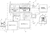
図1には、ドリル、フライス(ミルカッタ)、それらに類似するものといった機械加工用の工具を生産するための研削盤1が示されている。工具を加工・製造するために使用する機械加工用工具と区別するため、ここでは生産される工具は「工作物」と呼ぶこととする。
FIG. 1 shows a grinding
研削盤1は、固定式もしくは可変形式で維持されている工作物支持装置(支持台)2を備える。工作物支持装置(支持台)2は工作物9(未加工のもの、加工中のもの、完成したもの)を支持(例えば、チャッキング)する。
研削盤1自体も、固定して設置することも可能であるし、三次元空間中の任意の方向へ位置調節装置によって移動・調節することも可能である。
工作物支持装置2に対応して、一つもしくは複数の研削砥石(研削ホイール)を備える研削ヘッド3が配置されている。研削ヘッド3は、空間内の多様な方向に移動及び旋回運動可能である。研削砥石4は回転駆動させられる。
The grinding
The grinding
A grinding
機械制御プログラム5は、研削ヘッド3と工作物支持装置2の両方もしくはいずれか一方の動作を制御し、相対的な運動を行わせる。なお、この機械制御プログラム5は、後述するプログラムジェネレータ6によって作成される。
機械制御プログラム5は、測定装置用の測定プログラム7をセットアップする。例えば、機械制御プログラム5は、研削盤1によって加工・製造された工作物9を測定する測定装置8用の測定プログラム7をセットアップする。
The
The
測定装置8は、工作物保持装置11と、一つあるいは複数の測定ヘッド12を備えている。測定ヘッド12は、工作物9上の測定ポイントを走査(スキャン)して、測定値を出力するように、位置決装置13(ポジショニングデバイス)によって空間的に移動可能に構成されている。
The measuring device 8 includes a
測定装置8は、図示したように、研削装置1から独立して構成させることも可能であるし、また、研削装置1の構成要素の一つとして構成させることも可能である。
The measuring device 8 can be configured independently of the grinding
プログラムジェネレータ6は、入力モジュール14を備えている。入力モジュール14は、機械制御プログラム5のセットアップと測定プログラム7のセットアップとに必要な全ての入力を取得するために用いられる。
入力は、個々の加工処理と関連し得る入力オブジェクト15を用いて、オブジェクト指向型でなされる。この点については、図6を参照して説明する。
The program generator 6 has an
The input is made in an object-oriented manner using an
図6は、ディスプレイ画面16の例を表している。ディスプレイ画面16は、例えばプログラムジェネレータ6が動作している研削盤1に備え付けられているPC(パーソナルコンピュータ)又は他のコンピュータ上の画面である。
ディスプレイ画面16は、その第1の入力領域17に、ユーザにより操作(選択)可能な個々の入力オブジェクトを備える。
FIG. 6 shows an example of the
The
図6は、例として入力オブジェクト「Clearance Step 2,Line(クリアランスステップ2ライン)」がアクティブ(有効・選択)になっているときの図であり、入力オブジェクト「Clearance Step 2,Line」の背景を明るく表示し、活性化されていることが視覚的に判断可能である。
FIG. 6 is a diagram when the input object “
各入力オブジェクトは、以下の意味を有している。
「Probing, End Of Tool(プロービング,工作物の終端)」:ゼロ(基準点)点を検出するために、ブランクの終端面を探知する。
Each input object has the following meaning.
"Probing, End Of Tool": Detects the end face of the blank to detect the zero (reference point) point.
「Fluting(フルーティング)」:溝を作成する。この入力オブジェクトは、「Clearance Step1, Od(クリアランスステップ1,Od)」から「Clearance StepEf(クリアランスステップEf)」へと展開する、より詳細な項目を含む。
「Operation(オペレーション)」と見出しされた領域では、図示されていない他の任意の入力オブジェクト(処理)を選択することも可能である。
"Fluting": Create a groove. This input object includes more detailed items that expand from “
In the area headed “Operation”, any other input object (processing) not shown can be selected.
様々な工具(ここでは、研削ホイール)を、各入力オブジェクトに対応付けることが可能である。これらは、「Wheel(ホイール)」という見出しの入力領域で選択可能である。図6では、例として、1V1, 11Vg,12Vg等のタイプの研削ホイールを選択可能である。 Various tools (here, grinding wheels) can be associated with each input object. These can be selected in the input area under the heading "Wheel". In FIG. 6, a grinding wheel of a type such as 1V1, 11Vg, 12Vg can be selected as an example.
図6は、入力オブジェクトと工具の選択が既になされており、選択されたラインに表示され、背景が明るくなっている状態を示している。 FIG. 6 shows a state in which the input object and the tool have already been selected, are displayed on the selected line, and have a bright background.
各入力オブジェクトには、入力パラメータが関連付けられている。
例えば、図6で選択状態にある入力オブジェクト「Fluting(フルーティング)」に関連付けられているものは、「クリアランスステップ2,ライン」と見出しされた入力領域18で最初にアクセス可能な入力パラメータである。ここで、入力領域18は、入力オブジェクトをパラメータ化するために利用される。各種寸法、比率、その他の入力パラメータが、入力領域18から入力可能である。
Each input object is associated with an input parameter.
For example, what is associated with the selected input object "Fluting" in FIG. 6 is the first accessible input parameter in the
図1で、入力パラメータ供給部19は、入力オブジェクト15内の個々の入力オブジェクトに関係付けられていることを意味する。
In FIG. 1, the input
入力モジュール14からは、他の情報を入力することも可能である。
この目的は、リンク22と、選択された入力オブジェクトと、入力オブジェクトのためのパラメータと関連する測定オブジェクト供給部21によって、実現される。この点を図7を参照して説明する。
Other information can also be input from the
This purpose is achieved by the
測定オブジェクトは、測定パラメータ、検査ポイント(測定ポイント)、角度、それらと類似するもののいずれでも良い。
図7においては、測定パラメータは、測定オブジェクト(見出し名「Primary Clearance Width(第1クリアランス幅)」)として選択されている。測定オブジェクトを予め保管しているメニュー23(見出し名「Measurement(測定)」)を開くことによって、測定オブジェクトとして特定の入力オブジェクトの入力パラメータを選択する作業は実行される。
The measurement object may be any of measurement parameters, inspection points (measurement points), angles, and the like.
In FIG. 7, the measurement parameter is selected as a measurement object (heading name “Primary Clearance Width (first clearance width)”). The operation of selecting an input parameter of a specific input object as a measurement object is executed by opening a menu 23 (heading name “Measurement (measurement))” storing measurement objects in advance.
メニュー23は、メニュー選択領域24上に配列されている。メニュー選択領域24内には、様々な工作物のプロフィール、研削砥石、研削盤と工作物の断面が、それぞれの場合で供給(supply)として、副次的なメニュー内に用意され、保管されている。
測定パラメータとしての「Primary Clearance Width(第1クリアランス幅)」)の定義は、入力領域内の色づけされた背景と、その隣にある大文字Mによる入力パラメータの指示とのいずれか一方、もしくは両方によって、図7に示されている。
The
The definition of “Primary Clearance Width” as a measurement parameter is defined by either or both of the colored background in the input area and the input parameter designation by capital letter M next to it. , Shown in FIG.
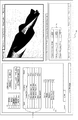
図8は、測定オブジェクトである、検査ポイントを入力するための画面を示している。 検査ポイントを入力する場合には、測定メニュー23を開く。
ディスプレイ画面16の表示領域において、入力オブジェクトと入力パラメータによって構成される工作物が視覚的に表示される。
表示された工作物の任意の位置AとBとをマウスでクリックすることで、検査ポイントAとBとがセットされ、検査ポイントAとBの座標と半径とに基づいて、測定メニューに反映される。
FIG. 8 shows a screen for inputting an inspection point, which is a measurement object. When inputting an inspection point, the
In the display area of the
By clicking the displayed arbitrary positions A and B of the workpiece with the mouse, the inspection points A and B are set and reflected on the measurement menu based on the coordinates and the radius of the inspection points A and B. You.
「Measurement Function(測定機能)」メニューを開いて、このメニュー上で指定することにより、検査ポイントの機能が定められる。本実施例では、間隔と角度が選択されている。
一旦、検査ポイントがボディの端に置かれると、プログラムは、検査ポイントが端に設定されていると判断する。こうして検査ポイントは、入力オブジェクトに関連付けられ、彼ら自身によって、または共同して適用可能な端を定める。例えば、検査ポイントAについては、これらは、隣接するつかみ(チャッキング)のためのスペースと隣接するフランクのための入力オブジェクトである。
The function of the inspection point is determined by opening the "Measurement Function" menu and specifying the menu. In this embodiment, the interval and the angle are selected.
Once the test point is located at the edge of the body, the program determines that the test point is set at the edge. The inspection points are thus associated with the input objects and define the applicable end by themselves or jointly. For example, for inspection point A, these are the input objects for adjacent chucking and adjacent flanks.
プログラムジェネレータ6は、機械加工プログラムモジュール25を含む。このモジュール25は、入力モジュールによって得られたデータを、機械制御プログラムに変換する。これは、パラメータ化された入力オブジェクトを、選択された研削盤の幾何学的形状に基づいたNCデータへ変換することによってなされる。入力オブジェクトは、それぞれが、既に工作物と研削盤間の相対動作を定めている。
The program generator 6 includes a
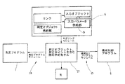
プログラムジェネレータ6は、モデリングモジュールを含んでいる。モデリングモジュールは、ディスプレイモジュール26の一部として構成されることも可能であるし、ディスプレイモジュール26等に接続されることも可能である。ディスプレイモジュール26は、ディスプレイ画面16の表示領域と協働する。モデリングモジュールは、生成される工作物を表示するための幾何学的モデル27を作成する。幾何学的モデル27は、作業結果(例えば、完全に加工された工作物)の数学的な表現と同様に、研削盤1への全ての作業命令を含んでいる。
The program generator 6 includes a modeling module. The modeling module can be configured as a part of the
上述の構成に代えて、ディスプレイモジュール26は、モデリングモジュールに接続されずに、幾何学的モデル27に接続されることも可能である。幾何学的モデル27は、測定プログラム7をセットアップするための基準を作成する。これは、幾何学モデルから得られたデータと、測定作業に関するデータとを組み合わせる測定プログラムモジュール28によって提供される。
Instead of the above configuration, the
測定作業に関するデータは、決定された測定オブジェクト供給部21と関連するリンク22とに基づいて、入力モジュール14から、測定プログラムモジュールによって受け取られる。
Data relating to the measurement task is received by the measurement program module from the
仮に、例えば、検査ポイントA、B間のフランク(逃げ面)が、幾何学的モデル内に定められた形式で存在し、そして、測定オブジェクト、換言すれば測定ポイントA、Bとそれらの評価が半径や角度を定める形式で既定されている場合、測定プログラムは、位置決装置13の位置に関する必要な動作と、結果として得られるデータの評価を予め決定することが可能である。 If, for example, the flank (flank) between the inspection points A and B exists in a defined form in the geometric model, and the measurement objects, in other words the measurement points A and B and their evaluation, If the radius and the angle are defined in a predetermined format, the measurement program can determine in advance the necessary operation regarding the position of the positioning device 13 and the evaluation of the resulting data.
図2は、プログラムジェネレータ6の修正された実施例を示す。
プログラムの構造は、幾何学的モデル27内に存在するデータに基づいて、機械加工プログラムモジュール25が動作できるように修正されている。ディスプレイ画面16も、同様に幾何学的モデルのデータに基づいている。
測定プログラムモジュール28は、しかしながら、これまで通り、測定プログラム7をセットアップするために、入力モジュール14から得られたデータと、幾何学的モデル27から得られたデータとを組み合わせている。
FIG. 2 shows a modified embodiment of the program generator 6.
The structure of the program has been modified so that the
The
図3は幾何学的モデル27の機能を集中化させた実施例を示している。ここで、幾何学的モデル27は、作成する工作物の3次元の位置に関する情報だけでなく、実行される加工作業に関する情報と、実施される測定作業に関する情報とを含んでいる。
これらのデータは、入力モジュール14から得られる。
FIG. 3 shows an embodiment in which the functions of the
These data are obtained from the
機械加工プログラムモジュール25と測定プログラムモジュール28とは、共に、幾何学的モデル27に基づき作業を実行する。
The
測定オブジェクトの入力パラメータにおける、または、入力オブジェクトもしくはパラメータと関連する測定オブジェクトのリンクにおける、あらゆる変化が、幾何学モデルに影響を与える。変化は、幾何学モデルだけでなく機械制御プログラム5と測定プログラム7との両方に影響を与える。加えて、ディスプレイ画面16上の表示も、その変化に適合させられる。
Any change in the input parameters of the measurement object or in the link of the measurement object associated with the input object or parameter will affect the geometric model. The change affects both the
図6乃至図8に示されたディスプレイ画面16にとって、これは、例えば、ディスプレイ画面16を用いて検査ポイントA、Bが配置された後に、そのポイントが幾何学的モデルに入力されることを意味する。
仮に、ユーザが、図1に示されるメニュー内の入力パラメータの数値、例えば「第一クリアランス幅」を1ミリメートルから2ミリメートルに変更したとすると、修正された加工作業が実行可能な範囲内に存する場合、適切な表示画面(工作物の画像)が表示される。
図8の明るい部分は、修正に相当する様に広くなる。また、検査ポイントA、Bは、変更された後の相当する端に再度位置設定され、いままでよりお互いに遠くなる。図8で示したメニューで、例えば「測定間隔(Measurement Distance)」領域に表示されている数値も変化する。
For the
If the user changes the numerical value of the input parameter in the menu shown in FIG. 1, for example, the “first clearance width” from 1 mm to 2 mm, the corrected machining operation is within the executable range. In such a case, an appropriate display screen (image of the workpiece) is displayed.
The bright part in FIG. 8 becomes wider to correspond to the correction. Further, the inspection points A and B are repositioned at the corresponding ends after being changed, and are farther from each other than before. In the menu shown in FIG. 8, for example, the numerical value displayed in the “Measurement Distance” area also changes.
なお、この点に関して、パラメータ化された入力オブジェクトは、機械加工作業を示し、又は記述する。機械加工作業は重ねて実行されるため、入力オブジェクトのパラメータだけが、間接的に工作物の幾何学的形状を定めている。
これは、検査ポイントA、Bが固定され、図6乃至8で明るい色で示されているフランクを考察すれば、明らかとなる。
このフランクを特徴付ける入力オブジェクトは、研削砥石が導かれる三次元方向の距離を定めている。しかしながら、このフランクの切刃(cutting edge)の端(境界)は、見出し名が「つかみ(チャッキング)スペース」の入力オブジェクトによって定まる。なぜなら、そのパラメータは、材料が切刃(cutting edge)の部分で、どのくらい除去されるか、換言すれば、物質が正確にどの位置にあるかを示しているからである。検査ポイントAとB間の距離で定まるフランクの広さは、純粋に入力された数値だけで定まるのではなく、機械加工によって定まる。
Note that in this regard, the parameterized input object indicates or describes the machining operation. Since the machining operations are performed in tandem, only the parameters of the input object indirectly determine the geometry of the workpiece.
This becomes apparent when examining the flank where inspection points A and B are fixed and are shown in bright colors in FIGS.
The input object characterizing this flank defines the distance in three dimensions in which the grinding wheel is guided. However, the end (boundary) of this flank cutting edge is determined by the input object whose heading name is "grabbing (chucking) space". Because the parameters indicate how much material is removed at the cutting edge, in other words, exactly where the substance is located. The width of the flank determined by the distance between the inspection points A and B is determined not only by purely input numerical values but also by machining.
一般的な幾何学的モデル27に基づく、機械加工プログラムモジュール25と測定プログラム28間の相互作用は、相互作用の効果や、スクリーン上の個々の機械加工作業の相互作用を視覚化するだけでなく、関連する測定プログラムを作成することができる。
The interaction between the
図5と図6は、異なる観点に立ち、再度機械制御プログラム5と測定プログラム7との作成手順を示している。
5 and 6 show the procedure for creating the
適切なメニュー入力によって、作成される工作物(工具)の種類が、第一に選択される。
これは、例えば、図6乃至図8の「プロフィール(Profiles)」メニューで行われる。これには、例えば、歯を備える工作物の場合には、歯の数を定めるようなことも含まれる。歯の数に従って、各歯の情報を入力するための、入力領域18を備えるファイルカードが生成される。図6〜図8の例では、工作物が4枚の歯を有しており、各歯に1つ、計4枚のファイルカードが生成される。これは、図4の左上に円形で示されているイベントにも適用される。この円形フィールドに従って、例えばチップスペース(溝)や新たな動作が入力される。即ち、イベント毎に入力用のファイルカードが生成される。
By appropriate menu entry, the type of workpiece to be created (tool) is first selected.
This is done, for example, in the "Profiles" menu of FIGS. This includes, for example, determining the number of teeth in the case of a workpiece having teeth. According to the number of teeth, a file card having an
次に、適用可能な入力オブジェクトがパラメータ化される。当初は、基準値(初期設定値)を用いて行われる。そして、基準値によるパラメータ化は、次の場面で、視覚的に明らかとなり、ユーザによって調整・修正される。 Next, the applicable input objects are parameterized. Initially, this is performed using a reference value (initial setting value). The parameterization based on the reference value is visually evident in the next scene, and is adjusted and corrected by the user.
次のステップで、選択され、パラメータ化された入力オブジェクトの動作中、測定プログラムモジュール(図1、図2、又は図3)は、研削砥石が空間に残す軌道を作成する。研削砥石の軌道はメモリに保管される。次の中心となるステップでは、その軌道はブランク(もしくは、一部加工された工作物)から減算され(その軌道上の部分がブランクから除去され)その結果、最も新しく入力作業が実行された工作物の幾何学的モデルが生成される。 In the next step, during the operation of the selected and parameterized input object, the measurement program module (FIG. 1, FIG. 2, or FIG. 3) creates a trajectory that the grinding wheel leaves in space. The trajectory of the grinding wheel is stored in a memory. In the next central step, the trajectory is subtracted from the blank (or the partially machined workpiece) (the part on the trajectory is removed from the blank), resulting in the most recently executed workpiece. A geometric model of the object is generated.
ほぼ全ての入力作業が実行されるまで(換言すれば、入力オブジェクトに基づき実行される全ての物質的な減算によって、工作物の幾何学的モデルが作成されるまで)この処理は、必要なだけ何回でも繰り返される。 This process is only necessary until almost all the input work has been performed (in other words, until a geometric model of the workpiece has been created by all material subtractions performed on the input object). It is repeated as many times.
工作物の幾何学的モデルが生成され、検査と確認作業が済むと、このモデルからNCプログラムを作成する。作成されたNCプログラムは、研削盤に送信され、研削盤で実行される。 Once a geometric model of the workpiece has been generated and inspected and verified, an NC program is created from this model. The created NC program is transmitted to the grinding machine and executed on the grinding machine.
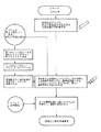
図5は測定プログラムのセットアップにおける、イベント指向型のデータフロー図を示している。 FIG. 5 shows an event-oriented data flow diagram in setting up a measurement program.
始点は、完成した工作物(機械工具)の幾何学的モデルである。
画面上での工作機械のセットアップの際、ユーザが、測定または検査ポイントを未だ設定していないことも想定されている。
ユーザが設定を希望する場合、ユーザが測定パラメータを選択した際に「追加測定パラメータ」と名付けられたイベントが表れる。
The starting point is a geometric model of the completed workpiece (machine tool).
When setting up the machine tool on the screen, it is also assumed that the user has not yet set the measurement or inspection points.
If the user wishes to make settings, an event named "Additional Measurement Parameter" appears when the user selects a measurement parameter.
測定パラメータに関するこれらの情報(追加の測定パラメータ)は、幾何学的モデルに追加される。幾何学的モデルに様々な測定パラメータを追加するために、この作業は、ほぼ任意に必要に応じて繰り返される。 These information on the measurement parameters (additional measurement parameters) are added to the geometric model. This operation is almost arbitrarily repeated as needed to add various measurement parameters to the geometric model.
測定内容について予め規定しておく可能性のある事項としては、例えば、検査ポイントとその意義を記入することである。これは、図5の左中央のステップに示されている。入力は、図8のマスクによってなされる。得られた情報は、幾何学的モデルに追加される。 An example of a possibility of preliminarily defining the measurement content is to enter an inspection point and its significance. This is shown in the middle left step of FIG. The input is made by the mask of FIG. The obtained information is added to the geometric model.
すべての測定パラメータと検査ポイントが揃って、幾何学的モデルが完成すると、測定プログラムは、3次元幾何学的モデルから作成され、測定機械に送信される。 When all the measurement parameters and inspection points are completed and the geometric model is completed, a measurement program is created from the three-dimensional geometric model and transmitted to the measuring machine.
1 研削盤
2 工作物支持装置(支持台)
3 研削ヘッド
4 研削砥石
5 機械制御プログラム
6 プログラムジェネレータ
7 測定プログラム
8 測定装置
9 工作物
11 工作物保持装置
12 測定ヘッド
13 位置決装置
14 入力モジュール
15 入力オブジェクト
16 ディスプレイ画面
17 第1の入力領域
18 入力領域
19 入力パラメータ供給部
21 測定オブジェクト供給部
22 リンク
23 メニュー
24 メニュー選択領域
25 機械加工プログラムモジュール
26 ディスプレイモジュール
27 幾何学的モデル
28 測定プログラムモジュール
1 grinding
3 grinding
Claims (15)
選択された入力オブジェクトおよび入力を基に、工作物(9)の像を視覚的に表示するためのディスプレイモジュール(26)と、
入力オブジェクトの選択および入力されるパラメータから、工作機械(1)を制御するための機械制御プログラム(5)を作成する機械加工プログラムモジュール(25)と、
測定オブジェクトの選択とそれらの入力オブジェクトとのリンクから、測定装置(7)を制御する測定プログラムとして機能する測定プログラムモジュール(28)と、
を備えることを特徴とする工具製造のための統合装置。 Provide an accessible input object (15) for depicting the workpiece (9)-each input object has an input parameter (19) belonging to that input object-- An input module (14) for enabling selection and input of input parameters (15) and for providing an accessible measurement object which is selectable and linked to the input object or the input parameter;
A display module (26) for visually displaying an image of the workpiece (9) based on the selected input object and the input;
A machining program module (25) for creating a machine control program (5) for controlling the machine tool (1) from selection of input objects and input parameters;
A measurement program module (28) functioning as a measurement program for controlling the measurement device (7) from the selection of the measurement objects and the link with those input objects;
An integrated device for manufacturing a tool, comprising:
入力モジュールにより、
a) 加工物の描写のセットアップのために動作し、選択のために提供され、それぞれに一又は複数の入力パラメータが帰属する入力オブジェクトを提供し、
b) 選択対象として測定オブジェクトを提供し、
測定オブジェクトの選択により、入力オブジェクトとのリンクを引き出し、
ディスプレイモジュールにより、選択した入力オブジェクトと入力から得られた工具のイメージを表示し、
機械加工プログラムモジュール(25)を用いて、選択された入力オブジェクトと入力パラメータとに基づき、工作機械(1)を制御する機械制御プログラムを生成し、
測定プログラムモジュールを用いて、測定オブジェクトの選択と、該選択された測定オブジェクトと入力オブジェクトとの関係とから、測定装置を制御する測定プログラムを作成する、
ことを特徴とする工作機械と関連する測定装置を制御する方法。 A method for controlling a measuring device associated with a machine tool, the method comprising:
a) providing an input object that operates for the setup of the depiction of the workpiece and is provided for selection, each belonging to one or more input parameters;
b) providing a measurement object for selection;
By selecting the measurement object, pull out the link with the input object,
The display module displays the selected input object and the image of the tool obtained from the input,
Using the machining program module (25), generate a machine control program for controlling the machine tool (1) based on the selected input object and input parameters,
Using the measurement program module, from the selection of the measurement object and the relationship between the selected measurement object and the input object, create a measurement program that controls the measurement device,
A method for controlling a measuring device associated with a machine tool.
Applications Claiming Priority (1)
| Application Number | Priority Date | Filing Date | Title |
|---|---|---|---|
| DE10261227A DE10261227A1 (en) | 2002-12-20 | 2002-12-20 | Integrated tool manufacturing facility and process |
Publications (1)
| Publication Number | Publication Date |
|---|---|
| JP2004206723A true JP2004206723A (en) | 2004-07-22 |
Family
ID=32336616
Family Applications (1)
| Application Number | Title | Priority Date | Filing Date |
|---|---|---|---|
| JP2003425705A Pending JP2004206723A (en) | 2002-12-20 | 2003-12-22 | Tool manufacturing device and manufacturing method |
Country Status (10)
| Country | Link |
|---|---|
| US (1) | US7050925B2 (en) |
| EP (1) | EP1431851B1 (en) |
| JP (1) | JP2004206723A (en) |
| KR (1) | KR100624358B1 (en) |
| CN (1) | CN100442179C (en) |
| AT (1) | ATE440314T1 (en) |
| BR (1) | BR0306048A (en) |
| DE (2) | DE10261227A1 (en) |
| ES (1) | ES2330734T3 (en) |
| TW (1) | TWI336428B (en) |
Cited By (1)
| Publication number | Priority date | Publication date | Assignee | Title |
|---|---|---|---|---|
| CN102540975A (en) * | 2010-12-14 | 2012-07-04 | 厦门特盈自动化科技股份有限公司 | Turning and cutting control method of trivariant screw |
Families Citing this family (11)
| Publication number | Priority date | Publication date | Assignee | Title |
|---|---|---|---|---|
| CN100351805C (en) * | 2002-12-26 | 2007-11-28 | 三菱电机株式会社 | Manipulation program producing appts. |
| JP2006172344A (en) * | 2004-12-20 | 2006-06-29 | Sumitomo Rubber Ind Ltd | Method for designing product shape |
| DE102008055665A1 (en) * | 2008-11-03 | 2010-05-06 | E. Zoller GmbH & Co. KG Einstell- und Messgeräte | Tool measuring device for use in computer numerical control milling machine, has computing unit generating information of data set obtained by determination of tool, where computing unit performs rehabilitation process for tool |
| TWI500475B (en) * | 2012-12-13 | 2015-09-21 | Ind Tech Res Inst | Apparatus and method for positioning geometric model |
| DE102013015239A1 (en) * | 2013-09-13 | 2015-03-19 | Liebherr-Verzahntechnik Gmbh | Process for setting up a gear cutting machine and gear cutting machine |
| DE102014214365A1 (en) * | 2014-07-23 | 2015-07-16 | Carl Zeiss Industrielle Messtechnik Gmbh | Method for finding faulty measuring sequences in a coordinate measuring machine and apparatus for carrying out this method |
| WO2016189657A1 (en) * | 2015-05-26 | 2016-12-01 | 三菱電機株式会社 | Numerical control device and display control method |
| CN107825229A (en) * | 2017-11-14 | 2018-03-23 | 常州大思世成机电科技有限公司 | A kind of cast(ing) surface dressing method |
| JP7377088B2 (en) * | 2019-12-10 | 2023-11-09 | キヤノン株式会社 | Electronic devices and their control methods, programs, and storage media |
| CN111736528A (en) * | 2020-07-07 | 2020-10-02 | 华中科技大学 | Laser cutting automatic programming system based on vision deviation rectification |
| CN117102977B (en) * | 2023-09-11 | 2024-02-02 | 江苏中科云控智能工业装备有限公司 | Machine deburring track management system and method based on visual information |
Family Cites Families (14)
| Publication number | Priority date | Publication date | Assignee | Title |
|---|---|---|---|---|
| JPH02277102A (en) * | 1989-04-18 | 1990-11-13 | Toshiba Mach Co Ltd | Working program teaching system for numerically controlled machine tool |
| JPH03176703A (en) * | 1989-12-05 | 1991-07-31 | Yoshiaki Kakino | Numerical controller |
| GB2300052B (en) * | 1995-04-19 | 1998-04-29 | Honda Motor Co Ltd | Method of generating die structure data |
| JP3702496B2 (en) * | 1995-07-10 | 2005-10-05 | 三菱電機株式会社 | Machining method using numerical controller |
| DE19525542A1 (en) * | 1995-07-13 | 1997-01-16 | Mann & Hummel Filter | Heating device |
| DE19625542A1 (en) * | 1996-06-26 | 1998-01-02 | Zoller Gmbh & Co Kg E | Automatic CNC controlled measuring and checking machine for cutting tools |
| IT1293645B1 (en) * | 1997-07-25 | 1999-03-08 | Tacchella Macchine Spa | CONTROL DEVICE FOR GRINDING MACHINE |
| US5984503A (en) * | 1997-08-15 | 1999-11-16 | Vickers, Incorporated | Method and apparatus for entering and displaying structure information in a machining system |
| JP3071758B2 (en) * | 1998-05-20 | 2000-07-31 | ヤマザキマザック株式会社 | Three-dimensional laser beam machine and processing control method for processing program in three-dimensional laser beam machine |
| DE19900117A1 (en) * | 1999-01-05 | 2000-07-06 | Walter Ag | Virtual teach-in system |
| WO2001002914A1 (en) * | 1999-07-05 | 2001-01-11 | Mitutoyo Corporation | Method for writing nc program and nc machining system |
| DE10108688B4 (en) * | 2001-02-23 | 2013-01-31 | Carl Zeiss Industrielle Messtechnik Gmbh | measuring device |
| US6779175B2 (en) * | 2001-05-22 | 2004-08-17 | Thermwood Corporation | Method and system for converting graphic databases into coded workpiece processing programs |
| SI21200A (en) * | 2002-03-27 | 2003-10-31 | Jože Balič | The CNC control unit for controlling processing centres with learning ability |
-
2002
- 2002-12-20 DE DE10261227A patent/DE10261227A1/en not_active Withdrawn
-
2003
- 2003-11-25 DE DE50311826T patent/DE50311826D1/en not_active Expired - Lifetime
- 2003-11-25 AT AT03027063T patent/ATE440314T1/en active
- 2003-11-25 ES ES03027063T patent/ES2330734T3/en not_active Expired - Lifetime
- 2003-11-25 EP EP03027063A patent/EP1431851B1/en not_active Expired - Lifetime
- 2003-12-17 BR BR0306048-9A patent/BR0306048A/en not_active Application Discontinuation
- 2003-12-19 KR KR1020030094129A patent/KR100624358B1/en active IP Right Grant
- 2003-12-19 CN CNB2003101231359A patent/CN100442179C/en not_active Expired - Lifetime
- 2003-12-19 TW TW092136066A patent/TWI336428B/en not_active IP Right Cessation
- 2003-12-19 US US10/739,147 patent/US7050925B2/en not_active Expired - Lifetime
- 2003-12-22 JP JP2003425705A patent/JP2004206723A/en active Pending
Cited By (1)
| Publication number | Priority date | Publication date | Assignee | Title |
|---|---|---|---|---|
| CN102540975A (en) * | 2010-12-14 | 2012-07-04 | 厦门特盈自动化科技股份有限公司 | Turning and cutting control method of trivariant screw |
Also Published As
| Publication number | Publication date |
|---|---|
| DE50311826D1 (en) | 2009-10-01 |
| US7050925B2 (en) | 2006-05-23 |
| BR0306048A (en) | 2005-02-09 |
| ES2330734T3 (en) | 2009-12-15 |
| CN1527167A (en) | 2004-09-08 |
| EP1431851A1 (en) | 2004-06-23 |
| KR20040055703A (en) | 2004-06-26 |
| ATE440314T1 (en) | 2009-09-15 |
| DE10261227A1 (en) | 2004-07-22 |
| KR100624358B1 (en) | 2006-09-19 |
| TWI336428B (en) | 2011-01-21 |
| TW200416507A (en) | 2004-09-01 |
| EP1431851B1 (en) | 2009-08-19 |
| CN100442179C (en) | 2008-12-10 |
| US20050038624A1 (en) | 2005-02-17 |
Similar Documents
| Publication | Publication Date | Title |
|---|---|---|
| US8988032B2 (en) | Numerical controller having display function for trajectory of tool | |
| US6400998B1 (en) | Generation of measurement program in NC machining and machining management based on the measurement program | |
| JP6335925B2 (en) | Machine tool controller | |
| US6671571B1 (en) | Method for NC- programming and system for NC- machining | |
| US7761183B2 (en) | Methods and systems for producing numerical control program files for controlling machine tools | |
| US8588955B2 (en) | Method and apparatus for optimizing, monitoring, or analyzing a process | |
| JP6150903B2 (en) | Machining information management device and tool path generation device | |
| JP6719790B1 (en) | Automatic operation device for machining center based on CAD data | |
| JP2004206723A (en) | Tool manufacturing device and manufacturing method | |
| CN104460519B (en) | Control the method and gear cutting machine of gear cutting machine | |
| JP4180469B2 (en) | How to check the machining suitability of machine tools | |
| CN116057483A (en) | Manufacturing a surface determinable by a cone section using a machine tool | |
| US20040210868A1 (en) | Icons and icon representation of process steps for graphic visualization of task-oriented steps | |
| KR20100135513A (en) | Numerical control system having graphic-based user interface | |
| KR20170124768A (en) | Tool path correction method of machining tools | |
| US20220107626A1 (en) | Method and apparatus for cycle-based programming of a control program for a numerically controlled machine tool | |
| Sultana et al. | SolidCAM iMachining (2D): a simulation study of a spur gear machining and G-code generation for CNC machine | |
| WO2024069951A1 (en) | Machine tool control device and machine tool display device | |
| JPH03156506A (en) | Nc program generating method for interactive numerical controller or automatic programming device | |
| Westlin | Integrated System for Machining Process Visualization and Analysis in Blade Applications | |
| Suh et al. | Man–Machine Interface | |
| JPH11104935A (en) | Method for automatically preparing program for nc machine tool |
Legal Events
| Date | Code | Title | Description |
|---|---|---|---|
| A711 | Notification of change in applicant |
Free format text: JAPANESE INTERMEDIATE CODE: A711 Effective date: 20060113 |
|
| A521 | Request for written amendment filed |
Free format text: JAPANESE INTERMEDIATE CODE: A821 Effective date: 20060113 |
|
| A621 | Written request for application examination |
Free format text: JAPANESE INTERMEDIATE CODE: A621 Effective date: 20060911 |
|
| A621 | Written request for application examination |
Free format text: JAPANESE INTERMEDIATE CODE: A621 Effective date: 20061102 |
|
| RD02 | Notification of acceptance of power of attorney |
Free format text: JAPANESE INTERMEDIATE CODE: A7422 Effective date: 20061102 |
|
| A521 | Request for written amendment filed |
Free format text: JAPANESE INTERMEDIATE CODE: A821 Effective date: 20061122 |
|
| RD04 | Notification of resignation of power of attorney |
Free format text: JAPANESE INTERMEDIATE CODE: A7424 Effective date: 20061122 |
|
| A131 | Notification of reasons for refusal |
Free format text: JAPANESE INTERMEDIATE CODE: A131 Effective date: 20090303 |
|
| A02 | Decision of refusal |
Free format text: JAPANESE INTERMEDIATE CODE: A02 Effective date: 20090804 |